Geosynthetic Opportunities Associated With Shale ... - Geosynthetica
Geosynthetic Opportunities Associated With Shale ... - Geosynthetica
Geosynthetic Opportunities Associated With Shale ... - Geosynthetica
You also want an ePaper? Increase the reach of your titles
YUMPU automatically turns print PDFs into web optimized ePapers that Google loves.
<strong>Geosynthetic</strong> Institute<br />
475 Kedron Avenue<br />
Folsom, PA 19033-1208 USA<br />
TEL (610) 522-8440<br />
FAX (610) 522-8441<br />
GEI<br />
GRI<br />
GSI<br />
GAI GCI<br />
GII<br />
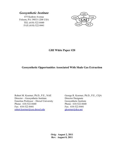
GRI White Paper #20<br />
<strong>Geosynthetic</strong> <strong>Opportunities</strong> <strong>Associated</strong> <strong>With</strong> <strong>Shale</strong> Gas Extraction<br />
Robert M. Koerner, Ph.D., P.E., NAE<br />
George R. Koerner, Ph.D., P.E., CQA<br />
Director – <strong>Geosynthetic</strong> Institute<br />
Director Designate<br />
Emeritus Professor – Drexel University <strong>Geosynthetic</strong> Institute<br />
Phone: 610-522-8440 Phone: 610-522-8440<br />
Fax: 610-522-8441 Fax: 610-522-8441<br />
robert.koerner@coe.drexel.edu<br />
gkoerner@dca.net<br />
Orig: August 2, 2011<br />
Rev: August 8, 2011
<strong>Geosynthetic</strong> <strong>Opportunities</strong> <strong>Associated</strong> <strong>With</strong> <strong>Shale</strong> Gas Extraction<br />
Abstract<br />
While natural gas contained within shale rock is geologic by its very nature, the practice<br />
of its removal by horizontal drilling coupled with hydrofracing is quite recent. Indeed, these<br />
dual technologies are making possible the recovery of huge amounts of natural gas. So much so<br />
that one can envision natural gas as an energy source rivaling oil, coal and nuclear, while<br />
dwarfing all of the renewables combined. The potential in this regard is awesome particularly<br />
since it is worldwide in its availability and opportunities.<br />
This white paper briefly describes shale gas drilling and extraction operations, along with<br />
its associated environmental concerns. Using this as a background, the paper then describes and<br />
illustrates many geosynthetic materials opportunities that exist in order to make the overall<br />
operations more efficient, economical, and environmentally acceptable.<br />
<strong>Shale</strong> Gas Plays *<br />
<strong>Shale</strong> is a fine-grained sedimentary rock which is formed by heat and pressure over<br />
geologic time. Many formations contain organic materials (they are then called oil shales),<br />
which upon decay, generates natural gas within the rock itself. The liberation, capture and<br />
transmission of this gas is at the heart of the technology. It should be mentioned that natural gas<br />
has traditionally accompanied oil drilling operations and has historically been a nuisance to oil<br />
drillers.<br />
However, this same gas now takes “center stage” insofar as this white paper is<br />
concerned.<br />
<strong>Shale</strong> gas plays are both nationwide and worldwide in their occurrence, e.g., see Figure 1<br />
in which the data is in units of trillions of cubic meters. In the U.S., there is activity in many<br />
states as Figure 2 indicates. Of the locations shown, the Barnett formation in the Fort Worth<br />
* The word “plays” is customarily used when describing the exploration, drilling, hydrofracturing and recovery of<br />
natural gas as described herein.<br />
-1-
asin is very significant since it was the first large-scale operation using these newer drilling and<br />
extraction technologies. By 2004, it had been explored by 15,000 deep wells, over 4000 in 2007<br />
alone, and had produced 1.4 trillion cubic feet; TCF (0.04 trillion cubic meters, TCM) of natural<br />
gas in 2008. It appears as though horizontal drilling at great depths coupled with hydraulic<br />
fracturing was perfected in the Barnett shale of Texas.<br />
Figure 1 – Worldwide conventional and shale gas reserves (The Economist, August 6, 2011).<br />
Figure 2 – United States shale gas plays (compl. Wikipedia).<br />
-2-
The most recent major gas play is in the Marcellus formation underlying major parts of<br />
Pennsylvania, New York, Ohio and West Virginia. Figure 3 shows the extent and depth of this<br />
formation, in which it is seen to be near surface in Ohio, but 7000 ft (2100 m) deep in<br />
Pennsylvania and New York. The Marcellus formation is about 800 ft. (40 m) thick in these two<br />
states and only 50 feet (15 m) thick in Ohio. Pennsylvania is currently in full production of<br />
natural gas with 2815 producing wells and 3300 permits granted in 2010 (up from 117 in 2007).<br />
Meanwhile, New York has a temporary moratorium on gas drilling pending legislative action<br />
expected in the near future.<br />
Figure 3 – Plan and elevation views of Marcellus <strong>Shale</strong> (compl. Wikipedia).<br />
-3-
The Marcellus formation is a 400 M year old marine sedimentary rock named for an<br />
outcrop near Marcellus, New York. The bedding is well developed and it is relatively easy to<br />
fracture. That said, at these depths it requires approximately 15,000 lb/sq. in. (103 MPa) to<br />
accomplish the fracturing. The in-situ and surface exposed features are apparent in Figure 4. Its<br />
organic content varies from 1 to 10% and it sometimes contains enough carbon to support<br />
combustion. The Marcellus is underlain by the Utica formation which is a much more extensive<br />
formation covering all of New York State and continues into Canada. To our knowledge the<br />
Utica formation is not being developed at this time nor are the overlying formations, the Upper<br />
Devonian shales. However, both of these formations are thought to have large potential gas<br />
plays.<br />
Figure 4 – In situ and fractured Marcellus shale (compl. Wikipedia).<br />
The U. S. Department of Energy estimates that the Marcellus contains 262 trillion cubic<br />
feet, or TCF (7.4 trillion cubic meters, or TCM) of natural gas. Conversely, Professor Terry<br />
Engelder of Penn State University estimates are much higher, i.e., 4,360 TCF (123 TCM) total of<br />
which 1,310 TCF (37 TCM) are recoverable. At a market price of $0.02/ft 3 ($0.71/m 3 ) the U.S.<br />
-4-
DOE estimated value is $5.2T, while Engelder’s is $26.2T. Whatever estimate holds true, the<br />
financial incentives are enormous. For example, Professor Timothy Considine of the University<br />
of Wyoming estimates that a typical Marcellus well generates $2.8 M in direct economic<br />
benefits, another $1.5 M from workers and landowners, and $2.0 M in federal, state and local<br />
taxes. This type of financial incentive is, of course, reflected in the present activity associated<br />
with shale gas extraction, transportation and eventual usage as an energy source.<br />
Regulations and Environmental Concerns<br />
The U.S. Energy Policy Act of 2005 was, and is, the foremost federal regulatory act<br />
governing shale gas plays of the type described in this white paper. Two aspects of this<br />
legislation have attracted considerable scrutiny;<br />
(i)<br />
(ii)<br />
hydrofracking was exempted from the Safe Drinking Water Act, and<br />
chemical additives to the water used for fracing were exempted from disclosure.<br />
To gain some perspective in this regard a chemical analysis of the flowback fracwater (at a<br />
specific site) is of interest, see Table 1. Note should be made of the highlighted alkaline<br />
minerals which results in an extremely brackish liquid about five-times the salinity of sea water.<br />
Also to be noted is the number of heavy metals, although the quantities are felt to be relatively<br />
low.<br />
Table 1 –Chemical Analysis of Flowback Water at a site near Williamsport, Pennsylvania<br />
(compl. CETCO)<br />
Na, mg/Kg 25,930 Mg, mg/Kg 725 Ag, mg/Kg 12<br />
K, mg/Kg 137 CL, mg/Kg 60,769 Au, mg/Kg 23<br />
Ca, mg/Kg 6,896 HCO 3 , mg/Kg 275 Ba, mg/Kg 5,145<br />
Fe, mg/Kg 39 Hg, mg/L
It should be noted that pending federal legislation, the so-called Frac Act of 2009, will require<br />
disclosure of fracing chemicals and place the entire process under U.S. Environmental Protection<br />
Agency regulations.<br />
At the state-level in Pennsylvania, shale gas operations are regulated under various<br />
departments, for example;<br />
<br />
<br />
<br />
drilling via the state Oil & Gas Division,<br />
fracing water via the state Field & Stream Division, and<br />
waste disposal via the state Solid Waste Division.<br />
In keeping with an emotionally-charged technology, such as natural gas plays, there are<br />
many environmental issues that have been raised by various concerned organizations, such as,<br />
federal, state and local regulatory groups, local water authorities, various industry groups,<br />
concerned citizens groups, etc. Some (but clearly not all) are mentioned below and have been<br />
selected because of the positive potential of using geosynthetic materials to solve, or at least<br />
mitigate, the issues listed:<br />
<br />
Containment and storage of large quantities of surface water for drilling and fracturing<br />
purposes.<br />
<br />
<br />
<br />
<br />
<br />
<br />
<br />
Storage and reuse of flow-back water from the hydrofracing process.<br />
Proper disposal of the “cuttings” from drilling operations (ca. 1000 tons per well).<br />
Drill pad site contamination (each being typically 3-5 acres in size).<br />
Frac-tank and storage area contamination.<br />
Access roads, parking and staging areas, and maintenance thereof.<br />
Minimizing site disturbance and providing level staging and working areas.<br />
Soil erosion and temporary containment so as to avoid stream and property<br />
contamination.<br />
-6-
In order to appreciate some of these environmental issues it is helpful to view a composite<br />
drilling operation as well as the enormity of the drilling wells themselves, see Figures 5a and 5b.<br />
Furthermore, some knowledge of the actual drilling operations are significant insofar as<br />
site development and maintenance. For example, a typical well site usually contains a number of<br />
vertical wells (3 to 6) which have horizontal branches going in different directions. Also, each<br />
well is generally hydraulically fractured several times. This iterative process depends upon the<br />
diminishing gas yield over time. Lastly, it is anticipated that a well pad should have a usable<br />
lifetime of approximately 20 to 30 years.<br />
Furthermore, the following generalized goals with these shale gas extraction plays are<br />
interesting to keep in mind as we now go into geosynthetic opportunities and solutions;<br />
<br />
the drilling operations are large construction projects with considerable public and<br />
regulatory scrutiny,<br />
<br />
<br />
<br />
once permitted, fast mobilization and deployment is necessary,<br />
a “low profile” is advantageous particularly with minimization of truck traffic, and<br />
benefit/cost is always important but maximum benefit often outweighs minimum cost.<br />
-7-
(a) Typical gas extraction operation in Marcellus <strong>Shale</strong> in Pennsylvania<br />
(b) Several large gas well drill rigs<br />
Figure 5 –Site operations at natural gas plays (compl. Wikipedia).<br />
-8-
<strong>Geosynthetic</strong> <strong>Opportunities</strong><br />
This section of the White Paper describes some of the many geosynthetic solutions that<br />
can be applied to shale gas plays. The section is subdivided according to (i) the drilling<br />
operations themselves, (ii) opportunities at permanent locations, and (iii) opportunities at<br />
temporary locations.<br />
<strong>Geosynthetic</strong>s <strong>Associated</strong> with Drilling Operations<br />
The first, and quite obvious, opportunity is the use of geomembranes for fresh water<br />
containment and subsequent use in the well drilling operations. The design stages are well<br />
known and consist of the following sequential steps:<br />
<br />
<br />
<br />
<br />
<br />
<br />
<br />
geometry (length, width, depth)<br />
cross section materials<br />
geomembrane type<br />
geomembrane thickness<br />
subgrade soil stability<br />
cover soil stability<br />
runout and anchor trench details<br />
Perhaps the most overlooked design detail is the requirement of providing an underdrain system<br />
beneath the geomembrane. Shown in Figure 6 are the all-to-common “whales” lifting up the<br />
geomembrane via rising gases within the underlying soil subgrade. Various underdrain solutions<br />
that should be considered are the following:<br />
<br />
<br />
<br />
<br />
<br />
thick needlepunched nonwoven geotextiles<br />
drainage geocomposites (complete or strips)<br />
interconnected perforated pipe system<br />
geotextiles with small perforated pipes<br />
sand bedding layer (with pipe network)<br />
-9-
Figure 6 – Some very recent whales (2009) in a potable water reservoir (compl. GSI).<br />
The second, and also obvious, opportunity is the containment and re-use of the flow back<br />
water which was characterized in Table 1 and is seen to be quite contaminated. Presently, this<br />
water is generally being held in mobile holding tanks (see Figure 7) but geomembrane lined<br />
ponds or even underground storage systems offer attractive alternatives. Figure 8 is a double<br />
lined contaminated surface impoundment in Virginia (the cross-section is soil subgrade,<br />
geotextile, geomembrane, geonet, geomembrane from bottom to top) and Figure 9 is an<br />
underground storage system that is typically used for storm water runoff from industrial and<br />
private development sites. Both strategies should be considered in contrast to hundreds of<br />
holding tanks interconnected to one another as shown in Figure 7.<br />
Figure 7 – Mobile holding tanks for frac-water (compl. Wikipedia).<br />
-10-
Figure 8 – Double-lined surface impoundment for contaminated water (compl. GSI).<br />
-11-
Figure 9 – Various underground storm water storage systems (compl. Rainstore®).<br />
-12-
A third opportunity for geosynthetics is the containment of cuttings from the drilling<br />
operation itself insofar as proper safe and secure disposal is concerned. In this regard, it should<br />
be mentioned that each well produces about 1000 tons (~ 75 truckloads) of contaminated cuttings<br />
of the type shown in Figure 10.<br />
cuttings<br />
Figure 10 – Contaminated cuttings from well drilling (compl. Wikipedia).<br />
These cuttings can, of course, go to a licensed public or private landfill but alternatively can be<br />
placed in geotextile tubes at the site (or within a landfill as seen in Figure 11) and can even have<br />
a decontaminant added such that the treated effluent can be released to the environment. The<br />
addition of charcoal, activated carbon, phosphoric rock, or organoclays is necessary and all are<br />
within decontamination technology that is associated with geotextile tubes.<br />
-13-
Figure 11 – Geotextile tubes located within a landfill as they are being filled whereby the<br />
effluent is automatically captured (compl. GSI).<br />
<strong>Opportunities</strong> at Permanent Locations<br />
Of first priority in this category are the roadways into and out of the drilling site which<br />
are necessary for the 20 to 30 years lifetime of the operations. Geotextiles and geogrids have<br />
been shown to save from 10 to 50% of the crushed stone thickness of base courses placed on soil<br />
subgrades * . The functions of separation, stabilization and/or replacement are clearly indicated in<br />
the literature since this application has been ongoing for about 30-years; see Figure 12. Not only<br />
is there a savings in stone base material, the distance from the quarry is significant in the total<br />
cost of the application.<br />
A second way of reducing crushed stone thickness there is considerable economy offered<br />
by using geocells as shown in Figure 13. They are filled with gravel, sand or locally available<br />
soil and their design (which uses a geotextile beneath them) is well established. Thicknesses<br />
saved are from 50 to 100% over the use of gravel by itself.<br />
* The old adage that “Ten pounds of soil and ten pounds of water make twenty pounds of mud” is seen at many drill<br />
sites particularly in the spring of the year.<br />
-14-
Figure 12 – Use of a geotextile (or geogrid) in an unpaved road applications<br />
(compl. IFAI/GMA).<br />
-15-
Figure 13 – Thick (~ 8.0 in or 200 mm) geocells (compl. PRS Med. Ltd.).<br />
Thirdly, these same geocells in a less-thick format are ideal for parking and staging areas<br />
located adjacent to the drill pad, see Figure 14.<br />
Fourth, locally available soils (even silts and clays) can be meaningfully strengthened by<br />
the addition of discrete fibers or microgrids, see Figure 15. Both types lead to major increases in<br />
shear strength in the upper 4 to 12 inches (100 to 300 mm) of surface. The technology is well<br />
advanced and mature at this point in time.<br />
-16-
Figure 14 – Less thick (~ 4 in or 100 mm) geocells (compl. CETCO Cont. Services).<br />
Figure 15 – Examples of discrete fibers and microgrids (compl. Propex and Tensar).<br />
Fifth, the drill pad site along with adjacent parking and staging areas must be level. To<br />
accomplish this in hilly terrain (as is typical in the Marcellus shale area) one needs to create<br />
stable soil slopes or even vertical walls. The concept of mechanically stabilized earth (MSE)<br />
slopes and walls using geogrid or geotxtile reinforcement is ideal in this regard. Not only are<br />
these situations the least expensive of all types of retaining structures (GRI Report #20), they are<br />
straightforward to construct, have no limitations as to curvature, height, or orientation, and have<br />
proven stable insofar as extreme surcharge loads are concerned; see Figure 16.<br />
-17-
Figure 16 – Vegetated MSE wall in Pennsylvania (compl. Waste Management, Inc.)<br />
-18-
Sixth, the drill pad itself should be lined so as to avoid contamination from spilled<br />
fracwater, hydrocarbons or other potential ground contaminates. This calls for a geomembrane,<br />
a geosynthetic clay liner, or both, as a composite liner. There are many choices in this regard<br />
and a designer should consider the generation of a benefit/cost ratio to select the appropriate liner<br />
material. See Table 2 for a hypothetical example situation. In it, the procedural steps are as<br />
follows:<br />
(a) select relevant site-specific properties as per application<br />
(b) weight properties from 10 (high) to 1 (low)<br />
(c) select candidate geomembrane types<br />
(d) grade types from 5 (high) and 1 (low)<br />
(e) multiply weight by grade<br />
(f) add resulting numbers<br />
(g) divide by estimated unit costs<br />
(h) select the geomembrane type with highest benefit/cost ratio<br />
Upon geomembrane selection, the engineer must now specify the properties. For the past<br />
several years there have been generic specifications available for common liner materials. Those<br />
that are currently available are the following:<br />
<br />
<br />
<br />
<br />
<br />
<br />
<br />
GRI-GM13 for high density polyethylene (HDPE)<br />
GRI-GM17 for linear low density polyethylene (LLDPE)<br />
GRI-GM18 for flexible polypropylene(fPP and fPP-R)<br />
GRI-GM21 for ethylene propylene diene terpolymer (EPDM and EPDM-R)<br />
GRI-GM25 for reinforced linear low density polyethylene (LLDPE-R)<br />
GRI-GCL3 for geosynthetic clay liners (GCL)<br />
ASTM-D7176 for polyvinyl chloride (PVC)<br />
-19-
Hypothetical Example Only<br />
Table 2 – Example B/C Matrix for Drill Pond Liner Geomembrane<br />
Property Weighting HDPE LLDPE fPP-R PVC CSPE-R EPDM-R<br />
chem. resist. 3 5 15 3 9 4 12 2 6 5 15 5 15<br />
durability 10 5 50 3 30 4 40 2 20 5 50 5 50<br />
UV stab. 8 5 40 3 24 4 32 2 16 5 40 5 40<br />
shear strength 7 4 28 4 28 3 21 3 21 3 21 3 21<br />
stress. crack 7 2 14 5 35 5 35 5 35 5 35 5 35<br />
seamability 9 4 36 3 27 3 27 4 36 3 27 2 18<br />
seam behavior 9 4 36 4 36 3 27 4 36 3 27 3 27<br />
strength 5 4 20 3 15 5 25 3 15 5 25 5 25<br />
elongation 5 4 20 5 25 2 10 5 25 2 10 2 10<br />
tear 6 3 18 2 12 5 30 2 12 5 30 5 30<br />
puncture 6 4 24 3 18 5 30 3 18 5 30 5 30<br />
impact 6 4 24 3 18 4 24 3 18 4 24 4 24<br />
exp./cont. 4 2 8 3 12 4 16 3 12 4 16 4 16<br />
constructability 10 3 30 4 40 4 40 5 50 4 40 4 40<br />
benefit n/a - 363 - 329 - 369 - 320 - 390 - 381<br />
cost/m 2 n/a - 10.00 - 10.50 - 11.25 - 9.00 - 12.50 - 13.00<br />
B/C ratio n/a - 36.3 - 31.3 - 32.8 - 35.5 - 31.2 - 29.3<br />
-20-
Seventh, natural gas plays are replete with plastic pipe. Such pipe as shown in Figure 17<br />
is used for many purposes such as;<br />
<br />
<br />
<br />
<br />
fresh water transmission<br />
frac water transmission<br />
gas transmission<br />
surface water drainage<br />
Figure 17 – HDPE solid wall, PVC solid wall, and HPDE corrugated pipe (various sources).<br />
-21-
The pipe is generally HDPE or PVC and can be solid wall (for transmission) or corrugated with<br />
slots or holes (for drainage). Whatever the case, natural gas plays require the use of plastic pipe<br />
in a major way.<br />
<strong>Opportunities</strong> at Temporary Locations<br />
First of all, temporary roadways of weeks or months are necessary in connection with<br />
setup and eventual demobilization at natural gas plays. The geosynthetics industry has the<br />
capability of providing wearing surfaces placed directly on the ground. Shown in Figure 18 are<br />
light and heavy roadway systems developed by the Dutch Military for rapid deployment of heavy<br />
vehicles and equipment. They are typically 60 ft. long and 10 ft. wide and the weight varies with<br />
type. Obviously, they can be redeployed as often as necessary.<br />
Secondly, temporary dams may be used for surface water control or for accidental spills<br />
associated with the drilling or containment operations. Figure 19 shows that geomembranes can<br />
readily provide such temporary containment and be adaptable to myriad applications.<br />
Third, on sloping surfaces soil erosion is a concern and must be avoided so as to prevent<br />
silting of off-site areas and local streams and rivers. Geotextile silt fences have played an<br />
economical role in this regard for decades. Figure 20 shows such a silt fence being installed and<br />
properly functioning.<br />
Fourth, rather than containing the site’s erosion after it occurs it is better to control and<br />
stabilize it before it starts. This has been traditionally provided by geosynthetic-erosion control<br />
materials of which there are a great variety. The two major categories are shown in Figure 21 for<br />
slopes and channels/ditches, respectively. Designs are well advanced in both cases.<br />
-22-
(a) Light trackway type<br />
(b) Heavy trackway type<br />
Figure 18- Temporary roadways developed by the Dutch military.<br />
-23-
Figure 19 – Temporary containment systems (compl. Portadam®).<br />
(a) Silt fence installation (compl. IFAI)<br />
(b) Properly perofrming silt fence (compl. GSI)<br />
Figure 20 – Silt fence for erosion control.<br />
-24-
(a) Slope erosion control (compl. TenCate)<br />
(b) Channel/ditch erosion control (compl. Colbond)<br />
Figure 21 – Erosion control and revegetation systems.<br />
-25-
Closing Comments<br />
Natural gas plays (including actual drilling, the well pad, staging and parking areas,<br />
permanent and temporary roadways and access areas) are extremely large construction projects<br />
with enormous natural gas energy potential. They also have attracted considerable public and<br />
regulatory scrutiny. That said, once permits are obtained, fast mobilization, deployment and<br />
operations are necessary. <strong>With</strong>in the entire activity a low profile and exposure is always an<br />
advantage. All of these aspects can capitalize on geosynthetics in a major way. This White<br />
Paper has described many of these opportunities.<br />
Of course, and within acceptable environmental criteria, benefit/cost analyses are always<br />
required for alternative and competing systems. We feel that in so doing, geosynthetic materials<br />
will invariably be the obvious choice for many of these applications.<br />
For general information on geosynthetics see the following websites or contact the<br />
authors of this White Paper.<br />
<br />
<br />
<br />
<br />
<br />
<br />
<br />
<strong>Geosynthetic</strong> Institute www.geosynthetic-institute.org<br />
<strong>Geosynthetic</strong> Materials Association www.ifai.com<br />
GMA Techline at gmatechline@ifai.com<br />
<strong>Geosynthetic</strong>s Magazine www.geosyntheticsmagazine.com<br />
<strong>Geosynthetic</strong>a www.geosynthetica.net<br />
International <strong>Geosynthetic</strong>s Society www.geosyntheticssociety.org<br />
North American <strong>Geosynthetic</strong>s Society www.nagsigs.org<br />
-26-


