DESIGN CONSIDERATIONS FOR THE USE OF ... - Ausenco
DESIGN CONSIDERATIONS FOR THE USE OF ... - Ausenco
DESIGN CONSIDERATIONS FOR THE USE OF ... - Ausenco

You also want an ePaper? Increase the reach of your titles
YUMPU automatically turns print PDFs into web optimized ePapers that Google loves.
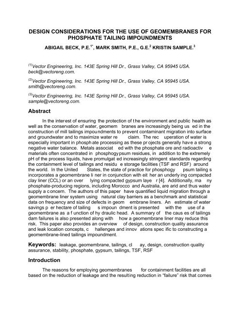
<strong>DESIGN</strong> <strong>CONSIDERATIONS</strong> <strong>FOR</strong> <strong>THE</strong> <strong>USE</strong> <strong>OF</strong> GEOMEMBRANES <strong>FOR</strong><br />
PHOSPHATE TAILING IMPOUNDMENTS<br />
ABIGAIL BECK, P.E. 1* , MARK SMITH, P.E., G.E. 2 KRISTIN SAMPLE. 3<br />
(1) Vector Engineering, Inc. 143E Spring Hill Dr., Grass Valley, CA 95945 USA.<br />
beck@vectoreng.com.<br />
(2) Vector Engineering, Inc. 143E Spring Hill Dr., Grass Valley, CA 95945 USA.<br />
smith@vectoreng.com.<br />
(3) Vector Engineering, Inc. 143E Spring Hill Dr., Grass Valley, CA 95945 USA.<br />
sample@vectoreng.com.<br />
Abstract<br />
In the interest of ensuring the protection of t he environment and public health as<br />
well as the conservation of water, geomem branes are increasingly being us ed in the<br />
construction of mill tailings impoundments to prevent contaminant migration into surface<br />
and groundwater and to maximize water re claim. The rec uperation of water is<br />
especially important in phosph ate processing as these pr ojects generally have a strong<br />
negative water balance. Metals associat ed with the phosphate ore and radioactiv e<br />
materials often concentrated in phosphogypsum residues, in addition to the extremely<br />
pH of the process liquids, have promulgat ed increasingly stringent standards regarding<br />
the containment level of tailings and residu e storage facilities (TSF and RSF) around<br />
the world. In the United States, the state of practice for phosphogy psum tailing s<br />
incorporates a geomembrane li ner in conjunction with eit her an underly ing compacted<br />
clay liner (CCL) or an over lying compacted gypsum laye r [4]. Additionally, ma ny<br />
phosphate-producing regions, including Morocco and Australia, are arid and thus water<br />
supply a c oncern. The authors of this paper have quantified liquid migration through a<br />
geomembrane liner system using natural clay barriers as a benchmark and statistical<br />
data on frequency and size of defects in geom embrane liners. An estimate of water<br />
savings p er hectare of tailing s impoun dment is presented with the use of a<br />
geomembrane as a f unction of hy draulic head. A summary of the caus es of tailings<br />
dam failures is also presented along with how a geomembrane liner may reduce this<br />
risk. This paper also provides an overview of design, construction quality assurance<br />
and leak location concepts, c hallenges and innov ations spec ific to constructing a<br />
geomembrane-lined tailings impoundment.<br />
Keywords: leakage, geomembrane, tailings, cl ay, design, construction quality<br />
assurance, stability, phosphate, gypsum, tailings, TSF, RSF<br />
Introduction<br />
The reasons for employing geomembranes for containment facilities are all<br />
based on the reduction of leakage and the resulting reduction in “failure” risk that comes
with better containment; with the definition of “failure” including structural failure,<br />
environmental contamination a nd inadequate water supply. Whether for the protection<br />
of surface and groundwater or t he optimiz ed water reclaim, geomembranes are ofte n<br />
the most cost-effective way to drastically reduce lea kage from containme nt facilities ,<br />
especially when cost is considered from a risk-based net present value (NPV), or risked<br />
NPV, approach. In fact, no modern large-scale leach pads us e soil-only liners and this<br />
is often driven as much by ec onomics as en vironmental factors [1], as the v alue of the<br />
solution itself lost through clay liners can pay for the extra cost of constructing with a<br />
geomembrane as well as the cost of proper construction quality assurance (CQA) [5].<br />
The most common types of geomembrane ty pically used in th e mining industry<br />
are high density poly ethylene (HDPE), linear low density polyeth ylene (LLDPE) and<br />
polyvinyl chloride (PVC). These products are listed in order of inc reasing flexibility and<br />
decreasing strength. The thicknesses of the both types of pol yethylene (PE) liners<br />
typically run from 1.0 to 2.0 mm, while PVC is ty pically 0.50 to 1.0 mm thick [1].<br />
Geomembrane installations can be a si ngle lay er of geomembrane on prepared<br />
subgrade, two layers of geomembrane for addition p rotection, reduced head on the<br />
secondary liner and the added benefit of leak detection capabilities , or it can be a<br />
geomembrane over a low-per meability soil laye r, referred to as a composite lining<br />
system.<br />
The performance of the final, install ed geomembrane product is not only a<br />
function of the design but also the quality control measures taken up until the beginning<br />
of the geomembrane service life. G eomembranes are produc ed using stric t<br />
manufacturing quality assurance (MQA) programs, starting with the resin that the sheets<br />
are made out of and cont inuing until the rolls have arrived on site. The inst allation of<br />
the material is guided by CQA practice s such as making sure that each welding<br />
machine has been set up correctly and trial welds hav e been performed, each weld is<br />
logged, each panel that is placed can be tracked through a syst em of panel numbers ,<br />
each seam is tested for leaks through air pressure and vacuum box testing, and that the<br />
seam strengths produced in the field meet design specificat ions. CQA is not required<br />
by regulation in most countri es, but statistics show a sign ificantly greater number of<br />
holes per hectare and a higher rate of system failure when a CQA program is not in<br />
place [2]. An additional le vel of quality control would be to perform a geoelectric leak<br />
detection s urvey on t he installed geomem brane. A leak detection survey can chec k<br />
100% of the lined area for leaks present bot h before and after any cover soil placement<br />
(often a thin lay er of gypsum in the case of phosphogypsum residues). This method<br />
uses electricity to pinpoint sources of cu rrent flow r esulting from holes through the<br />
geomembrane.<br />
1. Leakage Analysis<br />
1.1 Method and Assumptions<br />
In order to quantify the leakage that c an be av oided through the use of<br />
geomembranes, a simplified com parative analys is was performed. This analys is is<br />
meant to provide a comparis on between lined and unlined taili ngs facilities located on<br />
sites with naturally occurring clay of varying thicknesses of 1, 3 and 10 meters with
saturated flow conditions. The potential leakage was estimated for sites underlain by<br />
clay and c ompared to the potential leak age if a geomembrane is installed over those<br />
same clay thicknesses. The Giroud equation was used to calculate the leakage through<br />
a composite liner system [3]. Darcy’s law (and the assumption of saturated steady-state<br />
flow) was used to c alculate leakage through CCL and natural c lay containment. Head<br />
depths of 1 through 20 meters w ere used in the analysis and the clay was assumed to<br />
have a hydraulic conductivity of 1 x 10 -7 cm/sec. For the purposes of this an alysis, the<br />
effects of slurry consolidation were not taken into consideration.<br />
In order to calculate t he leakage through a geomembrane or composite liner, the<br />
hole s ize and frequency must be estimated; these vary with the thickness of the<br />
geomembrane and the quality of t he installation [2]. Theoretically , a geomembrane can<br />
be installed leak free if all measures are taken to control the quality, but due to site<br />
conditions and human error, this is essent ially never the case for large-scale<br />
installations. For all practical purposes, even with the highest level of CQA, there will be<br />
some defects or leaks. To model this im perfection the leakage is estimated by three<br />
categories of liner installation; high quality, average quality and low quality. High quality<br />
represents an excellent liner installation and CQA progr am, along with a geoelectric<br />
leak detection survey. Aver age quality represents a liner in stalled with a CQA program<br />
of average quality. Low quality represents a liner installed with either a poor CQ A<br />
program or the lack thereof. The hole frequencies and sizes fo r each tier of installation<br />
quality (as shown in Table 1) are bas ed on published values and the authors’<br />
professional experience [2]. The holes we re ass umed to be circular, with av erage<br />
contact quality with the subgrade, and the geomembrane was assumed to be 1.5mm<br />
thick HDPE as this is the most commonly used geomembrane in mining applications.<br />
Table 1. Hole Frequencies and Sizes<br />
1.3 Results and Discussion<br />
The following tables s how the results of t he leakage r ate calculations for a compacted<br />
clay liner (CCL) of 1 m thickness, natural clay containment of 3m and 10 m thicknesses,<br />
and geomembrane liners of vari ous installation qualities (see Table 1). For simplicity,<br />
the permeability of the natural clay containment and CCL were assumed equal and both<br />
systems were assumed to be fully saturated.
Table 2. Leakage Rates for a 1-meter thick compacted clay liner<br />
Table 3. Leakage Rates for 3 meters of natural clay containment<br />
Table 4. Leakage Rates for 10 meters of natural clay containment<br />
The leakage analys is shows that the in stallation of a geomembrane significant ly<br />
reduces the liquid losses through the bottom of a containment facility, especially when a<br />
thick layer of clay is not present under the s ite. This approach gives a rough idea of the<br />
potential water savings when a geomembrane is em ployed in a tailings impoundment<br />
design. An important note regarding geomem brane liners with “low quality”<br />
installations: data and in-house surveys suggest that over 30% of such systems<br />
experience a failure that requires either a substantial reconstruction or complete<br />
replacement (or abandonment) of the system and th is is not reflected in the leak age<br />
figures reported in the preced ing tables (the failure r ate of systems with “ average” or<br />
“high” is negligible).<br />
2. Design Considerations<br />
Designing with geomembranes is a specia lized field wit hin geotechnica l<br />
engineering, which is typically based on t he strength of soils. In addition to the
consideration of the engineerin g properties of soils, a des ign must also consider the<br />
engineering properties of geomembranes and how the soil and geomembrane interact.<br />
Anchor trenches are required t o keep the geomem brane from slipping d own<br />
slopes. Fo r a tailin gs impoundment, an anc hor trench would be install ed in the starter<br />
embankment. As the embankments rise, a se cond phase of liner would be welded on<br />
to the lower geomembrane and it would be extended up over the new embankment.<br />
Since water is prevented from migrati ng through the bottom liner by using a<br />
geomembrane, internal drainage within the tailings impoundment becomes an important<br />
component of the design. A drainage system along the fl oor of a lined tailings<br />
impoundment provides several geotechnical and water recovery benefits. By allowing<br />
water to drain from belo w the tailin gs, cons olidation occurs more rapidly by having<br />
double-drainage. As the taili ngs consolidate, the densit y increases which also<br />
increases the shear strength, wh ich improves stability. This increase in de nsity als o<br />
allows for a greater amount of tailings storage within the same impoundment volume.<br />
A drainage system also helps maintain a low phreatic surface within the<br />
impoundment. Lowering the phreatic surface dec reases the risk of liquefaction, wh ich<br />
has been t he cause of many taili ngs dam failures. It also decr eases the potential fo r<br />
internal piping or er osion of t ailings ma terial used for dam construction. Seepage<br />
losses through the liner are also reduced by the lower phreatic surface. As an<br />
additional benefit, the drainage syst em also allows for faster wa ter recovery from the<br />
impoundment for use in the processing plan t, thereby reducing water makeup demand<br />
from alternative sources.<br />
High quality containment syst ems reduce the risk of structural failure due to a<br />
number of favorable factor s. The seepage in the embankment and foundation is<br />
significantly reduced (often by 2 orders of magnitude), thus improving the stability of the<br />
slopes and the risk of internal erosion (or “piping”) failure; the latter, loss of fines b y<br />
migration in seepage waters, is the cause of many dam failures including the well kn ow<br />
cases of Los Frailes (Spain) an d Omai (G uyana). A recent survey of tailings d am<br />
failures by the authors’ firm considered 122 documented failures and found the following<br />
trigger modes: seepage alone was the primary caus e in 14% of the failures, slope<br />
instability 30%, foundations 11% , and earthquakes 20%. Slope instability, foundation<br />
failures and earthquake respons e are all s ignificantly and negatively affected by higher<br />
phreatic surfaces in the em bankment and foundation. Thus, a t otal of 75% of these<br />
failures were directly related to seepage an d all would have been significantly less likely<br />
- and most probably avoided - with a good quality li ner system. A liner s ystem also<br />
allows the dam to be more aggressively designed; using steeper slopes, less<br />
complicated (and les s expensiv e) embankm ent fill and drainage systems and simpler<br />
construction methods, which can offset the cost of the liner. Taken in total, conventional<br />
tailings disposal presents one of the highes t risks in mining and c onsidering this in the<br />
design is well advised [7, 8].
Conclusions<br />
If design concerns include env ironmental degradation, water conservation or<br />
reduction of risk, then employing a geomembrane in the design of a tailings or residue<br />
storage facility cou ld signific antly improve its performance. As illustrated by a<br />
quantitative comparative analysis of leakage rates, constructing a tailin gs impoundment<br />
with a geomembrane can reduce leakage by up to 99% in sites with thin clay layers and<br />
up to 94% in sites with up to ten meters of clay. In addition, the risk of failure is<br />
mitigated, substantially elimi nating 75% of the cause of most tailings dam failures.<br />
Using average or high quality installation techniques further reduces the risk of failure of<br />
the geomembrane liner by at least 30%.<br />
References<br />
[1] Breitenbach, A. J. and Smith, M.E., “Overview of geomembrane history in the mining<br />
industry”, 8ICG Conference Proceedings, 2006.<br />
[2] Forget, B., Rollin, A.L. and Jacquelin, T. “Lessons Learned fr om 10 Years of Lea k<br />
Detection Surveys on Geomembranes”, Sardinia Symposium, 2005.<br />
[3] Giroud, J.P., King, T.D., Sanglerat, T.R., Hadj-Hamou, T. and Khir e, M.V. “Rate of<br />
Liquid Migration Through defects in a Geomembrane Placed on a Semi-Pe rmeable<br />
Medium,” Geosynthetics International, Vol. 4, Nos. 3-4, pp. 349-372. 1997.<br />
[4] Florida Department of Environment al Protection (FDEP) . “Phosphogypsum<br />
Management Rules, F.A.C. Chapter 62-673”, 1994.<br />
[5] Thiel, R., Beck, A. and Smith, M. “The Value of Geoelectric Leak Detection Services<br />
for the Mining Industry”, Geofrontiers Conference Proceedings, 2005.<br />
[6] U.S. Environmental Protection Agency. “T he Feas ibility of Linin g Tailings Ponds”.<br />
Office of Solid Waste, January 1997.<br />
[7] Leduc, M. Backens, M. and Smith, M. E. “Tailings Co-Disposal TM at the Esquel Gold<br />
Mine, Patagonia, Argentina,” proceedings of the symposium on Sustainable<br />
Development, Annual Meeting SME, Denver, Co, Feb. 2004.<br />
[8] Smith, M. E. and Leduc, M. “Tailings Co-Disposal TM Innov ations for Cost Sav ings<br />
and Liability Reduction proceedings of the XXVI Convención Minera of the Instituto<br />
de Ingenieros de Minas del Perú, Sept. 2003.<br />
________________________________<br />
Presented at the 3rd International Conference on the Valorization of Phosphates and<br />
Phosphorus Compounds (COVAPHOS III) in Marrakech, Morocco, March 18-20, 2009