LINER INTEGRITY SURVEY GENERAL GUIDE - Geosynthetica
LINER INTEGRITY SURVEY GENERAL GUIDE - Geosynthetica
LINER INTEGRITY SURVEY GENERAL GUIDE - Geosynthetica

You also want an ePaper? Increase the reach of your titles
YUMPU automatically turns print PDFs into web optimized ePapers that Google loves.
<strong>LINER</strong> <strong>INTEGRITY</strong> <strong>SURVEY</strong><strong>GENERAL</strong> <strong>GUIDE</strong>JULY 2013
Liner Integrity SurveyGeneral GuideTABLE OF CONTENTS1.0 HANDBOOK INSTRUCTIONS ............................................................................. 12.0 BARE GEOMEMBRANE <strong>SURVEY</strong>S .................................................................... 12.1 Water Puddle Method (ASTM D7002)................................................................ 12.2 Water Lance Method (ASTM D7703)................................................................. 12.3 Conductive Geomembrane Spark Testing Method (ASTM D7240).................... 12.4 Arc Testing Method (ASTM in development)...................................................... 23.0 COVERED GEOMEMBRANE <strong>SURVEY</strong>S............................................................. 23.1 Dipole Method – Soil Covered Geomembrane (ASTM D7007).......................... 23.2 Dipole Method – Water Covered Geomembrane (ASTM D7007) ...................... 6ATTACHMENTSAttachment 1:Attachment 2:Attachment 3:BLIND ACTUAL LEAK PROTOCOLDESIGNING FOR <strong>LINER</strong> <strong>INTEGRITY</strong> <strong>SURVEY</strong>SELECTRICAL <strong>LINER</strong> <strong>INTEGRITY</strong> <strong>SURVEY</strong> OPERATORCERTIFICATION© 2013 TRI Environmental, Inc. All Rights Reserved-i-
Liner Integrity SurveyGeneral Guide1.0 HANDBOOK INSTRUCTIONSThis handbook is intended for use by design engineers, regulatory agencies, construction qualityassurance agencies, and any individuals seeking a basic knowledge of liner integrity surveys. It is not acomprehensive guide for the performance of liner integrity surveys. It describes the most commonly usedmobile liner integrity / leak location methods.For more specific information related to your project, contact Abigail Beck, TRI Environmental Director ofLiner Integrity Services, at abeck@tri-env.com, 512-623-0511. TRI Environmental is a world-wideeducational and service platform for liner integrity and leak location surveys. TRI performs liner integritysurveys, provides liner integrity survey equipment, refers liner integrity companies world-wide, andprovides technician training and certification.2.0 BARE GEOMEMBRANE <strong>SURVEY</strong>SReferences:ASTM D7002: Standard Practice for Leak Location on Exposed Geomembranes Usingthe Water Puddle SystemASTM D7703: Standard Practice for Electrical Leak Location on ExposedGeomembranes Using the Water Lance SystemASTM D7240: Leak Location using Geomembranes with an Insulating Layer in IntimateContact with a Conductive Layer via Electrical Capacitance Technique (ConductiveGeomembrane Spark Test)2.1 Water Puddle Method (ASTM D7002)The water puddle method is generally the preferred method for bare, non-conductive geomembrane dueto its speed and sensitivity, but it becomes less sensitive on extreme side slopes. When slopes aresteeper than 2H:1V, the water lance method should be used. The minimum sensitivity is a 1 mmdiameter leak.A low voltage direct current source is introduced to the water sprayed above the geomembrane andgrounded to the subgrade underneath the geomembrane. An ammeter in series with the circuit convertsthe increase in voltage to an audible signal when the equipment passes over a leak.The water sprayed onto the survey area to perform the test must be contained in the survey area (abovethe geomembrane to be tested). Conductive features such as concrete sumps and batten strips must beisolated and cannot be tested, since they will ground out the survey (give a false positive signal).2.2 Water Lance Method (ASTM D7703)The water lance method is generally the preferred method for bare, non-conductive geomembrane whenslopes are steeper than 2H:1V, but it can also be used on flat areas. The minimum sensitivity is a 1 mmdiameter leak.A low voltage direct current source is introduced to the water sprayed above the geomembrane andgrounded to the subgrade underneath the geomembrane. An ammeter in series with the circuit convertsthe increase in voltage to an audible signal when the equipment passes over a leak.The water sprayed onto the survey area to perform the test must be contained in the survey area (abovethe geomembrane to be tested). Conductive features such as concrete sumps and batten strips must beisolated and cannot be tested, since they will ground out the survey (give a false positive signal).2.3 Conductive Geomembrane Spark Testing Method (ASTM D7240)The conductive geomembrane spark testing method is generally preferred for bare conductive© 2013 TRI Environmental, Inc. All Rights Reserved1
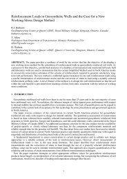
Liner Integrity SurveyGeneral Guidegeomembranes, since no water is required to perform the test. The minimum sensitivity is a 1 mmdiameter leak per current ASTM but pinholes can be found.A high voltage pulsed power supply charges a capacitor formed by the underlying conductive layer, thenon-conductive layer of the geomembrane and a coupling pad. The area is swept with a brush-like testwand to locate points where the capacitor discharges through a leak. When the system senses thedischarge current, it is converted into a visible spark and an audible alarm.The surface of the geomembrane must be clean and dry. Unless the conductive geomembrane has beeninstalled with the conductive layer sufficiently broken in the fusion weld, this method cannot be used totest fusion-welded seams.2.4 Arc Testing Method (ASTM in development)The arc testing method is generally preferred for bare geomembranes, since no water is required toperform the test and equipment is available with an optional GPS-based data acquisition system. Theminimum sensitivity is a pinhole leak.A high voltage power supply is applied to a test wand above the geomembrane and is grounded to theunderlying conductive layer. The area is swept with a test wand and an electrical arc is formed in thepresence of a leak. When the system senses the discharge current arc, it is converted into visual andaudio alarms. The test wand can be custom sizes and shapes for specific applications.This type of test requires that the geomembrane is in contact with the subgrade. If the separationdistance is greater than 3 cm, the instrument is not likely to arc. In addition, no water can be present ontop of the geomembrane.The surface of the geomembrane must be clean and dry.3.0 COVERED GEOMEMBRANE <strong>SURVEY</strong>SReferences:ASTM D7007: Standard Practices for Electrical Methods for Locating Leaks inGeomembranes Covered with Water or Earth Materials3.1 Dipole Method – Soil Covered Geomembrane (ASTM D7007)This dipole method is used for geomembranes covered with earth, gravel, concrete, sand or any otherconductive medium. The sensitivity of the survey depends highly on site conditions and the lining systemmaterials. The suggested minimum sensitivity for earthen materials less than 0.6 meters thick is a 6.4mm diameter leak, though adverse site conditions can decrease the sensitivity.A high voltage is applied to the cover material with a positive electrode. The power source is grounded tothe subgrade underneath the geomembrane. Voltage measurements are taken in a grid patternthroughout the survey area using a dipole instrument. Leak locations cause a sine wave pattern in thevoltage measurements as the dipole instrument travels across a hole location.The survey area must be electrically isolated from the surrounding ground. Generally, a perimeterisolation trench surrounds the survey area, with the geomembrane exposed. Any conductive objectssuch as access roads, metal sump pipes, or standing water must be removed before the survey can beperformed.Leaks can be located in real time as the survey progresses, or the data can be recorded quickly anddownloaded into computer software for analysis. Currently, the ASTM requires the data to be recordedbut does not specify how it is analyzed. Data can be analyzed two-dimensionally or three-dimensionally.Two-dimensional data analysis displays the data as voltage slices of the survey area, as graphed insoftware such as Excel. Three-dimensional data analysis shows the voltage measurements in plan viewof the survey area. An example of data taken in a small test cell and shown graphically using both dataanalysis methods is shown in Figure 1.© 2013 TRI Environmental, Inc. All Rights Reserved2
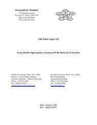
Liner Integrity SurveyGeneral GuideA sensitivity test is performed before beginning the survey using either a real or an artificial leak. Anartificial leak is essentially a metal disk of a given diameter to mimic an actual leak. The metal disc isgrounded to the conductive layer underlying the geomembrane. The distance from the artificial leakground and the power source ground should be an adequate distance to mimic an actual leak. Thesensitivity test protocol requires that the magnitude of the sine wave signal produced by the real orartificial leak be at least three times that of the background voltage oscillations as measured when theleak is not there. This is known as the signal to noise ratio. A sample of sensitivity test results are shownin Figure 2.Once a leak is located by the survey, it must be excavated and the leak cleaned off and removed from theelectrical circuit so that the area around the leak can be checked for leaks in the surrounding area, sincelarge leaks can mask smaller adjacent leaks.© 2013 TRI Environmental, Inc. All Rights Reserved3
Liner Integrity SurveyGeneral GuideFigure 1: Two-Dimensional (top) and Three-Dimensional (bottom) Data Analysis of a Small Survey Area.The obvious leak location is shown as a sine wave pattern on slice number three of the two-dimensionaldata and can be seen in plan view as a negative (red/blue) circular peak next to a positive (green/yellow)circular peak separated by tight voltage potential lines in the three-dimensional data plot. A second,much smaller leak signal can be seen on slice number 1 of the three-dimensional plot (center of slice),but cannot be distinguished from the background voltages on the two-dimensional plot.© 2013 TRI Environmental, Inc. All Rights Reserved4
Liner Integrity SurveyGeneral GuideTable 1: Dipole Survey Methodology ComparisonMethod Pros ConsReal-Time Leak LocationData Recording: 2-D DataAnalysisData Recording: 3-D DataAnalysis-Does not require sophisticateddata recording software-Does not require highprecisionGPS-Faster than real-time leaklocation-Provides quality controldocumentation-Does not require high level ofoperator skill with senior reviewof data-Faster than real-time and 2-Ddata analysis-Measurement locations highlyaccurate due to GPS-guidedgrid lines-Leak locations highly accuratedue to high-precision GPS-Provides meaningful qualitycontrol documentation-Does not require high level ofoperator skill with senior reviewof data-Requires high level of operatorskill-Survey progresses slowly-No quality control documentation-Relies on string lines formeasurement accuracy-to be in accordance with currentASTM, must record data by handor other method even though it willnot be evaluated-Quality control documentation notmeaningful-Difficult to relocate leak locationsfrom data because there areimprecise spatial references-Relies on string lines formeasurement accuracy-Requires high-precision GPS andsophisticated data recordingsoftware© 2013 TRI Environmental, Inc. All Rights Reserved5
Liner Integrity SurveyGeneral GuideFigure 2: A Sensitivity Test, also known as a Calibration Curve. The graph shows the sine wave patternproduced by an artificial leak. In this case, the signal to noise ratio is 12.3.2 Dipole Method – Water Covered Geomembrane (ASTM D7007)This survey setup and methodology is essentially the same as the soil-covered survey method. Thesame data recording and analysis techniques can be used, but the ASTM does not require data recordingfor water-covered geomembranes. The minimum sensitivity for water-covered geomembrane is a 1.4 mmdiameter leak. Although the ASTM specified minimum sensitivity of this method is lower than thatspecified for the water puddle and water lance methods, this methods is typically more sensitive than theaforementioned methods due to the hydraulic head over leak locations, which provides better holecontact.Rather than taking voltage measurements at discrete points throughout the survey area, the voltage iscontinuously measured by an analog-based voltmeter. When the voltage increases beyond a giventhreshold, with either a positive or negative magnitude, an audible tone alerts the operator. Theequipment is swept along the survey area in lines throughout the survey areaThe sensitivity test consists of finding the “minimum detectable distance” that the equipment can be sweptby the artificial or actual leak with the target diameter. This minimum detectable distance dictates thespacing of the survey lines. No signal to noise ration calculation is required.© 2013 TRI Environmental, Inc. All Rights Reserved6
Liner Integrity SurveyGeneral GuideIt should be noted that a dipole survey in a highly conductive solution such as brine or with poor boundaryconditions that cannot be changed is considerably more complicated than in fresh water with goodboundary conditions and requires more advanced geophysical survey methodology.© 2013 TRI Environmental, Inc. All Rights Reserved7
ATTACHMENT 1BLIND ACTUAL LEAK PROTOCOL
BLIND ACTUAL LEAK PROTOCOLDefinition of Blind Actual Leak – A hole created through the geomembrane in the survey area by a siteowner, CQA agency or design engineer to check the effectiveness of the liner integrity surveyLeak detection is dependent upon the site conditions at each leak. Site conditions that affect leakdetection sensitivity (particularly for surveys with earth materials on the geomembrane, to some degreewith surveys on bare geomembranes) include:- having adequate moisture throughout the overburden material and near-subgrade,- moisture in the leak,- the presence of dry insulating materials such as geotextile or geonet in contact with the leak,- contact of the geomembrane with the overburden and subgrade,- degree of isolation of the overburden from earth ground or the conducting material under thegeomembrane, and- the composition of the material in contact with the liner (large stones may bridge a leak)Because of these varying site conditions, detecting a leak of the same size as the actual leak used todetermine the leak detection sensitivity (calibration) as specified in the ASTM standards could beproblematic. Better leak detection sensitivity will be obtained at some locations, and worse leak detectionsensitivity will be obtained at other locations. It should be noted that for knife slits which fold backtogether and thus create a “barrier” the likelihood for leak detection during the leak detection survey isrelatively small.Guidelines for installing blind actual leaks1. The blind actual leaks are to be installed in accordance with the relevant ASTM standard for thetype of geomembrane leak location survey being performed. Specifically, the blind actual leak isconstructed by drilling a hole in the installed bare geomembrane that is to be tested. The holeshall be drilled, and the drill bit moved forward and backward in the hole so the geomembranematerial is removed rather than just displaced.2. The blind actual leaks should be installed as early as practical before the geomembrane leaklocation survey is performed so the blind test leak will be exposed to the same conditions ofrainfall, condensation, consolidation, and equilibrium as the rest of the geomembrane in theinstallation. If the blind actual leaks cannot be installed during geomembrane installation, it isstrongly recommended that the diameters of the blind actual leak are increased to twice thesuggested minimum diameter.3. The locations of the blind actual leaks are documented using appropriate land surveying methodsso the blind actual leaks can be located for future repair.4. The blind actual leaks shall be put in realistic locations and not on wrinkles, areas of bridging, orother areas where the geomembrane is not in contact with the subgrade, or within 15 m of theedge of the liner. If conductive geomembrane is used, the blind actual leak can be located in apoor contact situation.5. The blind actual leaks shall be backfilled with a compaction representative of the rest of theinstallation. Ensure that any cavity made by the drill in the subgrade under the blind actual leak isfilled with soil, unless conductive geomembrane is being tested.6. The number of placed blind actual leaks should be reasonable. The Owner or owner’srepresentative should consider the cost of installing, surveying, documenting, and repairing theblind actual leaks and the fact that a repair weld or patch of inferior integrity will replace anunflawed geomembrane.7. In summary, for the leak location survey to successfully detect the intentionally placed blindactual leaks, the blind actual leaks should have conductivity through the openings otherwise itmay not be detected. If the owner or owner’s representative has their own independent leaklocation equipment, the blind actual leaks could be verified as they are being placed.
8. As a courtesy to the leak location survey contractor the owner or owner representative shouldmention at the start of the survey that a blind actual leak has been placed in accordance with thisguidance document.Guidance if the blind actual leak is not detectedIf the leak location survey contractor does not detect a blind actual leak after surveying an area where theblind actual leak was placed, then the owner or owner representative should mention that a blind actualleak was not detected. The leak location survey contractor shall review the survey data to determine if theblind actual leak signal is indicated in the survey data. In addition, the leak location survey contactor shallconfirm that the survey successfully completed the leak detection sensitivity tests (calibration) per thecorresponding ASTM procedure and that the survey was performed according to the ASTM procedure.Assuming the blind actual leak was not detected (even after review of the survey data) then the followingpotential limitations should be considered for each missed blind actual leak:-Subgrade restrictions (conductivity, moisture content, etc.),-Proximity to survey boundary,-Geosynthetics underneath or above the geomembrane,-Uncovered material restrictions (waves, wrinkles, etc.),-Cover material restrictions (conductivity, water saturation, etc.),-Water requirement (depth necessary, quantity of water needed, bottom slope), and-Proximity to protruding/penetrating accessories (pipes, steel bars, access platforms, ladders, etc.).If any of the preceding conditions apply, the blind actual leak was not placed per the procedures of therelevant ASTM standardIf it can be demonstrated that the placed blind actual leak was not detectable because of the aboveconsiderations or other limitations and a detailed check with the leak location equipment shows that thereis no electrical conductivity through the blind actual leak then the blind actual leak was in fact neverdetectable with that particular leak detection setup and indicates a limitation of the leak location survey.If the leak location survey contractor locates leaks before and after missing a blind actual leak and thelocated leaks are smaller than the blind actual leak then it is assumed that site conditions at the blindactual leak location are not optimal. The leak location survey contractor shall potentially recommend tothe owner or their representative what site conditions can be improved or changed so detection of theblind actual leaks can be improved.If the survey is ongoing for multiple days, it is recommended to review relevant ASTM procedures toassure that the leak detection sensitivity test (calibration) was implemented correctly, For example thesurvey spacing could be optimized in accordance with relevant ASTM standards. Alternatively, the sizeof the placed blind actual leak for the remainder of the survey can be increased to account for poor siteconditions.
ATTACHMENT 2DESIGNING FOR <strong>LINER</strong> <strong>INTEGRITY</strong><strong>SURVEY</strong>S
DESIGNING FOR <strong>LINER</strong> <strong>INTEGRITY</strong> <strong>SURVEY</strong>S<strong>GENERAL</strong> <strong>GUIDE</strong>APRIL 2013
Designing for Liner Integrity SurveysGeneral GuideTABLE OF CONTENTS1.0 HANDBOOK INSTRUCTIONS ............................................................................. 12.0 BOUNDARY CONDITIONS .................................................................................. 13.0 MATERIAL SPECIFICATIONS............................................................................. 13.1 Geomembranes ................................................................................................. 13.2 Geocomposites .................................................................................................. 13.3 Geotextiles ......................................................................................................... 23.4 Geosynthetic Clay Liners (GCL)......................................................................... 23.5 Cover Material.................................................................................................... 33.6 Subgrade Material.............................................................................................. 34.0 CONSTRUCTION SEQUENCING ........................................................................ 34.1 Dipole Method – Soil Covered Geomembrane (ASTM D7007).......................... 34.2 Dipole Method – Water Covered Geomembrane (ASTM D7007) ...................... 34.3 Water Puddle and Water Lance Methods (ASTMs D7002 and D7703) ............. 35.0 GROUNDED OBJECTS........................................................................................ 36.0 SPECIFYING METHODS...................................................................................... 46.1 Specifying Leakage Rates ................................................................................. 46.2 Minimum Experience Qualifications ................................................................... 5© 2013 TRI Environmental, Inc. All Rights Reserved-i-
Designing for Liner Integrity SurveysGeneral Guide1.0 HANDBOOK INSTRUCTIONSThis handbook is intended for use by design engineers and earthworks and liner installer contractors. Itdoes not contend to be comprehensive. An experienced liner integrity contractor should review projectspecific construction plans and specifications.2.0 BOUNDARY CONDITIONSThe four critical boundary conditions in order to conduct a liner integrity or leak location survey are:1. Conductive material over geomembrane (unless the geomembrane is bare)2. Conductive material below geomembrane3. Good contact of material above and below geomembrane through leak4. Material above and below geomembrane are only in contact through leak locationsThe following sections describe how these four conditions must be addressed during the design andconstruction of a facility where a liner integrity survey is specified.3.0 MATERIAL SPECIFICATIONS3.1 GeomembranesGeomembranes must be electrically insulative. Polyethylene, polyvinyl chloride, polypropylene,chlorosulfonated polyethylene and bituminous geomembranes are sufficiently electrically insulative.Excessive leakage in terms of number or size of holes in the geomembrane will compromise thesensitivity of a liner integrity survey. Any locations of poor hole contact (wrinkles, subgrade depressions)will decrease the sensitivity of a survey and possibly result in undetected leaks. Material and placementmethods should minimize the production of wrinkles and areas of trampolining.If survey sensitivity is a high concern, conductive geomembrane should be specified. When a material isreferred to as “conductive geomembrane”, it refers to an insulative geomembrane, with a conductive layerbeneath the insulative layer, manufactured specifically to assist liner integrity surveys. The conductivebacking allows leak detection on poor hole contact scenarios and also increases overall leak detectionsensitivity. Conductive geomembrane installation requires a specialty welder and special installationprotocol. GSE’s Leak Location Liner fulfills these requirements.In a double-lined impoundment, a conductive layer must be present under the primary geomembrane. Inthe absence of a conductive layer (i.e. geocomposite only), conductive geomembrane should bespecified.3.2 GeocompositesGeocomposites alone are not conductive, but the application of water to the geocomposite will enable aliner integrity survey. Water can be added to the geocomposite during construction, or after constructionvia rainfall or surface watering, as long as enough water is added to travel down to the geocomposite.With hole contact being an important parameter in survey sensitivity, it can be expected that ageocomposite may increase the minimum detectable hole size.A conductive geotextile can be specified as the geotextile portion of the geocomposite directly in contactwith the geomembrane to be tested in order to enable leak detection.If a non-conductive geomembrane is used as the primary geomembrane in a double-lined impoundmentand a geocomposite is present in the leak detection layer, the leak detection layer must be flooded withwater to perform the survey.© 2013 TRI Environmental, Inc. All Rights Reserved1
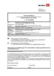
Designing for Liner Integrity SurveysGeneral Guide3.3 GeotextilesGeotextiles alone are not conductive, but the application of water to the geotextile will enable a linerintegrity survey. Water can be added to the geotextile during construction, or after construction viarainfall or surface watering, as long as enough water is added to travel down to the geotextile. If ageotextile is adjacent to moist soil material and covered, the moisture tends to wick through thegeotextile, thus enabling a survey. Geotextiles can be left intact in perimeter isolation trenches as long asthey are dry. In the case of rainfall, it is typically necessary to wait for dry weather for the geotextile to dryout before performing a survey.A conductive geotextile can be specified to be placed underneath the primary geomembrane in a doublelinedimpoundment in order to enable leak detection. The conductive geotextile/geomembrane interfacemay still have contact problems unless the leak location is wet or dirty.3.4 Geosynthetic Clay Liners (GCL)The high quality clay component of a GCL is highly conductive, however due to the discrete clay granulessurrounding by geotextiles, the moisture content of a GCL must be fairly high in order to perform a linerintegrity survey. The minimum moisture content of a GCL required to perform a liner integrity survey canbe estimated at 8%, though this value will vary for different GCL products. A single composite liner withGCL does not require any special preparation; moisture will easily wick into the GCL from the subgrade,since it is extremely hydrophilic. Encapsulated GCL, however, will tend to stay at the moisture contentthat it was placed at. In arid climates where GCL panels are left uncovered and allowed to desiccatebefore being covered with the primary liner, the product can desiccate within one working shift. In aridclimates, it is advisable to either rehydrate the GCL before covering with the primary liner, or specify aconductive geomembrane as the primary geomembrane. Encapsulated GCLs can also have problemswith electrical conductivity over the panel overlaps, especially in arid climates. It is advisable to place abare copper wire in a network under the GCL. The concept of the layout is to run the network of wires sothat each and every panel is connected to at least one wire. The wire is then made accessible to the linerintegrity surveyor by running it out through the anchor trench. At least two discrete wires should beplaced, in order for the liner integrity surveyor to check the conductivity through the bulk of the GCLpanel.Figure 1: Hypothetical copper wire layout for encapsulated GCL. Copper wire is shown as a red line.Copper wire must be accessible to liner integrity surveyor.© 2013 TRI Environmental, Inc. All Rights Reserved2
Designing for Liner Integrity SurveysGeneral Guide3.5 Cover MaterialThe material covering the geomembrane should always be moisture conditioned, unless the project islocated in a wet climate and the material is already sufficiently moist. Highly porous material such asgravel does not require moisture conditioning, since the material will require watering during the leaksurvey regardless. This is only true for large gravel particles (greater than approximately 5 cm). All othermaterials should have moisture within the mass of the cover layer. Surficial watering directly in front ofthe liner integrity survey may be required regardless.3.6 Subgrade MaterialSubgrade conductivity will not be a problem with a compacted clay liner. However, if there is no designrequirement for a compacted clay liner and onsite soils are used, there is a small chance that the materialwill be either too dry or contain a mineral content that is not sufficiently conductive. In that case, thesubgrade material must be watered before placement of the geomembrane. Subgrade conductivitytesting should be performed in the case of questionable site soils, or a conductive geomembrane shouldbe specified as the geomembrane type.Geomembrane rub sheets should not be allowed to remain under the geomembrane.4.0 CONSTRUCTION SEQUENCING4.1 Dipole Method – Soil Covered Geomembrane (ASTM D7007)An isolation trench must be specified as part of construction sequencing around the perimeter of thesurvey area. In climates with spells of extreme rain events, a rain flap should also be considered. Rainflaps are welded in the isolation trenches and propped up by soil so that in the case of extreme rainwhere the trench will fill up with water, electrical isolation will still be provided by the rain flap. The rainflap must be welded to the base geomembrane.Access roads can typically remain in place, as long as there is a strip of geomembrane or rain flapbisecting the access road, creating electrical isolation..4.2 Dipole Method – Water Covered Geomembrane (ASTM D7007)Consideration for the installation of any grounded objects should be given with respect to the constructionsequencing. The survey should be performed before any necessary grounded objects are installed.If a double-lined impoundment lacks a conductive geomembrane for the primary geomembrane or lacks aconductive geotextile underneath the primary geomembrane, the leak detection layer must be flooded inorder to survey the primary geomembrane. There must be ballast over the primary geomembrane, or theimpoundment must be filled with water at the same rate that the leak detection layer is filled (or before)..4.3 Water Puddle and Water Lance Methods (ASTMs D7002 and D7703)Consideration for the direction of flow should be given for bare geomembrane survey methods usingwater as a conductive medium. If water is allowed to flow freely out of the survey area, an electrical shortwill be created. Interim rain flaps can be used where necessary to contain the water within the surveyarea.5.0 GROUNDED OBJECTSObjects that will provide a source of electrical grounding should be carefully designed, or the construction© 2013 TRI Environmental, Inc. All Rights Reserved3
Designing for Liner Integrity SurveysGeneral Guidesequence modified to enable a liner integrity survey. For example, a metal pipe penetrating the linersystem should have a plastic boot so that water sprayed on the geomembrane or soil covering it will nottouch the metal pipe. For pond applications, concrete inlet or outlet structures, including metal battenstrips, will ground out the survey. In some cases the design cannot be modified, but a rain flap can bewelded as an interim measure to intercept water flowing to a grounded object.6.0 SPECIFYING METHODSThe appropriate survey method will depend on the condition of the geomembrane during the survey interms of whether it is bare or covered, whether it is the primary geomembrane or the secondarygeomembrane, and whether the geomembrane has a conductive backing or not. The “Liner IntegritySurvey General Guide” covers the various methods and their general applications.The primary geomembrane of a double-lined impoundment can be surveyed using the dipole with soil ascover if there is ballast material over the primary geomembrane. In that case, the primary geomembranemust be conductive or have a conductive geotextile underneath it, or the leak detection layer must beflooded up to the level of the top of the ballast layer. In order to survey the side slopes, or if there is noballast material over the geomembrane, the impoundment must be completely filled with water and adipole with water as cover method must be performed. Alternatively, conductive geomembrane can bespecified as the primary geomembrane and subsequently any method can be performed on it.A survey can be conducted either before or after cover material placement, or both. The minimumsensitivities of each method, as described in the “Liner Integrity Survey General Guide” should beconsidered. For geomembranes that are to be covered by earthen materials, a survey should beperformed both directly after liner installation and after cover material placement. This will result in themaximum leak detection sensitivity. If small holes are not a concern and only one method can bespecified due to cost constraints, then a dipole survey should be performed after placement of the covermaterials, since this method will locate the major leaks caused by placement of the cover material. Theonly exception to this is if the geomembrane is covered by gravel and the gravel layer can be floodedduring the survey, resulting in the increased sensitivity of a water-covered survey.If a dipole survey is specified, the method of data analysis can be specified. The advantages anddisadvantages of each method of data analysis is described in the “Liner Integrity Survey General Guide”..6.1 Specifying Leakage RatesIt is impossible to construct a “leak free” lining system, since even in the absence of breaches through thegeomembrane, diffusion occurs through a geomembrane. Thus, setting an allowable leakage rate shouldbe attainable with the existing available technologies. Setting an allowable leakage rate too low toachieve with existing technologies is simply a recipe for failure.By using the Bernouilli and Giroud equations, one can calculate the anticipated leakage of a facility.Parameters such as the head over the liner and the hole contact factor can be informed by thegeomembrane application and the geomembrane type. The minimum survey method sensitivity and anassumed undetected leak frequency can be used to inform the number and size of leaks contributing toleakage.With currently available technologies, the lowest level of potential leakage can be achieved by specifyingspecialty conductive geomembrane installed per GSE’s Leak Location Liner installation procedures,performing a bare geomembrane survey directly after geomembrane installation, and then performing thedipole method after the installation of cover material, if applicable. It is technically possible to install ageomembrane without breaches with this prescription, since, if installed and surveyed correctly, iteliminates the known sources of errors in the liner integrity survey technologies. However, room shouldalways be granted for human error to avoid a specification that cannot be met.© 2013 TRI Environmental, Inc. All Rights Reserved4
Designing for Liner Integrity SurveysGeneral Guide6.2 Minimum Experience QualificationsThe various methods vary significantly in how much skill is required to perform them. It is thereforereasonable to set the minimum experience qualifications according to which method is used.Spark testing has been historically performed by liner installers. Very little training is required and nominimum experience in terms of square footage of the method completed is usually required. Once anoperator learns to use the spark tester, very little can go wrong in terms of site conditions and instrumentset up.The arc tester evolved from spark testing technology, but is even easier to use. In less than one hour, anoperator can be competent at performing the arc testing method.The water-based bare liner testing is a little more complicated in terms of setting up the survey, adjustingthe equipment sensitivity and controlling the site conditions so that they do not adversely impact thesensitivity of the survey. It is therefore advisable to set some minimum number of projects and squarefootage where this method has been performed. A reasonable minimum for the water puddle and waterlance methods would be 1-2 projects and a minimum area of 10 hectares.The dipole method is more closely related to advanced geophysical methods, which require a thoroughunderstanding of the method, the equipment, and the site conditions. Many site conditions can adverselyimpact the sensitivity of a survey. It is therefore advisable that the highest level of minimum experiencequalifications be applied to a dipole survey. A reasonable minimum for the dipole method would be 4-5projects and a minimum area of 50 hectares. The minimum qualifications should apply to the leadoperator onsite directing the survey and not the survey company.ELIS Operator certification is available, which can be substituted for the required minimum experiencelevel. The operator certification program requires than an individual performing ELIS methods beevaluated for competency by a third party.© 2013 TRI Environmental, Inc. All Rights Reserved5
ATTACHMENT 3ELECTRICAL <strong>LINER</strong> <strong>INTEGRITY</strong> <strong>SURVEY</strong>OPERATOR CERTIFICATION
ELECTRICAL <strong>LINER</strong> <strong>INTEGRITY</strong> <strong>SURVEY</strong>OPERATOR CERTIFICATIONMAY 2013
Electrical Liner Integrity SurveyOperator CertificationTABLE OF CONTENTS1.0 OPERATOR CERTIFICATION BACKGROUND .................................................. 12.0 THREE-TIERED STRUCTURE............................................................................. 12.1 Level 1 Certification............................................................................................ 12.2 Level 2 Certification............................................................................................ 12.3 Level 3 Certification............................................................................................ 13.0 LEVEL 1 CRITERIA.............................................................................................. 14.0 LEVEL 2 CRITERIA.............................................................................................. 24.1 Written Exam...................................................................................................... 24.2 Field Exam ......................................................................................................... 25.0 LEVEL 3 CRITERIA.............................................................................................. 3© 2013 TRI Environmental, Inc. All Rights Reserved-i-
Electrical Liner Integrity SurveyOperator Certification1.0 OPERATOR CERTIFICATION BACKGROUNDThe operator certification program intent is to uphold industry standards and provide a way of ensuringthat operators are performing the electrical liner integrity survey (ELIS) methods correctly and per ASTMstandard methodology. As the world-wide demand for ELIS grows, the certification program provides atool for emerging ELIS consultants to gain proficiency and credentials. It also provides a tool for siteowners and project engineers and managers to evaluate the capabilities of ELIS providers and establishminimum criteria for the demonstration of competency in the applied ELIS methods.An ELIS Steering Committee was assembled to advise the contents of the operator certification. TheELIS Steering Committee consists of professionals who have worked closely with ELIS methods indifferent roles, especially in method application. Members of the ELIS Steering Committee whospecialize in the application of the ELIS methods are qualified to oversee the field portion of the Level 2certification exam.2.0 THREE-TIERED STRUCTUREThe operator certification program is broken down into three tiers of certification. The intent of the threetiers is to distinguish between the levels of education and practice required in order to illustrate differentlevels of competency. The certification encompasses both bare and covered ELIS methods.2.1 Level 1 CertificationThe first tier of certification illustrates that an individual:1. Is qualified to specify ELIS for projects2. Understands how boundary conditions affect ELIS3. Understands how the ELIS methods are applied4. Is qualified to review ELIS for conformance to ASTM standards2.2 Level 2 CertificationThe second tier of certification illustrates that an individual:1. Has passed a written exam on the application of ELIS methods2. Has passed a field exam on the application of ELIS methods3. Can competently perform ELIS methods per current ASTM standards2.3 Level 3 CertificationThe third tier of certification illustrates that an individual:1. Has satisfied the Level 1 and 2 certification criteria2. Has a proven track record of ELIS method performance3. Maintains certification through a minimum level of annual field experience3.0 LEVEL 1 CRITERIAThe first tier is an educational component. An individual shall receive at least six (6) hours of classroomeducation (or equivalent) in the following subject areas:1. ELIS terminology, history, background© 2013 TRI Environmental, Inc. All Rights Reserved1
Electrical Liner Integrity SurveyOperator Certification2. Electrical Basics3. Bare and covered ELIS methodology4. Criteria for specifying ELIS5. Current ASTM methods for ELIS6. Boundary conditions affecting ELIS performance7. Site safetyAn individual shall receive at least four (4) hours of field training in the following subject areas:1. Operating equipment for bare and covered ELIS methods2. Performing a sensitivity test for bare and covered ELIS methods3. Locating leaks in bare and covered geomembranes4. Setting up a ELIS circuit for bare and covered ELIS methods4.0 LEVEL 2 CRITERIAThe second tier is a demonstration that the Level 1 education and field training can be applied by anindividual. The Field Exam can be conducted to a production survey by an individual.4.1 Written ExamThe written exam, which is administered through a third-party, shall test an individual’s ability to:1. Interpret plans and specifications for ELIS2. Understand electrical measurements3. Perform methods per ASTM standards4. Troubleshoot field difficulties5. Effectively collect and interpret data6. Identify poor boundary conditions7. Understand method limitations4.2 Field ExamThe field exam shall be proctored by a qualified member of the ELIS Steering Committee. The proctorshall observe an individual in the field as the individual performs an ELIS method and without interferingshall document:1. Which method is being performed2. Where electrodes are placed3. Where artificial leak is placed and grounded, if applicable4. What voltage is used for the method5. Survey set up procedures6. Equipment set up and calibration procedures7. Sensitivity test procedures8. Procedures for locating leaks9. Procedures for recording and analyzing data, if applicable© 2013 TRI Environmental, Inc. All Rights Reserved2
Electrical Liner Integrity SurveyOperator Certification10. Any ASTM procedures lacking during field observationThe field exam is method-specific. The documentation of the field exam shall be provided to the ELISSteering Committee. The ELIS Steering Committee shall deliberate on whether the individual hasdemonstrated the ability to locate actual leaks in the field using the applied methodology. If an individualdemonstrates the ability to locate actual leaks, but some aspect of the ASTM procedure is lacking, theELIS Steering Committee shall evaluate whether that lacking procedure was crucial for locating leaks andperforming a thorough survey. The actual location of leaks shall weigh more heavily on the Committee’spass/fail decision than the following of the ASTM standard.The results of the field exam, including critiques and comments from the ELIS Steering Committee, shallbe submitted to the examinee(s) along with a Level 2 certificate if applicable.The ELIS Steering Committee shall maintain a list of all individuals who have passed the written and fieldexaminations and keep on file a copy of the actual examination documentation.5.0 LEVEL 3 CRITERIAThe third tier is a demonstration that the individual can competently perform the ELIS method(s) and hasa proven track record of doing so. Although not necessary to show that an operator can successfullyperform the methods, an owner or design engineer might opt for this level of experience to reduce projectliability. The minimum level of experience is method-specific. The experience for a given method wouldbe called out for a specific project employing that method.For Level 3 certification, the individual must maintain a minimum level of ELIS method performance on anaverage annual basis as follows:1. Bare geomembrane arc testing method: 1 project and 0.4 hectares (1 acre)2. Bare geomembrane spark testing method: 1 project and 0.4 hectares (1 acre)3. Bare geomembrane water puddle method: 1 project and 2 hectares (5 acres)4. Bare geomembrane water lance method: 1 project and 2 hectares (5 acres)5. Water-covered geomembrane dipole method: 2 projects and 4 hectares (10 acres)6. Soil-covered geomembrane dipole method: 2 projects and 25 hectares (25 acres)An excess of survey experience one year can carry into the next year, but no longer than three years pastthe date of the qualifying experience.In order to receive level 3 certification, an individual must submit documentation of the aforementionedexperience requirements to the ELIS Steering Committee. The documentation required shall consist of:1. The name of the project2. The method applied3. Sensitivity test set up and results4. Number and size of located leaksThe ELIS Steering Committee shall maintain an actively updated list of all individuals who maintaincurrent level 3 certification, and which method the certification applies to.© 2013 TRI Environmental, Inc. All Rights Reserved3