Santon Premier Plus Installation Guide - Advanced Water
Santon Premier Plus Installation Guide - Advanced Water
Santon Premier Plus Installation Guide - Advanced Water

Create successful ePaper yourself
Turn your PDF publications into a flip-book with our unique Google optimized e-Paper software.
3.0 INSTALLATION – GENERAL<br />
(FIGS 3 & 5)<br />
3.1 PIPE FITTINGS<br />
All pipe fittings are made via 22mm compression<br />
fittings directly to the unit. The fittings are threaded<br />
3/4”BSP male parallel should threaded pipe connections<br />
be required.<br />
3.2 COLD FEED<br />
A 22mm cold water supply is recommended however,<br />
if a 15mm (1/2”) supply exists which provides sufficient<br />
flow this may be used (although more flow<br />
noise may be experienced).<br />
A stopcock or servicing valve should be incorporated<br />
into the cold water supply to enable the <strong>Santon</strong> <strong>Premier</strong><br />
<strong>Plus</strong> and its associated controls to be isolated<br />
and serviced.<br />
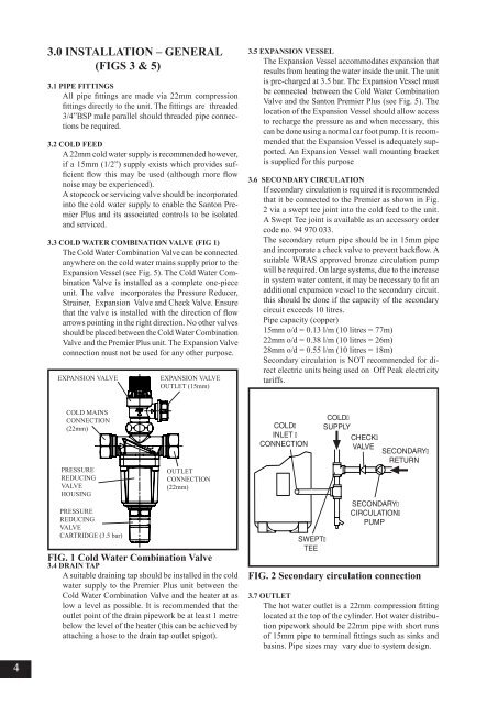
3.3 COLD WATER COMBINATION VALVE (FIG 1)<br />
The Cold <strong>Water</strong> Combination Valve can be connected<br />
anywhere on the cold water mains supply prior to the<br />
Expansion Vessel (see Fig. 5). The Cold <strong>Water</strong> Combination<br />
Valve is installed as a complete one-piece<br />
unit. The valve incorporates the Pressure Reducer,<br />
Strainer, Expansion Valve and Check Valve. Ensure<br />
that the valve is installed with the direction of flow<br />
arrows pointing in the right direction. No other valves<br />
should be placed between the Cold <strong>Water</strong> Combination<br />
Valve and the <strong>Premier</strong> <strong>Plus</strong> unit. The Expansion Valve<br />
connection must not be used for any other purpose.<br />
EXPANSION VALVE<br />
EXPANSION VALVE<br />
OUTLET (15mm)<br />
3.5 EXPANSION VESSEL<br />
The Expansion Vessel accommodates expansion that<br />
results from heating the water inside the unit. The unit<br />
is pre-charged at 3.5 bar. The Expansion Vessel must<br />
be connected between the Cold <strong>Water</strong> Combination<br />
Valve and the <strong>Santon</strong> <strong>Premier</strong> <strong>Plus</strong> (see Fig. 5). The<br />
location of the Expansion Vessel should allow access<br />
to recharge the pressure as and when necessary, this<br />
can be done using a normal car foot pump. It is recommended<br />
that the Expansion Vessel is adequately supported.<br />
An Expansion Vessel wall mounting bracket<br />
is supplied for this purpose<br />
3.6 SECONDARY CIRCULATION<br />
If secondary circulation is required it is recommended<br />
that it be connected to the <strong>Premier</strong> as shown in Fig.<br />
2 via a swept tee joint into the cold feed to the unit.<br />
A Swept Tee joint is available as an accessory order<br />
code no. 94 970 033.<br />
The secondary return pipe should be in 15mm pipe<br />
and incorporate a check valve to prevent backflow. A<br />
suitable WRAS approved bronze circulation pump<br />
will be required. On large systems, due to the increase<br />
in system water content, it may be necessary to fit an<br />
additional expansion vessel to the secondary circuit.<br />
this should be done if the capacity of the secondary<br />
circuit exceeds 10 litres.<br />
Pipe capacity (copper)<br />
15mm o/d = 0.13 l/m (10 litres = 77m)<br />
22mm o/d = 0.38 l/m (10 litres = 26m)<br />
28mm o/d = 0.55 l/m (10 litres = 18m)<br />
Secondary circulation is NOT recommended for direct<br />
electric units being used on Off Peak electricity<br />
tariffs.<br />
COLD MAINS<br />
CONNECTION<br />
(22mm)<br />
PRESSURE<br />
REDUCING<br />
VALVE<br />
HOUSING<br />
PRESSURE<br />
REDUCING<br />
VALVE<br />
CARTRIDGE (3.5 bar)<br />
OUTLET<br />
CONNECTION<br />
(22mm)<br />
FIG. 1 Cold <strong>Water</strong> Combination Valve<br />
3.4 DRAIN TAP<br />
A suitable draining tap should be installed in the cold<br />
water supply to the <strong>Premier</strong> <strong>Plus</strong> unit between the<br />
Cold <strong>Water</strong> Combination Valve and the heater at as<br />
low a level as possible. It is recommended that the<br />
outlet point of the drain pipework be at least 1 metre<br />
below the level of the heater (this can be achieved by<br />
attaching a hose to the drain tap outlet spigot).<br />
COLD<br />
INLET <br />
CONNECTION<br />
SWEPT<br />
TEE<br />
COLD<br />
SUPPLY<br />
CHECK<br />
VALVE<br />
SECONDARY<br />
CIRCULATION<br />
PUMP<br />
SECONDARY<br />
RETURN<br />
FIG. 2 Secondary circulation connection<br />
3.7 OUTLET<br />
The hot water outlet is a 22mm compression fitting<br />
located at the top of the cylinder. Hot water distribution<br />
pipework should be 22mm pipe with short runs<br />
of 15mm pipe to terminal fittings such as sinks and<br />
basins. Pipe sizes may vary due to system design.<br />
4