Santon Premier Plus Installation Guide - Advanced Water
Santon Premier Plus Installation Guide - Advanced Water
Santon Premier Plus Installation Guide - Advanced Water

You also want an ePaper? Increase the reach of your titles
YUMPU automatically turns print PDFs into web optimized ePapers that Google loves.
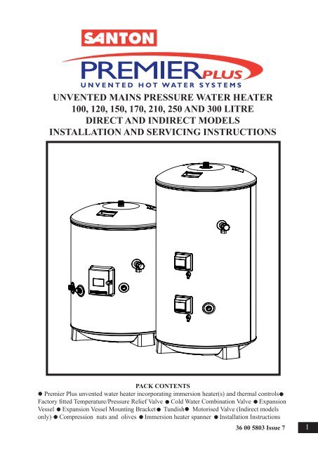
UNVENTED MAINS PRESSURE WATER HEATER<br />
100, 120, 150, 170, 210, 250 AND 300 LITRE<br />
DIRECT AND INDIRECT MODELS<br />
INSTALLATION AND SERVICING INSTRUCTIONS<br />
PACK CONTENTS<br />
<strong>Premier</strong> <strong>Plus</strong> unvented water heater incorporating immersion heater(s) and thermal controls<br />
Factory fitted Temperature/Pressure Relief Valve Cold <strong>Water</strong> Combination Valve Expansion<br />
Vessel Expansion Vessel Mounting Bracket Tundish Motorised Valve (Indirect models<br />
only) Compression nuts and olives Immersion heater spanner <strong>Installation</strong> Instructions<br />
36 00 5803 Issue 7<br />
1
SANTON PREMIER PLUS INSTALLATION AND SERVICING INSTRUCTIONS.<br />
PLEASE LEAVE THIS MANUAL WITH THE UNIT FOR FUTURE REFERENCE.<br />
CONTENTS<br />
SECTION CONTENT PAGE<br />
1 INTRODUCTION . . . . . . . 2<br />
2 GENERAL REQUIREMENTS . . . . . . 3<br />
3 INSTALLATION - GENERAL . . . . . . 4<br />
4 INSTALLATION - DIRECT UNITS . . . . . . 9<br />
5 INSTALLATION – INDIRECT UNITS . . . . . 9<br />
6 COMMISSIONING . . . . . . . 11<br />
7 MAINTENANCE . . . . . . . 12<br />
8 FAULT FINDING AND SERVICING . . . . . 13<br />
9 USER INSTRUCTIONS . . . . . . 15<br />
10 GUARANTEE . . . . . . . . 16<br />
11 SPARES STOCKISTS . . . . . . . 16<br />
1.0 INTRODUCTION<br />
The <strong>Santon</strong> <strong>Premier</strong> <strong>Plus</strong> is a purpose designed<br />
unvented water heater. The unit has a stainless steel<br />
inner vessel which ensures an excellent standard of<br />
corrosion resistance. The outer casing is a combination<br />
of resilient thermoplastic mouldings and plastic<br />
coated corrosion proofed steel sheet. All <strong>Premier</strong>s<br />
are insulated with CFC free polyurethane foam to<br />
meet the latest European heat loss requirements (see<br />
Table 3).<br />
The unit is supplied complete with all the necessary<br />
safety and control devices needed to allow connection<br />
to the cold water mains. All these components<br />
are pre-adjusted.<br />
This appliance complies with the requirements of<br />
the CE marking directive and is WRAS approved to<br />
show compliance with Building Regulations (Section<br />
G3).<br />
The following instructions are offered as a guide to<br />
installation which must be carried out by a competent<br />
plumbing and electrical installer in accordance with<br />
Building Regulation G3, The Building Standards<br />
(Scotland) Regulations 1990, or The Building Regula-<br />
NOTE: Prior to installation the unit should be stored<br />
in an upright position in an area free from excessive<br />
damp or humidity.<br />
TABLE 1: OPERATIONAL SUMMARY<br />
Maximum water supply pressure to PRV 16.0 bar<br />
Operating pressure of unit<br />
3.5 bar<br />
Expansion vessel charge pressure 3.5 bar<br />
Expansion valve setting<br />
6.0 bar<br />
Nominal storage capacity of units (see Section 2 Table 2)<br />
Max. primary working pressure<br />
3.0 bar (indirects only)<br />
Opening temperature of T&P Relief Valve 90deg C<br />
Opening pressure of T&P Relief Valve 10 bar<br />
2<br />
IMPORTANT: PLEASE READ ALL THESE INSTRUCTIONS BEFORE<br />
COMMENCING INSTALLATION
2.0 GENERAL REQUIREMENTS<br />
2.1 COMPONENTS SUPPLIED<br />
1. <strong>Premier</strong> <strong>Plus</strong> unvented water heater incorporating<br />
immersion heater(s) and thermal controls<br />
2. Factory fitted Temperature/Pressure Relief Valve<br />
3. Cold <strong>Water</strong> Combination Valve.<br />
4. Expansion Vessel and mounting bracket.<br />
5. Tundish.<br />
6. Motorized Valve (Indirect models only).<br />
7. Compression nuts and olives<br />
8. Immersion heater key spanner<br />
2.2 SITING THE UNIT<br />
The <strong>Santon</strong> <strong>Premier</strong> <strong>Plus</strong> must be installed vertically.<br />
Although location is not critical, the following points<br />
should be considered:<br />
• The <strong>Santon</strong> <strong>Premier</strong> <strong>Plus</strong> should be sited to ensure<br />
minimum dead leg distances, particularly to the point<br />
of most frequent use.<br />
• Avoid siting where extreme cold temperatures<br />
will be experienced. All exposed pipework should be<br />
insulated.<br />
• The discharge pipework from the safety valves<br />
must have minimum fall of 1:200 from the unit and<br />
terminate in a safe and visible position.<br />
• Access to associated controls and immersion<br />
heaters should be possible to allow for periodic servicing<br />
and maintenance.<br />
• Ensure that the base chosen for the <strong>Santon</strong><br />
<strong>Premier</strong> <strong>Plus</strong> is level and capable of permanently<br />
supporting the weight when full of water (see Table<br />
2).<br />
Table 2: Unit weights<br />
Type<br />
Model<br />
reference<br />
Nominal<br />
capacity<br />
(litres)<br />
W eight of<br />
unit full<br />
(kg)<br />
DIRECT PP100E 100 123<br />
PP120E 120 145<br />
PP150E 150 178<br />
PP170E 170 199<br />
PP210E 210 246<br />
PP250E 250 295<br />
PP300E 300 355<br />
INDIRECT PP100B 100 125<br />
PP120B 120 147<br />
PP150B 150 181<br />
PP170B 170 203<br />
PP210B 210 251<br />
PP250B 250 300<br />
PP300B 300 360<br />
2.3 WATER SUPPLY<br />
Bear in mind that the mains water supply to the<br />
property will be supplying both the hot and cold water<br />
requirements simultaneously. It is recommended<br />
that the maximum water demand is assessed and the<br />
water supply checked to ensure this demand can be<br />
satisfactorily met.<br />
NOTE: A high mains water pressure will not always<br />
guarantee high flowrates.<br />
Wherever possible the mains supply pipe should be<br />
22mm. We suggest the minimum supply requirements<br />
should be 1.5 bar pressure and 20 litres per minute<br />
flowrate. However, at these values outlet flowrates<br />
may be poor if several outlets are used simultaneously.<br />
The higher the available pressure and flowrate<br />
the better the system performance.<br />
The <strong>Santon</strong> <strong>Premier</strong> <strong>Plus</strong> has an operating pressure of<br />
3.5 bar that is controlled by the Cold <strong>Water</strong> Combination<br />
Valve. The Cold <strong>Water</strong> Combination Valve can be<br />
connected to a maximum mains pressure of 16 bar.<br />
2.4 OUTLET/TERMINAL FITTINGS (TAPS, ETC.)<br />
The <strong>Santon</strong> <strong>Premier</strong> <strong>Plus</strong> can be used with most<br />
types of terminal fittings. It is advantageous in many<br />
mixer showers to have balanced hot and cold water<br />
supplies. In these instances a balanced pressure cold<br />
water connection should be placed between the Cold<br />
<strong>Water</strong> Combination Valve and the <strong>Premier</strong> <strong>Plus</strong> water<br />
heater. Outlets situated higher than the <strong>Santon</strong> <strong>Premier</strong><br />
<strong>Plus</strong> will give outlet pressures lower than that at the<br />
heater, a 10m height difference will result in a 1 bar<br />
pressure reduction at the outlet.<br />
2.5 LIMITATIONS<br />
The <strong>Premier</strong> <strong>Plus</strong> unvented water heater should not be<br />
used in association with any of the following:<br />
• Solid fuel boilers or any other boiler in which the<br />
energy input is not under effective thermostatic control<br />
unless additional and appropriate safety measures are<br />
installed.<br />
• Ascending spray type bidets or any other class 1<br />
back syphonage risk requiring that a type A air gap<br />
be employed.<br />
• Steam heating plants unless additional and appropriate<br />
safety devices are installed.<br />
• Situations where maintenance is likely to be<br />
neglected or safety devices tampered with.<br />
• <strong>Water</strong> supplies that have either inadequate pressure<br />
or where the supply may be intermittent.<br />
• Situations where it is not possible to safely pipe<br />
away any discharge from the safety valves.<br />
• In areas where the water consistently contains a<br />
high proportion of solids, e.g. suspended matter that<br />
could block the strainer, unless adequate filtration can<br />
be ensured.<br />
Table 3: Standing heat losses<br />
Nominal Standing Heat Loss<br />
capacity per day per year<br />
(litres) (kW h/24h) (kW h/365d)<br />
100 1.14 416.1<br />
120 1.25 456.3<br />
150 1.45 529.3<br />
170 1.63 595.0<br />
210 1.91 697.2<br />
250 2.22 810.3<br />
300 2.52 919.8<br />
Based on an ambient air temperature of 20 o C and a<br />
stored water temperature of 65 o C<br />
3
3.0 INSTALLATION – GENERAL<br />
(FIGS 3 & 5)<br />
3.1 PIPE FITTINGS<br />
All pipe fittings are made via 22mm compression<br />
fittings directly to the unit. The fittings are threaded<br />
3/4”BSP male parallel should threaded pipe connections<br />
be required.<br />
3.2 COLD FEED<br />
A 22mm cold water supply is recommended however,<br />
if a 15mm (1/2”) supply exists which provides sufficient<br />
flow this may be used (although more flow<br />
noise may be experienced).<br />
A stopcock or servicing valve should be incorporated<br />
into the cold water supply to enable the <strong>Santon</strong> <strong>Premier</strong><br />
<strong>Plus</strong> and its associated controls to be isolated<br />
and serviced.<br />
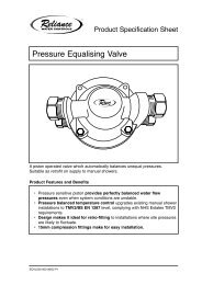
3.3 COLD WATER COMBINATION VALVE (FIG 1)<br />
The Cold <strong>Water</strong> Combination Valve can be connected<br />
anywhere on the cold water mains supply prior to the<br />
Expansion Vessel (see Fig. 5). The Cold <strong>Water</strong> Combination<br />
Valve is installed as a complete one-piece<br />
unit. The valve incorporates the Pressure Reducer,<br />
Strainer, Expansion Valve and Check Valve. Ensure<br />
that the valve is installed with the direction of flow<br />
arrows pointing in the right direction. No other valves<br />
should be placed between the Cold <strong>Water</strong> Combination<br />
Valve and the <strong>Premier</strong> <strong>Plus</strong> unit. The Expansion Valve<br />
connection must not be used for any other purpose.<br />
EXPANSION VALVE<br />
EXPANSION VALVE<br />
OUTLET (15mm)<br />
3.5 EXPANSION VESSEL<br />
The Expansion Vessel accommodates expansion that<br />
results from heating the water inside the unit. The unit<br />
is pre-charged at 3.5 bar. The Expansion Vessel must<br />
be connected between the Cold <strong>Water</strong> Combination<br />
Valve and the <strong>Santon</strong> <strong>Premier</strong> <strong>Plus</strong> (see Fig. 5). The<br />
location of the Expansion Vessel should allow access<br />
to recharge the pressure as and when necessary, this<br />
can be done using a normal car foot pump. It is recommended<br />
that the Expansion Vessel is adequately supported.<br />
An Expansion Vessel wall mounting bracket<br />
is supplied for this purpose<br />
3.6 SECONDARY CIRCULATION<br />
If secondary circulation is required it is recommended<br />
that it be connected to the <strong>Premier</strong> as shown in Fig.<br />
2 via a swept tee joint into the cold feed to the unit.<br />
A Swept Tee joint is available as an accessory order<br />
code no. 94 970 033.<br />
The secondary return pipe should be in 15mm pipe<br />
and incorporate a check valve to prevent backflow. A<br />
suitable WRAS approved bronze circulation pump<br />
will be required. On large systems, due to the increase<br />
in system water content, it may be necessary to fit an<br />
additional expansion vessel to the secondary circuit.<br />
this should be done if the capacity of the secondary<br />
circuit exceeds 10 litres.<br />
Pipe capacity (copper)<br />
15mm o/d = 0.13 l/m (10 litres = 77m)<br />
22mm o/d = 0.38 l/m (10 litres = 26m)<br />
28mm o/d = 0.55 l/m (10 litres = 18m)<br />
Secondary circulation is NOT recommended for direct<br />
electric units being used on Off Peak electricity<br />
tariffs.<br />
COLD MAINS<br />
CONNECTION<br />
(22mm)<br />
PRESSURE<br />
REDUCING<br />
VALVE<br />
HOUSING<br />
PRESSURE<br />
REDUCING<br />
VALVE<br />
CARTRIDGE (3.5 bar)<br />
OUTLET<br />
CONNECTION<br />
(22mm)<br />
FIG. 1 Cold <strong>Water</strong> Combination Valve<br />
3.4 DRAIN TAP<br />
A suitable draining tap should be installed in the cold<br />
water supply to the <strong>Premier</strong> <strong>Plus</strong> unit between the<br />
Cold <strong>Water</strong> Combination Valve and the heater at as<br />
low a level as possible. It is recommended that the<br />
outlet point of the drain pipework be at least 1 metre<br />
below the level of the heater (this can be achieved by<br />
attaching a hose to the drain tap outlet spigot).<br />
COLD<br />
INLET <br />
CONNECTION<br />
SWEPT<br />
TEE<br />
COLD<br />
SUPPLY<br />
CHECK<br />
VALVE<br />
SECONDARY<br />
CIRCULATION<br />
PUMP<br />
SECONDARY<br />
RETURN<br />
FIG. 2 Secondary circulation connection<br />
3.7 OUTLET<br />
The hot water outlet is a 22mm compression fitting<br />
located at the top of the cylinder. Hot water distribution<br />
pipework should be 22mm pipe with short runs<br />
of 15mm pipe to terminal fittings such as sinks and<br />
basins. Pipe sizes may vary due to system design.<br />
4
NOMINAL<br />
CAPACITY<br />
(litres)<br />
TYPE DIMENSIONS (mm) COIL<br />
E = DIRECT<br />
SURFACE<br />
RATING<br />
B = INDIRECT<br />
AREA<br />
(kW)<br />
A B C D (sq.m)<br />
100 E<br />
306 493 784<br />
100 B 315 354 493 784 0.43 11.8 18<br />
120 E<br />
306 615 906<br />
120 B 315 354 615 906 0.43 12.5 22<br />
150 E<br />
306 800 1090<br />
150 B 315 354 800 1090 0.55 16.4 21<br />
170 E<br />
306 925 1216<br />
170 B 315 354 925 1216 0.61 16.0 24<br />
210 E<br />
306 1184 1474<br />
210 B 315 354 1184 1474 0.68 18.3 26<br />
250 E<br />
306 1391 1726<br />
250 B 315 354 1391 1726 0.79 20.0 27<br />
300 E<br />
306 1715 2040<br />
RECOVERY<br />
(mins)<br />
300 B 315 354 1715 2040 0.79 20.0 33<br />
NOTES:<br />
1. Recovery time based on heating 70% of capacity through 45 deg. C<br />
2. Direct heating times assume use of lower element only<br />
FIG. 3 General Dimensions<br />
HEATING<br />
TIME<br />
DIRECT<br />
(mins)<br />
99<br />
121<br />
152<br />
173<br />
215<br />
257<br />
310<br />
M ode l<br />
Heating tim e<br />
15 to 65de g. C<br />
70% Re cove ry<br />
tim e<br />
Note s<br />
P P 100E 2hours 08m ins 1hour 17m ins<br />
3kW input<br />
P P 150E 1hour 33m ins 1hour 08m ins 6kW input (using both im m ersion heaters)<br />
P P 210E 2hours 21m ins 1hour 51m ins 6kW input (using both im m ersion heaters)<br />
P P 100B 21m ins 15m ins Indirectly heated. P rim ary flow 82deg. C at 15l/m in<br />
P P 150B 24m ins 20m ins Indirectly heated. P rim ary flow 82deg. C at 15l/m in<br />
P P 210B 32m ins 29m ins Indirectly heated. P rim ary flow 82deg. C at 15l/m in<br />
Test results obtained by WRc-NSF in accordance with Test Criteria 1-50-220 and 1-50-222<br />
5
6<br />
3.8 DISCHARGE PIPEWORK<br />
It is a requirement of Building Regulation G3 that any<br />
discharge from an unvented system is conveyed to<br />
where it is visible, but will not cause danger to persons<br />
in or about the building. The tundish and discharge<br />
pipes should be fitted in accordance with the requirements<br />
and guidance notes of Building Regulation G3.<br />
The G3 Requirements and Guidance section 3.9 are<br />
reproduced in the following sections.<br />
Information Sheet No. 33 available from the British<br />
Board of Agrement gives further advice on discharge<br />
pipe installation. For discharge pipe arrangements not<br />
covered by G3 Guidance or BBA Info Sheet No.33<br />
advice should be sought from either your local Building<br />
Control Officer or <strong>Santon</strong>.<br />
G3 REQUIREMENT<br />
“...there shall be precautions...to ensure that the<br />
hot water discharged from safety devices is safely<br />
conveyed to where it is visible but will not cause<br />
danger to persons in or about the building.”<br />
G3 GUIDANCE SECTION 3.9<br />
The discharge pipe (D1) from the vessel up to and<br />
including the tundish is generally supplied by the<br />
manufacturer of the hot water storage system. Where<br />
otherwise, the installation should include the discharge<br />
pipe(s) (D1) from the safety device(s). In either case<br />
the tundish should be vertical, located in the same<br />
space as the unvented hot water storage system and<br />
be fitted as close as possible and within 500mm of the<br />
safety device e.g. the temperature relief valve.<br />
The discharge pipe (D2) from the tundish should<br />
terminate in a safe place where there is no risk to<br />
persons in the vicinity of the discharge, preferably<br />
be of metal and:<br />
a. be at least one pipe size larger than the nominal<br />
outlet size of the safety device unless its total equivalent<br />
hydraulic resistance exceeds that of a straight<br />
pipe 9m long i.e. discharge pipes between 9m and<br />
18m equivalent resistance length should be at least<br />
two sizes larger than the nominal outlet size of the<br />
safety device, between 18 and 27m at least 3 sizes<br />
larger , and so on. Bends must be taken into account<br />
in calculating the flow resistance. Refer to Diagram<br />
1, Table 1 and the worked example.<br />
An alternative approach for sizing discharge pipes<br />
would be to follow BS 6700:1987 Specification<br />
for design installation, testing and maintenance of<br />
services supplying water for domestic use within<br />
buildings and their curtilages, Appendix E, section<br />
E2 and table 21.<br />
b. have a vertical section of pipe at least 300mm<br />
long, below the tundish before any elbows or bends<br />
in the pipework.<br />
c. be installed with a continuous fall.<br />
d. have discharges visible at both the tundish and the<br />
final point of discharge but where this is not possible<br />
or is practically difficult there should be clear visibility<br />
at one or other of these locations. Examples of<br />
acceptable discharge arrangements are:<br />
i. ideally below a fixed grating and above the water<br />
seal in a trapped gully.<br />
ii. downward discharges at low level; i.e. up to<br />
100mm above external surfaces such as car parks, hard<br />
standings, grassed areas etc. are acceptable providing<br />
that where children may play or otherwise come into<br />
contact with discharges a wire cage or similar guard<br />
is positioned to prevent contact, whilst maintaining<br />
visibility.<br />
iii. discharges at high level; e.g. into a metal hopper<br />
and metal down pipe with the end of the discharge pipe<br />
clearly visible (tundish visible or not) or onto a roof<br />
capable of withstanding high temperature discharges<br />
of water and 3m from any plastics guttering system<br />
that would collect such discharges (tundish visible).<br />
iv. where a single pipe serves a number of discharges,<br />
such as in blocks of flats, the number served should<br />
be limited to not more than 6 systems so that any<br />
instalation discharging can be traced reasonably easily.<br />
The single common discharge pipe should be at<br />
least one pipe size larger than the largest individual<br />
discharge pipe (D2) to be connected. If unvented hot<br />
water storage systems are installed where discharges<br />
from safety devices may not be apparent i.e. in dwellings<br />
occupied by blind, infirm or disabled people,<br />
consideration should be given to the installation of an<br />
electronically operated device to warn when discharge<br />
takes place.<br />
Note: The discharge will consist of scalding water and<br />
steam. Asphalt, roofing felt and non-metallic rainwater<br />
goods may be damaged by such discharges.<br />
Worked example of discharge pipe sizing<br />
The example below is for a G1/2 temperature relief<br />
valve with a discharge pipe (D2) having 4 No. elbows<br />
and length of 7m from the tundish to the point of discharge.<br />
From Table 4:<br />
Maximum resistance allowed for a straight length of<br />
22mm copper discharge pipe (D2) from a G1/2 temperature<br />
relief valve is 9.0m.<br />
Subtract the resistance for 4 No. 22mm elbows at 0.8m<br />
each = 3.2m<br />
Therefore the permitted length equates to: 5.8m<br />
5.8m is less than the actual length of 7m therefore calculate<br />
the next largest size.<br />
Maximum resistance allowed for a straight length of<br />
28mm pipe (D2) from a G1/2 temperature relief valves<br />
equates to 18m.<br />
Subtract the resistance of 4 No. 28mm elbows at 1.0m<br />
each = 4.0m<br />
Therefore the maximum permitted length equates to:<br />
14m<br />
As the actual length is 7m, a 28mm (D2) copper pipe<br />
will be satisfactory.
3.9 WARNINGS<br />
• Under no circumstances should the factory fitted<br />
Temperature/Pressure Relief Valve be removed other<br />
than by authorised <strong>Santon</strong> personnel. To do so will<br />
invalidate any guarantee or claim.<br />
• The Cold <strong>Water</strong> Combination Valve must be fitted<br />
to the mains water supply to the <strong>Premier</strong> <strong>Plus</strong> unit.<br />
• No control or safety valves should be tampered<br />
with.<br />
• The discharge pipe should not be blocked or used<br />
for any other purpose.<br />
• The tundish should not be located adjacent to any<br />
electrical components.<br />
Valve outlet size<br />
Minimum size of<br />
discharge pipe<br />
D1<br />
G1/2 15mm<br />
G3/4 22mm<br />
G1<br />
28mm<br />
Minimum size of<br />
discharge pipe<br />
D2 from tundish<br />
22mm<br />
28mm<br />
35mm<br />
28mm<br />
35mm<br />
42mm<br />
35mm<br />
42mm<br />
54mm<br />
Maximum<br />
resistance<br />
allow ed,<br />
expressed as a<br />
length of straight<br />
pipe (I.e. no<br />
elbow s or bends)<br />
up to 9m<br />
up to 18m<br />
up to 27m<br />
up to 9m<br />
up to 18m<br />
up to 27m<br />
up to 9m<br />
up to 18m<br />
up to 27m<br />
Resistance<br />
created by each<br />
elbow or bend<br />
0.8m<br />
1.0m<br />
1.4m<br />
1.0m<br />
1.4m<br />
1.7m<br />
1.4m<br />
1.7m<br />
2.3m<br />
Table 4 Sizing of copper discharge pipe (D2) for common temperature relief valve outlet<br />
Safety device<br />
(e.g. Temperature<br />
relief valve)<br />
Metal discharge pipe (D1) from<br />
Temperature relief valve to tundish<br />
500mm maximum<br />
Tundish<br />
300mm<br />
minimum<br />
Discharge pipe (D2) from tundish,<br />
with continuous fall. See Building<br />
Regulation G3 section 3.9d i-iv,<br />
Table 4 and worked example<br />
Discharge below<br />
fixed grating<br />
(Building Regulation<br />
G3 section 3.9d gives<br />
alternative points<br />
of discharge)<br />
Fixed grating<br />
Trapped<br />
gully<br />
FIG. 4 Typical discharge pipe arrangement (extract from Building Regulation G3 Guidance<br />
section 3.9)<br />
7
TO HOT<br />
OUTLETS<br />
BOOST ELEMENT /<br />
CONTROL HOUSING<br />
(PP120E TO PP300E<br />
MODELS ONLY)<br />
ELEMENT /<br />
CONTROLS<br />
HOUSING<br />
T&P RELIEF<br />
VALVE<br />
EXPANSION<br />
VESSEL<br />
BALANCED<br />
COLD WATER<br />
CONNECTION<br />
(IF REQUIRED)<br />
COLD WATER<br />
COMBINATION<br />
VALVE<br />
MAINS<br />
WATER<br />
SUPPLY<br />
ISOLATING<br />
VALVE (NOT<br />
SUPPLIED)<br />
PRIMARY<br />
RETURN<br />
PRIMARY<br />
FLOW<br />
NOTE: PRIMARY HEATING COIL<br />
FITTED ON PP100B TO PP300B<br />
MODELS ONLY<br />
DRAIN COCK<br />
(NOT SUPPLIED)<br />
INLET<br />
SECONDARY<br />
RETURN<br />
TAPPING (IF<br />
REQUIRED)<br />
TUNDISH<br />
DISCHARGE<br />
PIPE<br />
FIG. 5 Typical installation - schematic<br />
DIRECT MODELS<br />
INDIRECT MODELS<br />
B<br />
EARTH<br />
CONNECTION<br />
INDIRECT THERMAL CUT-OUT<br />
INDIRECT THERMOSTAT<br />
BROWN<br />
A<br />
BLUE<br />
THERMOSTAT<br />
GREEN/YELLOW<br />
1 2 1 2 3<br />
FUSED (13A) DOUBLE<br />
POLE ISOLATING<br />
SWITCH<br />
GREEN / YELLOW<br />
DIRECT THERMOSTAT<br />
B<br />
BLUE<br />
1 2<br />
3<br />
GREEN/<br />
YELLOW<br />
A<br />
1.5mm 2 3 CORE<br />
HOFR SHEATHED<br />
CABLE<br />
Note: On models fitted with two or three elements each element must be<br />
wired individually in accordance with the diagram above.<br />
BROWN<br />
13 AMP MAINS<br />
SUPPLY. 1.5mm 2<br />
MIN. CABLE SIZE<br />
TO INDIRECT SYSTEM<br />
CONTROLS JUNCTION<br />
BOX - SEE FIGS. 7/8<br />
FIG. 6 Electrical Connections (Schematic)<br />
8
4.0 INSTALLATION - DIRECT<br />
UNITS<br />
4.1 PLUMBING CONNECTIONS<br />
Direct units require the following pipework connections.<br />
• Cold water supply to and from inlet controls.<br />
• Outlet to hot water draw off points.<br />
• Discharge pipework from valve outlets to<br />
tundish.<br />
4.2 ELECTRICAL SUPPLY (FIG. 6)<br />
100 litre direct <strong>Premier</strong> <strong>Plus</strong> units are fitted with one<br />
3kW immersion heater, all other direct models are<br />
fitted with two 3kW immersion heaters as standard.<br />
It is recommended that these should be wired via a<br />
suitable controller to BSEN 60730. The <strong>Premier</strong> <strong>Plus</strong><br />
MUST be earthed. The 250 and 300 litre units have<br />
an additional boss which has a blanking plug fitted.<br />
An additional immersion heater can be fitted in place<br />
of the blanking plug where a higher electrical input<br />
is required for faster recovery times, order Part No.<br />
95 970 510 if required.<br />
All wiring to the unit must be installed in accordance<br />
with the latest IEE Wiring Regulations and the circuit<br />
must be protected by a suitable fuse and double pole<br />
isolating switch with a contact separation of at least<br />
3mm in both poles. The Live and Neutral connections<br />
are made directly onto the combined thermostat and<br />
thermal cut-out located under the terminal cover(s)<br />
mounted on the side of the unit. The Earth connection<br />
should be made to the earth connection located to<br />
the side of the immersion heater boss(es). The supply<br />
cable must be routed through the cable gland located<br />
on the unit casing beneath the terminal housing.<br />
DO NOT operate the immersion heaters until the <strong>Santon</strong><br />
<strong>Premier</strong> <strong>Plus</strong> has been filled with water.<br />
4.3 SAFETY<br />
DISCONNECT FROM THE MAINS SUPPLY<br />
BEFORE REMOVING ANY COVERS.<br />
Never attempt to replace the immersion heater(s)<br />
other than with the recommended <strong>Santon</strong> immersion<br />
heater(s).<br />
DO NOT bypass the thermal cut-out(s)<br />
in any circumstances. Ensure the two male<br />
spade terminations on the underside of the combined<br />
thermostat and thermal cut-out are pushed firmly onto<br />
the corresponding terminations on the element plate<br />
assembly.<br />
In case of difficulty contact <strong>Santon</strong> service, tel:<br />
5.0 INSTALLATION - INDIRECT<br />
UNITS<br />
5.1 PLUMBING CONNECTIONS<br />
Indirect units require the following pipework connections.<br />
• Cold water supply to and from inlet controls.<br />
• Outlet to hot water draw off points.<br />
• Discharge pipework from valve outlets to<br />
tundish<br />
• Connection to the primary circuit.<br />
Primary connections are 22mm compression. However,<br />
3/4”BSP parallel threaded fittings can be fitted<br />
to the primary coil connections if required.<br />
5.2 ELECTRICAL SUPPLY (FIG. 6)<br />
All Indirect units are fitted with a 3kW immersion<br />
heater and a combined thermostat and thermal cut-out<br />
to control the indirect heating source. The <strong>Premier</strong><br />
<strong>Plus</strong> MUST be earthed.<br />
All wiring to the unit must be installed in accordance<br />
with the latest IEE Wiring Regulations and the supply<br />
circuits must be protected by a suitable fuse and double<br />
pole isolating switch with a contact separation of at<br />
least 3mm in both poles. All connections are made to<br />
the terminal block located under the terminal cover<br />
mounted on the side of the unit. The supply cable(s)<br />
must be routed through the cable grip(s) in the terminal<br />
housing.<br />
DISCONNECT FROM MAINS SUPPLY BE-<br />
FORE REMOVING ANY COVERS. DO NOT<br />
bypass the thermal cut-outs in any<br />
circumstances. Ensure the thermostat and<br />
thermal cut-out sensing bulbs are pushed fully into<br />
the pockets on the element plate assembly.<br />
5.3 BOILER SELECTION<br />
The boiler should have a control thermostat and non<br />
self-resetting thermal cut-out and be compatible with<br />
unvented storage water heaters.<br />
Where use of a boiler without a thermal cut-out is<br />
unavoidable a “low head” open vented primary circuit<br />
should be used. The Feed and Expansion cistern head<br />
above the <strong>Premier</strong> <strong>Plus</strong> should not exceed 2.5m.<br />
5.4 PRIMARY CIRCUIT CONTROL<br />
The 2 port motorised valve supplied with the <strong>Premier</strong><br />
<strong>Plus</strong> indirect units MUST be fitted to the primary flow<br />
to the <strong>Premier</strong> <strong>Plus</strong> heat exchanger and wired in series<br />
with the indirect thermostat and thermal cut-out fitted<br />
to the unit.<br />
Primary circulation to the <strong>Premier</strong> <strong>Plus</strong> heat exchanger<br />
must be pumped, gravity circulation WILL NOT<br />
WORK.<br />
5.5 SPACE AND HEATING SYSTEMS CONTROLS<br />
The controls provided with the <strong>Santon</strong> <strong>Premier</strong> <strong>Plus</strong><br />
will ensure the safe operation of the unit within a<br />
central heating system. Other controls will be necessary<br />
to control the space heating requirements and<br />
times that the system is required to function (see<br />
Fig. 7). The <strong>Santon</strong> <strong>Premier</strong> <strong>Plus</strong> is compatible with<br />
most heating controls, examples of electrical circuits<br />
are shown in Figs. 7 and 8. However, other systems<br />
may be suitable, refer to the controls manufacturers’<br />
instructions, supplied with the controls selected, for<br />
alternative system wiring schemes.<br />
9
Control terminal numbering may<br />
differ from those shown. Refer to<br />
instructions with controls<br />
selected<br />
ZONE VALVE (HTG)<br />
PREMIER PLUS<br />
TERMINAL BLOCK<br />
ROOM STAT<br />
G Br Bl O GY 1 3 2<br />
1<br />
2 3<br />
3<br />
ZONE VALVE(DHW)<br />
(SUPPLIED)<br />
G Br Bl O GY<br />
1 2 3 2<br />
1 2 3<br />
A DOUBLE POLE ISOLATING<br />
SWITCH MUST BE INSTALLED<br />
IN THE MAINS SUPPLY.<br />
ALL EARTH CONNECTIONS<br />
BE CONNECTED BACK TO<br />
THE MAINS EARTH SUPPLY<br />
L<br />
(SUPPLY)<br />
N<br />
1 2 3 4 5 6 7 8 9 10<br />
1 2 3 4 5 6 7 8 9 10<br />
JUNCTION BOX<br />
1 2 3<br />
L N<br />
HTG DHW<br />
ON ON<br />
PROGRAMMER<br />
2 3<br />
L N<br />
BOILER<br />
2<br />
L<br />
N<br />
3<br />
PUMP<br />
FIG. 7 Schematic wiring diagram - Basic 2 x 2 port valve system<br />
Control terminal numbering may<br />
differ from those shown. Refer to<br />
instructions with controls<br />
selected<br />
ZONE VALVE (HTG)<br />
G W Bl O GY<br />
PREMIER PLUS<br />
TERMINAL BLOCK<br />
1<br />
2 3<br />
3<br />
ZONE VALVE(DHW)<br />
(SUPPLIED)<br />
G Br Bl O GY<br />
2<br />
3 1 2 3<br />
A DOUBLE POLE ISOLATING<br />
SWITCH MUST BE INSTALLED<br />
IN THE MAINS SUPPLY.<br />
ALL EARTH CONNECTIONS<br />
BE CONNECTED BACK TO<br />
THE MAINS EARTH SUPPLY<br />
L<br />
(SUPPLY)<br />
N<br />
1 2 3 4 5 6 7 8 9 10<br />
1 2 3 4 5 6 7 8 9 10<br />
JUNCTION BOX<br />
1 2 3<br />
L N<br />
HTG<br />
ON<br />
DHW<br />
ON<br />
PROGRAMMER<br />
DHW<br />
OFF<br />
2<br />
1 3 2<br />
L<br />
2 3<br />
N<br />
2<br />
L<br />
N<br />
3<br />
PUMP<br />
ROOM STAT<br />
BOILER<br />
FIG. 8 Schematic wiring diagram - 3 port mid position valve system. N.B. Must be used in<br />
conjunction with 2 port zone valve suuplied<br />
10
6.0 COMMISSIONING<br />
6.1 FILLING THE UNIT WITH WATER<br />
• Check Expansion Vessel pre-charge pressure. The<br />
vessel is supplied pre-charged to 3.5 bar to match the<br />
control pressure of the Pressure Reducing Valve. The<br />
pre-charge pressure is checked using a car tyre gauge<br />
by unscrewing the plastic cap opposite the water connection.<br />
• Check all connections for tightness including the<br />
immersion heater(s). An immersion heater key spanner<br />
is supplied for this purpose.<br />
• Ensure the drain cock is CLOSED.<br />
• Open a hot tap furthest from the <strong>Santon</strong> <strong>Premier</strong><br />
<strong>Plus</strong>.<br />
• Open the mains stop cock to fill the unit. When<br />
water flows from the tap, allow to run for a few minutes<br />
to thoroughly flush through any residue, dirt or<br />
swarf, then close the tap.<br />
• Open successive hot taps to purge the system of<br />
air.<br />
6.2 SYSTEM CHECKS<br />
• Check all water connections for leaks and rectify<br />
as necessary.<br />
• Remove the Pressure Reducing Valve headwork<br />
to access the strainer mesh, clean and re-fit.<br />
• Manually open, for a few seconds, each relief<br />
valve in turn, checking that water is discharged and<br />
runs freely through the tundish and out at the discharge<br />
point.<br />
• Ensure that the valve(s) reseat satisfactorily.<br />
6.3 DIRECT UNITS<br />
Switch on electrical supply to the immersion heater(s)<br />
and allow the <strong>Premier</strong> <strong>Plus</strong> to heat up to normal working<br />
temperature (60ºC recommended, approximately<br />
graduation 4 on the thermostat). If necessary the<br />
temperature can be adjusted by inserting a flat bladed<br />
screwdriver in the adjustment knob on top of the immersion<br />
heater thermostat and rotating. The adjustment<br />
range 1 to 5 represents a temperature range of<br />
10 o to 70 o C. Check the operation of thermostat(s) and<br />
that no water has issued from the Expansion Relief<br />
Valve or Temperature/Pressure Relief Valve during<br />
the heating cycle.<br />
6.4 INDIRECT UNITS<br />
Fill the indirect (primary) circuit following the boiler<br />
manufacturer’s commissioning instructions. To ensure<br />
the <strong>Premier</strong> <strong>Plus</strong> primary heat exchanger is filled, the<br />
2 port motorised valve (supplied) should be manually<br />
opened by moving the lever on the motor housing to<br />
the FLUSHING ONLY setting. When the primary<br />
circuit is full return the lever to the NORMAL USE<br />
position. Switch on the boiler, ensure the programmer<br />
is set to Domestic Hot <strong>Water</strong> and allow the <strong>Premier</strong><br />
<strong>Plus</strong> to heat up to a normal working temperature<br />
(60 o C recommended, approximately graduation 4<br />
on the thermostat). If necessary the temperature can<br />
be adjusted by inserting a flat bladed screwdriver in<br />
the adjustment knob (located on top of the thermostat<br />
mounting bracket - see Fig.9) and rotating. The<br />
minimum thermostat setting is 10 o C. The adjustment<br />
range 1 to 5 represents a temperature range of 30 o to<br />
70 o C. Check the operation of the indirect thermostat<br />
and 2 port motorised valve and that no water has issued<br />
from the Expansion Relief Valve or Temperature/<br />
PressureRelief Valve during the heating cycle.<br />
INDIRECT<br />
THERMAL<br />
CUT-OUT<br />
CABLE CLAMPS<br />
INDIRECT THERMAL<br />
CUT-OUT RESET<br />
BUTTON<br />
THERMOSTAT<br />
ADJUSTMENT<br />
INDIRECT<br />
THERMOSTAT<br />
TERMINAL BLOCK<br />
NOTE:<br />
THE HOUSING COVER AND ELEMENT ASSEMBLY<br />
HAVE BEEN REMOVED FROM THIS VIEW FOR<br />
CLARITY<br />
FIG. 9 Indirect thermostat and thermal cutout<br />
6.5 BENCHMARK TM LOG BOOK<br />
On completion of the installation and commissioning<br />
of the <strong>Premier</strong> <strong>Plus</strong> the Benchmark TM “<strong>Installation</strong>,<br />
Commissioning and Service Record Log Book”<br />
should be completed and signed off by the competent<br />
installer or commissioning engineer in the relevant<br />
sections.<br />
The various system features, location of system controls,<br />
user instructions and what to do in the event of<br />
a system failure should be explained to the customer.<br />
The customer should then countersign the Benchmark<br />
TM log book to accept completion.<br />
The log book should be left with the customer along<br />
with these instructions. The log book includes sections<br />
that should be filled out when any subsequent service<br />
or maintenance operation is carried out on the <strong>Premier</strong><br />
<strong>Plus</strong> system.<br />
11
12<br />
7.0 MAINTENANCE<br />
7.1 MAINTENANCE REQUIREMENTS<br />
Unvented hot water systems have a continuing maintenance<br />
requirement in order to ensure safe working<br />
and optimum performance. It is essential that the<br />
Relief Valve(s) are periodically inspected and manually<br />
opened to ensure no blockage has occurred in<br />
the valves or discharge pipework. Similarly cleaning<br />
of the strainer element and replacement of the air in<br />
the Expansion Vessel will help to prevent possible<br />
operational faults.<br />
The maintenance checks described below should be<br />
performed by a competent installer on a regular basis,<br />
e.g. annually to coincide with boiler maintenance.<br />
7.2 SAFETY VALVE OPERATION<br />
Manually operate the Temperature/Pressure Relief<br />
Valve for a few seconds. Check water is discharged<br />
and that it flows freely through the tundish and<br />
discharge pipework. Check valve reseats correctly<br />
when released. NOTE: <strong>Water</strong> discharged may be<br />
very hot!<br />
Repeat the above procedure for the Expansion Valve.<br />
7.3 STRAINER<br />
Turn off the cold water supply, boiler and immersion<br />
heaters. The lowest hot water tap should then<br />
be opened to de-pressurise the system. Remove the<br />
Pressure Reducing Valve housing by unscrewing the<br />
four securing screws with the Allen key supplied.<br />
Pull the Reducing Valve cartridge from the Check<br />
Valve housing to access the strainer mesh. Wash any<br />
particulate matter from the strainer under clean water.<br />
Re-assemble ensuring the seal is correctly fitted, DO<br />
NOT use any other type of sealant. Ensure the four<br />
securing screws are tightened equally.<br />
7.4 DESCALING IMMERSION HEATER(S)<br />
Before removing the immersion heater(s) the unit<br />
must be drained. Ensure the water and electrical<br />
supply and boiler are OFF before draining. Attach<br />
a hosepipe to the drain cock having sufficient length<br />
to take water to a suitable discharge point below the<br />
level of the unit. Open a hot tap close to the unit and<br />
open drain cock to drain unit.<br />
Direct models:<br />
Open the cover(s) to the immersion heater housing(s)<br />
and disconnect wiring from the thermostat mounted on<br />
top of the immersion heater(s). Remove the thermostat<br />
by carefully pulling outwards from the immersion<br />
heater. Unscrew immersion heater backnut(s) and remove<br />
immersion heater from the unit. A key spanner is<br />
supplied with the <strong>Premier</strong> <strong>Plus</strong> unit for easy removal/<br />
tightening of the immersion heater(s). Over time the<br />
immersion heater gasket may become stuck to the<br />
mating surface. To break the seal insert a round bladed<br />
screwdriver into one of the pockets on the immersion<br />
heater and gently lever up and down.<br />
Indirect models:<br />
Open the cover(s) to the immersion heater housing(s)<br />
and disconnect wiring from immersion heater(s). Remove<br />
thermostat capillary sensors from the pockets<br />
on the immersion heater. Unscrew immersion heater<br />
backnut(s) and remove immersion heater from the<br />
unit. A key spanner is supplied with the <strong>Premier</strong> <strong>Plus</strong><br />
unit for easy removal/tightening of the immersion<br />
heater(s). Over time the immersion heater gasket<br />
may become stuck to the mating surface. To break<br />
the seal insert a round bladed screwdriver into one of<br />
the pockets on the immersion heater and gently lever<br />
up and down.<br />
Carefully remove any scale from the surface of the<br />
element(s). DO NOT use a sharp implement as damage<br />
to the element surface could be caused. Ensure<br />
sealing surfaces are clean and seals are undamaged,<br />
if in doubt fit a new gasket.<br />
Replace immersion heater(s) ensuring the lower (right<br />
angled) element hangs vertically downwards towards<br />
the base of the unit. It may be helpful to support the<br />
immersion heater using a round bladed screwdriver<br />
inserted into one of the thermostat pockets whilst<br />
the backnut is tightened. Replace thermostat (Direct<br />
models) or thermostat capillaries into pocket (Indirect<br />
models), rewire, check, close and secure immersion<br />
heater housing cover(s).<br />
7.5 EXPANSION VESSEL CHARGE PRESSURE<br />
Remove the dust cap on top of the vessel. Check the<br />
charge pressure using a tyre pressure gauge. The pressure<br />
(with system de-pressurised) should be 3.5bar.<br />
If it is lower than the required setting it should be<br />
re-charged using a tyre pump (Schrader valve type).<br />
DO NOT OVER CHARGE. Re-check the pressure<br />
and when correct replace the dust cap.<br />
7.6 RE-COMMISSIONING<br />
Check all electrical and plumbing connections are secure.<br />
Close the drain cock. With a hot tap open, turn on<br />
the cold water supply and allow unit to refill. DO NOT<br />
switch on the immersion heater(s) or boiler until the<br />
unit is full. When water flows from the hot tap allow<br />
to flow for a short while to purge air and flush through<br />
any disturbed particles. Close hot tap and then open<br />
successive hot taps in system to purge any air.<br />
When completely full and purged check system for<br />
leaks. The heating source (immersion heater(s) or<br />
boiler) can then be switched on.<br />
7.7 BENCHMARK TM LOG BOOK<br />
On completion of any maintenance or service of the<br />
<strong>Premier</strong> <strong>Plus</strong> the Benchmark TM “<strong>Installation</strong>, Commissioning<br />
and Service Record Log Book” should be<br />
filled in to record the actions taken and the date the<br />
work was undertaken.
8.0 FAULT FINDING AND<br />
SERVICING<br />
8.1 IMPORTANT<br />
• Servicing should only be carried by authorised<br />
<strong>Santon</strong> Service Engineers or Agents or by competent<br />
installers in the installation and maintenance of unvented<br />
water heating systems.<br />
• Any spare parts used MUST be authorised <strong>Santon</strong><br />
parts.<br />
• Disconnect the electrical supply before removing<br />
any electrical equipment covers.<br />
• NEVER bypass any thermal controls or operate<br />
system without the necessary safety valves.<br />
• <strong>Water</strong> contained in the <strong>Premier</strong> unit may be very<br />
hot, especially following a thermal control failure.<br />
Caution must be taken when drawing water from the<br />
unit.<br />
8.2 SPARE PARTS<br />
A full range of spare parts are available for the <strong>Premier</strong><br />
<strong>Plus</strong> range. Refer to the Technical Data label on the<br />
unit to identify the model installed and ensure the<br />
correct part is ordered.<br />
Indirect Thermal Cut-out<br />
Spare Part No:<br />
95 612 698<br />
Combined<br />
Thermostat &<br />
Thermal Cut-out<br />
- Direct models<br />
Spare Part No:<br />
95 612 599<br />
Indirect thermostat<br />
Spare Part No:<br />
95 612 697<br />
4 Way Terminal Block<br />
Spare Part No:<br />
95 612 697<br />
Description<br />
Part no.<br />
Immersion heater (lower) 95 606 946<br />
Immersion heater (upper) 95 606 947<br />
Immersion heater gasket 95 611 822<br />
Immersion heater backnut 95 607 869<br />
Immersion heater key 95 607 861<br />
Tundish 95 605 838<br />
Expansion valve cartridge - 6bar 95 605 864<br />
Expansion valve complete - 6bar 95 607 030<br />
Cold water combination valve complete 95 605 022<br />
Cold water combination valve body 95 605 030<br />
Check valve housing 95 605 028<br />
Pressure reducing valve cartridge 3.5bar 95 607 029<br />
Pressure reducing valve housing 95 605 027<br />
Temperature/Pressure Relief Valve 95 605 810<br />
Expansion vessel 12 litre (100, 120<br />
and 150 litre models) 95 607 863<br />
Expansion vessel 18 litre (170 and<br />
210 litre models) 95 607 864<br />
Expansion vessel 25 litre (250 and<br />
300 litre models) 95 607 612<br />
Direct units only<br />
Combined thermostat and thermal<br />
cut-out 95 612 599<br />
Terminal cover 95 607 836<br />
Indirect units only<br />
Indirect thermostat 95 612 697<br />
Indirect Thermal cut-out 95 612 698<br />
Motorised valve 2 port 95 605 819<br />
Terminal housing 95 607 837<br />
4 Way terminal block 95 607 902<br />
Expansion Valve<br />
Cartridge<br />
Spare Part No.<br />
95 605 864<br />
Expansion Valve<br />
Complete (6 bar)<br />
Spare Part No.<br />
95 607 030<br />
Valve Body<br />
Spare Part No.<br />
95 605 030<br />
Check Valve<br />
Housing<br />
Spare Part No.<br />
95 605 028<br />
Pressure Reducing<br />
Valve Housing<br />
Spare Part No.<br />
95 605 027<br />
Pressure Reducing<br />
Valve Cartridge<br />
(3.5 bar)<br />
Spare Part No.<br />
95 607 029<br />
Cable<br />
Gland<br />
Housing Securing<br />
Screws (4 off)<br />
Strainer Mesh<br />
Cold <strong>Water</strong> Combination Valve Complete<br />
Spare Part No. 95 605 022<br />
Cold <strong>Water</strong> Combination Valve - Exploded view<br />
13
8.3 FAULT FINDING<br />
The Fault Finding chart below will enable operational<br />
faults to be identified and their possible causes rectified.<br />
Any work carried out on the <strong>Premier</strong> <strong>Plus</strong> unvented water<br />
heater and its associated controls MUST be carried out by<br />
a competent installer for unvented water heating systems.<br />
In case of doubt contact the <strong>Santon</strong> Service Department<br />
(see contact details at foot of page 16).<br />
WARNING<br />
DO NOT TAMPER WITH ANY OF THE<br />
SAFETY VALVES OR CONTROLS SUPPLIED<br />
WITH THE PREMIER PLUS AS THIS WILL<br />
INVALIDATE ANY GUARANTEE<br />
TABLE 5 Fault Finding Chart<br />
F AU L T P O SSIB L E C AU S E R E M E D Y<br />
N o hot water flow 1. M ains s upply off 1. Chec k and open s top c oc k<br />
2. S trainer bloc k ed 2. Turn off water s upply .<br />
Rem ove s trainer and c lean (s ee<br />
W ater from hot taps is<br />
c old<br />
3. Cold W ater Com bination<br />
V alve inc orrec tly fitted<br />
1. DIR E CT immers ion<br />
heater not s witc hed on<br />
2. DIR E CT immers ion<br />
heater therm al c ut-out has<br />
operated<br />
3. INDIRE C T programmer<br />
s et to Central Heating only<br />
4. INDIRE C T boiler not<br />
work ing<br />
S ec tion 7.3)<br />
3. Chec k and refit as required<br />
1. Chec k and s witc h on<br />
2. Chec k . R es et by pus hing<br />
button.<br />
3. Chec k . S et to a D om es tic<br />
Hot W ater programme<br />
4. Chec k boiler operation. If fault<br />
is s us pec ted c ons ult boiler<br />
m anufac turer's ins truc tions<br />
14<br />
W ater dis c harges<br />
from E x pans ion V alve<br />
W ater dis c harges from<br />
T& P Relief V alve<br />
5. INDIRE C T therm al c utout<br />
has operated<br />
6. INDIRE C T m otoris ed<br />
valve not c onnec ted<br />
c orrec tly<br />
1. INTE R M ITTE NTLY<br />
5. Chec k . R es et by pus hing<br />
button on c ut-out. Check<br />
operation of indirec t therm os tat<br />
6. Chec k wiring and/or plum bing<br />
c onnec tions to m otoris ed valve<br />
(s ee F ig. 7)<br />
E x pans ion V es s el c harge 1. S ee S ec tion 7.5 for rec<br />
harging proc edure<br />
pres s ure has reduc ed below<br />
3.5bar<br />
2. CO NTINUA LLY<br />
a. Cold W ater Com bination<br />
V alve P res s ure R educ er not<br />
work ing c orrec tly<br />
b. E x pans ion V alve s eat<br />
dam aged.<br />
1. Therm al c ontrol failure<br />
NO TE water will be very hot<br />
a. Chec k pres s ure from C old<br />
W ater Com bination V alve. If<br />
greater than 3.5bar replac e<br />
P ressure Reduc er c artridge<br />
b. Rem ove E x pans ion V alve<br />
c artridge. Check c ondition of<br />
s eat. If nec es s ary fit new<br />
E x pans ion V alve c artridge.<br />
1. S witc h off pow er to<br />
immers ion heater(s ) and s hut<br />
dow n boiler. D O NO T turn off<br />
water s upply . W hen discharge<br />
s tops c hec k all therm al<br />
c ontrols , replac e if faulty .<br />
"M ilky" water O x y genated water W ater from a pressuris ed<br />
s y s tem releas es ox y gen<br />
bubbles w hen flowing. The<br />
m ilk iness w ill dis appear after a<br />
s hort w hile.
9.0 USER INSTRUCTIONS<br />
9.1 WARNINGS<br />
IF WATER ISSUES FROM THE TEMPERA-<br />
TURE/PRESSURE RELIEF VALVE ON THE<br />
SANTON PREMIER PLUS SWITCH OFF<br />
ELECTRICAL SUPPLY TO THE IMMER-<br />
SION HEATER(S) (DIRECT UNITS) OR SHUT<br />
DOWN THE BOILER (INDIRECT UNITS).<br />
DO NOT TURN OFF ANY WATER SUPPLY.<br />
CONTACT A COMPETENT INSTALLER FOR<br />
UNVENTED WATER HEATERS TO CHECK<br />
THE SYSTEM.<br />
DO NOT TAMPER WITH ANY OF THE SAFETY<br />
VALVES FITTED TO THE SANTON PREMIER<br />
SYSTEM. IF A FAULT IS SUSPECTED CON-<br />
TACT A COMPETENT INSTALLER.<br />
9.2 TEMPERATURE CONTROLS – DIRECT<br />
UNIT<br />
IMMERSION HEATER(S)<br />
A combined adjustable thermostat and thermal cut-out<br />
is provided for each immersion heater. The thermostat<br />
is factory set to give a water storage temperature of<br />
approx. 55 o to 60 o C. Access to the thermostat can be<br />
made by opening the immersion heater cover - DIS-<br />
CONNECT THE ELECTRICAL SUPPLY BEFORE<br />
OPENING THE COVER(S). Temperature adjustment<br />
is made by inserting a flat bladed screwdriver in the<br />
slot on the adjustment disc on top of the thermostat<br />
and rotating. The adjustment range 1 to 5 represents<br />
a temperature range of 10 o to 70 o C (60 o C will be<br />
approximately position 4). If in any doubt contact a<br />
competent electrician.<br />
On indirect units an immersion heater is also provided<br />
for use should the indirect heat source be shut down<br />
for any purpose. The immersion heater control temperature<br />
is set using the immersion heater (Direct)<br />
thermostat, see section 9.2 above for details..<br />
DO NOT bypass the thermal cut-out(s) in any<br />
circumstances.<br />
9.4 FLOW PERFORMANCE<br />
When initially opening hot outlets a small surge in<br />
flow may be noticed as pressures stabilize. This is<br />
quite normal with unvented systems. In some areas<br />
cloudiness may be noticed in the hot water. This is<br />
due to aeration of the water, is quite normal and will<br />
quickly clear.<br />
9.5 OPERATIONAL FAULTS<br />
Operational faults and their possible causes are detailed<br />
in Section 8.0. It is recommended that faults<br />
should be checked by a competent installer.<br />
The air volume within the expansion vessel will periodically<br />
require recharging to ensure expanded water<br />
is accommodated within the unit. A discharge of water<br />
INTERMITTENTLY from the Expansion Valve will<br />
indicate the air volume has reduced to a point where<br />
it can no longer accommodate the expansion.<br />
DO NOT bypass the thermal cut-out(s) in any<br />
circumstances.<br />
9.3 TEMPERATURE CONTROLS – INDIRECT<br />
UNITS (Fig. 9)<br />
The <strong>Santon</strong> <strong>Premier</strong> <strong>Plus</strong> Indirect units are fitted with<br />
an Indirect Thermostat and Thermal Cut-out. These<br />
controls must be wired in series with the 2 port motorised<br />
zone valve supplied to interupt the flow of<br />
primary water around the heat exchanger coil when the<br />
control temperature has been reached. The controls are<br />
located within the lower grey terminal housing along<br />
with the immersion heater thermostat. The thermostat<br />
is factory set to give a water storage temperature of<br />
approx. 55 o to 60 o C. Access to the thermostat can be<br />
made by opening the terminal housing cover - DIS-<br />
CONNECT THE ELECTRICAL SUPPLY BEFORE<br />
OPENING THE COVER. Temperature adjustment<br />
is made by inserting a flat bladed screwdriver in the<br />
adjustment knob and rotating. The minimum thermostat<br />
setting is 10 o C. The adjustment range 1 to 5<br />
represents a temperature range of 30 o to 70 o C (60 o C<br />
will be approximately position 4). If in any doubt<br />
contact a competent electrician.<br />
15
10.0 GUARANTEE<br />
This product is guaranteed against faulty materials<br />
and manufacture for a period of 25 years from date<br />
of purchase (with the exception of the Expansion<br />
Vessel which is guaranteed for a period of 5 years<br />
and valves, fittings and electrical parts which are<br />
guaranteed for a period of 2 years) provided that:<br />
• The unit has been installed in accordance with the<br />
<strong>Installation</strong> and Service instructions and all relevant<br />
Codes of Practice and Regulations in force at the time<br />
of installation, and that all necessary inlet controls and<br />
safety valves have been fitted correctly.<br />
• Any valves and controls are of the <strong>Santon</strong> recommended<br />
type and specification.<br />
• It has only been used for the storage of potable<br />
water.<br />
• The unit has not been modified or tampered with<br />
in any way, and has been regularly maintained as<br />
detailed in the <strong>Installation</strong> and Service instructions.<br />
• Within 60 days of installation, the user completes<br />
and returns any Certificate of Registration that may<br />
be supplied with the unit in order to register the product.<br />
The unit is not guaranteed against damage by frost, and<br />
the inner container with integral immersion heater(s)<br />
is not guaranteed against excessive scale build-up.<br />
Periodic loss of charge pressure from the Expansion<br />
Vessel is normal (indicated by an intermittent<br />
discharge of water from the Expansion Valve) and<br />
is not covered under the product guarantee. Refer to<br />
Section 7.5 for details on how to restore the Expansion<br />
Vessel charge pressure.<br />
This guarantee does not affect your statutory rights.<br />
ENVIRONMENTAL INFORMATION<br />
<strong>Santon</strong> products are manufactured from many recyclable<br />
materials. At the end of their useful life they should be<br />
disposed of at a Local Authority Recycling Centre in order<br />
to realise the full environmental benefits.<br />
Insulation is by means of an approved CFC/HCFC free<br />
polyurethane foam with an ozone depletion factor of<br />
11.0 SPARES STOCKISTS<br />
For the fast and efficient supply of spares<br />
please contact the stockists listed below.<br />
Electric <strong>Water</strong> Heating Co.<br />
2 Horsecroft Place, Pinnacles, Harlow,<br />
Essex, CM19 5BT<br />
Tel: 0845 0553811<br />
E-mail: sales@ewh.co.uk<br />
Spring-<br />
SPD Special Product Division<br />
Units 9 & 10, Hexagon Buisness Centre,<br />
field Road, Hayes, Middlesex, UB4 0TY<br />
Tel: 020 86063567<br />
Parts Center<br />
Unit 6 Revolution Park, Buckshaw Village, Chorley,<br />
Lancashire, PR7 7DW<br />
Tel: 0845 2709801<br />
www.partscenter.co.uk<br />
Newey & Eyre<br />
Specialist Products Division<br />
Please contact your local branch<br />
UK Spares Ltd.<br />
Tower Lane, Warmley, Bristol, BS30 8XT<br />
Tel: 0117 961 6670<br />
William Wilson Ltd.<br />
Unit 3A, 780 South Street, Whiteinch,<br />
Glasgow, G14 0SY<br />
Tel: 0141 434 1530<br />
The policy of <strong>Santon</strong> is one of continuous product development and, as such, we reserve the right to change<br />
specifications without notice.<br />
16<br />
Sales<br />
Tel: 08700 603263<br />
Fax: 08700 600403<br />
E-mail: sales@santon.co.uk<br />
SANTON<br />
Hurricane Way, Norwich, Norfolk, NR6 6EA<br />
Tel: 01603 420140<br />
Service<br />
Tel: 08701 600126<br />
Fax: 08701 600181<br />
E-mail:<br />
santonservice@heateam.co.uk<br />
Specifier<br />
Tel: 01603 420128<br />
Fax: 01603 420229<br />
E-mail: specifier@santon.co.uk