1-2066FA INSTALL INSTRUCTIONS - Classic Auto Air
1-2066FA INSTALL INSTRUCTIONS - Classic Auto Air
1-2066FA INSTALL INSTRUCTIONS - Classic Auto Air

Create successful ePaper yourself
Turn your PDF publications into a flip-book with our unique Google optimized e-Paper software.
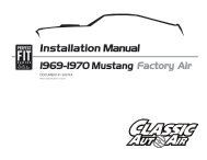
Installation Manual<br />
1968-1970 MOPAR B-BODY FACTORY AIR<br />
DOCUMENT #1-<strong>2066FA</strong><br />
©2013 <strong>Classic</strong><strong>Auto</strong><strong>Air</strong> / 6.13 vsA
www.classicautoair.com • 866.435.7801
PAGE<br />
3<br />
You have just purchased the highest quality, best performing<br />
A/C system ever designed for your Mopar.<br />
To obtain the high level of performance and dependability our systems are known for, please pay close attention to the<br />
following instructions. Our installation steps and procedures are derived from a long history of research and<br />
development and the combined experience achieved thru thousands of successful installations (and feedback from<br />
customers like you). Please remember that our #1 goal is that you’ll have a successful installation and a system that<br />
performs at a very high level for many years to come.<br />
Before starting, read the instructions carefully, from beginning to end, and follow the proper sequence. On the next<br />
page you’ll find a safety and general checklist that you should read before starting your installation.<br />
Again, thank you from our entire staff.<br />
www.classicautoair.com • 866.435.7801
PAGE<br />
4<br />
Check List, Pre-Installation:<br />
Before beginning the installation check the shipping box for the correct components. YOUR BOXED UNIT INCLUDES A LIST OF<br />
MAJOR COMPONENTS AND A LIST OF BAGGED PARTS. We have a 5 stage check process to make sure you have everything you’ll<br />
need.<br />
If your vehicle has been or is being modified, some procedures will need to be adjusted to fit your particular application.<br />
A basic cleaning of the engine compartment and interior before beginning will make things go more smoothly.<br />
Check condition of engine mounts. Excessive engine movement can damage hoses to A/C and/or heater.<br />
Before starting, check vehicle interior electrical functions (interior lights, radio, horn, etc). Make a note of anything that does not work as<br />
it’s supposed to. During the installation you might find the opportunity to repair or upgrade non-working or out of date components.<br />
When you’re ready to start the installation, DISCONNECT THE BATTERY FIRST.<br />
Drain the radiator. Retain the coolant and reuse, or dispose of properly.<br />
SAFETY FIRST: Wear eye protection while drilling/cutting, deburr sharp edges, and never get in a hurry or force a part.<br />
Tools: Your installation only requires the basic tools everyone has in their garage, nothing exotic or specific to A/C or Heat equipment.<br />
Procedures, During Installation:<br />
Fittings: Use one or two drops of mineral oil (supplied with your kit) on ALL rubber o-rings, threads and where o-rings seat in fittings. Do<br />
not use thread tape or sealants.<br />
Measure twice (or more), cut once<br />
Should you have any technical questions, or feel you have defective components (or missing items), call us immediately,<br />
we will be glad to assist you. Our toll-free number is listed on every page, we’re here to help!<br />
YOU CAN NOW BEGIN THE <strong>INSTALL</strong>ATION...<br />
www.classicautoair.com • 866.435.7801
PAGE<br />
5<br />
A Basic Overview of <strong>Auto</strong>motive A/C...<br />
1<br />
Evaporator with Blower Fan In order to remove the heat from the air in the vehicle, the<br />
A/C evaporator allows the refrigerant to absorb the heat from the air passing over it. The blower fan<br />
moves cool air out into the car interior.<br />
OUTSIDE AIR<br />
#8 Discharge Hose<br />
2<br />
Compressor The compressor pumps and circulates the refrigerant through the system.<br />
Suction<br />
Valve<br />
Discharge<br />
Valve<br />
3<br />
4<br />
5<br />
Condenser The condenser is a heat exchanger mounted at the front of the vehicle. Heat drawn<br />
out of the interior of the car is expelled here.<br />
Receiver/Drier The drier not only dries refrigerant, it also filters the refrigerant and stores it<br />
under certain operating conditions.<br />
High Pressure Switch A pressure switch is used to shut down the system if high or low<br />
pressure is detected, basically it acts as a safety switch.<br />
Receiver<br />
Drier<br />
#6 Liquid Hose<br />
Condenser<br />
Compressor<br />
#10 Suction Hose<br />
Firewall<br />
AIR FROM INSIDE VEHICLE<br />
Expansion Valve<br />
COOLED AIR<br />
1<br />
SUCTION HOSE<br />
LIQUID HOSE<br />
3<br />
2<br />
DISCHARGE HOSE<br />
5<br />
4<br />
POWER<br />
GROUND<br />
Evaporator Unit<br />
COLD AIR INTO VEHICLE<br />
The air conditioning system in your car is comprised of a compressor, condenser,<br />
expansion valve, receiver/drier, and evaporator. Refrigerant (also known as Freon) is<br />
compressed in the compressor and turns into a gas. In the condenser, this gas is cooled to<br />
a liquid state and travels to the expansion valve. As the liquid refrigerant goes through the<br />
expansion valve it rapidly cools in the evaporator. A fan blows over the evaporator and cools<br />
the air that blows out your vents. The receiver-drier separates gas and liquid.<br />
www.classicautoair.com • 866.435.7801
PAGE<br />
6<br />
CONTROL & OPERATING <strong>INSTRUCTIONS</strong><br />
Your new Perfect Fit-Elite system offers complete comfort capabilities in virtually every driving condition. This includes temperature control in all of the modes. This system also<br />
provides the ability to blend the air between Face, Heat, and Defrost modes simultaneously. To illustrate the various ways you can adjust the airflow direction and temperature -<br />
we’ve provided these handy illustrations and chart to show exactly how you can adjust your Perfect Fit-Elite for maximum comfort...<br />
NOTE: When the TEMP lever is<br />
in the FULL FOWARD (the<br />
coldest setting) position the<br />
compressor is ON, no matter<br />
what position the DASH / FLR<br />
lever is in (think of it as a<br />
compressor-override function)<br />
The FAN switch works<br />
like the OEM switch,<br />
the far FORWARD<br />
position is OFF (all<br />
power to the system is<br />
OFF in this position)<br />
There are 11 levels of adjustment within the<br />
range of the DASH/FLOOR lever<br />
DASH<br />
FLOOR<br />
DEF<br />
Lever Position<br />
1 2 3 4 5 6 7 8 9 10 11<br />
Distribution<br />
Face A/C<br />
100%<br />
Face<br />
80%<br />
Floor<br />
20%<br />
Face<br />
60%<br />
Floor<br />
40%<br />
Face<br />
40%<br />
Floor<br />
60%<br />
Face<br />
20%<br />
Floor<br />
80%<br />
Floor<br />
100%<br />
Floor<br />
80%<br />
Defrost<br />
20%<br />
Floor<br />
60%<br />
Defrost<br />
40%<br />
Floor<br />
40%<br />
Defrost<br />
60%<br />
Floor<br />
20%<br />
Defrost<br />
80%<br />
Defrost<br />
100%<br />
Compressor State<br />
ON<br />
ON<br />
www.classicautoair.com • 866.435.7801
PAGE<br />
7<br />
Remove Glove box, Glovebox door, Ashtray, and Radio, and OEM A/C controls<br />
(we provide our new D.E.R. controls). and set them aside for reinstall later (see<br />
figure 1). Note: If vehicle is equipped with a console, remove entire<br />
console and set aside.<br />
When retaining parts it’s a<br />
good idea to store parts in a<br />
zip lock bag, labeled with<br />
info where the parts came<br />
from and what size/type of<br />
tool is needed to reinstall. Cleaning<br />
the parts before you need to reinstall<br />
them is a good idea too.<br />
GOOD IDEA<br />
FIGURE 1<br />
Disconnect the electrical harness from the OEM assembly. Remove front support brace from the<br />
OEM unit (see figure 2). Retain the hardware (we will be providing a new support brace).<br />
FIGURE 2<br />
www.classicautoair.com • 866.435.7801
PAGE<br />
8<br />
Remove all the factory duct hoses and discard. Unhook the cable to the OEM heater valve and push the<br />
tout thru the firewall. Remove all 5 nuts that hold OEM A/C unit to firewall (see figure 3). At this point the<br />
OEM A/C unit should be free and you can remove from the vehicle. Nothing on the OEM unit will be reused<br />
on this installation.<br />
DRAIN COOLANT FROM RADIATOR. Store safely to reuse or recycle accordingly. Cut heater hose<br />
approximately 1” from firewall (see figure 5B). Also, to prevent forgetting to refill the coolant when the<br />
installation is completed, do not put the cap back into place - instead put the cap to the side and cover<br />
radiator hole with a clean rag or something similar.<br />
OEM Unit<br />
(Not reinstalled)<br />
Remove all 5 OEM nuts<br />
FIGURE 3<br />
www.classicautoair.com • 866.435.7801
PAGE<br />
9<br />
THESE ARE THE PARTS YOU WILL FIND IN BAG KIT A<br />
You will use all of these parts and hardware during the next series of installation steps.<br />
D.E.R. Controller<br />
PN# 16-3066<br />
Illustrations NOT shown actual size<br />
www.classicautoair.com • 866.435.7801
PAGE<br />
10<br />
FIGURE 4<br />
REMOVE THE OEM CONTROL HEAD FROM THE DASH (if you<br />
haven’t already).<br />
1) There are four screws that hold the OEM control unit in the dash.<br />
Remove the screws and set the assembly aside (see figure 4).<br />
2) Insert your new D.E.R. controller (feeding the wires in first) into the<br />
dash and secure with the OEM screws. You’ll connect the controller<br />
harness to our ECU a bit later.<br />
www.classicautoair.com • 866.435.7801
PAGE<br />
11<br />
THESE ARE THE PARTS YOU WILL FIND IN BAG KIT B<br />
You will use all of these parts and hardware during the next series of installation steps.<br />
Four #10 - 16 x 3/4" Tek Screws<br />
Evap Support Bracket<br />
PN# 0066-21<br />
Fresh <strong>Air</strong> Inlet Block Off<br />
PN# 10-1066-2<br />
Two #10 - x 3/8" Phillips Screws<br />
Three #10 - 10 x 5/8" Flange Nuts<br />
PN#25CNFLZ/S<br />
Two #8 - x 3/8" Phillips Screws<br />
One Male Spade Connector<br />
Defrost/Heat Duct Assembly<br />
PN# 2-2025-2<br />
Illustrations NOT shown actual size<br />
Two Fender Washers<br />
PN #0113-3<br />
www.classicautoair.com • 866.435.7801
PAGE<br />
12<br />
Locate the original wiring harness that supplied power to the OEM unit and cut them close<br />
to their end. On the OEM power supply wire attach a 1/4” insulated male spade connector<br />
(see figure 5).<br />
Within the OEM fuse box upgrade the factory HEATER fuse with a<br />
20 amp fuse (VERY IMPORTANT).<br />
FIGURE 5<br />
Locate behind dash and<br />
on firewall the hole that<br />
previously mounted the<br />
OEM unit.<br />
FIGURE 6<br />
SAMPLE<br />
Drill a 5/8” dia. hole for<br />
the drain tube as shown<br />
using the template we’ve<br />
provided (see figure 6).<br />
All preliminary modifications to the vehicle are complete.<br />
www.classicautoair.com • 866.435.7801
PAGE<br />
13<br />
A<br />
FIGURE 7<br />
Locate the fresh <strong>Air</strong> inlet block off. Install over hole in inlet cowl as shown. Attach with three<br />
#10 - 16 x 3/4" Tek Screws (see figure 7).<br />
Remove evaporator unit from box and place on a clean work bench.<br />
Locate defrost / heat duct assembly and attach to the evaporator using two #10 - 10 x 5/8"<br />
Phillips screws (see figure 8). NOTE: Be sure that the s-clips are pushed over rear flange<br />
on evaporator.<br />
Take a minute to familiarize yourself with the evaporator unit:<br />
Actuator Motor<br />
Rear Mounting<br />
Bracket<br />
Floor/Face<br />
Vent Door<br />
Blower Motor<br />
Bracket<br />
FIGURE 8<br />
Evaporator<br />
Support Bracket<br />
Holes<br />
Thermostat<br />
Blower Motor Plug<br />
www.classicautoair.com • 866.435.7801
PAGE<br />
14<br />
DASH<br />
FIREWALL<br />
Installing the complete evaporator unit under the dash will go much easier with the help of a<br />
friend. One person can take the unit within the car and “roll” up and under the dash while the<br />
other person can be ready at the firewall area with one or more of the included flange washers<br />
and nuts (the OEM hole are oversized and will require both a washer and flange nut for each).<br />
On back side of the evaporator is a mounting bracket with two studs. These studs will<br />
protrude thru the OEM holes (see figure 9).<br />
Next, attach the bracket located on the blower motor to the underside of the cowling with a<br />
tek-screw (as shown in figure 10).<br />
Now the unit will be easy to level and<br />
secure. Leveling the unit is<br />
very important to insure<br />
proper drainage of<br />
condensation (see below).<br />
FIGURE 10<br />
FIGURE 9<br />
Be sure to align<br />
the evaporator<br />
unit level with<br />
the bottom of<br />
instrument<br />
panel (assuming the vehicle<br />
is sitting level) as shown<br />
above, but with a small<br />
degree of tilt toward the<br />
back to allow proper drain<br />
of condensation.<br />
TECH TIPS<br />
LEVEL<br />
www.classicautoair.com • 866.435.7801
PAGE<br />
15<br />
We’ve included a new underdash evaporartor brace to replace the OEM one. Our new brace<br />
has a different bend and is an important replacement. Mount the brace to the new evaporartor<br />
as shown below, and use an included flange nut to secure (there is a OEM stud that you will<br />
use to secure the top of the bracket, see figure 11).<br />
IMPORTANT NOTE: On the side of the main unit you will see several holes for mounting<br />
holes... ONLY USE THE ONES ON THE FAR LEFT FOR THIS BRACKET! Do not tap into<br />
the other holes for any reason. Also, use a screwdriver and hand-power and do not<br />
over-tighten so you don't strip the holes (see figure 12).<br />
FIGURE 12<br />
YES<br />
NO!<br />
NO!<br />
FIGURE 11<br />
#8 x 3/8"<br />
Screws<br />
www.classicautoair.com • 866.435.7801
PAGE<br />
16<br />
THESE ARE THE PARTS YOU WILL FIND IN BAG KIT C<br />
You will use all of these parts and hardware during the next series of installation steps.<br />
Clear Plastic Drain Tube<br />
Firewall Block Off Plate<br />
PN #10-<strong>2066FA</strong>-2<br />
Electronic Water Control Valve<br />
PN# 16-1081-2<br />
Seven #10 - 16 x 3/4" Tek Screws<br />
Six Worm Gear Clamps<br />
Firewall Block Off<br />
PN# 10-<strong>2066FA</strong>-1<br />
Four Cap Plugs<br />
Illustrations NOT shown actual size<br />
Refrigerant Tape<br />
www.classicautoair.com • 866.435.7801
PAGE<br />
17<br />
In Bag Kit C you’ll find the firewall block off. Install this over the hose connections coming<br />
thru the firewall within the engine compartment. Attach with four Tek screws (see figure<br />
13). TIP: This would be a good time to “jump” ahead a bit, and remove the<br />
ORANGE cable from Bag Kit D and route it thru one of the OEM bolt holes (it will<br />
be plugged into the electronic water valve). Use the included cap plugs and seal<br />
off the remaining OEM holes.<br />
FIGURE 13<br />
IMPORTANT<br />
NOTICE: PROPER<br />
<strong>INSTALL</strong>ATION OF<br />
WATER VALVE<br />
<strong>INSTRUCTIONS</strong>!!!<br />
<strong>Classic</strong> <strong>Auto</strong> <strong>Air</strong> has done extensive testing on the correct<br />
method to install the water valve in order to get a<br />
repeatable and progressive temperature control. Your<br />
water valve MUST be installed per these<br />
instructions!... (if not, your system will not work<br />
properly... and that’s an absolute fact).<br />
The lower connection on the tubes coming thru the<br />
block off assembly is going to be routed to the water<br />
outlet on the intake manifold. Attach your hose with<br />
cable clamps on both ends and route where it will not<br />
interfere with linkage or come in contact with exhaust manifolds or headers.<br />
HEATER CORE<br />
FOLLOW THESE<br />
TAGS... CHECK IT<br />
TWICE BEFORE<br />
PROCEEDING!<br />
WATER PUMP<br />
FIGURE 14<br />
The upper port coming thru the firewall will be routed to and thru your new your<br />
electronic water valve (the water valve is marked for easy installation, see figure 14).<br />
First Attach a 6” piece of 5/8” dia. heater hose with the supplied worm gear clamp.<br />
Attach to the inlet side of the water valve using another supplied hose clamp. Attach a<br />
heater hose from the outlet side of the electronic water valve and route to the<br />
connection on the water pump.<br />
www.classicautoair.com • 866.435.7801
PAGE<br />
18<br />
FIGURE 15 FIGURE 16<br />
Insert a 6" piece of the clear drain tube we included<br />
through the hole previously drilled and attach over the<br />
drain nipple (see figure 15). Seal around tube hole with<br />
refrigerant tape (see figure 16).<br />
We’ve also included an additional block off plate to cover<br />
the OEM hole for the water valve and heater tubes. Use<br />
the remaining tek-screws to secure the new plate (see<br />
figure 17).<br />
FIGURE 17<br />
www.classicautoair.com • 866.435.7801
PAGE<br />
19<br />
THESE ARE THE PARTS YOU WILL FIND IN BAG KIT D<br />
You will use all of these parts and hardware during the next series of installation steps.<br />
The ECU will be in it’s own box, within this bag kit.<br />
WATER VALVE<br />
CONTROL<br />
POWER<br />
FACE/FLOOR<br />
DEFROST<br />
Two #10 - 16 x 3/4" Tek Screws<br />
Pressure Switch<br />
(engine compartment)<br />
Yellow<br />
Ground<br />
Ground<br />
Ground<br />
Orange<br />
ECU<br />
Blue<br />
Thermostat<br />
OEM Power<br />
Supply<br />
Fan<br />
Plug<br />
Wire Harness -<br />
Power Supply<br />
Blower Switch<br />
Connection<br />
Wire Harness System<br />
Relay<br />
Illustrations NOT shown actual size<br />
www.classicautoair.com • 866.435.7801
PAGE<br />
20<br />
OFF HEAT DEF<br />
DASH FLOOR<br />
DEF<br />
F<br />
A<br />
N<br />
We’ve included enough extra cable length to allow you to mount the ECU in a variety of<br />
places. It is very important that you mount this in a place where it will stay dry and that<br />
vibration is at a minimum. Also make sure that where ever you mount it it does not interfere<br />
with any moving controls or cables. We recommend mounting it just above the right hand side<br />
of the main unit using the included tek-screws. IMPORTANT! DON’T MOUNT THE ECU<br />
PERMANENTLY JUST YET. THAT CAN BE DONE AFTER YOU CALIBRATE THE UNIT .<br />
In Bag Kit D you will find three wiring harnesses with connections at each end. Plug the<br />
harness with YELLOW band into the YELLOW ECU port and the other end into the servo<br />
motor on the main unit (motor is marked with YELLOW INDICATOR). Repeat this process for<br />
the other two harnesses, following the color coding indicated on cables and ports. Attach<br />
cable in the engine compartment to the electronic water valve and route to one of the unused<br />
holes from the OEM unit.<br />
CONTROL HEAD: The GREEN harness connection will be made to the blower switch on the<br />
control head. Attach the connection to the blower switch, then insert the control head back<br />
into the dash and secure with the OEM screws. Make the final conection to the ECU at the<br />
GREEN port.<br />
Seal around the tubes with the included refrigerant tape. This will keep unwanted moisture and<br />
debris from entering thru the firewall... so seal carefully and thoroughly.<br />
www.classicautoair.com • 866.435.7801
PAGE<br />
21<br />
Wiring Diagram/Overview<br />
To 12V Power Supply (min. 20 amp fuse)<br />
Orange Harness<br />
Electronic Water Valve<br />
Red/White Wire<br />
Compressor<br />
Blower Switch<br />
Green Harness<br />
Blue Wires<br />
Ground<br />
Pressure Switch<br />
White Wire<br />
ECU<br />
D.E.R.<br />
Yellow Harness<br />
Servo for Face/Floor Ducts<br />
Blue Harness<br />
Evaporator<br />
Thermostat<br />
Ground<br />
Blue Wire<br />
Relay<br />
Red Wire<br />
Blue Wire<br />
Servo for Defrost Ducts<br />
Blue Wire<br />
Ground<br />
REMINDER: BE SURE THAT THE WIRING HARNESS DOES NOT INTERFERE WITH THE OPERATION OF ANY CONTROLS.<br />
www.classicautoair.com • 866.435.7801
PAGE<br />
22<br />
We’ve included enough extra cable length to allow you to mount the ECU in a variety of<br />
places. It is very important that you mount this in a place where it will stay dry and that<br />
vibration is at a minimum. Also make sure that where ever you mount it does not interfere with<br />
any moving controls or cables. We recommend mounting it just above the right hand side of<br />
the main unit using the included tek-screws. IMPORTANT! DON’T MOUNT THE ECU<br />
PERMANENTLY JUST YET. THAT CAN BE DONE AFTER YOU CALIBRATE THE UNIT<br />
(SEE NEXT PAGE).<br />
In Bag Kit D you will find three wiring harnesses with connections at each end. Plug the<br />
harness with YELLOW band into the YELLOW ECU port and the other end into the servo<br />
motor on the main unit (motor is marked with YELLOW INDICATOR). Repeat this process for<br />
the other two harnesses, following the color coding indicated on cables and ports. Attach<br />
cable in the engine compartment to the electronic water valve and route to one of the unused<br />
holes from the OEM unit. Using one of the CAP PLUGS provided, slot it and install over hole.<br />
NOTE: The GREEN harness connection will be made from the harness you previously<br />
installed, just plug the loose connection in the CONTROL port on the ECU. We’ve also<br />
included two other cap plugs you can use to seal unused holes.<br />
Seal around the tubes with the included refrigerant tape. This will keep unwanted moisture and<br />
debris from entering thru the firewall... so seal carefully and thoroughly.<br />
WATER VALVE<br />
CONTROL<br />
POWER<br />
FACE/FLOOR<br />
DEFROST<br />
FIREWALL<br />
www.classicautoair.com • 866.435.7801
PAGE<br />
23<br />
Temporarily reconnect the car battery at this time. You will need a full 12 volts to complete the calibration.<br />
WELCOME TO EZ CALIBRATION... Follow these directions carefully and your unit will be calibrated in just a few minutes.<br />
Before we boxed and shipped your unit, we tested and calibrated it to factory specifications to make sure it is capable of operating at maximum efficiency. However,<br />
the unit must still be calibrated to your specific vehicle and controls. This is an easy process that can be done in a few steps. If for any reason your unit does not<br />
calibrate properly the first time, just turn off the unit and rerun the setup process. NOTE: When you move a knob to a new position, do it in ONE continuous motion.<br />
#1 #2<br />
#3 #4<br />
TEMP<br />
FAN<br />
TEMP<br />
FAN<br />
TEMP<br />
FAN<br />
WATER VALVE<br />
MODE<br />
MODE<br />
MODE<br />
CONTROL<br />
POWER FACE/FLOOR DEFROST<br />
LED ON<br />
Calibration Key<br />
Plug CALIBRATION KEY into ECU<br />
Position your controls<br />
like this example.<br />
Move FAN control to medium<br />
in one motion...<br />
LED ON<br />
1 Second<br />
Later...<br />
LED OFF<br />
Move MODE control to<br />
DASH in one motion...<br />
1 Second<br />
Later...<br />
LED OFF<br />
#5 TEMP<br />
FAN #6<br />
After 1 second the<br />
#7 #8<br />
LED turns back ON<br />
TEMP<br />
FAN<br />
MODE<br />
MODE<br />
WATER VALVE<br />
LED ON<br />
1 Second<br />
Later...<br />
LED OFF<br />
LED ON<br />
CONTROL<br />
POWER FACE/FLOOR DEFROST<br />
Move TEMP control to<br />
HOT in one motion...<br />
You may be able to<br />
hear the internal door(s) move<br />
back and forth...<br />
Approx. 30<br />
Seconds<br />
Later...<br />
LED OFF<br />
Move the FAN knob to OFF<br />
(powers off unit)<br />
REMOVE KEY<br />
AND STORE IN<br />
SAFE PLACE<br />
Calibration Key<br />
That’s it. Your unit is now fully calibrated. Disconnect the battery and move on to the next phase....
PAGE<br />
24<br />
THESE ARE THE PARTS YOU WILL FIND IN BAG KITS E, F, and G<br />
You will use all of these parts and hardware during the next series of installation steps.<br />
Bag E<br />
Bag F<br />
Bag G<br />
Two Defrost Duct Adaptors<br />
PN #069-10<br />
Two Duct Adaptors<br />
PN# 2-<strong>2066FA</strong>-2<br />
Center Louver<br />
PN# 2-<strong>2066FA</strong>-3<br />
Two Duct Hoses, 2" I.D.<br />
Two Duct Hoses, 2" I.D.<br />
Two Duct Hoses, 2" I.D.<br />
Face Duct Assembly<br />
PN# 2-2025-1<br />
Four Zip-Ties<br />
Four Zip-Ties<br />
Four Zip-Ties<br />
Illustrations NOT shown actual size<br />
www.classicautoair.com • 866.435.7801
PAGE<br />
25<br />
Bag Kit E: The following steps are for left and right Defrost Diffusers: Locate and route the<br />
duct hoses from the defrost/heat duct assembly (see figure 18) upward toward the defrost<br />
adaptor diffusers. Next locate and install defrost adaptor diffusers from the top of the dash and<br />
secure with v-clips supplied. Attach flex hose to the defrost diffuser adaptors using zip-ties.<br />
Push adaptors onto diffusers from below. The other end of the duct hose is installed over the<br />
defrost/heat duct assembly outlets on main unit.<br />
The face duct assembly comes preinstalled with s-clips which allow you to install onto the<br />
evaporator unit quickly and securely (see figure 19).<br />
FIGURE 18<br />
OEM Defrost<br />
Vents<br />
S-clips (already installed)<br />
Defrost Adaptor Diffuser<br />
Duct Hose<br />
(Secured with zip-tie)<br />
Defrost Adaptor<br />
Diffuser<br />
Defrost Adaptor<br />
Reducer<br />
FIGURE 19<br />
www.classicautoair.com • 866.435.7801
PAGE<br />
26<br />
During installation of the hoses<br />
be aware of the eventual<br />
movement of the wiper arm<br />
components. Also, the<br />
smoother the route of the flex<br />
hoses the better the airflow.<br />
Bag Kit F: We’ve included two left and right (driver and passenger) side vent adaptors. These<br />
come pre-installed with clip that will allow you to simple press them onto the back of the OEM<br />
vents. Next you can attach duct hose to each and route to the diffuser (as shown in figure 19).<br />
TECH TIPS<br />
DRIVERS SIDE FLEX HOSE ROUTE<br />
PASSENGER SIDE<br />
FIGURE 19<br />
www.classicautoair.com • 866.435.7801
PAGE<br />
27<br />
LOUVER FLEX HOSE ROUTE<br />
CENT E R<br />
FIGURE 20<br />
Bag Kit G: In order to adapt to your OEM center louver you will need to utilize<br />
our center louver and adaptor. Remove the lower dash trim panel that contains<br />
the OEM center louver (see figure 20). Remove the OEM louver (retain the<br />
screws), insert your new center louver in it’s place and secure with the OEM<br />
screws (see figure 21).<br />
Go ahead and attach the duct hoses to the louver and route downward toward<br />
the evaporator, secure the duct hose at the louver with the included<br />
FIGURE 21<br />
www.classicautoair.com • 866.435.7801
PAGE<br />
28<br />
Reinstall any of the interior you may have removed. This is a<br />
good time to make a final check that all the controls still move<br />
freely and that nothing is loose or hanging down. This<br />
completes the interior portion of the PERFECT FIT-ELITE<br />
installation process.<br />
The interior of your car should look pretty much the same as<br />
before you started (or better). Plus you probably got to know the<br />
underside of your dash a lot better and might even have<br />
repaired or upgraded components that needed attention.<br />
Good Job... Let's move on to the major components within the engine<br />
compartment....<br />
GOOD IDEA<br />
Retaining all the<br />
non-reinstalled OEM parts is<br />
a good idea, but that’s your<br />
choice.<br />
www.classicautoair.com • 866.435.7801
PAGE<br />
29<br />
THESE ARE THE PARTS YOU WILL NEED FOR THE<br />
ENGINE COMPARTMENT <strong>INSTALL</strong>ATION<br />
You’ll find all of these parts within the main box<br />
Drier<br />
PN# 12-1008<br />
Condenser Bracket<br />
PN# 0066-52<br />
MDS-03 Insulation<br />
Switch Port Line<br />
PN# 0062-52<br />
Condenser<br />
PN# 11-1042<br />
Drier Bracket<br />
PN# 19-1001<br />
Condenser Bracket<br />
PN# 0066-51<br />
#8 Discharge Tube<br />
PN# 0066-53<br />
#6 Liquid Tube<br />
PN# 0062-50<br />
Four #10 X 1/4 Hex Head Screws<br />
Splice and<br />
Bullet Connector<br />
Condenser Bracket<br />
PN# 0066-50<br />
#6 Hose<br />
Clamp<br />
#6 5/16" Liquid Hose<br />
#8 Hose<br />
Clamp<br />
Four #10 - 16 x 3/4" Tek Screws<br />
Pressure Switch<br />
Two J-Clips<br />
#8 13/32" Discharge Hose<br />
#10 1/2" Suction Hose<br />
Four #1/4” 20 X 5/8” Bolts<br />
Two #1/4” x 20 Flange Nuts<br />
Bag of O-rings and<br />
Mineral Oil Tube<br />
Pressure Switch Harness<br />
Three Refrigerant Hoses<br />
www.classicautoair.com • 866.435.7801
PAGE<br />
30<br />
ENGINE COMPARTMENT <strong>INSTRUCTIONS</strong><br />
STEP ONE: IF YOU HAVE NOT ALREADY, DISCONNECT THE BATTERY.<br />
STEP TWO: During the next installation section you’ll be installing the condenser, drier, and routing the high/low pressure lines and the liquid line.<br />
Since much of this is installed in the OEM location for the condenser, you’ll need to remove the center grill section, horn(s), and latch support<br />
assembly. Be sure to retain all the mounting screws – you’ll reinstall these pieces in the exact reverse order with the OEM screws.<br />
STEP THREE: Time to install the compressor kit. Included in<br />
your box is a premium compressor kit with all the parts you’ll<br />
need to install the compressor. This kit includes easy to follow<br />
instructions specifically written for your engine. Once you’ve<br />
installed the complete compressor kit, continue on to the next<br />
step. We believe that this is the finest compressor kit available,<br />
and you’re bound to notice the excellent fit and quality once<br />
this step is completed.<br />
STEP FOUR: Install the Switch Port Line at the coming thru<br />
the firewall. Install the high pressure switch into the port on<br />
the Switch port line. NOTE: Tighten connections at either<br />
end using supplied o-rings on both ends and a few drops<br />
of mineral oil to each o-ring. Screw the high-pressure<br />
switch into the port at the lower end of the drier liquid<br />
tube. Go ahead and plug the pressure switch harness into<br />
the switch at this time (black electrical boot with two long<br />
white wires. see figure 22).<br />
FIGURE 22<br />
FIREWALL<br />
This will give you the correct location for installing the drier.<br />
Place the included drier bracket over the drier, and mount<br />
to the drier to the inner fender using the included<br />
tek-screws.<br />
TECH TIPS<br />
Reminder...<br />
Use two<br />
wrenches to<br />
tighten o-ring<br />
fittings<br />
www.classicautoair.com • 866.435.7801
PAGE<br />
31<br />
STEP FIVE: You can perform most of the following<br />
steps on a clean flat surface like a workbench.<br />
Lay the condenser down so that both hose<br />
connections are on the left side (the larger<br />
connection will be on top). Install the upper<br />
condenser brackets (A) using the included #10 x<br />
1/4 hex screws. Both brackets are installed at<br />
the very top of the condenser, and from the<br />
backside. These brackets have holes that exactly<br />
correspond to bolts that are in the OEM radiator<br />
support (see figure 23).<br />
STEP SIX: We’ve included a new lower condenser<br />
bracket (B). Locate the lower mounting bracket<br />
to bottom rail in front of the radiator. Attach two<br />
¼”-20 j-clip to the frame rail over the existing<br />
holes, and secure with two 1/4” x 20 x 5/8” hex<br />
screws. We’ve included a piece of MDS03<br />
insulation with a self-adhesive back. Peel the<br />
backing off and place into the upper channel of<br />
the lower bracket (this will reduce vibration, see<br />
figure 24).<br />
STEP SEVEN: Place the condenser into place and<br />
secure with a ¼”-20 x 5/8” hex head screw and<br />
a 1/4 x 20 flange nut thru the existing holes in<br />
the radiator support on both sides (both brackets<br />
are secured in the same way).<br />
#1/4” 20 X 5/8”<br />
Bolts<br />
FIGURE 24<br />
MDS03 INSULATION<br />
A<br />
B<br />
#10 X 1/4<br />
Hex Head Screws<br />
CONDENSER<br />
#1/4” x 20 Flange Nut<br />
RADIATOR SUPPORT<br />
#10 X 1/4<br />
Hex Head Screws<br />
A<br />
#1/4” x 20 Flange Nut<br />
FIGURE 23<br />
#1/4” 20 X 5/8”<br />
Bolts<br />
www.classicautoair.com • 866.435.7801
PAGE<br />
32<br />
#10 - 16 x 3/4"<br />
Tek Screws<br />
STEP EIGHT: You can now jog the discharge and liquids lines thru<br />
the existing upper rectangular hole in the radiator support, and<br />
then secure to the condenser. The longer line will be attached<br />
to the lower port on the condenser. The shorter line is attached<br />
to the upper port on the condenser. Test fit the routing before<br />
securing the fittings (see figure 25). NOTE: Tighten connections<br />
at either end using supplied o-rings on both ends and a few<br />
drops of mineral oil to each o-ring.<br />
HOSE CLAMPS<br />
FIGURE 26<br />
BATTERY<br />
INNER FENDER<br />
We’ve included two hose clamps which you can use to secure<br />
the lines to the drivers side inner fender area. Secure clamps<br />
with two #10 x 3/4” tek-screws (see figure 26).<br />
Discharge Tube<br />
FIGURE 25<br />
TECH TIPS<br />
Reminder...<br />
Use two<br />
wrenches to<br />
tighten o-ring<br />
fittings<br />
Liquid Tube<br />
www.classicautoair.com • 866.435.7801
PAGE<br />
33<br />
STEP NINE: CONNECTING THE HOSES (see figure 27):<br />
1) Attach the #8 Discharge Hose (13/32") from the<br />
connection coming thru the support and route to the<br />
compressor. Tighten fittings using o-rings and mineral oil<br />
provided.<br />
2) Attach the #6 liquid hose (5/16") from the connection<br />
coming thru the support and route to the connection<br />
evaporator unit (see figure 41). Tighten fittings using<br />
o-rings and mineral oil supplied in kit.<br />
FIGURE 27<br />
3) Attach the #10 suction hose (1/2”) to the compressor<br />
and route to the last remaining connection<br />
coming thru the firewall. Tighten fittings<br />
using o-rings and mineral oil<br />
supplied in the kit.<br />
TIPS: Route your lines so they will not interfere<br />
with moving parts or fall onto excessively hot<br />
components.<br />
Double check all fittings before the initial<br />
servicing of your system. Loose fittings are the<br />
number one cause of leaks.<br />
SERVICE PORT<br />
COMPRESSOR<br />
SERVICE PORT<br />
www.classicautoair.com • 866.435.7801
PAGE<br />
34<br />
STEP TEN: Connecting the wires from the pressure switch will be done as follows, connect one<br />
wire to the connection on the compressor, and the other wire will be routed along with the<br />
liquid hose and connected to the blue lead you left unconnected during the interior installation.<br />
We’ve included a bullet and slice connector to make these connections, use a crimp tool to<br />
secure these properly. You must run the white switch wire thru the firewall and connect to the<br />
blue wire from the main harness.<br />
FINAL STEPS: You can now complete this portion of the installation by reinstalling any of the<br />
exterior components you removed. Take a look around at your installation and check all fitting<br />
and bolts for tightness, check the heater hose clamps for tightness, and make sure nothing is<br />
routed in a way to obstruct any moving parts.<br />
You can refill the radiator and reconnect the battery at this time.<br />
WAY TO GO! You’ve just completed the installation of your new A/C system.<br />
The final step is to fully charge and test your new system.<br />
On the next page you’ll find specifications for<br />
proper final preparation for your A/C technician.<br />
www.classicautoair.com • 866.435.7801
PAGE<br />
35<br />
www.classicautoair.com • 866.435.7801
PAGE<br />
36<br />
New A/C System Preparation... A MUST READ!<br />
Please read thru these procedures before completing this new A/C system charging operation.<br />
A licensed A/C technician should be utilized for these procedures to insure<br />
that your new system will perform at it’s peak, and that your compressor will<br />
not be damaged.<br />
Centerline of the Oil Plug<br />
90˚<br />
90˚<br />
1) Your radiator/cooling system is an integral part of your new system. Please insure that<br />
you have a 50/50 mix of distilled water and antifreeze. The heater coil MUST be purged<br />
(cycle heater control valve) to make sure no water, without antifreeze, is in the heater coil<br />
before you charge the A/C system.<br />
2) Evacuate the system for 45 minutes (minimum).<br />
3) Your new compressor MUST be hand-turned 15-20 revolutions before<br />
and after charging with liquid. Failure to do this may cause the reed<br />
valves to become damaged (this damage is NOT covered by your warranty).<br />
4) Your new system requires 134a refrigerant. It will require 1.5 lbs (or 24 oz).<br />
5) Your new compressor comes charged with oil - NO additional oil is needed.<br />
6) Insure that the new belt is tight.<br />
7) DO NOT CHARGE SYSTEM WITH LIQUID WHILE THE ENGINE IS RUNNING!<br />
RECOMMENDED TEST CONDITIONS: (After system has been fully charged and tested for basic operation)<br />
• Determine the temperature outside of the car<br />
• Connect gauges or service equipment to high/low charging ports<br />
• Place blower fan switch on medium<br />
• Close all doors and windows on vehicle<br />
• Place shop fan directly in front of condenser<br />
• Run engine idle up to approx. 1500 rpm<br />
ACCEPTABLE OPERATING PRESSURE RANGES:<br />
1. HIGH-SIDE PRESSURES (150-250 PSI)<br />
2. LOW-SIDE PRESSURES (15-25 PSI in a steady state)<br />
Readings above are based on an ambient temperature of 90˚ with an adequate airflow on condenser<br />
CAUTION! When mounting your compressor<br />
and/or adjusting the belt, use caution not to tilt<br />
the compressor up to or more than 90˚ off the<br />
centerline of the oil fill plug. This can cause<br />
compressor failure.<br />
! Do NOT tilt, shake or<br />
turn refrigerant can<br />
upside-down OR use a<br />
charging station to<br />
install refrigerant while<br />
the engine is running. Doing<br />
so will direct liquid refrigerant into the<br />
compressor piston chamber, causing damage<br />
to reed valves and/or pistons and/or other components,<br />
as well as potentially seizing the compressor. Allow a<br />
minimum of 30 minutes for liquid to "boil off.” You must<br />
hand turn the compressor hub (not the pulley) a<br />
minimum of 15 complete revolutions prior to starting<br />
the engine with the clutch engaged.<br />
www.classicautoair.com • 866.435.7801
PAGE<br />
37<br />
TEST CONDITIONS USED TO DETERMINE SYSTEM OPERATION<br />
(THESE TEST CONDITIONS WILL SIMULATE THE AFFECT OF<br />
DRIVING THE VEHICLE AND GIVE THE TECHNICIAN THE THREE<br />
CRITICAL READINGS THAT THEY WILL NEED TO DIAGNOSE ANY<br />
POTENTIAL PROBLEMS).<br />
B. CONNECT GAUGES OR SERVICE EQUIPMENT TO HIGH/LOW<br />
CHARGING PORTS.<br />
C. PLACE BLOWER FAN SWITCH ON MEDIUM.<br />
D. CLOSE ALL DOORS AND WINDOWS ON VEHICLE.<br />
E. PLACE SHOP FAN IN FRONT OF CONDENSER.<br />
F. RUN ENGINE IDLE UP TO 1500 RPM.<br />
ACCEPTABLE OPERATING PRESSURE RANGES (R134A TYPE)<br />
1. HIGH-SIDE PRESSURES ( 150-250 PSI ) *Note- general rule of thumb is<br />
two times the ambient (daytime) temperature, plus 15-20%.<br />
2. LOW-SIDE PRESSURES ( 15-25 PSI in a steady state).<br />
CHARGE AS FOLLOWS: R134A = 24 OZ.<br />
NO ADDITIONAL OIL IS NECESSARY IN OUR NEW COMPRESSORS.<br />
TYPICAL PROBLEMS ENCOUNTERED IN CHARGING SYSTEMS<br />
NOISY COMPRESSOR. A noisy compressor is generally caused by charging a compressor with<br />
liquid or overcharging<br />
A. If the system is overcharged both gauges will read abnormally high readings. This is<br />
causing a feedback pressure on the compressor causing it to rattle or shake from the<br />
increased cylinder head pressures. System must be evacuated and re-charged to exact<br />
weight specifications.<br />
B. Heater control valve installation - Installing the heater control valve in the incorrect hose.<br />
Usually when this occurs the system will cool at idle then start to warm up when raising the<br />
RPM’s of the motor. THE HEATER CONTROL IS A DIRECTIONAL VALVE; MAKE SURE THE<br />
WATER FLOW IS WITH THE DIRECTION OF THE ARROW. As the engine heats up that water<br />
transfers the heat to the coil, thus overpowering the a/c coil. A leaking or faulty valve will<br />
TROUBLESHOOTING GUIDE<br />
have a more pronounced affect on the unit’s cooling ability. Installing the valve improperly<br />
(such as having the flow reversed) will also allow water to flow through, thus inhibiting<br />
cooling. Check for heat transfer by disconnecting hoses from the system completely. By<br />
running down the road with the hoses looped backed through the motor, you eliminate the<br />
possibility of heat transfer to the unit.<br />
C. Evaporator freezing - Freezing can occur both externally and internally on an evaporator<br />
core. External freeze up occurs when the coil cannot effectively displace the condensation<br />
on the outside fins and the water forms ice (the evaporator core resembles a block of solid<br />
ice), it restricts the flow of air that can pass through it, which gives the illusion of the air not<br />
functioning. The common cause of external freezing is the setting of the thermostat and the<br />
presence of high humidity in the passenger compartment. All door and window seals should<br />
be checked in the event of constant freeze-up. A thermostat is provided with all units to<br />
control the cycling of the compressor.<br />
D. Internal freeze up occurs when there is too much moisture inside the system. The<br />
symptoms of internal freeze up often surface after extended highway driving. The volume of<br />
air stays constant, but the temperature of the air gradually rises. When this freezing occurs<br />
the low side pressure will drop, eventually going into a vacuum. At this point, the system<br />
should be checked by a professional who will evacuate the system and the drier will have<br />
to be changed.<br />
E. Inadequate airflow to condenser - The condenser works best in front of the radiator with<br />
a large supply of fresh air. Abnormally high pressures will result from improper airflow.<br />
Check the airflow requirements by placing a large capacity fan in front of the condenser<br />
and running cool water over the surface. If the pressures drop significantly, this will indicate<br />
the need for better airflow.<br />
F. Incorrect or inadequate condenser capacity - Incorrect condenser capacity will cause<br />
abnormally high head pressures. A quick test that can be performed is to run cool water<br />
over the condenser while the system is operating, if the pressures decrease significantly, it<br />
is likely a airflow or capacity problem.<br />
G. Expansion valve failure - An expansion valve failure is generally caused by dirt or debris<br />
entering the system during assembly. If an expansion valve fails it will be indicated by<br />
abnormal gauge readings. A valve that is blocked will be indicated by high side that is<br />
unusually high, while the low side will be unusually low or may even go into a vacuum. A<br />
valve that is stuck open will be indicated by both the high and low pressures rising to<br />
unusually high readings, seeming to move toward equal readings on the gauges.<br />
H. Restrictions in system - A restriction in the cooling system will cause abnormal readings<br />
on the gauges. A high-side restriction ( between the compressor and the drier inlet ) will be<br />
indicated by the discharge gauges reading excessively high. These simple tests can be<br />
performed by a local shop and can help determine the extent of the systems problem.<br />
www.classicautoair.com • 866.435.7801
PAGE<br />
38<br />
Trouble Shooting Your <strong>Classic</strong> <strong>Auto</strong> <strong>Air</strong> A/C System<br />
PROBLEM: system is not cooling properly<br />
ISSUE: cold at idle, warmer when raising engine RPM’s<br />
Make sure the Water Valve is positioned correctly<br />
The water valve is a directional valve and should be installed with the arrow pointing towards the<br />
water pump, it should be connected to the heater hose that runs from the heater core to the<br />
water pump. If the water valve is connected to the incorrect hose it allows water to circulate<br />
through the system via the heater core over powering the cooling effect of the A/C coil, (normally<br />
the air conditioning is functioning properly).<br />
Step 1: Check placement of the water valve, correct if needed. (In some cases changing the<br />
location of the water valve may not fix the above problem.) Continue to next step.<br />
Step 2 If changing the location of the water valve does not rectify the issue, then possibly the<br />
water valve is permanently damaged and may need to be replaced. To check the integrity of the<br />
water valve completely remove the water hoses for the heater core and “loop” together. (This will<br />
remove the heater system completely from the possibilities) If the system now cools, replace the<br />
water valve<br />
Verify Adequate <strong>Air</strong> Flow to Condenser<br />
For an air conditioning system to function properly there has to be adequate airflow across<br />
the condenser. The function of the condenser is to dissipate heat, without proper<br />
airflow your system will not cool correctly in the cabin of your vehicle.<br />
Step 1: connect gauges to a/C hoses. The pressures should be: with the ambient temp is<br />
90, low side pressures should be between 8-25 psi, high side pressures should be<br />
between 160-260psi<br />
Step 2: IF the low side pressures are normal and the high side pressures are high then<br />
there might be an airflow issue, continue to next step.<br />
If the paper is held in place you are at least getting some air flow. If the high side<br />
decreases during test 2 & 3 then your condenser is not getting enough air which is<br />
causing your system to not cool properly. To correct this issue you will need a more<br />
powerful mechanical fan.<br />
Step 3: Confirm correct Refrigerant charge in System<br />
All of our systems should be charged with 24oz or 1.8lbs of R134 Refrigerant only. If<br />
overcharged you will need to evacuate the system and recharge with the correct<br />
amount.*<br />
What measurements mean:<br />
Low Temp and High Pressure seem to be equal...<br />
You have a malfunctioning expansion valve that is stuck open.<br />
High Side is extremely high and Low Side is extremely low (possibly into vacuum)...<br />
There is a blockage in the system. Remove hoses and blow compressed air through in both<br />
directions. If pressures don’t change its possible that your expansion valve is stuck<br />
closed and would have to be replaced.<br />
*Compressor Concerns:<br />
This is often misdiagnosed as a problem for the system not cooling properly. If you have a noisy<br />
compressor it is due to improper charging of refrigerant. An overcharged (more than 24oz or<br />
1.8lbs R134) compressor can cause rattling. If charged with pure liquid there is a high probability<br />
you have bent reed valves that are causing tapping sound.<br />
To test air flow to Condenser do the following three tests:<br />
1. Place a piece of paper on the condenser with the car in idle and see if paper is held in<br />
place.<br />
2. With car in idle, attach gages, and place a large capacity fan in front of the condenser.<br />
What happens to the pressures?<br />
3. With car still in idle and gages attached, pour water down the front of the condenser.<br />
What happens to the pressures?<br />
www.classicautoair.com • 866.435.7801
THIS TEMPLATE IS USED<br />
FROM THE INSIDE OF THE CAR!<br />
IF YOU PRINTED THIS MANUAL<br />
PLEASE READ THIS...<br />
Just as a cautionary step, please<br />
measure this box and make sure it<br />
is 1” x 1”. Some copiers/printers<br />
may not print at 100% of actual size.<br />
HEATER MOTOR<br />
HOLE<br />
O.E.M. HOLE<br />
5/8”<br />
NEW DRAIN TUBE<br />
HOLE<br />
Note: bottom of template is parallel with floor pan LEVEL