1961-64 Ford Pickup Truck - Classic Auto Air
1961-64 Ford Pickup Truck - Classic Auto Air
1961-64 Ford Pickup Truck - Classic Auto Air

You also want an ePaper? Increase the reach of your titles
YUMPU automatically turns print PDFs into web optimized ePapers that Google loves.
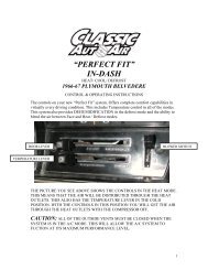
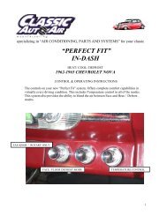
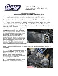
specializing in “AIR CONDITIONING, PARTS AND SYSTEMS” for your classicvehicle“PERFECT FIT”IN-DASHHEAT/ COOL/ DEFROST1960-66 FORD PICKUPCONTROL & OPERATING INSTRUCTIONSThe controls on your new “Perfect Fit” system. Offers complete comfort capabilities in virtuallyevery driving condition. This includes Temperature control in all of the modes.This system also provides the ability to blend the air between Face and Heat / Defrost modes.THE PICTURE YOU SEE ABOVE SHOWS THE CONTROLS IN THE FACE MODE.THIS MEANS THAT THE AIR WILL BE DISTRIBUTED THROUGH THE FACEOUTLETS. THIS ALSO HAS THE TEMPERATURE LEVER IN THE COLDPOSITION. WITH THE CONTROLS IN THIS POSITION YOU WILL GET THE AIRTHROUGH THE FACE OUTLETS WITH THE COMPRESSOR ON.1
CAUTION: ALL OF THE OUTSIDE VENTS MUST BE CLOSED WHEN THESYSTEM IS IN THE A/C MODE. THIS WILL ALLOW THE A/C SYSTEM TOFUCTION AT ITS MAXIMUM PERFORMANCE LEVEL.THE FOLLOWING SUMMARY WILL DESCRIBE EACH OF THE CONTROLLEVERS FUNCTION.FAN SPEED SWITCH: There are 3 speeds plus Off. When the switch is in the offposition it will disconnect the 12V power to the Blower Motor and the A/C Clutch. Thiswill shut down the entire system. When the switch is moved to any of the blower speeds1, 2 or 3 there is 12V supplied to the Micro-Switch that is mounted on the main housing.FACE AND FLOOR / DEFROST MODE: When the push pull cable is pulled allthe way OUT, it will direct the air to the floor / and defrost ducts. The cable can bemoved any position from full in to full out. This will give blend between all distributionoutlets.TEMPERATURE CONTROL: The temperature Knob as shown is in theCOLDEST temperature position. As the lever is pulled out the temperature of thedischarged air will rise to the HOTTEST point.Note: The temperature lever will function in any of the modes.AIR CONDITIONING MODE: The picture shows the Knob in the Face Mode(air-flow out the face outlets).When the Mode control knob is pushed all the way IN the <strong>Air</strong> Conditioning is activatedthe compressor clutch is on. When the compressor is activated the Temperature Leverwill control the air from maximum cold through maximum heat.2
specializing in “AIR CONDITIONING, PARTS AND SYSTEMS” for your classicvehicleINSTALLATION INSTRUCTIONS<strong>1961</strong>-<strong>64</strong> FORD PICKUPCongratulations!! You have just purchased the highest quality, best performing A/Csystem ever designed for you <strong>Classic</strong> <strong>Truck</strong>. To obtain the high level of performance anddependability our systems are known for, pay close attention to the following instructions.Before beginning the installation check the box for the correct components.EvaporatorFace Duct AssemblyDefrost Duct AssemblyFlex Hose 2”dia. x 1ft.Flex Hose 2”dia. x 2ft.Flex Hose 2”dia. x 3ft.Flex Hose 2”dia. x 4ft.Sack Kit HardwareSack Kit ControlGlove BoxIMPORTANT INFORMATION1. Before starting, read the instructions carefully and follow proper sequence.2. Check condition of engine mounts. Excessive engine movement can damagehoses to A/C, heater, radiator, transcooler, and power steering systems.3. Before starting, check vehicle interior electrical functions. i.e. interior lights,radio, horn, etc. When ready to start installation, disconnect battery.4. Fittings. Use one or two drops of lubricant on O’rings, threads and rear of bumpfor O’ring where female nut rides. Do not use thread tape or sealants.5. Always use two wrenches to tighten fittings. Try holding in one hand whilesqueezing together while other hand holds fitting in position.6. Shaft seals in a small percentage of compressors will require as much as 3-4hours run time to become leak free.7. Compressors supplied in our complete systems are filled with proper amount ofoil.8. Compressor requires technician to hand turn 15-20 revolutions before and aftercharging with liquid from a charging station before running system.Compressors with damaged reed valves cannot be warranted.9. Should you have any technical questions, or are suspect of missing, or defectiveparts, call us immediately. Our knowledgeable staff will be glad to assist you.YOU CAN NOW BEGIN THE INSTALLATION3
CAUTION: DISCONNECT BATTERY GROUND CABLERemove Glove box door, and glovebox. Retain the glove box door and alloriginal hardware. Discard the glovebox housing.Located on engine side of firewall is thebattery. Disconnect and remove battery, andbattery tray.Retain the original hardware.Located on engine side of the firewall.Drain radiator and then remove heaterhoses from the heater connections.COVER DOMERemove the blower motor cover dome anddiscard cover but retain original hardware.4
Also remove (3) nuts that attach the heaterassembly to the firewall.312Located on engine side of firewall and behind thethrottle linkage, is a nut. Remove this nut and discard.Located on top, drivers side of the heaterassembly remove the defrost ducts and discard.Also disconnect the control cable and discardthe hardware.5
Located on top of heater looking through theglove box opening.Disconnect wires from the heater.Remove and discard heater assembly..Located on the instrument panel is the originalheater blower switch and cable combination.Remove the control knob as shown.Located on back of the switch is a Brown wire.Disconnect from the switch. This is the power wirefor the new heater / a/c unit.Remove the entire assembly along with originalwire harness and discard.6
Locate on top of the dash (2) defrost outlets. Remove the cover and the flex hose adapter.Retain the cover and all of its hardware. Discard flex hose adaptor.Locate on passenger kick panel thefresh air inlet door. Carefully bend thecable bracket up 90 deg. as shown.REMOVEINSULATI0NBEND CABLE BRACKETUP. AT THIS POINT7”Located on the inside of the firewall behind the glove box.Remove 7” of the original insulation. As shown.7
The modifications to the vehicle are complete. You can now begininstalling your new <strong>Classic</strong> <strong>Auto</strong> <strong>Air</strong> “Perfect Fit Series” system..Locate in the hardware sack kit (2) Defrost hose adapters. Also locate the 2” dia. x 12”and 2” x 24” flex hose.Use (1) piece 12” long and attach to one of the hose adapter using (2) #8 x ½” pan head phillipsscrew. Use (1) piece 24” long and attach to the other hose adapter using (2) #8 x ½” pan headphillips screw.Insert the 11” assembly in the right hole in top of the dash and attach along with original defrostgrills and original hardware. The 24” assembly goes in the left hole.#8 x ½” SCREWLocate the Evaporator from the kit. Carefully set the Evaporator on a bench.Locate in the Control Sack Kit shortest of the (2) Control cables. Insert cable in to the Door crank inthird hole from the end as shown. Using (1) #10 x 5/8”. Pan Head Phillips screw attach cable clip tothe attachment bracket.Locate the Defrost Duct Assembly and (2) #10 x 5/8” pan head screws from the hardware sack kit.Attach duct to the rear support bracket as shown.8
The evaporator has A/C tubes that will insert through originalheater tube holes in the firewall. Locate the J-clipson the rear mounting bracket. Align clips to the originalheater mounting holes in the firewall.Attach using (3) ¼” – 20 x 5/8” hex head bolts and ¼” flatwashers provided in the hardware sack kit.NOTE: THE LIQUID A/C TUBE HAS (2) LARGE WASHERS. REMOVE THE NUTS ON THEBULKHEAD FITTINGS AND INSTALL (1) WASHER BEFORE INSERTING TUBESTHROUGH FIREWALL.Heater tubes will insert through the firewallhole as shown.Reinstall large washer and nut over the liquidtube assembly.Reinstall the suction tube nut. Tighten bothnuts securely.HEATER TUBESLIQUID TUBE & WASHERSAlso locate in the Hardware Sack Kit (1) #10 x ¾” Hex HeadTek Screw. Locate Black wire with Ring Terminal from theblower motor. Attach the wire as shown.Locate and drill (1) 11/16 dia. hole in firewallunder evaporator 4” and a little down from theheater connection.Locate in the hardware sack kit (1) 9” piece of5/8 dia. drain tube. Attach over drain nippleand through the hole.9
Locate in the hardware sack kit the firewall cover plate.Attach over heater tubes using the original hardware.Locate support bracket under the glove boxopening.Attach to bottom of instrument panel using(1) #10 x ¾” tek screw supplied.Locate 2” dia. flex hose that is attached to the defrosthose adaptors.Attach over the defrost duct as shown.Route Wire Harness and the control cable that is attached tothe evaporator over the dash brace.10
Locate the Blower Switch and (2) switch nuts. Attach blower switch to the wire harness using thediagram below.BROWN WIRELocate brown wire that attached to theoriginal blower switch. Cut off the terminaland attach a ¼” male spade connector.Locate red / white stripped wire on the wireharness and plug it into the brown wire.Locate the Temperature Control cable inthe control sack kit. Route the cable backtowards firewall. You will find the originalhole that supported the original heaterassembly. Pass cable through the hole andthen out through firewall and over to theheater tubes.BLOWER SWITCHWIRING DIAGRAM <strong>1961</strong>-<strong>64</strong> FORD TRUCKWIRING DIAGRAM / 1966 FORD PICKUP11
Locate the Face Duct Assembly from the unit box. Slide over outlet on the evaporator.Attach to bottom edge of the dash using (2) #10 x ¾” tek screw.Look behind the control bracket you will find (2) holes. Using (2) #10 x ¾” tek screws attachbracket to bottom of the dash.Attach Blower Switch, Heat cable assembly, and Temperature cable assembly to the control bracket.As shown below.(2) #10 X ¾ TEK SCREWS BEHIND CONTROL BRACKETTEMP HEAT FAN SWITCHCABLE CABLE (2) #10 X ¾” TEK SCREWSNOTE: CHECK “HEAT” CABLE FOR SMOOTH OPERATION AND FULL DOOR TRAVEL.Locate Center Louver Bezel. Attach over front ofoutlet.Use (3) #8 x ½” pan head philips screws.Locate in the Control Sack kit the (3) Knobs.Attach to control cables and blower switchusing an allen wrench.12
Locate in kit. Passenger side Ball Louver and the 2” dia.x 36” flex hose. Remove the ball louver and retain.Locate (2) #10 x ¾” hex head tek screw and attachHousing to Passengers Kick Panel through the openingin front.Reattach ball louver assembly.Cut 27” of flex hose and attach to outlet ontop of center duct just inside the glove box.Route up and over glove box opening and down.Attach to passengers side louver.Locate drivers side louver. Attach to drivers kickpanel as you did the passenger louver.Locate remaining 2” dia. x 48” flex hose and cut to44”. Attach to hose adaptor on back of the louver.Route flex hose from drivers louver up and behindinstruments, then down and connect to the centerduct outlet13
Install Glove Box Door using the originalhardware.NOTE: DOOR SPRINGLocate New Glove Boxand install using originalhardware.CAUTION: The control cables are equipped with inline adjusters. Adjust the Defrost, Heat/ Face door, and Water valve cable so that full travel of the Control cable, operates the door toits full travel. Make sure that water valve completely closes when cable is in the cold position.The Micro Switch that is mounted on the Face / heat door is used to turn on the compressorclutch. This will occur when the control lever is in the face position. It may be necessary toadjust thin metal arm on the switch. Make sure that Clutch Micro Switch is depressed whenlever is in the face position.The engine compartment components should be installed at this time.Carefully follow the electrical diagram provided on page 11.COMPRESSOR MOUNTING COMPONENTS WILL DIFFER DEPENDING ON THE ENGINEAND DRIVE ACCESSORIES THAT YOUR VEHICLE IS EQUIPED WITH. FOLLOWINGINSTRUCTIONS SHOW THE PROPER INSTALLATION SEQUENCE FOR THIS VEHICLE14
Remove original fan, fan shroud, drainand remove radiator. Retain all originalhardware.Locate following components from the under hood components box.CondenserReceiver Drier / Hi –Low pressure switchDrier mounting bracketDischarge TubeLiquid Tube (2)(4) Condenser mounting brackets(10) #10 x 3/8 hex washer head screwsLocate Condenser, (2) Lower condenser mounting brackets, Liquid Tube (Condenser to Drier),Liquid Tube ( Drier to Liquid Hose) and reciever drier with mounting bracket.15
Attach these components on condenser as shown above. Use (2) #6 o-ring and a few drops ofmineral oil.Attach condenser brackets and the drier bracket to the condenser using (6) #10 x 3/8” hex headscrews.Locate the Hi / Low Pressure switch.Attach to port on top of the Drier using a few drops of mineraloil. Tighten securly.Locate in the hardware sack kit (2) ¼ - 20 j-clips.Located at bottom of the radiator opening are (2) holes.Push the j-clips over holes as shown.NOTE: CONDENSER BRACKETS MOUNT BEHIND THE BULKHEAD AND BEHIND THEGRILL.Locate and remove the Hood Latch Assembly. Retain original hardware.Modify latch assembly as shown. Reinstall using original hardware.CUT ¼”16
Place condenser assembly from engine side ofbulkhead into the opening in the bulkhead.Locate lower condenser mounting brackets asshown.Locate in the hardware sack kit (2) ¼” –20 x 5/8”hex head screws. Attach the lower (2) condensermounting bracketsLocate in the condenser sack kit, (2) #10 x ¾” hex headtek screws. Attach to upper bulkhead as shown.Locate the Discharge Tube (1/2” dia.), ½”hose clamp, (1) ¼” – 20 x 5/8” screw, and (1)¼” – 20 flange nut.Attach tube to upper condenser fitting andinsert through hole in the bulkhead as shown.Using (1) #8 o-ring and few drops of mineraloil.17
Located behind the grill.Drill 9/32” hole in line with tube clamp andfasten to the bulkhead as shown.Locate the Liquid Hose; attach one end to the tube asshown.Route hose along bulkhead and attach to the LiquidTube from the receiver / drier. Attach using (2) #6 o-rings and a few drops of mineral oil.Locate (1) 3/8” dia hose clamp, (1) ½” dia. hoseclamp, and (2) #10 x ¾” hex head tek screws.Attach liquid tube and hose assembly to the bulkheadas shown.Locate the Suction Hose andattach end with service port tothe Compressor. Route the hoseback and along firewall acrossand down to #10 bulkheadfitting on the firewall.Attach using (2) #10 o-ring andfew drops of mineral oil.18
Locate the Discharge Hose.Attach straight fitting to tubefrom the condenser and 90 deg.with service port to thecompressor. Attach using (2)#8 o-rings and a few drops ofmineral oil.Locate electrical plug thatattaches to pressure switch onthe drier. Route along dischargehose to the compressor.There are two white wires attached to the pressure switch route one of them to the compressor clutchand attach a female bullet connector. The other wire route along suction hose and attach to clutchwire at the firewall. Secure wires with tywraps provided.Hookup heater hoses to the connections coming through the firewall.NOTE: SUPPLY LINE FROM ENGINE WILL BE HOOKED TO THE TOP FITTING USING AWORM GEAR CLAMP.CONTROL CABLEIt is recommended that the heater hoses bereplaced at this time.Using the same refrigeration tape, seal around the cable and clutch wire.Locate in the Hardware Sack Kit the WaterValve and (3) worm gear clamps. Cut 6” offof the return heater hose and attach to theconnector then to the water valve and then tothe remaining hose that goes back to theengine. Use the worm gear clamps supplied.Locate control cable that was passed throughthe firewall. Attach end to the water valve asshown. Be sure that control knob is pushed inall the way and water valve is in the fullclosed position.19
Reinstall battery box, battery, radiator, fan shroud, fan assembly, hookup radiator hoses and refillwith coolant.THE ENGINE COMPARTMENT OF YOUR SYSTEM IS COMPLETE.THE UNIT IS READY FOR EVACUATION AND CHARGING.THIS SHOULD BE DONE BY A QUALIFIED AND CERTIFIED AIRCONDITIONING TECHNICIAN.NOTE: COMPRESSOR IS SUPPLIED WITH THECORRECT OIL CHARGE. DO NOT ADD OIL TO SYSTEM.134a SYSTEMS 24 oz OF REFRIGERANTRecommend that power fuse is 25amp minimumCongratulations you have completed the install of yourCLASSIC AUTO AIR “Perfect Fit Series” system.20
IMPORTANTCAUTION: WATER VALVE MUST BE INSTALLED PER THEINSTRUCTIONS.<strong>Classic</strong> <strong>Auto</strong> <strong>Air</strong> has done extensive testing on the correct method to install the water valve in order to get a repeatableand progressive temperature control.Locate the bottom connection from the evaporator/heater unit off of the firewall and attach a 6” piece of 5/8” dia. heaterhose with the supplied hose clamp. Next attach the inlet side of the water valve using another supplied hose clamp,(make sure the arrow on the water valve points toward the engine) Attach a heater hose from the outlet side of the watervalve and route to the connection on the water pump.NOTE: WATER VALVE = WATER PUMPFROM HEATER CORETO WATER PUMPCAUTION: WATER VALVE MUST BE INSTALLED ON HEATER LINE ROUTED TO WATERPUMP.NOTE: COMPRESSOR PURCHASED WITH KIT ISSUPPLIED WITH THE CORRECT OIL CHARGE. DO NOTADD OIL TO SYSTEM.134A SYSTEMS 24 oz OF REFRIGERANTRecommend that power fuse is 25amp minimum21