
You also want an ePaper? Increase the reach of your titles
YUMPU automatically turns print PDFs into web optimized ePapers that Google loves.
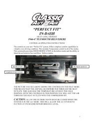
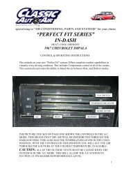
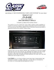
specializing in “AIR CONDITIONING, PARTS AND SYSTEMS” for your classicvehicle“PERFECT FIT”IN-DASHHEAT/ COOL/ DEFROST<strong>1961</strong>-<strong>63</strong> FORD THUNDERBIRDCONTROL & OPERATING INSTRUCTIONSThe controls on your new “Perfect Fit” system. Offers complete comfort capabilities in virtuallyevery driving condition. This includes Temperature control in all of the modes.This system also provides DEHUMIDIFICATION in the defrost mode.THE PICTURE YOU SEE ABOVE SHOWS THE CONTROLS IN THE A/C MODE.THIS MEANS THAT THE AIR WILL BE DISTRIBUTED THROUGH THE FACEOUTLETS. THIS ALSO HAS THE TEMPERATURE LEVER IN THE COLDPOSITION. WITH THE CONTROLS IN THIS POSITION YOU WILL GET THE AIRTHROUGH THE FACE OUTLETS AT THE COLDEST TEMPERATURE.1
CAUTION: ALL OF THE OUTSIDE VENTS MUST BE CLOSED WHEN THE SYSTEMIS IN THE A/C MODE. THIS WILL ALLOW THE A/C SYSTEM TO FUCTION AT ITSMAXIMUM PERFORMANCE LEVEL.THE FOLLOWING SUMMARY WILL DESCRIBE EACH OF THE CONTROL LEVERSFUNCTION.FAN SPEED SWITCH: There are 3 speeds plus Off. When the switch is in the off position itwill disconnect the 12V power to the Blower Motor and the A/C Clutch. This will shut down theentire system. When the switch is moved to any of the blower speeds 1, 2 or 3 there is 12Vsupplied to the Micro-Switch that is mounted on the Defrost Duct.FACE / DEFROST / HEAT DOOR CONTROL: When the Control Knob is pushed allthe way to the LEFT the air is distributed to the FACE outlets. In the FACE position thecompressor is engaged. When the knob is pushed to the MIDDLE of the controls the air will go tothe DEFROST outlets. In the Defrost position the compressor clutch is engaged fordehumidification. When the knob is pushed all the way to the RIGHT the air will go to the HEAToutlets.TEMPERATURE CONTROL: The Temperature Knob as shown is at the COLDESTtemperature position. As the lever is PUSHED to the LEFT the temperature of the discharged airwill RISE to the HOTTEST point.Note: The temperature lever will function in any of the modes.2
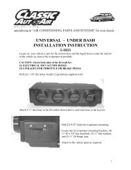
specializing in “AIR CONDITIONING, PARTS AND SYSTEMS” for your classicvehicleINSTALLATION INSTRUCTIONS<strong>1961</strong> - <strong>63</strong> FORD THUNDERBIRDCongratulations!! You have just purchased the highest quality, best performing A/C system everdesigned for you <strong>Classic</strong> Car. To obtain the high level of performance and dependability oursystems are known for, pay close attention to the following instructions.Before beginning the installation check the box for the correct components.EvaporatorDistribution Duct AssemblyFlex Hose 2”dia. (4 ea) x 2 ft.Flex Hose 2 1/2” dia. (2 ea) x 1ft.Block off <strong>Air</strong> InletSack Kit HardwareSack Kit ControlControl Cables (2)IMPORTANT INFORMATION1. Before starting, read the instructions carefully and follow proper sequence.2. Check condition of engine mounts. Excessive engine movement can damagehoses to A/C, heater, radiator, transcooler, and power steering systems.3. Before starting, check vehicle interior electrical functions. i.e. interior lights,radio, horn, etc. When ready to start installation, disconnect battery.4. Fittings. Use one or two drops of lubricant on O’rings, threads and rear of bumpfor O’ring where female nut rides. Do not use thread tape or sealants.5. Always use two wrenches to tighten fittings. Try holding in one hand whilesqueezing together while other hand holds fitting in position.6. Shaft seals in a small percentage of compressors will require as much as 3-4hours run time to become leak free.7. Compressors supplied in our complete systems are filled with proper amount ofoil.8. Compressor requires technician to hand turn 15-20 revolutions before and aftercharging with liquid from a charging station before running system.Compressors with damaged reed valves cannot be warranted.9. Should you have any technical questions, or are suspect of missing, or defectiveparts, call us immediately. Our knowledgeable staff will be glad to assist you.YOU CAN NOW BEGIN THE INSTALLATION3
Remove (4) mounting bolts thathold the panel to the dash.Remove (2) mounting bolts on drivers side of the center mountingplate.Remove (2) mounting blots on the bottom of center mountingplate.Retain all original hardware.Disconnect control cables on both sides ofthe control head. Retain screws and theclips.Disconnect electrical plug from back ofthe switch.There is a ground wire attached to thecontrols. Remove and discard screw.Carefully remove lights from the controlhead.5
Carefully snap off chrome framearound the control head.Retain for reinstallation.Remove (4) screws holding the controlhead to the center mounting plate.Remove center mounting plate andretain hardware.Disconnect electrical harness from the heater box.ELECTRICAL PLUGDrain radiator. Disconnect heater hoses at the firewall.It is recommended that you replace the heater hose from theengine at this time.6
Remove blower motor access cover andremove (4) nuts that attach the heater box tothe firewall. Next picture shows location ofthe nuts. Retain original screws discard thenuts.CAREFULLY REMOVE HEATER ASSEMBLYFROM UNDER THE DASH. DISCARD HEATERASSEMBLY.Locate air inlet flange assemblydirectly above the passenger kickpanel.Remove (4) screws and discard theinlet flange.Locate in the kit the inlet block offplate. Attach plate to the inlet holeusing (4) #10 tek screws supplied.Locate the firewall block off plate.Attach over blower access hole using (1)¼” – 20 bolt and nut through the originalheater mounting hole.Other (4) screws are the original coverfasteners.¼ - 20 x 5/8”BOLT & NUTTTACH OVERMatch drill holes into the firewall thatthe heater hoses will pass through. (13/8” dia)Install grommets over the holes.(2) HOSE GROMMETS7
Locate the drain tube template on last page of the instructions.Tape template on the firewall. Locate the original heatermounting hole. Align template to this hole and along bend in thefirewall.Drill a ¾” diameter hole as shown.CUT WIRES HERELocate wire harness that was attached to the controls.Peel tape back all the way to the junction. Separate the lightwire. Cut switch wires at the junction.Also cut off the resistor wires and plug.RESISTORWIRESLocate wire assembly that was attached to the blower motor.Cut the black wire off.Remove the bullet connector and attach (1) ¼” male spadeconnector. Both wires will be crimped into the sameconnector.8
Locate original control head assembly.Remove and discard the vacuum switch assembly.Using an allen wrench carefully remove theblower switch knob. Retain knob.Remove and discard original blower switch andscrew.ORIGNAL SWITCH MOUNTING HOLELocate blower switch mounting template fromlast page of the instructions.Tape template over back of the control head.Locate template over the original switchmounting hole.DRILL (2) 1/8” DIA HOLESDrill (2) 1/8” diameter holes as shown.Locate the blower switch, (2) #6 x 3/8” pan head screwand (4) flat washers.Attach the switch to back of the control assembly using#6 screws and (2) flat washers as spacers per screw.Install original switch knob onto new switch.9
Locate (2) control cables and (2) 3/16” push nuts supplied in the kit.LONGEST of the cables is the temperature control cable. Lay control assembly on the bench as shown inthe picture below. Attach this cable to right control lever using original cable clip, screw and push nut.Cable housing is located along edge of the bracket.DOOR CONTROL CABLE¾”TEMPERATURE CABLELOCATE AT EDGESHORTEST of the cables is the door control cable. Lay control assembly on the bench as shown in thepicture above. Attach this cable to left control lever using the original cable clip, screw and push nut.Cable housing is located ¾” past edge of the bracket.Place control assembly in the car with the cablesrouted as per the picture to the right.Reinstall lights to the control head.Locate the wire harness from the kit.Attach harness to the blower switch perwiring diagram on the next page. Connectred /white striped wire to the originalblower power wire.10
(2) ON TOP AND (2) ON BOTTOMLocate the evaporator, <strong>Air</strong> Distribution Ductassembly and (4)#10 x 5/8” pan head screws.Place evaporator on the bench and attach Distributionassembly onto evaporator using (4) #10 x 5/8” panhead screws.Locate (2) 2” diameter flex hose, (2) hose adaptersand (8) #8 X 3/8 pan head screws.Cut (1) piece 16” long, (1) piece 20” long and attachthem to the hose adapters using (2) pan head screws.Attach 16” hose to rear defrost outlet using #8 screws.Attach 20” hose to front defrost outlet using #8screws.Locate the evaporator. Slide evaporator underthe instrument panel and up into place.Follow directions on the next page for properinstall.12
Insert a/c tubes and heater hoses through thefirewall cover plate.Locate (1) ¼”- 20 x 5/8” hex head bolt.Attach evaporator rear mounting bracket to theblock off using the 1/4” bolt.Attach mounting bracket on the blower to edge of theair inlet block off using (1) #10 x ¾” tek screw.Reinstall center mounting plate using original screws.Attach (2) left and bottom (2) screws at this time.Reattach control head using the original hardware.Loosely attach front evaporator mounting bracketthrough center mounting plate and into dash using (1)of the original bolts.13
Route short defrost flex hose over top of theevaporator and push over the defrost diffuser.Longest defrost flex hose routes over to the driversdefrost diffuser.Locate ground wire from the servo motorassembly and (1) #8 x 3/8” screw and nut.Attach ground wire to center mounting plate atthe recessed hole.Route wire harness over top of the evaporator to the blower motor.Attach connectors to the motor, thermostat, and resistor.Refer to electrical diagram.Attach ground wire from blower connector to thebody using (1) #10 tek screw.14
Reinstall passenger side dash panel usingoriginal hardware.It is necessary to remove the bolt holdingthe front evaporator bracket. This bolt goesthrough the panel, bracket and intothreaded part of the dash.Locate the louver cutout template.Tape template to center of the trimpanel.Carefully cut out (3) holes. Using a 2 ½”diameter hole saw.8”14”8”Locate (2) ball louvers with 2 ½”dia hose adapters.Locate (1) ball louver with 2”hose adapter.Attach 2” louver through thecenter hole. The 2 ½” louversattach through outside holes.Locate 2 ½” dia flex hose x 1ft.and cut (2) pieces 8” long.Slide over the 2 ½” hose adaptorand attach using (2) #8 x 3/8” panhead screws16
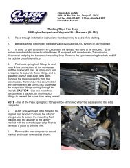
Turn condenser over so that fittings are onthe right side.Attach top condenser brackets to top holeof the condenser, using #10 screwsLocate the drier, drier mounting bracket, pressure switch, (1) #6 liquid tube (short),(1) liquid tube(long), (4) #6 o-rings and (2) #10 x 3/8” hex screws.Attach discharge tube to #8 fittingon condenser using an o-ring and afew drops of mineral oil.Attach short liquid tube to #6fitting on condenser using o-ringand a few drops of mineral oil.Other end attaches to the to thedrier inlet.PRESSURE SWITCHUse the tube to locate drier andmounting bracket. Attach using#10 screws.Attach long liquid tube to the drierusing a #6 o-ring and a few dropsof mineral oil.Slide condenser between radiator and the radiator bulkhead.Let condenser hange on the upper brackets.Install pressure switch on filter drier. Attach the electricalboot to the pressure switch, route white wires across thedischarge tube. Tywrap wires to the tube.18
Locate left bottom condenser mounting bracket and slideinto the bottom radiator mounting bolt.Attach right bottom condenser mountingbracket over the 5/16” bolt.Tighten the condenser bolts.Locate (1) 3/8” tube clamp and (1)#10 x ¾” tek screw.Attach liquid tube to the radiator support usingclamp and screw.REINSTALL RADIATOR FAN AND SPACER USING THE ORIGINAL HARDWARE.19
Locate #6 liquid hose and (2) #6 o-rings. Attach hose between fitting on firewall andfitting on the condenser.Locate #10 suction hose and (2) #10 o-rings. Attach hose to fitting on the block off andend with the service port to the compressor.When routing liquid hose attachhose and the return heater hoseto the shock tower using (1)double clamp and a #10 tekscrew.When routing suction hosetywrap the hose to the bodybrace beside the air cleaner.SUCTIONHOSEDISCHARGEHOSELocate #8 discharge hose and (2) #8 o-ring.Attach end of hose with 45 deg fitting to thecondenser fitting and the end with the service portto the compressor.Reinstall top radiator cover panel using originalhardware.Locate discharge tube support bracket, #8 hoseclamp and (1) #10 x 3/8” pan head screw.Attach bracket to top radiator cover panel. Alsoattach clamp over discharge tube and onto bracketusing the #10 screw.20
Locate (2) white wires tywraped to the discharge tube. Route along the discharge hose. Cut oneof the wires and attach female bullet connector provided and plug into the compressor clutchwire.Other wire route along suction hose and connect to blue clutch wire from the thermostat.Attach water valve to lower hose from theevaporator using (2) worm gear clamps.Other end of water valve attaches to thereturn line to the motor.Attach control cable to the water valve. Besure that temperature lever has full traveland that the valve closes completely.Short hose connects to supply line from themotor.CAUTION: CHECK AROUND ENGINE TO BE SURE THATTHERE IS NOTHING THAT WILL INTERFER WITH SAFE OPERATION OF THEVEHICLE.THE ENGINE COMPARTMENT OF YOUR SYSTEM IS COMPLETE.THE UNIT IS READY FOR EVACUATION AND CHARGING.THIS SHOULD BE DONE BY A QUALIFIED AND CERTIFIED AIRCONDITIONING TECHNICIAN.TO WATER PUMPNOTE:COMPRESSORIS SUPPLIEDWITH THECORRECT OILCHARGE. DONOT ADD OILTO SYSTEM.134a SYSTEMS24 oz OFREFRIGERANTRecommendthat power fuseis 25amp21
IMPORTANTCAUTION: WATER VALVE MUST BE INSTALLED PER THEINSTRUCTIONS.<strong>Classic</strong> <strong>Auto</strong> <strong>Air</strong> has done extensive testing on the correct method to install the water valve inorder to get a repeatable and progressive temperature control.Locate the bottom connection from the evaporator/heater unit off of the firewall and attach a 6”piece of 5/8” dia. heater hose with the supplied hose clamp. Next attach the inlet side of the watervalve using another supplied hose clamp, (make sure the arrow on the water valve points towardthe engine) Attach a heater hose from the outlet side of the water valve and route to the connectionon the water pump.NOTE: WATER VALVE = WATER PUMPFROM HEATER CORETO WATER PUMPNOTE:COMPRESSORIS SUPPLIEDWITH THECORRECT OILCHARGE. DONOT ADD OILTO SYSTEM.CAUTION: WATER VALVE MUST BE INSTALLED ON HEATER LINE ROUTED TO WATERPUMP.NOTE: COMPRESSOR PURCHASED WITH 134a SYSTEMS KIT ISSUPPLIED WITH THE CORRECT OIL CHARGE. 24 oz DO OF NOTADD OIL TO SYSTEM. REFRIGERAN134A SYSTEMS 24 oz OF REFRIGERANT TRecommend that power fuse is 25amp minimum Recommendthat power fuse22