Standard (22-132) 1. Read through installation ... - Classic Auto Air
Standard (22-132) 1. Read through installation ... - Classic Auto Air
Standard (22-132) 1. Read through installation ... - Classic Auto Air

You also want an ePaper? Increase the reach of your titles
YUMPU automatically turns print PDFs into web optimized ePapers that Google loves.
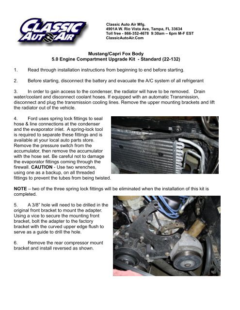
<strong>Classic</strong> <strong>Auto</strong> <strong>Air</strong> Mfg.<br />
4901A W. Rio Vista Ave, Tampa, FL 33634<br />
Toll free - 866-352-4678 9:30am – 6pm M-F EST<br />
<strong>Classic</strong><strong>Auto</strong><strong>Air</strong>.Com<br />
Mustang/Capri Fox Body<br />
5.0 Engine Compartment Upgrade Kit - <strong>Standard</strong> (<strong>22</strong>-<strong>132</strong>)<br />
<strong>1.</strong> <strong>Read</strong> <strong>through</strong> <strong>installation</strong> instructions from beginning to end before starting.<br />
2. Before starting, disconnect the battery and evacuate the A/C system of all refrigerant<br />
3. In order to gain access to the condenser, the radiator will have to be removed. Drain<br />
water/coolant and disconnect coolant hoses. If equipped with an automatic Transmission,<br />
disconnect and plug the transmission cooling lines. Remove the upper mounting brackets and lift<br />
the radiator out of the vehicle.<br />
4. Ford uses spring lock fittings to seal<br />
hose & line connections at the condenser<br />
and the evaporator inlet. A spring-lock tool<br />
is required to separate these fittings and is<br />
available at your local auto parts store.<br />
Remove the pressure switch from the<br />
accumulator, then remove the accumulator<br />
with the hose set. Be careful not to damage<br />
the evaporator fittings coming <strong>through</strong> the<br />
firewall. CAUTION - Use two wrenches,<br />
using one as a backup, on all threaded<br />
fittings to prevent the tubes from being twisted.<br />
NOTE – two of the three spring lock fittings will be eliminated when the <strong>installation</strong> of this kit is<br />
completed.<br />
5. A 3/8” hole will need to be drilled in the<br />
original front bracket to mount the adapter.<br />
Using a vice to secure the mounting front<br />
bracket, bolt the adapter to the factory<br />
bracket with the curved upper edge flush to<br />
serve as a guide to drill the hole.<br />
6. Remove the rear compressor mount<br />
bracket and install reversed as shown.
The bracket is still installed on the engine<br />
in the previous photo. The adapter bracket<br />
will mount between the factory brackets as<br />
shown.<br />
7. THIS STEP IS A COSMETIC<br />
OPTION ONLY, AND NOT REQUIRED<br />
FOR FIT OR FUNCTION PURPOSES - To<br />
improve the appearance of the <strong>installation</strong>,<br />
you can trim the factory bracket as shown.<br />
If you are unable to cut this bracket, please<br />
skip to the next step.<br />
The photo at left shows the piece trimmed from the<br />
original mounting bracket.<br />
This photo to the right shows the finished piece after<br />
trim & painting.<br />
8. Replace the front mounting bracket on<br />
the engine using the original hardware. Using<br />
the supplied hardware, install the adapter<br />
brackets on the factory brackets as shown.<br />
Bolt the front adapter behind the front factory<br />
bracket, and the rear adapter (they are<br />
identical) to the front of the rear factory<br />
bracket. Do not tighten these bolts yet.
9. Using the supplied hardware, install the compressor<br />
as shown.<br />
10. In order to attach the clutch wire, you will need to<br />
cut the original power lead to the compressor, tape off the<br />
ground wire (solid black) and connect the clutch wire to<br />
the remaining wire using the included terminal.<br />
1<strong>1.</strong> Install the 3/16” spacers<br />
between the adapter brackets and the<br />
mounting ears of the compressor. This<br />
will ensure correct belt alignment.<br />
Tighten all bolts.<br />
12. Install the new serpentine belt<br />
supplied in the kit.<br />
13. Install the correct size o-ring on the<br />
discharge hose, add a few drops of oil, and<br />
attach to the discharge fitting on the<br />
compressor. Be sure to orient the fitting as<br />
shown to clear the distributor.
14. Install the correct size o-ring on the<br />
suction hose, add a few drops of oil, and<br />
attach to the suction fitting on the<br />
compressor.<br />
15. Install the new condenser using the<br />
original hardware.<br />
16. Re-install the radiator, radiator hoses,<br />
water/coolant, automatic transmission<br />
cooling lines (if so equipped) and the upper<br />
mounting brackets.<br />
17. Before installing the accumulator/suction hose and liquid hose, it’s important to insure that<br />
the evaporator is clean and free of contaminants. It may simply need to be blown <strong>through</strong> with<br />
compressed air, but if contaminated oil or debris is found, removal for flushing or replacement<br />
may be necessary. Due to the evaporator design, the evaporator cannot be flushed without<br />
removing.<br />
18. Once the evaporator has been determined contaminant free or replaced, install o-ring on<br />
the connections and lubricate with a few drops of the supplied assembly oil. It can be helpful to<br />
lubricate the threads of the fittings as well.<br />
19. Install and lubricate an o-ring on the fitting off of the accumulator, then attach to the top<br />
fitting on the evaporator fitting at the firewall. Install the pressure switch on the new accumulator<br />
and attach the wire harness. Do no tighten fitting yet.
20. The suction hose is pre-crimped on the accumulator and will be routed as shown to the<br />
large suction fitting on the compressor. Install and lubricate an o-ring and attach to the<br />
compressor.<br />
2<strong>1.</strong> Once routing of suction hose is complete, tighten<br />
the connection at the evaporator and the compressor.<br />
The liquid hose assembly has a fitting in the middle<br />
where the orifice tube is installed. Install & lubricate an<br />
o-ring and assemble the two hoses as shown and<br />
assemble as shown. Do not tighten fittings yet. Lay the<br />
hose assembly in position with the 45’ spring-lock end<br />
toward the evaporator, taking care to insure the hose<br />
assembly is routed clear of the exhaust.<br />
<strong>22</strong>. Install & lubricate an o-ring on the<br />
straight end and connect the straight fitting<br />
to the condenser at the core support. Do<br />
not tighten fittings yet.
23. Lubricate and install an o-ring, then<br />
connect the 45’ spring lock fitting to the<br />
evaporator’s bottom fitting at the firewall<br />
next to the accumulator as shown. Press<br />
firmly, you will feel a “click” when the spring<br />
lock fittings are seated properly. Tug at the<br />
fittings to be sure they are fully locked. They<br />
should not come apart when pulled.<br />
24. Tighten fitting at the condenser and<br />
the two hoses where they join together.<br />
CAUTION - Use two wrenches, using one<br />
as a backup to prevent the tubes or fittings<br />
from being twisted.<br />
NOTE – This is the only remaining spring-lock fitting<br />
remaining in the system.<br />
25. The discharge hose connects the<br />
compressor to the condenser. Install &<br />
lubricate an o-ring to the 45’ fitting and<br />
install on the compressor discharge fitting.<br />
NOTE - Make certain you orient the fitting at<br />
the compressor end as shown to clear the<br />
distributor. Tighten the fitting upon positioning.<br />
26. Lubricate and install an o-ring on the straight fitting<br />
(has a service port on it) and connect to the top fitting of the<br />
condenser. Tighten the fitting.<br />
27. Reconnect battery.<br />
After installing the kit, you will need to have the system<br />
evacuated and charged by a qualified A/C technician.<br />
There is no need to add oil to the system as the proper<br />
amount is in the compressor.<br />
REGULARLY UPDATED INSTALLATION INSTRUCTIONS CAN BE DOWNLOADED AT<br />
http://www.classicautoair.com/downloads/ecu/23-<strong>132</strong>.pdf