GPTLR SERIES (2010 Release) - Maxon
GPTLR SERIES (2010 Release) - Maxon
GPTLR SERIES (2010 Release) - Maxon

You also want an ePaper? Increase the reach of your titles
YUMPU automatically turns print PDFs into web optimized ePapers that Google loves.
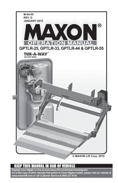
M-04-05<br />
REV. G<br />
JANUARY <strong>2010</strong><br />
OPERATION MANUAL<br />
<strong>GPTLR</strong>-25, <strong>GPTLR</strong>-33, <strong>GPTLR</strong>-44 & <strong>GPTLR</strong>-55<br />
© MAXON Lift Corp. <strong>2010</strong>
TABLE OF CONTENTS<br />
WARNINGS .............................................................................4<br />
LIFTGATE TERMINOLOGY ....................................................5<br />
RECOMMENDED DAILY OPERATION CHECKS ..................6<br />
DECALS ..................................................................................8<br />
NONSKID & STRIPING ...........................................................12<br />
FORKLIFT ADVISORY ...........................................................13<br />
ROADSIDE OPERATION ADVISORY ....................................14<br />
OPERATION ...........................................................................15<br />
USING STANDARD CART STOPS (IF EQUIPPED) ..............23<br />
USING BACK CART STOPS (IF EQUIPPED) ........................26<br />
USING RETENTION RAMP (IF EQUIPPED) ..........................30
WARNINGS<br />
!<br />
WARNING<br />
1. Incorrect operation of this Liftgate can result in serious personal<br />
injury. Comply with WARNINGS and Liftgate operating instructions<br />
in this manual. Do not allow untrained persons or children to operate<br />
the Liftgate. If you need to replace an Operation Manual, additional<br />
copies are available from:<br />
MAXON Lift Corp.<br />
11921 Slauson Ave<br />
Santa Fe Springs, CA 90670<br />
(800) 227-4116<br />
NOTE: For latest version manuals (and replacements), download<br />
manuals from <strong>Maxon</strong>’s website at www.maxonlift.com.<br />
2. Do not exceed rated load capacity of the Liftgates which is 2500 lbs.<br />
for model <strong>GPTLR</strong>-25, 3300 lbs. for model <strong>GPTLR</strong>-33, 4400 lbs.<br />
for model <strong>GPTLR</strong>-44, and 5500 lbs. for model <strong>GPTLR</strong>-55.<br />
3. Do not allow any part of your body to be placed under, within, or<br />
around any portion of the moving Liftgate or its mechanisms, or in<br />
a position that would trap them between the platform and the fl oor<br />
of truck body (or between platform and the ground) when Liftgate is<br />
operating.<br />
4. Consider the safety and location of bystanders and<br />
location of nearby objects when operating the Liftgate. Stand<br />
to one side of platform while operating the Liftgate. Be certain<br />
that the area the Liftgate will move through during operation<br />
is clear of all obstacles.<br />
5. Comply with all attached instruction decals and warning decals.<br />
6. Keep decals clean and legible. If decals are illegible or missing,<br />
have them replaced. Get free replacement decals from <strong>Maxon</strong>.<br />
7. Never drive a forklift on the Liftgate platform.<br />
8. Do not move vehicle unless Liftgate is correctly stowed.<br />
9. Correctly stow platform when not in use. Extended platforms<br />
could create a hazard for people and vehicles passing by.<br />
10. A correctly installed Liftgate will operate smoothly and reasonably<br />
quiet. The only noticeable noise, during Liftgate operation, is from<br />
the pump unit while the platform is raised. Listen for scraping,<br />
grating and binding noises and have the problem corrected<br />
before continuing to operate the Liftgate.<br />
11. Above all, USE GOOD COMMON SENSE when operating this<br />
Liftgate.<br />
12. Never use a cell phone while operating the Liftgate.<br />
4
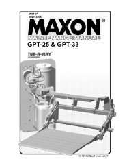
LIFTGATE TERMINOLOGY<br />
EXTENSION<br />
PLATE<br />
LIFT<br />
CYLINDER<br />
CONTROL<br />
SWITCH<br />
PARALLEL<br />
ARM<br />
SPRING ASSIST<br />
TORSION BAR<br />
PUMP<br />
BOX<br />
HYDRAULIC<br />
LOCK VALVE<br />
FLIPOVER WITH<br />
FIXED RAMP<br />
PLATFORM<br />
PLATFORM<br />
OPENER<br />
MAIN<br />
FRAME<br />
LIFT<br />
ARM<br />
5
RECOMMENDED DAILY OPERATION CHECKS<br />
NOTE: Before you check the Liftgate, park vehicle on fl at ground and<br />
set the parking brake.<br />
NOTE: If any of the following operation checks reveal a need to<br />
service or repair Liftgate, do not operate the Liftgate until a<br />
qualifi ed mechanic services or repairs the Liftgate.<br />
Before operating the Liftgate, the operator should do the following:<br />
Make sure battery is fully charged and battery terminal connections are<br />
clean and tight.<br />
Make sure cab cutoff switch is ON, if equipped.<br />
Visually check that pump cover is bolted on securely and undamaged.<br />
Look for hydraulic fl uid leaking from the pump box.<br />
Visually check that control switch is in place and undamaged.<br />
Visually check for cracks and bends on the extension plate. Also, make<br />
sure fasteners are in place and undamaged and extension plate is<br />
clean (no oil, debris, or corrosion).<br />
Visually check that all decals, nonskid stickers, and safety striping are<br />
in place (see DECALS and NONSKID & SAFETY STRIPING pages).<br />
Also, make sure decals are legible and decals, nonskid, and safety<br />
striping are clean and undamaged.<br />
Use the operation instructions in this manual to lower the Liftgate to<br />
the ground and open the platform and flipover.<br />
Check main frame, lift arms, parallel arms and platform openers for<br />
cracks and bends. Make sure rollers, on the platform openers, roll<br />
freely. Also, make sure all bolts and pins are in place and undamaged.<br />
Make sure main frame, lift arms, parallel arms and platform openers<br />
are clean (no oil, debris, or corrosion).<br />
Check the hydraulic cylinders for leaking seals and hose connections.<br />
Follow the hydraulic hoses (or return lines for gravity down Liftgates)<br />
from the cylinders to pump box. Make sure all hoses are connected at<br />
both ends and there are no cracks, chafi ng, and fl uid leaks.<br />
6
NOTE: Liftgates may be equipped with a retention ramp. Since the<br />
tip of the fl ipover for the retention ramp is different from the<br />
standard fl ipover, a 2” distance between tip and ground is<br />
acceptable fl ipover (see YES illustration).<br />
With the platform unfolded<br />
and on the ground, check<br />
if the shackles and the<br />
tip of platform touch the<br />
ground at the same time<br />
(YES illustration). If the<br />
platform looks like the<br />
YES illustration, you<br />
can operate Liftgate. If<br />
the shackles are off the<br />
ground and platform<br />
looks like the NO illustration,<br />
do not operate the<br />
Liftgate. (See NOTE at<br />
beginning of the DAILY<br />
OPERATION CHECKS.)<br />
YES<br />
1/4” (MAX.)<br />
(SEE NOTE)<br />
NO<br />
TIP OF<br />
FLIPOVER<br />
TIP OF<br />
STANDARD<br />
FLIPOVER<br />
SHACKLE<br />
1”<br />
(OR MORE)<br />
SHACKLE<br />
Check the platform and fl ipover for cracks, holes, and bends on the<br />
load-carrying surface and side plates. Also, make sure torsion bars,<br />
coil springs, and fasteners are in place and undamaged.<br />
Make sure platform and fl ipover load-carrying surfaces are clean (no<br />
oil, debris, or corrosion).<br />
Use the operation instructions in this manual to operate the Liftgate<br />
through one cycle without a load on the platform. RAISE the platform<br />
to vehicle bed height. Then, lower the platform to ground level.<br />
When the Liftgate is moving, listen for unusual noises and look for jerking<br />
motion or uneven movement on either side of the platform.<br />
If service or repairs are not required (or if completed), stow the Liftgate.<br />
7
DECALS<br />
NOTE: Decals for streetside are included with the street<br />
side control switch kit.<br />
DECAL<br />
P/N 251867-09<br />
DECAL<br />
P/N 266013-01<br />
DECAL<br />
P/N 265441-01<br />
DECAL<br />
P/N 264507<br />
CAPACITY DECAL<br />
(SEE TABLE 8-1)<br />
TABLE 8-1<br />
WARNING DECAL<br />
P/N 264081<br />
8
CONTROL SWITCH DECAL<br />
P/N 264507<br />
INSTRUCTION DECAL<br />
P/N 251867-09<br />
WALK RAMP WARNING<br />
DECAL (WALK RAMP<br />
EQUIPPED VEHICLES ONLY)<br />
P/N 265441-01<br />
9<br />
WALK RAMP NOTICE<br />
DECAL (WALK RAMP<br />
EQUIPPED VEHICLES ONLY)<br />
P/N 266013-01
DECALS - Continued<br />
WARNING DECAL<br />
P/N 265736-03<br />
WARNING DECAL<br />
P/N 265736-02<br />
10
PAINT DECAL<br />
P/N 267338-01<br />
CAUTION DECAL<br />
P/N 267694-01<br />
11
NONSKID & STRIPING<br />
NONSKID (LH)<br />
P/N 281204-01<br />
SAFETY STRIPE TAPE<br />
(2 PLACES)<br />
P/N 096018-10<br />
NONSKID (RH)<br />
P/N 281204-02<br />
12
FORKLIFT ADVISORY<br />
! WARNING<br />
Keep forklift OFF of platform.<br />
FIG. 13-1<br />
13
ROADSIDE OPERATION ADVISORY<br />
!<br />
WARNING<br />
Operating the Liftgate by the side of a busy road with vehicle traffic<br />
increases the chance of personal injury and damage to Liftgate,<br />
cargo & vehicle. Making the loading area more visible to passing<br />
traffic can help reduce the chance of injury and damage.<br />
NOTE: MAXON recommends placing at least 2 traffi c cones on the traffi c<br />
side of the platform loading area as illustrated below. Remove<br />
cones after platform is stowed and before moving the vehicle.<br />
VEHICLE TRAFFIC<br />
APPROACHING<br />
FROM THIS SIDE<br />
TRAFFIC CONES POSITIONED BY PLATFORM LOADING AREA<br />
(GPT LIFTGATE SHOWN)<br />
FIG. 14-1<br />
14
OPERATION<br />
1. Standing to the side of<br />
platform (FIG. 15-1A),<br />
push the toggle switch<br />
to LOWER position as<br />
shown in FIG. 15-1B.<br />
FIG. 15-1B<br />
FIG. 15-1A<br />
! WARNING<br />
Never operate control switch<br />
while unfolding platform.<br />
2. Lower the platform until it<br />
touches the ground. Next, unfold<br />
platform (FIG. 15-2).<br />
PLATFORM<br />
UNFOLDING PLATFORM<br />
FIG. 15-2<br />
15
OPERATION - Continued<br />
! WARNING<br />
To prevent injury, pull the latch only as shown.<br />
NOTE: Flipover must be unlatched<br />
before it can be<br />
unfolded.<br />
FLIPOVER<br />
(PUSH DOWN)<br />
3. Unlatch the fl ipover as follows.<br />
First push down on the fl ipover<br />
(FIGS. 16-1 and 16-2). Next,<br />
pull the latch (FIG. 16-1) and<br />
unfold the fl ipover (FIG. 16-2).<br />
LATCH<br />
UNLATCHING FOLDED FLIPOVER<br />
(RH SIDE OF STEEL FLIPOVER SHOWN)<br />
FIG. 16-1<br />
FLIPOVER<br />
UNFOLDING FLIPOVER<br />
(ALUMINUM FLIPOVER SHOWN)<br />
FIG.16-2<br />
16
NOTE: While operating the Liftgate, release the toggle switch to stop<br />
the platform.<br />
4. Raise the platform (FIG. 17-1A) by pushing the toggle switch to the<br />
RAISE position (FIG. 17-1B). Wait a second before releasing the toggle<br />
switch, after platform reaches bed height. To lower the platform, push the<br />
toggle switch to the LOWER position (FIG. 17-1C).<br />
FIG. 17-1B<br />
FIG. 17-1C<br />
RAISING & LOWERING PLATFORM<br />
FIG. 17-1A<br />
17
OPERATION - Continued<br />
!<br />
WARNING<br />
A load should never extend past the edges of the platform. Do<br />
not place unstable loads on platform and do not allow load to<br />
exceed the lifting capacity of the Liftgate. If standing on platform,<br />
do not allow your feet to extend beyond the inboard edge of the<br />
platform.<br />
5. Move load on the platform<br />
at ground level, as shown in<br />
FIG. 18-1.<br />
INBOARD<br />
EDGE<br />
LOAD<br />
PLATFORM<br />
LOADING PLATFORM AT GROUND LEVEL<br />
FIG. 18-1<br />
6. Raise the platform to bed<br />
level (FIG. 18-2). Move<br />
load from platform to inside<br />
the vehicle body.<br />
LOAD<br />
TRUCK<br />
BODY<br />
PLATFORM<br />
UNLOADING PLATFORM AT BED LEVEL<br />
FIG. 18-2<br />
18
!<br />
WARNING<br />
Pulling the load from vehicle to platform can result in a fall<br />
from platform and serious injury. When unloading vehicle,<br />
always push the load out on the platform.<br />
7. Load the platform at bed<br />
level as follows. Push load<br />
out of the vehicle to correct<br />
position on the platform<br />
(FIG. 19-1). Place all<br />
loads as close as possible<br />
to the inboard edge of the<br />
platform with heaviest part<br />
toward the truck body as<br />
shown in FIG. 19-1.<br />
If standing on platform<br />
with the load, stand in the<br />
footprint area shown and<br />
comply with the WARNING<br />
on the previous page.<br />
LOAD<br />
INBOARD<br />
EDGE<br />
TRUCK<br />
BODY<br />
PLATFORM<br />
LOADING PLATFORM AT BED LEVEL<br />
FIG. 19-1<br />
8. Lower the platform to<br />
ground level (FIG. 19-2).<br />
Then, move load off the<br />
platform (FIG. 19-2).<br />
INBOARD<br />
EDGE<br />
PLATFORM<br />
PLATFORM AT GROUND LEVEL<br />
FIG. 19-2<br />
19
OPERATION - Continued<br />
! WARNING<br />
Never move the vehicle unless the Liftgate is properly stowed.<br />
9. Before moving the vehicle,<br />
prepare the Liftgate as follows.<br />
Make sure load is removed<br />
from platform. If the<br />
platform is at bed height,<br />
push the toggle switch to<br />
the LOWER position as<br />
shown in FIG. 20-1B.<br />
<strong>Release</strong> toggle switch when<br />
platform touches the ground<br />
(FIG. 20-1A).<br />
FIG. 20-1B<br />
LOWERING LIFT<br />
FIG. 20-1A<br />
NOTE: Raising the platform off the<br />
ground makes it easier to<br />
grasp and fold the fl ipover.<br />
10. Stow the Liftgate by doing the<br />
following. RAISE the platform<br />
a little above the ground (FIG.<br />
20-2A) by pushing the toggle<br />
switch to RAISE position (FIG.<br />
20-2B).<br />
FIG. 20-2B<br />
RAISING LIFT<br />
FIG. 20-2A<br />
20
Keep hands clear of the platform support when folding the<br />
flipover.<br />
NOTE: Before folding fl ipover, make sure cart stops or retention<br />
ramp are stowed (if equipped).<br />
NOTE: When the fl ipover is folded, make sure it is latched securely.<br />
11. Fold the fl ipover (FIG. 21-1).<br />
Then, make sure hook on the<br />
fl ipover is being held by latch on the<br />
platform support. (FIG. 21-2).<br />
!<br />
WARNING<br />
FOLDING FLIPOVER<br />
FIG. 21-1<br />
PLATFORM<br />
SUPPORT<br />
LATCH<br />
HOOK<br />
FLIPOVER FOLDED & LATCHED<br />
(RH SIDE OF STEEL FLIPOVER SHOWN)<br />
FIG. 21-2<br />
21
OPERATION - Continued<br />
12. Fold the platform as shown in FIG. 22-1.<br />
!<br />
WARNING<br />
Keep hands clear of the extension plate when folding the platform<br />
under the extension plate.<br />
FOLDING PLATFORM<br />
FIG. 22-1<br />
CAUTION<br />
Stow Liftgate under hydraulic pressure.<br />
13. Raise the Liftgate by pushing<br />
the toggle switch to the<br />
RAISE position (FIG. 22-<br />
2B). Wait a second before<br />
releasing toggle switch after<br />
Liftgate is raised all the way<br />
(FIG. 22-2A).<br />
FIG. 22-2B<br />
CORRECTLY STOWED LIFTGATE<br />
FIG. 22-2A<br />
14. Liftgate is ready for transport.<br />
22
USING STANDARD CART STOPS (IF EQUIPPED)<br />
CAUTION<br />
!<br />
To prevent injuries caused by tripping and falling, make sure<br />
cart stops are closed before walking on and off outboard end of<br />
platform.<br />
NOTE: Some Liftgates are equipped with single or dual cart stops.<br />
Cart stops prevent loaded carts from rolling off outboard end<br />
of platform. Single cart stops are 1 section, about the same as<br />
overall width of platform, and operate with one set of controls.<br />
Dual cart stops are 2 identical sections, with a combined<br />
width about the same as overall width of platform, and each<br />
is independently operated with separate controls (1 set of<br />
controls per cart stop). The following procedure shows how to<br />
operate dual cart stops; however, a single cart stop operates<br />
the same way.<br />
1. Load a platform with cart<br />
stops at ground level as follows.<br />
Make sure cart stops<br />
are closed when loading the<br />
platform (FIGS. 23-1 and<br />
23-2). Then, move load on<br />
the platform as shown in FIG.<br />
23-1.<br />
CART<br />
STOPS<br />
LOADING PLATFORM AT GROUND LEVEL<br />
(CART STOPS CLOSED)<br />
FIG. 23-1<br />
2. To close cart stops, push on<br />
the opener block as shown<br />
in FIG. 23-2.<br />
PUSH HERE<br />
CART STOP<br />
OPENER<br />
BLOCK<br />
CLOSING CART STOPS<br />
(RH VIEW OF FLIPOVER)<br />
FIG. 23-2<br />
23
USING STANDARD CART STOPS<br />
(IF EQUIPPED) - Continued<br />
3. To open cart stops, push on<br />
the opener block as shown in<br />
FIG. 24-1.<br />
OPENER<br />
BLOCK<br />
CART STOP<br />
PUSH HERE<br />
OPENING CART STOPS<br />
(RH VIEW OF FLIP OVER)<br />
FIG. 24-1<br />
4. Open cart stops (FIGS. 24-1<br />
and 24-2). Next, position cart<br />
and stand in the footprint area<br />
as shown in FIG. 24-2.<br />
CART STOPS<br />
CART STOPS OPEN<br />
FIG. 24-2<br />
5. Raise the platform to bed<br />
level (FIG. 24-3). Move<br />
the load off the platform<br />
into the vehicle body<br />
(FIG. 24-3).<br />
INBOARD<br />
EDGE<br />
TRUCK<br />
BODY<br />
CART<br />
STOPS<br />
PLATFORM<br />
UNLOADING PLATFORM AT BED LEVEL<br />
FIG. 24-3<br />
24
!<br />
WARNING<br />
Pulling the load from vehicle to platform can result in a fall<br />
from platform and serious injury. When unloading vehicle,<br />
always push the load out on the platform.<br />
6. When loading the platform<br />
at bed level, make sure cart<br />
stops are open (FIG. 25-1).<br />
Push load out of the vehicle<br />
to correct position on the<br />
platform. Place all loads<br />
as close as possible to the<br />
inboard edge of the platform<br />
with heaviest part toward<br />
the truck body as shown in<br />
FIG. 25-1. If standing on<br />
platform with the load, stand<br />
in the footprint area shown<br />
and comply with the WARN-<br />
ING on page 17.<br />
CART<br />
STOPS<br />
INBOARD<br />
EDGE<br />
PLATFORM<br />
TRUCK<br />
BODY<br />
LOADING PLATFORM AT BED LEVEL<br />
(DUAL CART STOPS OPEN)<br />
FIG. 25-1<br />
OPENER<br />
PUSH HERE BLOCK<br />
CART STOP<br />
CLOSING CART STOPS<br />
(RH VIEW OF FLIPOVER)<br />
FIG. 25-2<br />
7. Unload the platform with cart<br />
stops at ground level as follows.<br />
Make sure cart stops<br />
are closed when unloading<br />
the platform (FIG. 25-2).<br />
Move cart enough to close<br />
cart stop. Then, move load<br />
off the platform as shown in<br />
FIG. 25-3.<br />
CART<br />
STOPS<br />
25<br />
CART STOPS CLOSED<br />
FIG. 25-3
USING BACK CART STOPS (IF EQUIPPED)<br />
!<br />
CAUTION<br />
To prevent injuries caused by tripping and falling, make sure<br />
cart stops are latched closed when not in use.<br />
NOTE: Cart stops prevent loaded carts from rolling off the platform.<br />
The following procedure shows how to operate back cart<br />
stops.<br />
1. With the platform at ground<br />
level, open the back cart stop(s)<br />
by stepping on the cart stop with<br />
one foot and sliding foot over<br />
the latch in the direction shown<br />
in FIG. 26-1.<br />
BACK CART<br />
STOP<br />
LATCH<br />
ROTATE TO UNLATCH<br />
OPENING BACK CART STOPS<br />
(PLATFORM AT GROUND LEVEL)<br />
FIG. 26-1<br />
26
NOTE: As the cart rolls inside vehicle body, the front<br />
wheels of the cart will close the cart stop. Cart<br />
stop will reopen when the cart wheels roll off.<br />
NOTE: Load should be as close as possible to the<br />
inboard edge of the platform with heaviest part<br />
toward the truck body.<br />
2. Move the cart(s) onto the<br />
platform as shown in FIG.<br />
26-1. Position cart wheels<br />
against open cart stops. If<br />
standing on platform with<br />
the load, stand in the footprint<br />
area shown in FIG.<br />
27-1.<br />
INBOARD<br />
EDGE<br />
BACK CART<br />
STOP<br />
LOADING PLATFORM AT GROUND LEVEL<br />
FIG. 27-1<br />
3. Raise the platform to bed<br />
level and move the cart(s)<br />
into the vehicle body.<br />
Refer to FIG. 27-2.<br />
TRUCK<br />
BODY<br />
INBOARD<br />
EDGE<br />
PLATFORM<br />
UNLOADING PLATFORM AT BED LEVEL<br />
FIG. 27-2<br />
27<br />
BACK CART<br />
STOP
USING BACK CART STOPS (IF EQUIPPED)<br />
- Continued<br />
!<br />
WARNING<br />
Pulling the load from vehicle to platform can result in a fall from<br />
platform and serious injury. When unloading vehicle, always<br />
push the load out on the platform.<br />
NOTE: As the cart rolls inside vehicle body,<br />
the rear wheels of the cart will close<br />
the cart stop.<br />
NOTE: Load should be as close as possible<br />
to the inboard edge of the platform<br />
with heaviest part toward the truck<br />
body.<br />
4. Close the cart stop by stepping<br />
on it. Then, roll the front wheels<br />
of the cart over the cart stop.<br />
Step off to let the cart stop open.<br />
Push cart(s) out of the vehicle<br />
until rear wheels are positioned<br />
against the cart stop as shown<br />
in FIG. 28-1. If standing on<br />
platform with the load, stand in<br />
the footprint area shown and<br />
comply with the WARNING on<br />
page 17.<br />
INBOARD<br />
EDGE<br />
BACK CART<br />
STOP<br />
PLATFORM<br />
TRUCK<br />
BODY<br />
LOADING PLATFORM AT BED LEVEL<br />
(BACK CART STOP OPEN)<br />
FIG. 28-1<br />
28
5. Move cart(s) off the platform<br />
at ground level as follows.<br />
Move cart enough to close<br />
cart stop. Step on the cart<br />
stop until wheels have<br />
passed. Then, move cart(s)<br />
off the platform as shown in<br />
FIG. 29-1.<br />
BACK CART<br />
STOP<br />
MOVING CARTS OFF PLATFORM<br />
FIG. 29-1<br />
6. With the platform<br />
at ground level,<br />
close the back cart<br />
stop(s) by stepping<br />
on the cart stop<br />
with one foot and<br />
sliding foot over the<br />
latch in the direction<br />
indicated by FIG. 29-2.<br />
BACK CART<br />
STOP<br />
ROTATE TO LATCH<br />
CLOSING CART STOPS<br />
FIG. 29-2<br />
29
USING RETENTION RAMP (IF EQUIPPED)<br />
!<br />
CAUTION<br />
To prevent injuries caused by tripping and falling, make sure<br />
retention ramp is in the ramp position before walking on and off<br />
outboard end of platform.<br />
NOTE: Some Liftgates are equipped with a retention ramp. A retention<br />
ramp, like a cart stop, prevents loaded carts from rolling<br />
off outboard end of platform. Unlike a cart stop, a retention<br />
ramp lets you use the entire load surface of platform. The<br />
catches on top of the fl ipover and a cam-like hinge action<br />
keep retention ramp stowed when not in use. The cam-like<br />
hinge also allows the retention ramp to be rotated and locked<br />
in retention position or in ramp position. The following procedure<br />
shows how to operate a retention ramp.<br />
1. Load the platform with<br />
retention ramp at ground<br />
level as follows. Make<br />
sure retention ramp is in<br />
the ramp position when<br />
loading the platform (FIG.<br />
30-1). Next, move load<br />
on the platform as shown<br />
in (FIG. 30-1). Then do<br />
the steps that follow to<br />
place the retention ramp in<br />
the retention position.<br />
RETENTION<br />
RAMP<br />
LOADING PLATFORM AT GROUND LEVEL<br />
(SHOWN IN RAMP POSITION)<br />
FIG. 30-1<br />
30
NOTE: To unhook the retention ramp, stand at the RH side of<br />
fl ipover. After the retention ramp is unhooked, the recommended<br />
place for handling the retention ramp is at the<br />
center of the free edge (FIG. 31-2).<br />
2. Unhook retention ramp (FIG.<br />
31-1). To release from the<br />
catches, pull retention ramp toward<br />
outboard end of fl ipover as<br />
shown in FIG. 31-2.<br />
HOOK<br />
(LIFT HERE)<br />
PULL<br />
RETENTION<br />
RAMP<br />
UNHOOKING RETENTION RAMP<br />
(RH VIEW OF FLIPOVER)<br />
FIG. 31-1<br />
CATCH<br />
(2 PLACES)<br />
RETENTION<br />
RAMP<br />
PULL<br />
HERE<br />
FLIPOVER<br />
RELEASING RETENTION RAMP<br />
(TOP VIEW OF FLIPOVER)<br />
FIG. 31-2<br />
31
USING RETENTION RAMP (IF EQUIPPED)<br />
- Continued<br />
!<br />
CAUTION<br />
To prevent injuries, stay<br />
clear of the retention ramp<br />
path as it is moved to<br />
ramp position. Go to either<br />
side of the ramp and stay<br />
out of the way.<br />
RETENTION<br />
PULL<br />
MOVING TO RETENTION POSITION<br />
(RH VIEW OF FLIP OVER)<br />
FIG. 32-1<br />
3. Continue to pull retention ramp<br />
to the retention position (FIG.<br />
32-1) and then to ramp position<br />
(FIG. 32-2).<br />
RAMP<br />
MOVING TO RAMP POSITION<br />
(RH VIEW OF FLIP OVER)<br />
FIG. 32-2<br />
4. When cart is on platform,<br />
place the retention ramp in<br />
the retention position (FIGS.<br />
32-3 and 32-4). Next,<br />
stand in the footprint area<br />
shown in FIG. 32-3.<br />
RETENTION<br />
RAMP<br />
RAMP IN RETENTION POSITION<br />
FIG. 32-3<br />
RETENTION<br />
ROTATING TO RETENTION POSITION<br />
(RH VIEW OF FLIP OVER)<br />
FIG. 32-4<br />
32
Pulling the load from vehicle to platform can result in a fall<br />
from platform and serious injury. When unloading vehicle,<br />
always push the load out on the platform.<br />
5. When loading the platform<br />
at bed level, make sure<br />
retention ramp is in the<br />
retention position (FIGS.<br />
32-1 and 33-1). Push<br />
load out of the vehicle to<br />
correct position on the<br />
platform. Place all loads<br />
as close as possible to<br />
the inboard edge of the<br />
platform with heaviest part<br />
toward the truck body as<br />
shown in FIG. 33-1.<br />
If standing on platform<br />
with the load, stand in the<br />
footprint area shown and<br />
comply with the WARN-<br />
ING on page 17.<br />
6. Unload the platform with<br />
retention ramp at ground<br />
level as follows. Make sure<br />
retention ramp is in the ramp<br />
position when unloading the<br />
platform (FIGS. 33-2 and<br />
33-3). Move cart enough<br />
to reposition retention ramp.<br />
Then, move load off the<br />
platform as shown in FIG.<br />
33-3.<br />
!<br />
WARNING<br />
RETENTION<br />
RAMP<br />
PLATFORM<br />
LOADING PLATFORM AT BED LEVEL<br />
(RAMP IN RETENTION POSITION)<br />
FIG. 33-1<br />
RAMP<br />
RETENTION<br />
RAMP<br />
33<br />
INBOARD<br />
EDGE TRUCK<br />
BODY<br />
ROTATING TO RAMP POSITION<br />
(RH VIEW OF FLIPOVER)<br />
FIG. 33-2<br />
UNLOADING PLATFORM AT GROUND LEVEL<br />
(RAMP POSITION)<br />
FIG. 33-3
USING RETENTION RAMP (IF EQUIPPED)<br />
- Continued<br />
7. To stow, rotate retention ramp to<br />
retention position and then to the<br />
fl at position on fl ipover as shown<br />
in FIG. 34-1. Push the retention<br />
ramp fully into the catches<br />
(FIG. 34-2). Make sure retention<br />
ramp is hooked to the<br />
fl ipover (FIG. 34-3).<br />
STOWED<br />
ROTATING RAMP TO STOWED<br />
POSITION (RH VIEW OF FLIPOVER)<br />
FIG. 34-1<br />
CATCH<br />
RETENTION<br />
RAMP<br />
FLIPOVER<br />
8. Push the retention<br />
ramp fully into the<br />
catches (FIG. 34-2).<br />
Make sure retention<br />
ramp is hooked to the<br />
fl ipover (FIG. 34-3).<br />
STOWING THE RAMP<br />
(TOP VIEW OF FLIPOVER)<br />
FIG. 34-2<br />
HOOK<br />
RETENTION<br />
RAMP<br />
RAMP HOOKED TO FLIPOVER<br />
(RH VIEW OF FLIPOVER)<br />
FIG. 34-3<br />
34