Instructions for the assembly and installation - KLARO GmbH
Instructions for the assembly and installation - KLARO GmbH
Instructions for the assembly and installation - KLARO GmbH

You also want an ePaper? Increase the reach of your titles
YUMPU automatically turns print PDFs into web optimized ePapers that Google loves.
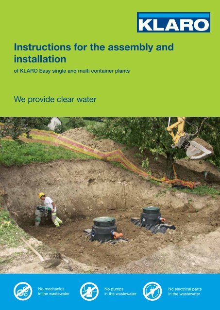
<strong>Instructions</strong> <strong>for</strong> <strong>the</strong> <strong>assembly</strong> <strong>and</strong><br />
<strong>installation</strong><br />
of <strong>KLARO</strong> Easy single <strong>and</strong> multi container plants<br />
We provide clear water<br />
No mechanics<br />
in <strong>the</strong> wastewater<br />
No pumps<br />
in <strong>the</strong> wastewater<br />
No electrical parts<br />
in <strong>the</strong> wastewater
No mechanics<br />
in <strong>the</strong> wastewater<br />
No pumps<br />
in <strong>the</strong> wastewater<br />
No electrical parts<br />
in <strong>the</strong> wastewater
<strong>Instructions</strong> <strong>for</strong> <strong>the</strong> <strong>assembly</strong> <strong>and</strong> <strong>installation</strong> of <strong>KLARO</strong> Easy<br />
<strong>Instructions</strong> <strong>for</strong> <strong>the</strong> <strong>assembly</strong> & <strong>installation</strong><br />
of <strong>KLARO</strong> Easy<br />
single <strong>and</strong> multi container plants<br />
<strong>KLARO</strong> <strong>GmbH</strong><br />
Spitzwegstrasse 63<br />
95447 Bayreuth<br />
Phone: (0921)16279-0<br />
Fax: (0921)16279-100<br />
info@klaro.eu<br />
www.klaro.eu<br />
<strong>KLARO</strong> <strong>GmbH</strong> 3
<strong>Instructions</strong> <strong>for</strong> <strong>the</strong> <strong>assembly</strong> <strong>and</strong> <strong>installation</strong> of <strong>KLARO</strong> Easy<br />
Table of contents<br />
Page<br />
1. General notes ...................................................................................................................................5<br />
1.1. Warranty...........................................................................................................................................5<br />
1.2. Safety ...............................................................................................................................................5<br />
2. Preparation........................................................................................................................................5<br />
2.1. Transport ..........................................................................................................................................5<br />
2.2. Checking <strong>the</strong> delivery.......................................................................................................................5<br />
2.3. Storage.............................................................................................................................................5<br />
2.4. Dimensions of <strong>the</strong> containers...........................................................................................................6<br />
2.4.1. Carat..........................................................................................................................................6<br />
2.4.2. Carat XL ....................................................................................................................................7<br />
2.5. Installation ground ............................................................................................................................7<br />
2.6. Excavation pit ...................................................................................................................................7<br />
2.7. Installation conditions .......................................................................................................................8<br />
2.7.1. Groundwater <strong>and</strong> cohesive (water-impermeable) ground ........................................................8<br />
2.7.2. Slope, embankment, etc. ..........................................................................................................9<br />
2.7.3. Installation next to / in areas which are driven on.....................................................................9<br />
3. Installation in <strong>the</strong> excavation pit...................................................................................................10<br />
3.1. Installation of <strong>the</strong> containers ..........................................................................................................10<br />
3.2. Refilling <strong>the</strong> excavation pit..............................................................................................................10<br />
4. Technical <strong>assembly</strong> .......................................................................................................................10<br />
4.1. Connection of pipes........................................................................................................................10<br />
4.1.1. Connection of containers ........................................................................................................10<br />
4.1.2. Inlet <strong>and</strong> outlet.........................................................................................................................10<br />
4.1.3. Empty conduit .........................................................................................................................11<br />
4.1.4. Forced ventilation....................................................................................................................11<br />
4.2. Assembly of <strong>the</strong> telescopic dome shaft..........................................................................................12<br />
4.2.1. Assembly of <strong>the</strong> tank dome.....................................................................................................12<br />
4.2.2. Assembly of <strong>the</strong> telescopic dome shaft...................................................................................12<br />
4.2.3. Accessible telescopic dome shaft ...........................................................................................12<br />
4.2.4. Telescopic dome shaft which can be driven on with a car......................................................13<br />
4.2.5. Telescopic dome shaft made of concrete <strong>and</strong> cast iron .........................................................13<br />
4.2.6. Assembly of <strong>the</strong> intermediate piece ........................................................................................13<br />
4.3. Air hoses.........................................................................................................................................14<br />
4.4. Filling with water.............................................................................................................................14<br />
5. Assembly of <strong>the</strong> control cabinet...................................................................................................15<br />
5.1. Installation in interior zones............................................................................................................15<br />
5.2. Installation in exterior zones...........................................................................................................16<br />
5.2.1. Location...................................................................................................................................16<br />
5.2.2. Electricity supply .....................................................................................................................16<br />
5.2.3. Assembly <strong>and</strong> <strong>installation</strong>........................................................................................................16<br />
5.3. Connection of air hoses..................................................................................................................16<br />
6. Commissioning ..............................................................................................................................18<br />
7. Return of <strong>the</strong> commissioning report ............................................................................................18<br />
4 <strong>KLARO</strong> <strong>GmbH</strong>
<strong>Instructions</strong> <strong>for</strong> <strong>the</strong> <strong>assembly</strong> <strong>and</strong> <strong>installation</strong> of <strong>KLARO</strong> Easy<br />
1. General notes<br />
1.1. Warranty<br />
The instructions contained in this manual must be observed at all times. Noncompliance shall<br />
invalidate any warranty claim.<br />
All components must be checked <strong>for</strong> damage prior to <strong>assembly</strong> or <strong>installation</strong>.<br />
Installation is to be carried out by a specialised company.<br />
1.2. Safety<br />
The relevant accident prevention regulations according to <strong>the</strong> German Employers' Liability<br />
Association Regulations [BGV] C22 must be observed carrying out all work. A second person must<br />
be available to safeguard persons inspecting containers from <strong>the</strong> inside.<br />
Fur<strong>the</strong>rmore, all relevant regulations <strong>and</strong> st<strong>and</strong>ards must be observed when carrying out <strong>installation</strong>,<br />
<strong>assembly</strong>, maintenance, repairs, etc. The applicable in<strong>for</strong>mation is provided in <strong>the</strong> corresponding<br />
chapters of this manual.<br />
Prior to <strong>the</strong> access into <strong>the</strong> container, all chambers must be emptied. Never access a<br />
container as long as any chamber remains filled!<br />
The entire plant or any individual parts of it must be installed by a suitably trained professional <strong>and</strong> in<br />
compliance with <strong>the</strong> enclosed manual.<br />
When carrying out any work on <strong>the</strong> plant or parts of it, <strong>the</strong> entire plant must be decommissioned <strong>and</strong><br />
secured against unauthorised switching back on.<br />
The container cover must always be closed, except when working in<br />
<strong>the</strong> container. O<strong>the</strong>rwise, <strong>the</strong>re is a very significant risk of an accident<br />
occurring. The rain cover mounted <strong>for</strong> delivery is only a transport<br />
packaging. It can nei<strong>the</strong>r be walked on nor is it childproof <strong>and</strong><br />
must be exchanged <strong>for</strong> a suitable cover at <strong>the</strong> time of delivery<br />
(telescopic dome shaft with appropriate cover)! Only use original<br />
<strong>KLARO</strong> covers or covers approved by <strong>KLARO</strong> <strong>GmbH</strong> in writing.<br />
<strong>KLARO</strong> offers a wide range of accessories which are compatible <strong>and</strong><br />
can be assembled to <strong>for</strong>m complete systems. The use of o<strong>the</strong>r<br />
accessories may impair <strong>the</strong> functionality of <strong>the</strong> plant <strong>and</strong> void all liability<br />
<strong>for</strong> any resulting damage.<br />
2. Preparation<br />
2.1. Transport<br />
Transport <strong>the</strong> containers may only carried out with suitable means of transportation. The containers<br />
must be secured against shifting <strong>and</strong> falling during transport. If <strong>the</strong> containers are secured with<br />
lashing straps during transport, it must be ensured that <strong>the</strong> containers remain undamaged. Never tie<br />
down or lift <strong>the</strong> containers with thin steel ropes or chains. Never apply carrying straps to protruding<br />
container or attachment parts.<br />
It is imperative to avoid mechanical stress to <strong>the</strong> containers due to impacts. Never roll or drag<br />
containers along <strong>the</strong> ground.<br />
2.2. Checking <strong>the</strong> delivery<br />
The customer must check all parts <strong>for</strong> completeness on <strong>the</strong> basis of <strong>the</strong> shipping note <strong>and</strong> <strong>for</strong><br />
possible transport damage immediately at <strong>the</strong> time of delivery. We will not acknowledge complaints<br />
made at a later date. Damaged parts may not be installed.<br />
2.3. Storage<br />
If interim storage is required, <strong>the</strong> containers must be stored on a suitable <strong>and</strong> level surface, free from<br />
pointed objects. During storage, damage due to environmental impacts or third persons must be<br />
avoided.<br />
The equipment cabinet must be stored in a dry location.<br />
<strong>KLARO</strong> <strong>GmbH</strong> 5
<strong>Instructions</strong> <strong>for</strong> <strong>the</strong> <strong>assembly</strong> <strong>and</strong> <strong>installation</strong> of <strong>KLARO</strong> Easy<br />
2.4. Dimensions of <strong>the</strong> containers<br />
2.4.1. Carat<br />
Alternative inlet<br />
at a higher point:<br />
Mini h E + 0.26m<br />
Maxi h E + 0.27m<br />
t inl<br />
t out<br />
DN 100 DN 100<br />
t total<br />
h E<br />
l<br />
w<br />
Container size 3,750 l 4,800 l 6,500 l<br />
Mini tank dome<br />
Inlet depth t inl [m] 0.65 - 0.85<br />
Outlet depth t out [m] 0.66 - 0.86<br />
Installation t total [m] 2.01 - 2.21 2.24 - 2.44 2.52 - 2.72<br />
depth<br />
Maxi tank dome<br />
Inlet depth t inl [m] 0.98 – 1.18<br />
Outlet depth t out [m] 0.99 – 1.19<br />
Installation t total [m] 2.34 – 2.54 2.57 – 2.77 2.85 – 3.05<br />
depth<br />
Inlet h E [m] 1.36 1.59 1.87<br />
Width w [m] 1.76 1.99 2.19<br />
Length l [m] 2.28 2.28 2.39<br />
Weight without set-up kit [kg] 150 185 220<br />
St<strong>and</strong>ard sizes with<br />
mini telescopic<br />
cover<br />
6 <strong>KLARO</strong> <strong>GmbH</strong>
<strong>Instructions</strong> <strong>for</strong> <strong>the</strong> <strong>assembly</strong> <strong>and</strong> <strong>installation</strong> of <strong>KLARO</strong> Easy<br />
2.4.2. Carat XL<br />
h<br />
l<br />
b<br />
h<br />
l<br />
b<br />
Container size 8,500 l 10,000 l<br />
Weight [kg] 380 456<br />
Height h [mm] 2085 2285<br />
Width w [mm] 2040 2240<br />
Length l [mm] 3500 3520<br />
All dimensions are subject to a tolerance of +/- 3%.<br />
2.5. Installation ground<br />
The following issues must be clarified prior to <strong>installation</strong>:<br />
• structural suitability of <strong>the</strong> ground according to DIN 18196<br />
• max. possible groundwater levels or seepage capacity of <strong>the</strong> soil<br />
• possible mechanical loads, e.g. traffic loads<br />
The local building authorities can provide you with <strong>the</strong> physical parameters of <strong>the</strong> ground.<br />
2.6. Excavation pit<br />
In order to ensure sufficient working space, <strong>the</strong> surface area of <strong>the</strong> excavation pit must exceed <strong>the</strong><br />
container dimensions by approx. 500 mm on each side; <strong>the</strong> distance to static structures must be at<br />
least 1,000 mm.<br />
Excavation pit <strong>and</strong> embankment must be excavated <strong>and</strong> secured by <strong>the</strong> customer in compliance with<br />
DIN 4124. The embankment angle must be specified taking into account <strong>the</strong> relevant st<strong>and</strong>ards,<br />
rules <strong>and</strong> regulations <strong>for</strong> occupational safety. The ground to be built on must be horizontal <strong>and</strong> even<br />
<strong>and</strong> its adequate load carrying capacity must be ensured.<br />
<strong>KLARO</strong> <strong>GmbH</strong> 7
<strong>Instructions</strong> <strong>for</strong> <strong>the</strong> <strong>assembly</strong> <strong>and</strong> <strong>installation</strong> of <strong>KLARO</strong> Easy<br />
The depth of <strong>the</strong> pit must be specified such that <strong>the</strong> maximum coverage above <strong>the</strong> container is not<br />
exceeded (see chapter 2.7). If <strong>the</strong> plant is to be used throughout <strong>the</strong> year, <strong>the</strong> container <strong>and</strong> all<br />
components which carry water must be installed in frost-protected areas. Frost-free depth is usually<br />
approx. 600 - 800 mm. Detailed in<strong>for</strong>mation can be obtained from your local authorities. The<br />
substructure consists of a layer of compressed round grain gravel (grain size 8/16 according to DIN<br />
4226-1, thickness approx. 150 – 200 mm).<br />
1 Soil<br />
2 Dome shaft with telescopic attachment<br />
3 Compressed substructure<br />
4 Shell (round grain gravel, max. grain<br />
size 8/16 according to DIN 4226-1)<br />
5 Cover layer<br />
6 Container<br />
7 Concrete layer <strong>for</strong> areas driven on<br />
with cars<br />
2.7. Installation conditions<br />
General in<strong>for</strong>mation:<br />
• Special <strong>installation</strong> provisions must be observed <strong>for</strong> groundwater <strong>and</strong> slopes (see chapter<br />
2.6).<br />
• St<strong>and</strong>ard models can be walked on. If cars can be driving over <strong>the</strong> plant, see chapter<br />
2.7.3. Containers with a volume of at least 3,750 l can be driven over with lorries of up to<br />
12 tons if <strong>the</strong> covering is rein<strong>for</strong>ced as specified in chapter 4.2.10.<br />
• Max. soil coverage over <strong>the</strong> tank shoulder is:<br />
Max. soil cover<br />
- With connecting piece <strong>and</strong> telescopic [m] 1.50<br />
shaft<br />
- Telescopic dome shaft maxi + cast iron [m] 1.05<br />
- With st<strong>and</strong>ard dome shaft [m] 0.95<br />
Min. soil coverage [m] 0.75<br />
Requirements include:<br />
o Installation only in accessible areas.<br />
o The container must not be installed in groundwater <strong>and</strong> artesian water.<br />
2.7.1. Groundwater <strong>and</strong> cohesive (water-impermeable) ground<br />
In cases where only occasional groundwater <strong>and</strong> cohesive <strong>and</strong> water-impermeable ground (e.g.<br />
clay) occurs, appropriate drainage <strong>for</strong> groundwater <strong>and</strong> seepage water must be provided to ensure<br />
that <strong>the</strong> maximum water level of <strong>the</strong> container in <strong>the</strong> groundwater never exceeds <strong>the</strong> values indicated<br />
in <strong>the</strong> table.<br />
If necessary, <strong>the</strong> drainage pipe must end in a<br />
vertically installed DN 300 pipe with inserted<br />
submersion pressure pump which pumps out <strong>the</strong><br />
excess water. The pump must be checked on a<br />
regular basis.<br />
If <strong>the</strong> containers are expected to immerse deeper,<br />
it is absolutely necessary to provide adequate<br />
drainage.<br />
Container [l] 3,750 4,800 6,500 8,500 10,000<br />
Max. immersion depth [m] 1.59 0.91 1.05<br />
Min. soil cover [m] 0.80 0.80 0.80<br />
8 <strong>KLARO</strong> <strong>GmbH</strong>
<strong>Instructions</strong> <strong>for</strong> <strong>the</strong> <strong>assembly</strong> <strong>and</strong> <strong>installation</strong> of <strong>KLARO</strong> Easy<br />
2.7.2. Slope, embankment, etc.<br />
If <strong>the</strong> container is to be installed in <strong>the</strong> direct vicinity (< 5 m) of a slope, mound of earth or<br />
embankment, a statically calculated supporting wall which supports earth pressure must be<br />
constructed. The wall must protrude <strong>the</strong> container dimensions by at least 50 cm in all<br />
directions with a minimum distance of 100 cm to <strong>the</strong> container.<br />
2.7.3. Installation next to / in areas which are driven on<br />
Coverage heights <strong>for</strong> cast iron telescopic dome shafts (class B) in areas which are driven on<br />
by cars (load of up to 3.5 t) (without groundwater <strong>and</strong> artesian water).<br />
Coverage heights <strong>for</strong> telescopic dome shafts made of concrete <strong>and</strong> cast iron (with class D<br />
covering – to be provided by <strong>the</strong> customer) in areas driven on by 12 t lorries (load of up to 12<br />
t) (without groundwater <strong>and</strong> artesian water).<br />
<strong>KLARO</strong> <strong>GmbH</strong> 9
<strong>Instructions</strong> <strong>for</strong> <strong>the</strong> <strong>assembly</strong> <strong>and</strong> <strong>installation</strong> of <strong>KLARO</strong> Easy<br />
3. Installation in <strong>the</strong> excavation pit<br />
3.1. Installation of <strong>the</strong> containers<br />
Prior to <strong>the</strong> <strong>installation</strong> of <strong>the</strong> containers, <strong>the</strong> <strong>installation</strong> depth must be checked once again, in<br />
particular with regard to inlet <strong>and</strong> outlet height. Containers must be placed <strong>and</strong> aligned in compliance<br />
with <strong>the</strong> applicable <strong>installation</strong> drawing. Special attention must be paid to <strong>the</strong> exact horizontal<br />
<strong>installation</strong> of <strong>the</strong> container.<br />
3.2. Refilling <strong>the</strong> excavation pit<br />
The container must be lowered into <strong>the</strong> prepared excavation pit using appropriate gear (also see<br />
chapter 2.1 <strong>and</strong> 2.3 - Transport <strong>and</strong> storage). Impacts on <strong>the</strong> sides of <strong>the</strong> pit must be avoided. In<br />
order to avoid de<strong>for</strong>mations, <strong>the</strong> container encasement must be filled with water (1/3 <strong>for</strong> Carat <strong>and</strong><br />
25 cm <strong>for</strong> Carat XL) prior to filling in <strong>the</strong> space around <strong>the</strong> container. Then <strong>the</strong> encasement (round<br />
grain gravel with a max. grain size of 8/16 according to DIN 4226-1) is filled layer by layer in steps of<br />
max. 30 cm <strong>for</strong> Carat <strong>and</strong> max. 40 cm <strong>for</strong> Carat XL <strong>and</strong> compressed. Each layer must be well<br />
compressed (h<strong>and</strong> stamper). Make sure not to damage <strong>the</strong> container when compressing <strong>the</strong><br />
encasement. Never use mechanical compression machines. The encasement must have a width of<br />
min. 50 cm. The pit must be quickly filled in with round grain gravel within one day. O<strong>the</strong>rwise, in <strong>the</strong><br />
event of heavy rain, <strong>the</strong>re is a risk of<br />
excessive loads due to backwater.<br />
Filling material:<br />
– The filling material must be well<br />
compressible, permeable, shearingresistant,<br />
frost-proof <strong>and</strong> free from<br />
pointed objects.<br />
– These requirements are <strong>for</strong> example<br />
met by round grain gravel (with max.<br />
grain size 8/16 according to DIN<br />
4226-1).<br />
2. 3/3<br />
– Excavated soil or s<strong>and</strong> is not<br />
suitable in most cases.<br />
1. 1/3<br />
– Topsoil, clay <strong>and</strong> o<strong>the</strong>r cohesive soil<br />
is not suitable as filling material.<br />
Transport covers on <strong>the</strong> container, if any,<br />
must be removed <strong>and</strong> disposed of in an environmentally friendly way.<br />
4. Technical <strong>assembly</strong><br />
4.1. Connection of pipes<br />
4.1.1. Connection of containers<br />
Two or more containers are connected via <strong>the</strong> moulded <strong>assembly</strong> surfaces at <strong>the</strong> bottom of <strong>the</strong><br />
container using connecting pieces <strong>and</strong> KG pipes to be welded. Make sure that <strong>the</strong> distance between<br />
<strong>the</strong> containers is min. 1,000 mm <strong>for</strong> <strong>installation</strong> in longitudinal direction <strong>and</strong> 1,300 mm <strong>for</strong> <strong>installation</strong><br />
beside each o<strong>the</strong>r.<br />
The required connections of <strong>the</strong> two containers are prepared at <strong>the</strong> factory.<br />
The PVC-KG DN 100 connections <strong>for</strong> sludge recirculation between <strong>the</strong> containers must be<br />
connected with each o<strong>the</strong>r. The KG pipes must protrude into <strong>the</strong> container by min. 20 cm.<br />
4.1.2. Inlet <strong>and</strong> outlet<br />
Inlet <strong>and</strong> outlet pipes (PVC-KG DN 100) must be connected according to <strong>the</strong> drawing. All inlet <strong>and</strong><br />
outlet pipes must be laid with an incline of at least 1% (subsequent laying of pipes must be taken into<br />
account). The pipes are connected to <strong>the</strong> pre-drilled holes at <strong>the</strong> dome shaft or at <strong>the</strong> containers.<br />
10 <strong>KLARO</strong> <strong>GmbH</strong>
<strong>Instructions</strong> <strong>for</strong> <strong>the</strong> <strong>assembly</strong> <strong>and</strong> <strong>installation</strong> of <strong>KLARO</strong> Easy<br />
4.1.3. Empty conduit<br />
An empty DN 100 conduit with internal<br />
taut wire must be laid with an inclination<br />
from <strong>the</strong> place where <strong>the</strong> equipment<br />
cabinet is installed to <strong>the</strong> SBR container.<br />
The empty conduit must be laid as<br />
straight as possible. Required pipe<br />
elbows must be made with shaped pieces<br />
with a maximum angle of 30°. The<br />
absolute maximum length of <strong>the</strong> empty<br />
conduit is 20 m. Please contact us in <strong>the</strong><br />
case of larger distances.<br />
The empty conduit must be sealed<br />
gas-tight at <strong>the</strong> control cabinet be<strong>for</strong>e<br />
completing <strong>the</strong> <strong>assembly</strong> work (see<br />
chapter 4.3)!<br />
>1%<br />
>1%<br />
>1%<br />
The following must be observed <strong>for</strong> <strong>the</strong> laying of <strong>the</strong> pipes:<br />
In areas 10 cm + 0.1 x DN below <strong>the</strong> pipe bottom of <strong>the</strong> pipe, <strong>the</strong> filled in material must be levelled<br />
out, while maintaining <strong>the</strong> indicated pipe inclination. A s<strong>and</strong> bed must be put in place on <strong>the</strong><br />
prepared ground, <strong>and</strong> <strong>the</strong> pipes must be embedded in <strong>the</strong> s<strong>and</strong> such that a support angle of at least<br />
90° is <strong>for</strong>med. The pipes must be precisely fixed in position, <strong>and</strong> <strong>the</strong>n approx. 30 cm of s<strong>and</strong> must be<br />
filled in. Laying, filling <strong>and</strong> compressing must be carried out in compliance with <strong>the</strong> laying instructions<br />
<strong>for</strong> PVC duct pipes.<br />
4.1.4. Forced ventilation<br />
According to DIN 4261-1, all chambers / containers must be ventilated. If<br />
necessary, additional ventilation pipes or ventilation openings must be<br />
provided. The ventilation pipes must be arranged in such a fashion that natural<br />
ventilation is possible (chimney effect). For this purpose, <strong>the</strong> supply line can be<br />
laid via <strong>the</strong> roof, or a DN 100 PVC KG pipe may be connected to a free<br />
opening at <strong>the</strong> dome shaft <strong>and</strong> laid with an inclination to <strong>the</strong> place of<br />
ventilation.<br />
<strong>KLARO</strong> <strong>GmbH</strong> 11
<strong>Instructions</strong> <strong>for</strong> <strong>the</strong> <strong>assembly</strong> <strong>and</strong> <strong>installation</strong> of <strong>KLARO</strong> Easy<br />
4.2. Assembly of <strong>the</strong> telescopic dome shaft<br />
4.2.1. Assembly of <strong>the</strong> tank dome<br />
Prior to <strong>the</strong> actual <strong>assembly</strong>, <strong>the</strong> supplied seal is inserted into <strong>the</strong> sealing groove of tank neck "B"<br />
between <strong>the</strong> tank <strong>and</strong> tank dome; <strong>the</strong>n <strong>the</strong> tank dome is aligned with <strong>the</strong> pipes <strong>and</strong> engaged with<br />
catch on <strong>the</strong> tank. After engaging <strong>the</strong> catch, no fur<strong>the</strong>r rotation is possible. Please pay attention to<br />
<strong>the</strong> correct positioning of <strong>the</strong> upper seal "A".<br />
4.2.2. Assembly of <strong>the</strong> telescopic dome shaft<br />
The telescopic dome shaft allows <strong>for</strong> <strong>the</strong> continuously<br />
variable adjustment of <strong>the</strong> container to a given ground<br />
level of between 750 mm <strong>and</strong> 950 mm (mini telescopic<br />
dome shaft) <strong>and</strong> 750mm <strong>and</strong> 1,050 mm (maxi<br />
telescopic dome shaft).<br />
In order to assemble, <strong>the</strong> supplied profile seal (EPDM<br />
material) is inserted into <strong>the</strong> sealing groove of <strong>the</strong> tank<br />
dome, <strong>and</strong> a generous amount of soft soap is applied<br />
(do not use lubricants on mineral oil basis because<br />
<strong>the</strong>se would corrode <strong>the</strong> seal). The telescope is <strong>the</strong>n<br />
also lubricated, inserted <strong>and</strong> aligned to <strong>the</strong> ground level.<br />
4.2.3. Accessible telescopic dome shaft<br />
Important: In order to prevent <strong>the</strong> transfer of loads to<br />
<strong>the</strong> container, <strong>the</strong> telescope is filled with layers of<br />
round grain gravel (max. grain size 8/16) <strong>and</strong> evenly<br />
compressed. Make sure not to damage <strong>the</strong> container<br />
tank dome <strong>and</strong> <strong>the</strong> telescope when doing so. Then<br />
<strong>the</strong> cover is applied <strong>and</strong> locked so as to be childproof,<br />
i.e. <strong>the</strong> screw connection at <strong>the</strong> cover must be<br />
tightened until it cannot be opened by a child!<br />
12 <strong>KLARO</strong> <strong>GmbH</strong>
<strong>Instructions</strong> <strong>for</strong> <strong>the</strong> <strong>assembly</strong> <strong>and</strong> <strong>installation</strong> of <strong>KLARO</strong> Easy<br />
4.2.4. Telescopic dome shaft which can be driven on with a car<br />
If <strong>the</strong> container is installed beneath areas which are<br />
driven on by cars, <strong>the</strong> telescope (anthracite colour)<br />
must be lined with concrete (load class B25 = 250<br />
kg/m²) in <strong>the</strong> neck section. The concrete layer to be<br />
filled in must have a circumferential width of min. 300<br />
mm <strong>and</strong> a height of approx. 200 mm. The min.<br />
coverage over <strong>the</strong> tank shoulder is 800 mm (max. 1,050<br />
mm with telescope, coverage of up to max. 120 mm<br />
with an intermediate piece is possible).<br />
Attention: Please always use <strong>the</strong> cast iron cover.<br />
4.2.5. Telescopic dome shaft made of concrete <strong>and</strong> cast iron<br />
For <strong>installation</strong>s beneath areas driven on by 12 t<br />
lorries, <strong>the</strong> telescope is lined as described in chapter<br />
6.2. Then, <strong>the</strong> concrete rings (Ø 600 mm) <strong>and</strong> a cast<br />
iron frame with star-like load distribution are installed<br />
to support <strong>the</strong> cast iron cover (soil coverage of min.<br />
800 mm, max. 1,200 mm must be adhered with). The<br />
cast iron frame must have a supporting surface of<br />
approx. 1m².<br />
4.2.6. Assembly of <strong>the</strong> intermediate piece<br />
Intermediate pieces which are required <strong>for</strong> major soil covers<br />
must be inserted into <strong>the</strong> tank dome using soft soap. The profile<br />
seal must be inserted into <strong>the</strong> top groove of <strong>the</strong> intermediate<br />
piece <strong>and</strong> well lubricated. Then <strong>the</strong> telescopic dome shaft must<br />
be inserted <strong>and</strong> adjusted to <strong>the</strong> planned ground surface of <strong>the</strong><br />
surrounding area.<br />
1 intermediate piece = max. soil coverage of 1,200 mm<br />
(each in connection with <strong>the</strong> maxi telescopic dome shaft)<br />
Telescopic dome shaft (can be tilted by 5°)<br />
Intermediate piece<br />
Tank dome (can be rotated by 360°)<br />
<strong>KLARO</strong> <strong>GmbH</strong> 13
<strong>Instructions</strong> <strong>for</strong> <strong>the</strong> <strong>assembly</strong> <strong>and</strong> <strong>installation</strong> of <strong>KLARO</strong> Easy<br />
4.3. Air hoses<br />
Four air hoses are required <strong>for</strong> <strong>the</strong> connection between <strong>the</strong> SBR container <strong>and</strong> machine cabinet. In<br />
order to avoid any possible mixing up of <strong>the</strong> hoses when connecting <strong>the</strong>m up, <strong>the</strong>y are supplied in<br />
different colours – corresponding to <strong>the</strong> coloured coding of <strong>the</strong> lifter in <strong>the</strong> container.<br />
Valve Colour Part Internal diameter of <strong>the</strong> hose<br />
1 Black Outlet lifter 13 mm (19 mm from 40 EW)<br />
2 Blue Ventilation 19 mm<br />
3 White Excess sludge lifter 13 mm (19 mm from 40 EW)<br />
4 Red Charging lifter 13 mm (19 mm from 40 EW)<br />
The distance between container <strong>and</strong> control cabinet should not exceed 20m. Please contact us in<br />
<strong>the</strong> case of larger distances.<br />
A bag with hose clips is present at <strong>the</strong> downpipe of <strong>the</strong> ventilation system. They must be used to<br />
connect <strong>the</strong> continuing air hoses to <strong>the</strong> corresponding grommets of <strong>the</strong> pre-mounted hoses at <strong>the</strong><br />
access opening of <strong>the</strong> SBR container.<br />
The red hose which is pre-mounted to <strong>the</strong> charging lifter must be laid through <strong>the</strong> return pipe from<br />
<strong>the</strong> sludge reservoir to <strong>the</strong> access opening of <strong>the</strong> SBR reactor.<br />
Finally, <strong>the</strong> four air hoses must be drawn through <strong>the</strong> empty conduit using a taut wire. Please make<br />
sure not to bend <strong>the</strong> air hoses.<br />
Charging<br />
air-lifter<br />
Pipe lead<br />
red hose<br />
Extrasludge<br />
Membrane disc<br />
Discharging<br />
air-lifter<br />
Inlet<br />
DN 100<br />
Outlet<br />
DN 100<br />
Red<br />
hose<br />
(Charging air-lifter)<br />
White<br />
hose<br />
(Extra-sludge<br />
air-lifter)<br />
Connected to<br />
manhole<br />
( Empty tube DN 100)<br />
Blue<br />
hose<br />
(Membrane<br />
disc)<br />
Black<br />
hose<br />
(Discharging<br />
air-lifter)<br />
Illustration 1:<br />
After <strong>the</strong> laying <strong>and</strong> connection of <strong>the</strong> hoses, <strong>the</strong> empty conduit must be sealed with a wall<br />
duct, or PU foam if no <strong>KLARO</strong> wall duct is used, in order that no gas exchange through this<br />
pipe is possible (ex protection, humidity, odours!).<br />
In order to obtain a gas-tight sealing of <strong>the</strong> empty conduit, <strong>the</strong> following procedure <strong>for</strong> <strong>the</strong><br />
sealing of <strong>the</strong> empty conduit must be adhered with:<br />
• Hose surface <strong>and</strong> pipe walls must be roughly cleaned with water <strong>and</strong> slightly wetted with<br />
water be<strong>for</strong>e foaming.<br />
• When applying PU foam, make sure that each hose is covered from all sides.<br />
• In order to allow <strong>for</strong> easy foam application <strong>and</strong> <strong>the</strong> correct casing of <strong>the</strong> hoses, <strong>the</strong>y must<br />
be slightly moved in longitudinal direction when applying <strong>the</strong> PU foam.<br />
4.4. Filling with water<br />
After having connected <strong>the</strong> air hoses, <strong>the</strong> containers must be filled with fresh water. The filling level<br />
in all chambers must be between <strong>the</strong> minimum water level (min. WL) <strong>and</strong> maximum water level<br />
(max. WL) see Illustration 2:<br />
14 <strong>KLARO</strong> <strong>GmbH</strong>
<strong>Instructions</strong> <strong>for</strong> <strong>the</strong> <strong>assembly</strong> <strong>and</strong> <strong>installation</strong> of <strong>KLARO</strong> Easy<br />
Sludge store / buffer<br />
4 air hoses in empty<br />
tube DN 100 to<br />
switch cabinet with a<br />
fall to <strong>the</strong> tank<br />
Sequence batch reactor<br />
Charging<br />
air-lifter<br />
Pipe lead<br />
red hose<br />
Discharging<br />
air-lifter<br />
Extra-sludge<br />
air-lifter<br />
Illustration 2:<br />
5. Assembly of <strong>the</strong> control cabinet<br />
5.1. Installation in interior zones<br />
The interior control cabinet (see Illustration 3:<br />
Internal cabinet LxWxD = 50 x 50 x 30 cm) is<br />
equipped with 4 suspension attachments. The<br />
two upper attachments have special<br />
boreholes to allow <strong>for</strong> easy suspension. The<br />
required screws <strong>and</strong> dowels are provided in<br />
<strong>the</strong> accessory box. The cabinet must be<br />
mounted at a dry <strong>and</strong> cool place with<br />
adequate fresh air supply.<br />
The connecting pieces <strong>for</strong> <strong>the</strong> air hoses to <strong>the</strong><br />
pit are provided at <strong>the</strong> left side of <strong>the</strong> cabinet.<br />
Three of <strong>the</strong>se pieces must be connected with<br />
<strong>the</strong> compressed air lifters <strong>and</strong> <strong>the</strong> o<strong>the</strong>r piece<br />
must be connected with <strong>the</strong> downpipe of <strong>the</strong><br />
ventilation. The highly <strong>the</strong>rmally <strong>and</strong><br />
mechanically resistant air hoses can be<br />
ordered at <strong>KLARO</strong> in every required length.<br />
Illustration 3:<br />
Internal cabinet LxWxD = 50 x 50 x 30 cm<br />
<strong>KLARO</strong> <strong>GmbH</strong> 15
<strong>Instructions</strong> <strong>for</strong> <strong>the</strong> <strong>assembly</strong> <strong>and</strong> <strong>installation</strong> of <strong>KLARO</strong> Easy<br />
5.2. Installation in exterior zones<br />
5.2.1. Location<br />
The location of <strong>the</strong> exterior cabinet must be a cool place<br />
with no direct solar radiation onto <strong>the</strong> cabinet during <strong>the</strong><br />
summer months. The best locations are <strong>the</strong> east or north<br />
sides of buildings. The rear side of <strong>the</strong> outer column <strong>and</strong><br />
<strong>the</strong> sides of <strong>the</strong> outer plastic cabinet must be installed with<br />
a clearance of at least 10 cm to allow <strong>for</strong> <strong>the</strong> easy<br />
replacement of <strong>the</strong> filter mat at <strong>the</strong> ventilation grids <strong>and</strong> <strong>for</strong><br />
adequate air circulation. The absolute maximum length of<br />
<strong>the</strong> air hoses is 20 meters.<br />
5.2.2. Electricity supply<br />
A top hat rail socket / junction box is provided in <strong>the</strong> control<br />
cabinet <strong>for</strong> electricity supply. The cable used <strong>for</strong> <strong>the</strong><br />
electricity supply is laid via <strong>the</strong> base into <strong>the</strong> cabinet where<br />
it is connected.<br />
5.2.3. Assembly <strong>and</strong> <strong>installation</strong><br />
The plastic column (Illustration 4: Outer plastic column)<br />
must be inserted in <strong>the</strong> soil up to <strong>the</strong> marking which is<br />
applied to <strong>the</strong> front side of <strong>the</strong> cabinet. To do this, a<br />
sufficiently deep excavation must be provided where <strong>the</strong><br />
empty conduit with air hoses must be inserted.<br />
The foundation base of <strong>the</strong> outer cabinet (Illustration 5:<br />
Outer plastic cabinet) must be assembled according to <strong>the</strong><br />
provided <strong>assembly</strong> instructions. Then <strong>the</strong> base must be<br />
inserted in <strong>the</strong> excavation to a depth of approx. 64 cm.<br />
For both outer cabinet types, <strong>the</strong> remaining empty space in<br />
<strong>the</strong> base must be filled with s<strong>and</strong> or fine gravel to ensure<br />
<strong>the</strong> safe, solid <strong>and</strong> vertical position of <strong>the</strong> column / cabinet<br />
in <strong>the</strong> soil.<br />
5.3. Connection of air hoses<br />
Illustration 4: Outer plastic column<br />
Entrenchdeep max 639 mm<br />
The ventilation system <strong>and</strong> all three compressed air lifters<br />
must be connected to <strong>the</strong> magnetic valve bank in <strong>the</strong><br />
control cabinet. The lifters require hoses with an internal<br />
diameter of 13 mm (19 mm from 40 EW), <strong>and</strong> <strong>for</strong> <strong>the</strong><br />
ventilation system, a 19 mm hose is required. Make sure<br />
that <strong>the</strong> hoses are connected to <strong>the</strong> corresponding<br />
grommets. In order to avoid confusion, <strong>the</strong> lifters <strong>and</strong> <strong>the</strong><br />
downpipe of <strong>the</strong> ventilation system in <strong>the</strong> container as well Illustration 5: Outer plastic cabinet<br />
as all four grommets have coloured markings applied to<br />
<strong>the</strong> control cabinet.<br />
As a rule, terminals with <strong>the</strong> same colour must be connected to each o<strong>the</strong>r <strong>and</strong> fixated with hose<br />
fittings. Hoses in <strong>the</strong> corresponding colours can be supplied.<br />
Charging lifter red<br />
Ventilation blue<br />
Outlet lifter black<br />
Excess sludge lifter white<br />
16 <strong>KLARO</strong> <strong>GmbH</strong>
<strong>Instructions</strong> <strong>for</strong> <strong>the</strong> <strong>assembly</strong> <strong>and</strong> <strong>installation</strong> of <strong>KLARO</strong> Easy<br />
1 Control<br />
2 Valve bank with 4 magnetic valves<br />
3 Air compressor<br />
4 Cabinet ventilation<br />
5 Phosphate precipitant pump (optional)<br />
6 UV connection (optional)<br />
7 GSM modem / LAN adapter (optional)<br />
Illustration 6: Lateral view on <strong>the</strong> interior control cabinet with four hose<br />
connections<br />
1 Maintenance switch<br />
2 Control<br />
3 Valve bank with 4 magnetic<br />
valves<br />
4 Air compressor<br />
5 Ventilation opening (cabinet<br />
ventilation <strong>for</strong> Becker<br />
compressor type)<br />
6 Socket / connecting box<br />
7 Phosphate precipitant pump<br />
(optional)<br />
8 Modem (optional)<br />
9 Socket (optional)<br />
Illustration 7: Interior view of A column<br />
Illustration 8: Interior view of A cabinet<br />
After <strong>the</strong> laying <strong>and</strong> connection of <strong>the</strong> hoses, <strong>the</strong> empty conduit must be sealed with a wall<br />
duct, or PU foam if no <strong>KLARO</strong> wall duct is used, in order that no gas exchange through this<br />
pipe is possible (ex protection, humidity, odours!).<br />
DN 100 empty conduit cover<br />
order no. 901418<br />
PU foam<br />
order no. 981875<br />
In order to obtain a gas-tight sealing of <strong>the</strong> empty conduit, <strong>the</strong> following procedure <strong>for</strong> <strong>the</strong><br />
sealing of <strong>the</strong> empty conduit must be adhered with:<br />
<strong>KLARO</strong> <strong>GmbH</strong> 17
<strong>Instructions</strong> <strong>for</strong> <strong>the</strong> <strong>assembly</strong> <strong>and</strong> <strong>installation</strong> of <strong>KLARO</strong> Easy<br />
• Hose surface <strong>and</strong> pipe walls must be roughly cleaned with water <strong>and</strong> slightly wetted with<br />
water be<strong>for</strong>e foaming.<br />
• When applying PU foam, make sure that each hose is covered from all sides.<br />
• In order to allow <strong>for</strong> easy foam application <strong>and</strong> <strong>the</strong> correct casing of <strong>the</strong> hoses, <strong>the</strong>y must be<br />
slightly moved in longitudinal direction when applying PU foam.<br />
6. Commissioning<br />
The <strong>installation</strong> instructions <strong>for</strong> <strong>the</strong> containers <strong>and</strong> <strong>the</strong> description in <strong>the</strong> operating manual must be<br />
adhered with when commissioning.<br />
The maintenance switch must be turned to "I". The series number <strong>and</strong> version number of <strong>the</strong><br />
program are displayed on <strong>the</strong> control <strong>for</strong> a few seconds be<strong>for</strong>e it switches to automatic mode. Then<br />
<strong>the</strong> warning message "Set date <strong>and</strong> time!" occurs. This message can be acknowledged by pressing<br />
<strong>the</strong> ESC key twice. If a second warning message "Temp. max" appears, you must check whe<strong>the</strong>r <strong>the</strong><br />
temperature sensor at <strong>the</strong> rear side of <strong>the</strong> device is correctly plugged in. Then <strong>the</strong> current operating<br />
mode of <strong>the</strong> system is displayed on <strong>the</strong> liquid crystal display. For <strong>the</strong> correct storage of operating<br />
hours <strong>and</strong> event messages, date <strong>and</strong> time must be set with <strong>the</strong> appropriate menu item. The system<br />
initially runs in <strong>the</strong> "cycle break" until <strong>the</strong> first cycle starting time has been reached.<br />
These are <strong>the</strong> cycle starting times preset in <strong>the</strong> factory:<br />
1:30 am; 7:30 am; 1:30 pm; 7:30 pm<br />
The correct function of <strong>the</strong> ventilation device as well as <strong>the</strong> lifter must be checked in manual mode.<br />
The appropriate procedure is described in detail in <strong>the</strong> system manual which is available in <strong>the</strong><br />
equipment cabinet. Bubble <strong>for</strong>mation during ventilation must be even <strong>and</strong> complete. The<br />
compressed air lifters only work if <strong>the</strong> container is adequately filled with water.<br />
7. Return of <strong>the</strong> commissioning report<br />
The commissioning report must be completely filled in.<br />
- The original copy of <strong>the</strong> commissioning report must be archived in <strong>the</strong> files of <strong>the</strong> operator.<br />
- The first copy must be returned to <strong>the</strong> following address:<br />
<strong>KLARO</strong> <strong>GmbH</strong>, Mrs Menn, Spitzwegstrasse 63, 95447 Bayreuth<br />
- The second copy is <strong>for</strong> <strong>the</strong> company installing <strong>the</strong> system.<br />
Attention: Warranty claims can only be processed if <strong>the</strong> commissioning report has been supplied to<br />
<strong>KLARO</strong> <strong>GmbH</strong>.<br />
Appendix:<br />
- Commissioning report<br />
<strong>KLARO</strong> <strong>GmbH</strong><br />
Spitzwegstrasse 63<br />
95447 Bayreuth<br />
Phone: 0921-16279-0<br />
Fax: 0921-16279-100<br />
info@klaro.eu<br />
www.klaro.eu<br />
Status 02 / 2013<br />
Subject to technical changes.<br />
18 <strong>KLARO</strong> <strong>GmbH</strong>
The <strong>KLARO</strong> principle<br />
Maximum operating reliability!<br />
No mechanics, pumps or<br />
electrical parts in <strong>the</strong> wastewater!<br />
All components are permanently connected to <strong>the</strong> filtering tank. All transportation<br />
processes are per<strong>for</strong>med by <strong>the</strong> air-lift pump. All electrical parts are located securely<br />
outside <strong>the</strong> tank in <strong>the</strong> switch cabinet.<br />
Our benefits<br />
••<br />
TÜV-tested switch cabinets (EPP,<br />
indoor switch cabinet, outdoor<br />
switch cabinet)<br />
••<br />
Almost all possible approvals<br />
••<br />
Extremely short delivery times<br />
thanks to optimised production<br />
••<br />
Legal threshold values undercut<br />
by up to 90%<br />
••<br />
98% treatment per<strong>for</strong>mance in 6<br />
hours<br />
••<br />
Certified underload detection<br />
••<br />
Fully-biological mode of operation<br />
••<br />
Quality products, with extremely<br />
high customer satisfaction levels<br />
••<br />
Minimal power consumption<br />
••<br />
All transportation processes per<strong>for</strong>med<br />
by air-lift pump<br />
••<br />
Treat water <strong>and</strong> introduce it back<br />
into <strong>the</strong> natural cycle<br />
••<br />
Only one tank required <strong>for</strong> systems<br />
of up to 20 PE (Personnel<br />
Equivalent)<br />
••<br />
Suitable <strong>for</strong> retrofitting to practically<br />
any tank shape<br />
••<br />
Retrofitting possible in single,<br />
twin, triple <strong>and</strong> multi-chamber pits<br />
••<br />
Installation possible in any type of<br />
tank, from plastic to fibreglass to<br />
concrete
<strong>KLARO</strong> <strong>GmbH</strong><br />
Spitzwegstraße 63<br />
95447 Bayreuth<br />
Telephone: +49 (0) 921 16279-0<br />
Fax: +49 (0) 921 16279-100<br />
E-Mail: info@klaro.eu<br />
More in<strong>for</strong>mation at<br />
www.klaro.eu<br />
Technical hotline<br />
+49 (0) 921 16279-330<br />
Photo copyright: <strong>KLARO</strong> <strong>GmbH</strong><br />
© <strong>KLARO</strong> <strong>GmbH</strong> Bayreuth 2013 / Art.-No. KKA 0031E-02-2013-engl