CSD & SHD Catalog PDF - Harmonic Drive LLC
CSD & SHD Catalog PDF - Harmonic Drive LLC
CSD & SHD Catalog PDF - Harmonic Drive LLC

Create successful ePaper yourself
Turn your PDF publications into a flip-book with our unique Google optimized e-Paper software.
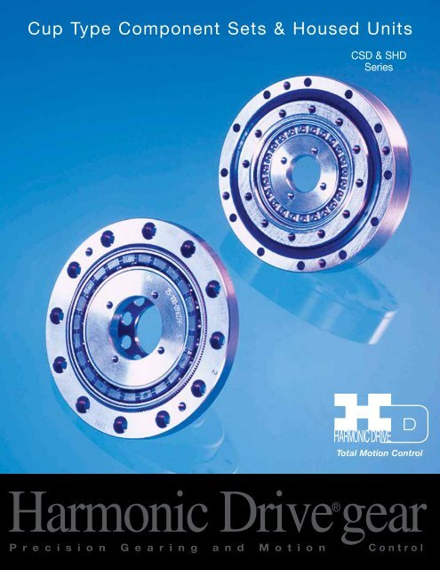
Cup Type Component Sets & Housed Units<br />
<strong>CSD</strong> & <strong>SHD</strong><br />
Series<br />
Total Motion Control<br />
<strong>Harmonic</strong> <strong>Drive</strong>®gear<br />
P r e c i s i o n G e a r i n g a n d M o t i o n Control
<strong>SHD</strong> Series<br />
2
Contents<br />
ABOUT HARMONIC DRIVE <strong>CSD</strong> & <strong>SHD</strong><br />
Ordering Information 4<br />
<strong>Harmonic</strong> <strong>Drive</strong> Gearing Mechanism Principle & Structure 5<br />
Driving Configurations 6<br />
Application Examples 7<br />
<strong>CSD</strong> Rating Table 8<br />
<strong>SHD</strong> Rating Table 9<br />
Technical Terms, Strength & Life 10<br />
Technical Terms, Life & Torque 11<br />
Selection Procedure & example 12<br />
<strong>Harmonic</strong> <strong>Drive</strong>® <strong>SHD</strong> Series Gear<br />
COMPONENT TYPE <strong>CSD</strong><br />
<strong>CSD</strong> External Dimension & Shape 14<br />
Lubrication 16<br />
Recommended Tolerances for Assembly 19<br />
Wave Generator Assembly Notes for <strong>CSD</strong> 20<br />
Assembly of the Flexspline 21<br />
Assembly of the Circular Spline, Assembly Notes 22<br />
<strong>CSD</strong> Assembly Procedure 23<br />
HOUSED UNIT TYPE <strong>SHD</strong><br />
<strong>SHD</strong> External Dimensions of Housed Unit 24<br />
Specifications for Cross Roller Bearing 26<br />
Output Bearing Calculations 27<br />
Output Bearing Life 28<br />
Lubrication 29<br />
Recommended Tolerances for Assembly 30<br />
<strong>SHD</strong> Assembly Notes and Procedure 35<br />
ENGINEERING DATA <strong>CSD</strong> & <strong>SHD</strong><br />
Efficiency of Component Set 36<br />
Efficiency of Housed Unit 37<br />
No Load Running Torque 38<br />
Starting Torque and Backdriving Torque 40<br />
Positioning Accuracy 41<br />
Torsional Stiffness 41<br />
Hysteresis Loss 43<br />
<strong>Harmonic</strong> <strong>Drive</strong> <strong>LLC</strong> 800-921-3332<br />
32
Ordering Information<br />
Ordering Code<br />
<strong>SHD</strong> Series<br />
Name of Model Size Ratio Model<br />
<strong>CSD</strong><br />
<strong>SHD</strong><br />
14 50, 100<br />
17 50, 100<br />
20 50, 100, 160 2A-GR: Component Type None: Standard<br />
25 50, 100, 160 (size 14 and 17<br />
32 50, 100, 160 are 2A-R)<br />
40 50, 100, 160 BB: Big Bore<br />
50 50, 100, 160 on Flexspline<br />
14 50, 100 (<strong>CSD</strong> Series)<br />
17 50, 100<br />
20 50, 100, 160 2SH<br />
25 50, 100, 160 Simplicity Unit Type SP: Special<br />
32 50, 100, 160<br />
40 50, 100, 160<br />
Evolution of <strong>Harmonic</strong> <strong>Drive</strong>® Gear Revolution<br />
<strong>Harmonic</strong> <strong>Drive</strong>® precision gear continues to evolve by improving performance and functionality.<br />
<strong>CSD</strong><br />
S Series<br />
CSF Series<br />
<strong>CSD</strong> & <strong>SHD</strong> Series<br />
By pursuing strength and<br />
The CSF achieved a<br />
stiffness, a new tooth profile<br />
reduction in axial length<br />
was invented. The “S” tooth of approximately 50% Achieve another axial<br />
doubled torque, life and stiffness<br />
length reduction of<br />
approximately 50%<br />
4
Principle and Structure<br />
Outer Cross<br />
Roller Bearing<br />
(Output)<br />
Flexspline<br />
Bolt<br />
(temporary)<br />
<strong>SHD</strong><br />
Circular Spline<br />
Wave Generator<br />
Wave Generator<br />
Flexspline<br />
<strong>CSD</strong><br />
<strong>SHD</strong> Series<br />
About <strong>Harmonic</strong> <strong>Drive</strong>® Gear<br />
Cross Roller Bearing<br />
Circular Spline<br />
Circular Spline<br />
Flexspline<br />
Wave Generator<br />
System Components<br />
The FLEXSPLINE is a non-rigid, steel cylindrical cup with external teeth on a slightly smaller pitch diameter than the Circular Spline.<br />
It fits over and is held in an elliptical shape by the Wave Generator.<br />
The WAVE GENERATOR is a thin raced ball bearing fitted onto an elliptical plug serving as a high efficiency torque converter.<br />
The CIRCULAR SPLINE is a rigid ring with internal teeth, engaging the teeth of the Flexspline across the major axis of the Wave Generator.<br />
0 º<br />
Circular Spline<br />
90º 360º<br />
Wave Generator<br />
Flexspline<br />
The Flexspline is elliptically shaped by The<br />
Wave Generator and engaged with the<br />
Circular Spline at the major elliptical axis.<br />
The teeth completely disengage on the<br />
minor axis.<br />
When the Circular Spline is fixed and<br />
the Wave Generator rotates clockwise,<br />
the Flexspline is elastically deformed<br />
and rotates counterclockwise relative to<br />
the Circular Spline.<br />
For each 360 degrees clockwise<br />
movement of the Wave Generator, the<br />
Flexspline moves counterclockwise by<br />
two teeth relative to the Circular Spline.<br />
5
Driving Configurations<br />
<strong>SHD</strong> Series<br />
About <strong>Harmonic</strong> <strong>Drive</strong>® Gear<br />
Driving Configurations<br />
A variety of different driving configurations<br />
are possible, as shown below.<br />
The reduction ratio R, given in the tables<br />
on page 7 and 8 correspond to<br />
arrangement 1, in which the<br />
Wave Generator acts as the<br />
input element, the Circular Spline<br />
is fixed and the Flexspline<br />
acts as the output element.<br />
Ratio =<br />
input speed<br />
output speed<br />
1. Reduction Gearing<br />
CS Fixed<br />
WG Input<br />
FS Output<br />
2. Reduction Gearing<br />
FS Fixed<br />
WG Input<br />
CS Output<br />
Ratio = —<br />
R<br />
1<br />
[Equation 1]<br />
Ratio =<br />
R + 1<br />
1<br />
[Equation 2]<br />
Input and output in opposite direction.<br />
Input and output in same direction.<br />
3. Reduction Gearing<br />
WG Fixed<br />
FS Input<br />
CS Output<br />
4. Speed Increaser Gearing<br />
WG Fixed<br />
CS Input<br />
FS Output<br />
5. Speed Increaser Gearing<br />
CS Fixed<br />
FS Input<br />
WG Output<br />
Ratio =<br />
R + 1<br />
R<br />
[Equation 3]<br />
Ratio =<br />
R<br />
R + 1<br />
[Equation 4]<br />
Ratio = —<br />
1<br />
R<br />
[Equation 5]<br />
Input and output in same direction.<br />
Input and output in same direction.<br />
Input and output in opposite direction.<br />
6. Speed Increaser Gearing<br />
FS Fixed<br />
CS Input<br />
WG Output<br />
Ratio =<br />
1<br />
R + 1<br />
[Equation 6]<br />
Input and output in same direction.<br />
7. Differential Gearing<br />
WG Control Input<br />
CS Main <strong>Drive</strong>-Input<br />
FS Main <strong>Drive</strong>-Output<br />
Numerous differential functions can<br />
be obtained by combinations of the<br />
speed and rotational direction of<br />
the three basic elements.<br />
6
Application Examples<br />
<strong>CSD</strong> Series<br />
Rotary Table for Machine Tool<br />
Flexspline<br />
<strong>SHD</strong> Series<br />
About <strong>Harmonic</strong> <strong>Drive</strong>® Gear<br />
Wave Generator<br />
Circular Spline<br />
<strong>SHD</strong> Series<br />
SCARA<br />
Simplicity Unit<br />
<strong>CSD</strong> • <strong>SHD</strong> Series<br />
2 Axis - Output Unit<br />
Circular Spline<br />
Flexspline<br />
Output 1<br />
Output 2<br />
Wave Generator<br />
Flexspline (<strong>SHD</strong>)<br />
<strong>Harmonic</strong> <strong>Drive</strong> <strong>LLC</strong> 800-921-3332<br />
7
<strong>CSD</strong> Rating Table<br />
About <strong>Harmonic</strong> <strong>Drive</strong>® Gear<br />
<strong>SHD</strong> Series<br />
<strong>CSD</strong> Gear Rated Limit for Limit for Limit for Maximum Limit for Moment<br />
Size Ratio Torque Repeated Average Momentary Input Average of<br />
at Peak Torque Peak Speed Input Inertia<br />
R 2000 Torque Torque Speed<br />
Tr<br />
rpm Nm Nm Nm rpm rpm I J<br />
Nm in-lb Nm in-lb Nm in-lb Nm in-lb Oil Grease Oil Grease x10 -4 kg•m 2 x10 -5 kgf•m•s 2<br />
14 50 3.7 33 12 106 4.8 42 24 212 14000 8500 6500 3500 0.021 0.021<br />
100 5.4 48 19 168 7.7 68 31 274<br />
Table 1<br />
17 50 11 97 23 204 18 159 48 425 10000 7300 6500 3500 0.054 0.055<br />
100 16 142 37 327 27 239 55 487<br />
50 17 150 39 345 24 212 69 611<br />
20 100 28 248 57 504 34 301 76* 673* 10000 6500 6500 3500 0.090 0.092<br />
(65) (575)<br />
160 28 248 64 566 34 301 76* 673*<br />
(65) (575)<br />
50 27 239 69 611 38 336 127 1124<br />
(135) (1195)<br />
25 100 47 416 110 974 75 664 152* 1345* 7500 5600 5600 3500 0.282 0.288<br />
(135) (1195)<br />
160 47 416 123 1089 75 664 152* 1345*<br />
50 53 469 151 1336 75 664 268 2372<br />
(331) (2929)<br />
32 100 96 850 233 2062 151 1336 359* 3177* 7000 4800 4600 3500 1.09 1.11<br />
(331) (2929)<br />
160 96 850 261 2310 151 1336 359* 3177*<br />
50 96 850 281 2487 137 1212 480 4248<br />
(580) (5133)<br />
40 100 185 1637 398 3522 260 2301 694* 6142* 5600 4000 3600 3000 2.85 2.91<br />
(580) (5133)<br />
160 206 1823 453 4009 316 2797 694* 6142*<br />
50 172 1522 500 4425 247 2186 1000 8850<br />
(1315) (11638)<br />
50 100 329 2912 686 6071 466 4124 1440 12744 4500 3500 3000 2500 8.61 8.78<br />
(1315) (11638)<br />
160 370 3275 823 7284 590 5222 1577* 13956*<br />
Note: The moment of inertia : I=1/4GD 2 , measured at the input<br />
The momentary peak torque is limited by tightening torque on the flexspline.<br />
The values in parenthesis are values in the case of the Big Bore option on the flexspline.<br />
8
<strong>SHD</strong> Rating Table<br />
<strong>SHD</strong> Ratio Rated Limit for Limit for Limit for Maximum Limit for Moment<br />
Size Torque Repeated Average Momentary Input Average of<br />
R at Peak Torque Peak Speed Input Inertia<br />
2000 Torque Torque Speed<br />
Tr<br />
rpm Nm Nm Nm rpm rpm I J<br />
Nm in-lb Nm in-lb Nm in-lb Nm in-lb Grease Grease x10 -4 kg•m 2 x10 -5 kgf•m•s 2<br />
14 50 3.7 33 12 106 4.8 42 23 204 8500 3500 0.021 0.021<br />
100 5.4 48 19 168 7.7 68 35 310<br />
17 50 11 97 23 204 18 159 48 425 7300 3500 0.054 0.055<br />
100 16 142 37 327 27 239 71 628<br />
50 17 150 39 345 24 212 69 611<br />
20 100 28 248 57 504 34 301 95 841 6500 3500 0.090 0.092<br />
160 28 248 64 566 34 301 95 841<br />
50 27 239 69 611 38 336 127 1124<br />
25 100 47 416 110 974 75 664 184 1628 5600 3500 0.282 0.288<br />
160 47 416 123 1089 75 664 204 1805<br />
50 53 469 151 1336 75 664 268 2372<br />
32 100 96 850 233 2062 151 1336 420 3717 4800 3500 1.09 1.11<br />
160 96 850 261 2310 151 1336 445 3938<br />
50 96 850 281 2487 137 1212 480 4248<br />
40 100 185 1637 398 3522 260 2301 700 6195 4000 3000 2.85 2.91<br />
160 206 1823 453 4009 316 2797 765 6770<br />
Table 2<br />
<strong>SHD</strong> Series<br />
About <strong>Harmonic</strong> <strong>Drive</strong>® Gear<br />
Note: The moment of inertia : I=1/4GD 2 , measured at the input.<br />
<strong>Harmonic</strong> <strong>Drive</strong> <strong>LLC</strong> 800-921-3332<br />
9
Technical Terms Strength & Life<br />
<strong>SHD</strong> Series<br />
About <strong>Harmonic</strong> <strong>Drive</strong>® Gear<br />
Definition of Ratings<br />
Rated Torque (Tr)<br />
Rated torque indicates allowable continuous load torque at<br />
2000 rpm input speed.<br />
Limit for Repeated Peak Torque (refer to figure 1)<br />
During acceleration a deceleration the <strong>Harmonic</strong> <strong>Drive</strong>® gear experiences<br />
a peak torque as a result of the moment of<br />
inertia of the output load. The table indicates the limit for<br />
repeated peak torque.<br />
Strength and Life<br />
The non-rigid Flexspline is subjected to repeated deflections, and its<br />
strength determines the torque capacity of the <strong>Harmonic</strong> <strong>Drive</strong>® gear.<br />
The values given for Rated Torque at Rated Speed and for the allowable<br />
Repeated Peak Torque are based on an infinite fatigue<br />
life for the Flexspline.<br />
The torque that occurs during a collision must be below the momentary<br />
peak torque (impact torque). The maximum number<br />
of occurrences is given by the equation below.<br />
[Equation 1]<br />
Limit for Average Torque<br />
In cases where load torque and input speed vary, it is necessary<br />
to calculate an average value of load torque. The table indicates<br />
the limit for average torque. The average torque calculated<br />
must not exceed this limit.<br />
Limit for Momentary Peak Torque (refer to figure 1)<br />
The gear may be subjected to momentary peak torques in the<br />
event of a collision or emergency stop. The magnitude and frequency<br />
of occurrence of such peak torques must be kept to a minimum and<br />
they should, under no circumstance, occur during normal operating<br />
cycle. The allowable number of occurrences of the momentary peak<br />
torque may be calculated by using equation 1. Also see section<br />
“strength and life”.<br />
1.0 X 10 4 n: Input speed before collision<br />
N = ____________<br />
2 X n X t t: Time interval during collision<br />
60<br />
Please note:<br />
If this number is exceeded, the Flexspline may experience<br />
a fatigue failure.<br />
Ratcheting phenomenon<br />
When excessive torque is applied while the gear is in motion, the<br />
teeth between the Circular Spline and Flexspline may not engage properly.<br />
This phenomenon is called ratcheting and the torque at which<br />
this occurs is called ratcheting torque. Ratcheting may cause the<br />
Flexspline to become non-concentric with the Circular Spline. (See<br />
figure 1 & 2 on page 12) Operating in this condition may result in<br />
shortened life and a Flexspline fatigue failure.<br />
Figure 1<br />
Abnormal Impact Tor que<br />
Figure 2<br />
Load Tor que<br />
Number of Rotations<br />
of Wave Generator<br />
Start<br />
Routine<br />
Stop<br />
Speed Cycle<br />
Start<br />
T ime<br />
Load Tor que<br />
R epeated Peak Tor que<br />
T ime<br />
Momentary Peak Tor que<br />
Circular Spline<br />
Flexspline<br />
This condition is called “dedoidal”.<br />
Maximum Input Speed, Limit for average input speed<br />
Do not exceed the allowable rating.<br />
Moment of Inertia<br />
The rating indicates the moment of inertia reflected to the<br />
wave generator (gear input).<br />
Note!<br />
When ratcheting occurs, the teeth mesh abnormally as shown above.<br />
Vibration and Flexspline damage may occur.<br />
Once ratcheting occurs, the teeth wear excessively and the<br />
ratcheting torque may be lowered.<br />
10
Life Technical Terms<br />
<strong>CSD</strong> Ratcheting Torque Table 3 Nm<br />
Size<br />
Ratio<br />
50 100 160<br />
14 88 84 –<br />
17 150 160 –<br />
20 220 260 220<br />
25 450 500 450<br />
32 980 1000 980<br />
40 1800 2100 1800<br />
50 3700 4100 3600<br />
Table 4 Buckling Torque Nm<br />
<strong>CSD</strong><br />
Size<br />
All Ratio<br />
14 190<br />
17 330<br />
20 560<br />
25 1000<br />
32 2200<br />
40 4300<br />
50 8000<br />
About <strong>Harmonic</strong> <strong>Drive</strong>® <strong>SHD</strong> Series Gear<br />
<strong>SHD</strong> Ratcheting Torque Table 5 Nm<br />
Size<br />
Ratio<br />
50 100 160<br />
14 88 84 –<br />
17 150 160 –<br />
20 220 260 220<br />
25 450 500 450<br />
32 980 1000 980<br />
40 1800 2100 1800<br />
Table 6 Buckling Torque Nm<br />
<strong>SHD</strong><br />
Size<br />
All Ratio<br />
14 130<br />
17 260<br />
20 470<br />
25 850<br />
32 1800<br />
40 3600<br />
The Life of a Wave Generator<br />
The normal life of a gear is determined by the life of the wave<br />
generator bearing. The life may be calculated by using the input<br />
speed and the output load torque.<br />
Rated Lifetime L n : ( n = 10 or 50) , hours<br />
L10 <strong>CSD</strong>,<strong>SHD</strong>: 7,000<br />
L50 <strong>CSD</strong>,<strong>SHD</strong>: 35,000<br />
Equation for the expected life of the wave generator under<br />
normal operating conditions is given by the equation below.<br />
[Equation 2]<br />
Lh = Ln • ( Tr ) 3 • ( Nr )<br />
Tav Nav<br />
Lh : Expected Life, hours<br />
Ln : Rated Lifetime at L10 or L50 , hours<br />
Tr : Rated Torque (Tables 1, 2, 3)<br />
Nr : Rated input speed (2000 rpm)<br />
Tav : Average load torque on output side (page 14)<br />
Nav : Average input speed (page 14<br />
Load Torque (Rated Torque = 1)<br />
17<br />
16<br />
10<br />
9<br />
8<br />
7<br />
6<br />
5<br />
Relative Torque Rating<br />
The chart below shows the various torque specifications<br />
relative to rated torque. Rated Torque has been<br />
normalized to 1 for comparison.<br />
Figure 3<br />
NON-OPERATING ZONE<br />
Fatique Strength of Flexspline<br />
Life of the Wave Generator(L10)<br />
Buckling Torque<br />
Racheting Torque<br />
4<br />
Momentary Peak Torque<br />
3<br />
Repeated Peak Torque<br />
2<br />
NORMAL<br />
Rated Torque<br />
1<br />
OPERATING ZONE<br />
0<br />
10 5<br />
10 6 10 7 10 8 10 9 10 10<br />
Total Number of Input Rotations<br />
<strong>Harmonic</strong> <strong>Drive</strong> <strong>LLC</strong> 800-921-3332<br />
11
Selection Procedure<br />
About <strong>Harmonic</strong> <strong>Drive</strong>® Gear<br />
<strong>SHD</strong> Series<br />
Size Selection<br />
Generally, the operating conditions consist of fluctuating torques<br />
and output speeds. Also, an unexpected impact output torque<br />
must be considered.<br />
The proper size can be determined by converting fluctuating load<br />
torque into average load torque and equivalent load torque. This<br />
procedure involves selecting the size based on load torque for component<br />
sets.<br />
This procedure does not consider the life of the output bearing for<br />
housed units. Determining the life of the output bearing for various<br />
axial, radial, and moment loads is outlined on page 25.<br />
Figure 4<br />
Flow Chart for selecting a size<br />
Please use the flowchart shown below for selecting a size.<br />
Operating conditions must not exceed the performance<br />
ratings as described on page 12.<br />
Calculation of the average output torque<br />
Tav = 3 n 1•t 1•|T1| 3 +n2•t 2•|T2| 3 + ... n n•t n•|Tn| 3<br />
n 1•t 1+n2•t 2+ ... n n t n<br />
Selection of tentative size under the<br />
condition shown below.<br />
Torque<br />
rpm<br />
t1<br />
n1<br />
T1<br />
Tn<br />
T2<br />
T4<br />
T3<br />
t2 t3 t4 tn<br />
n2<br />
n3<br />
nn<br />
Time<br />
Average Output Speed<br />
no av = n 1•t 1•n 2•t 2+... n nt n<br />
t 1+t2•t 2+ ... t n<br />
Determine Gear Ratio<br />
n i max < = R<br />
n o max<br />
n i max may be limited by the motor.<br />
Calculation of the average input speed<br />
n i av = n o av •R<br />
Calculation of maximum input speed<br />
n i max = n o max •R<br />
n 1 n 2 n n are an average value.<br />
n4<br />
Time<br />
NG<br />
n i av < = Limit for average speed<br />
n i max < = Limit for maximum speed<br />
Parameters<br />
Load Torque<br />
Tn (Nm)<br />
Time<br />
tn (sec)<br />
Output Speed<br />
nn (rpm)<br />
Normal Operating Pattern<br />
Acceleration T1,t1, n 1<br />
Regular Operation T2,t2, n 2<br />
Deceleration T3,t3, n 3<br />
Dwell T4,t4, n 4<br />
Maximum RPM<br />
Max output speed<br />
n o maximum<br />
Max input speed<br />
n i maximum<br />
Impact Torque<br />
Ratings<br />
Rated Torque<br />
Rated Speed<br />
Ts,ts, n s<br />
Tr<br />
nr =2000 rpm<br />
Consider a different size or change operating requirements<br />
NG<br />
NG<br />
NG<br />
NG<br />
OK<br />
Confirm if T 1 and T 3 are less than the<br />
repeated peak torque specification.<br />
OK<br />
Confirm if T s (impact torque) is less than<br />
the momentary peak torque specification.<br />
OK<br />
Calculate the allowable number of rotations<br />
during impact torque.<br />
Ns = 104 ••••••Ns < = 1.0X10 4<br />
2• n s•R •t s<br />
60<br />
OK<br />
Calculate wave generator life.<br />
)3•( Lh<br />
= Ln<br />
• ( Tr nr Tav n i av )<br />
Make sure that the calculated life is suitable<br />
for the application.<br />
OK<br />
Gear is suitable for torque and speed requirements<br />
Also consider output bearing, environment, etc.<br />
12
Selection Example<br />
Values of an each Load Torque Pattern<br />
Load Torque Tn (Nm) no max = 14 rpm<br />
Time tn (sec) ni max = 1800 rpm<br />
Output Speed<br />
nn (rpm)<br />
Normal Operating Pattern<br />
Acceleration T 1 = 400 Nm, t 1 = 0.3 sec, n 1 = 7 rpm T s = 500 N m, t s = 0.15 sec, n s = 14 rpm<br />
Regular Operation Stop T 2 = 320 Nm, t 2 = 3 sec, n 2 = 14 rpm<br />
Deceleration T 3 = 200 Nm, t 3 = 0.4 sec, n 3 = 7 rpm L 10 > 7000 hrs.<br />
Dwell T 4 = 0 Nm, t 4 = 0.2 sec, n 4 = 0 rpm Oil Lubrication<br />
<strong>SHD</strong> Series<br />
About <strong>Harmonic</strong> <strong>Drive</strong>® Gear<br />
Tav (Nm)<br />
Tav = 3 7rpm•0.3sec•|400Nm| 3 +14rpm•3sec•|320Nm| 3 +7rpm•0.4sec•|200Nm| 3<br />
7rpm•0.3sec+14rpm•3sec+7rpm•0.4sec<br />
Tav = 319Nm100<br />
14 rpm<br />
ni av = 12rpm•100=1200rpm<br />
no max ni max (rpm)<br />
ni max = 14rpm•100=1400rpm<br />
= 12 rpm<br />
ni av =1440rpm
<strong>CSD</strong> External Dimension & Shape<br />
<strong>SHD</strong><br />
<strong>CSD</strong> Series<br />
Series<br />
øZ3<br />
U-øV<br />
D<br />
E<br />
C<br />
F<br />
O<br />
øP<br />
2-N<br />
3<br />
15º<br />
L-øM<br />
øZ1<br />
øT<br />
øJ<br />
øK H6<br />
*1 1<br />
*2<br />
C0.5<br />
C0.3<br />
H<br />
*11<br />
C0.5<br />
øBH7<br />
øa<br />
øAh7<br />
øQ<br />
øR<br />
øa<br />
*44<br />
G<br />
G1<br />
A<br />
b<br />
c<br />
C0.4<br />
4-S<br />
øZ2<br />
Expanded G Section<br />
1. #14 and 17 are co.4.<br />
2. #40 and 50 are co.5.<br />
3. #14 is 30º, #17 is 22.5º.<br />
4. #14 ‐32 are co.3, #40 and #50 are co.5.<br />
1 2 3 1 2 1 3<br />
1 Ball Separator<br />
2 Wave Generator Bearing<br />
3 Wave Generator Plug<br />
Size: 14, 17 Size: 20, 25, 32, 40, 50<br />
Outside appearance varies depending on size.<br />
Size: 14, 17 Size: 20, 25, 32, 40, 50<br />
14
<strong>CSD</strong> External Dimension & Shape<br />
<strong>CSD</strong> Dimensions Table 7 unit: (mm)<br />
Size 14 17 20 25 32 40 50<br />
øA h7 50 0<br />
-0.025<br />
60 0<br />
-0.030<br />
70 0<br />
-0.030<br />
85 0<br />
-0.035<br />
110 0<br />
-0.035<br />
135 0<br />
-0.040<br />
170 0<br />
-0.040<br />
øBH7 11 +0.018 0 15 +0.018 0 20 +0.021 0 24 +0.021 0 32 +0.025 0 40 +0.025 0 50 +0.025 0<br />
C 11 12.5 14 17 22 27 33<br />
<strong>SHD</strong> <strong>CSD</strong> Series<br />
Minimum<br />
housing<br />
clearance<br />
D 6.5 +0.2<br />
0<br />
7.5 +0.2<br />
0<br />
8 +0.3<br />
0<br />
10 +0.3<br />
0<br />
13 +0.3<br />
0<br />
16 +0.3<br />
0<br />
19.5 +0.3<br />
0<br />
E 1.4 1.7 2 2 2.5 3 3.5<br />
F 4.5 5 6 7 9 11 13.5<br />
G1 0.3 0.3 0.3 0.4 0.5 0.6 0.8<br />
H 4 5 5.2 6.3 8.6 10.3 12.7<br />
øJ 23 27.2 32 40 52 64 80<br />
øK H6 11 +0.011<br />
0<br />
11 +0.011<br />
0<br />
16 +0.011<br />
0<br />
20 +0.013<br />
0<br />
30 +0.013<br />
0<br />
32 +0.016<br />
0<br />
44 +0.016<br />
0<br />
L 6 8 12 12 12 12 12<br />
øM 3.4 3.4 3.4 3.4 4.5 5.5 6.6<br />
N M3 M3 M3 M3 M4 M5 M6<br />
O _ _ 3.3 3.3 4.4 5.4 6.5<br />
øP _ _ 6.5 6.5 8 9.5 11<br />
øQ 44 54 62 75 100 120 150<br />
øR 17 21 26 30 40 50 60<br />
S M3 M3 M3 M3 M4 M5 M6<br />
øT 17 19.5 24 30 41 48 62<br />
U 9 8 9 9 11 10 11<br />
øV 3.4 4.5 4.5 5.5 6.6 9 11<br />
øZ 1<br />
0.2 0.2 0.2 0.2 0.25 0.25 0.3<br />
øZ 2<br />
0.25 0.25 0.2 0.2 0.25 0.25 0.3<br />
øZ 3<br />
0.2 0.25 0.25 0.25 0.3 0.5 0.5<br />
øa 38 45 53 66 86 106 133<br />
b 6.5 7.5 8 10 13 16 19.5<br />
c 1 1 1.5 1.5 2 2.5 3.5<br />
weight (kg) 0.06 0.10 0.13 0.24 0.51 0.92 1.9<br />
Weight<br />
Note: Standard dimension for size 14 and 17 is the maximum bore.<br />
Dimensions for BB Table 8 unit:mm<br />
Size 20 25 32 40 50<br />
ø KH6 20 +0.013<br />
0<br />
24 +0.013<br />
0<br />
32 +0.016<br />
0<br />
40 +0.016<br />
0<br />
50 +0.016<br />
0<br />
U 12 12 12 14 14<br />
ø V 3.4 4.5 5.5 6.6 9<br />
ø T 26 32 42 52 65<br />
ø Z3 0.2 0.25 0.25 0.3 0.5<br />
Note: Standard dimension for size 14 and 17 is the maximum bore.<br />
• Installed surface on Circular Spline is shown as A.<br />
Use this surface for installation in case.<br />
• Dimensions shown below may be modified as a special order.<br />
B: Dimension of Wave generator<br />
U and V: Dimension of Flexspline<br />
L and M: Dimension of Circular spline<br />
• Dimensions for C•D•G must meet the tolerance<br />
values shown above.<br />
• øa, b, c must exceed the values shown above due to<br />
deformation of the flexspline.<br />
<strong>Harmonic</strong> <strong>Drive</strong> <strong>LLC</strong> 800-921-3332<br />
15
Lubrication<br />
<strong>SHD</strong><br />
<strong>CSD</strong> Series<br />
Series<br />
Lubricant<br />
Grease lubricant is the standard for the <strong>CSD</strong> unit. The temperature range is shown below. (Exceptions are shown on page 17.)<br />
Lubricant<br />
Lubricant<br />
Grease <strong>Harmonic</strong> Grease SK-1A<br />
Grease SK-1A 0ºC~+40ºC<br />
Grease <strong>Harmonic</strong> Grease SK-2<br />
Grease SK-2 0ºC~+40ºC<br />
Grease <strong>Harmonic</strong> Grease 4B-No.2<br />
Grease 4B-No.2 -10ºC~+70ºC<br />
Oil Industrial gear oil #2(high pressure) ISO VG68<br />
Oil ISO VG68 0ºC~+40ºC<br />
<strong>Harmonic</strong> Grease SK-1A<br />
This grease is developed for a <strong>Harmonic</strong> <strong>Drive</strong>® gear and features good durability and efficiency.<br />
<strong>Harmonic</strong> Grease SK-2<br />
This grease is developed for a small size <strong>Harmonic</strong> <strong>Drive</strong>® gear and features smooth rotation of the Wave Generator<br />
since high pressure additive is liquefied.<br />
<strong>Harmonic</strong> Grease 4BNo.2<br />
This grease is developed for <strong>Harmonic</strong> <strong>Drive</strong>® gear and features long life and a wide range of temperature.<br />
Note 1<br />
Grease lubrication must have proper sealing, this is essential for 4B No.2.<br />
Rotating part: Oil seal with spring is needed.<br />
Mating part: O ring or seal adhesive is needed.<br />
Note 2<br />
The grease has the highest deterioration rate in the region where the grease is subjected to the greatest shear (near wave generator).<br />
Its viscosity is between JIS No.0 and No.00 depending on the operation.<br />
Recommended Grease<br />
Size 14 17 20 25 32 40 50<br />
SK-1A — — O O O O O<br />
SK-2 O O ∆ ∆ ∆ ∆ —<br />
4BNo.2 • • • • • • •<br />
• : recommended grease for long life and high load O: Standard ∆: Semistandard<br />
Characteristics of Grease<br />
Grease SK-1A SK-2 4BNo.2<br />
Durability O O •<br />
Fretting Resistance O O •<br />
Low Temp ∆ ∆ •<br />
Grease Leakage • • ∆<br />
• : Excellent O: Good ∆: Exercise Caution<br />
Recommended Grease<br />
Grease SK-1A SK-2 4B No.2<br />
Base Oil<br />
Thickening Agent<br />
Refined mineral hydrocarbon Refined mineral hydrocarbon Hydrocarbon type synthetic<br />
base oil base oil oil and polymer<br />
Lithium soap<br />
thickener<br />
Lithium soap<br />
thickener<br />
Additive Organic molybdenum, etc. Organic molybdenum, etc. Organic molybdenum, etc.s<br />
NLGI Consistency No. No.2 No.2 No.1.5<br />
Viscosity (25C) cSt 265 to 295 265 to 295 290 to 320<br />
Melting Point 197ºC 198ºC 247ºC<br />
Color Yellow Green Light Yellow<br />
Life<br />
5 Years in Airtight Container<br />
Urea<br />
16
Lubrication<br />
Recommended Dimensions for Inner Case<br />
Recommended dimensions for inner case must meet with<br />
numbers shown below. These dimensions must be maintained to prevent<br />
damage to the gear and to maintain a proper grease cavity.<br />
<strong>SHD</strong> <strong>CSD</strong> Series<br />
Figure 4<br />
Recommended Dimensions for Inner Case Table 9 Unit: mm<br />
Size 14 17 20 25 32 40 50<br />
ø a 38 45 53 66 86 106 133<br />
b 6.5 7.5 8 10 13 16 19.5<br />
c 1(3) 1(3) 1.5(4.5) 1.5(4.5) 2(6) 2.5(7.5) 3.5<br />
ød +0.5<br />
0<br />
16 26 30 37 37 45 45<br />
Note: Values in parenthesis show the value when the Wave Generator is pointing up.<br />
Figure 5<br />
CIRCULAR SPLINE FLEXSPLINE WAVE GENERATOR<br />
Apply thin coat<br />
to avoid corrosion<br />
Fill the toothbed<br />
with grease<br />
Apply thin coating<br />
of grease before<br />
installation<br />
Fill the<br />
toothbed<br />
with grease<br />
Apply grease to<br />
inner surface<br />
in accordance<br />
with a value<br />
shown above.<br />
Fill cavity<br />
between<br />
retainer and<br />
bearing<br />
with grease.<br />
Grease Usage Table 10 Unit: g<br />
Size 14 17 20 25 32 40 50<br />
amount 3.5 5.2 9.0 17 37 68 131<br />
<strong>Harmonic</strong> <strong>Drive</strong> <strong>LLC</strong> 800-921-3332<br />
17
Lubrication<br />
<strong>SHD</strong><br />
<strong>CSD</strong> Series<br />
Series<br />
Grease Change<br />
The wear characteristics of the gear is strongly influenced by the<br />
condition of the grease lubrication. The condition of the grease is<br />
affected by the ambient temperature. The graph shows the maximum<br />
number of input rotations for various temperatures. This graph applies<br />
to applications where the average load torque does not exceed the<br />
rated torque.<br />
In cases where the average load torque exceeds rated torque, calculate<br />
the grease change interval using the equation shown below.<br />
Equation where average load torque exceeds rated torque<br />
[Equation [3]<br />
Symbol of Equation [2]<br />
L GT = L GTn X ( Tr ) 3<br />
Tav<br />
LGT n, Total Number of Rotations of Wave Generator<br />
10 10<br />
10 9<br />
10 8<br />
Graph of LGTn vs. Temperature<br />
Grease Life<br />
4B No.2<br />
SK-1A<br />
SK-2<br />
Wave Generator Life<br />
L GT<br />
L GTn<br />
T r<br />
Grease change (average torque is over rated torque), input rotations<br />
Grease change (average torque is below rated torque), input rotations (From Graph)<br />
Rated Torque<br />
10 7 20 40 60 80 100 120<br />
Grease Temperature (ºC)<br />
T av Average load torque on output<br />
Figure 6<br />
Oil Temperature<br />
In normal use, the oil temperature must not exceed 90ºC,<br />
Above this temperature oil quickly loses its lubricating capabilities.<br />
Other notes: Avoid mixing different kinds of oil. The gear should be in<br />
an individual case when installed.<br />
Oil Change<br />
The first oil change should be performed after 100 hours of operation.<br />
The need to perform subsequent oil changes will depend on operating<br />
conditions, but should take place at intervals of approximately<br />
1000 running hours.<br />
High Temperature Lubricants<br />
<strong>Harmonic</strong> Grease 4B No.2<br />
Type of lubricant Standard temperature range Possible temperature range<br />
grease –10ºC~+110ºC –50ºC~+130ºC<br />
Low Temperature Lubricant<br />
Type of lubricant Name of lubricant and manufacturer Possible temperature range<br />
Grease Multemp SH-K2 Kyodo Yushi –30ºC~+50ºC<br />
Iso Flex LDS-18 special A NOK kluber<br />
–25ºC~+80ºC<br />
High Temperature Lubricant<br />
Type of lubricant Name of lubricant and manufacturer Possible temperature range<br />
Oil SH-200-100CS Tore Silicon –10ºC~+110ºC<br />
Shintesso D-32EP NOK kluber<br />
–25ºC~+90ºC<br />
grease Mobil Grease 28 –5ºC~+160ºC<br />
oil Mobil SHC-626 –5ºC~+140ºC<br />
Standard temperature is the grease temperature during operation.<br />
It is not the ambient temperature.<br />
The temperature range of the grease can be extended as indicated in<br />
the possible temperature range shown. At the low end of this range<br />
the efficiency will be low due to an increase in viscosity of the lubricant.<br />
At the high end of this range the lubricant life will be low due to<br />
an increased deterioration rate from the high temperature.<br />
18
Tolerance Assembly Notes<br />
Recommended Tolerances for Assembly<br />
Casefit Surface<br />
d A<br />
<strong>SHD</strong> <strong>CSD</strong> Series<br />
Circular Spline<br />
a A<br />
Installation Surface<br />
A<br />
B<br />
Casefit Surface<br />
e B<br />
Recommended<br />
Tolerance H7<br />
Recommended<br />
Tolerance H7<br />
Wave Generator<br />
f B<br />
Installation Surface<br />
Recommended<br />
øc A<br />
Shaft Tolerance h6<br />
Recommended<br />
øg B<br />
Shaft Tolerance h6<br />
b A<br />
Flexspline Installation Surface<br />
Tolerance for Assembly Table 11 unit:mm<br />
Size 14 17 20 25 32 40 50<br />
a 0.011 0.012 0.013 0.014 0.016 0.016 0.018<br />
b 0.008 0.011 0.014 0.018 0.022 0.025 0.030<br />
ø c 0.015 0.018 0.019 0.022 0.022 0.024 0.030<br />
d 0.011 0.015 0.017 0.024 0.026 0.026 0.028<br />
e 0.011 0.015 0.017 0.024 0.026 0.026 0.028<br />
f 0.008 0.010 0.010 0.012 0.012 0.012 0.015<br />
ø g 0.016 0.018 0.019 0.022 0.022 0.024 0.030<br />
Sealing structure<br />
A seal structure is needed to maintain the high durability of the gear and prevent grease leakage.<br />
Key Points to Verify<br />
• Rotating parts should have an oil seal (with spring), surface should be smooth (no scratches)<br />
• Mating flanges should have an O Ring, seal adhesive<br />
• Screws should have a thread lock<br />
(Loctite 242 recommended) or seal adhesive.<br />
Note: If you use <strong>Harmonic</strong> Grease 4BNo.2, strict sealing is required.<br />
<strong>Harmonic</strong> <strong>Drive</strong> <strong>LLC</strong> 800-921-3332<br />
19
Wave Generator Assembly Notes for <strong>CSD</strong><br />
<strong>SHD</strong><br />
<strong>CSD</strong> Series<br />
Series<br />
Direction for Thrust Force of Wave Generator<br />
<strong>CSD</strong><br />
F<br />
direction for thrust<br />
force in acceleration<br />
F<br />
direction for thrust<br />
force in deceleration<br />
Axial Force of Wave Generator<br />
When a <strong>CSD</strong> gear is used to accelerate a load, the deflection of the<br />
Flexspline leads to an axial force acting on the Wave Generator. This axial<br />
force, which acts in the direction of the closed end of the Flexspline, must be<br />
supported by the bearings of the input shaft (motor shaft).<br />
When a <strong>CSD</strong> gear is used to decelerate a load, an axial force acts to push<br />
the Wave Generator out of the Flexspline cup. Maximum axial force of the<br />
Wave Generator can be calculated by the equation shown below.<br />
The axial force may vary depending on its operating condition. The value of<br />
axial force tends to be a larger number when using high torque, extreme low<br />
speed and constant operation. The force is calculated (approximately) by<br />
the equation. In all cases, the Wave Generator must be axially (in both directions),<br />
as well as torsionally, fixed to the input shaft.<br />
Note: Please contact us for further information on attaching the Wave<br />
Generator to the input (motor) shaft.<br />
Figure 7<br />
Equation [4] for axial force<br />
Gear Ratio<br />
i=1/50<br />
i=1/100 and up<br />
equation<br />
F=2x T x 0.07 x tan 30º+2µPF<br />
D<br />
F=2x T x 0.07 x tan 20º+2µPF<br />
D<br />
Calculation Example<br />
size : 32<br />
Ratio : i=1/50<br />
Output Torque : 200Nm<br />
Table 12<br />
Thrust Force by Bearing<br />
Size 2µPF (Nm)<br />
14 2.1<br />
17 4.1<br />
<strong>CSD</strong> 20 5.6<br />
Symbols for equation [4]<br />
F thrust force N<br />
D Gear Size x 0.00254 m<br />
T output torque Nm<br />
2µPF thrust force by bearing Nm (see table)<br />
F=2x 200 x 0.07xtan 30º+16<br />
(32x0.00254)<br />
F=215N<br />
25 9.8<br />
32 16<br />
40 24<br />
50 39<br />
20
Flexspline Assembly Holes and Bolts<br />
Boss diameter of Flexspline Table 13<br />
Size 14 17 20 25 32 40 50<br />
Diaphragm<br />
Avoid<br />
<strong>SHD</strong> <strong>CSD</strong> Series<br />
øJ 23 27.2 32 40 52 64 80<br />
Head of bolt, nut and washer should not<br />
exceed the diameter of J<br />
Number of Holes and Location (Standard)<br />
Figure 8<br />
Number of Holes: 8 Number of Holes: 9 Number of Holes: 10 Number of Holes: 11<br />
<strong>CSD</strong>-17 <strong>CSD</strong>-14, 20, 25 <strong>CSD</strong>-40 <strong>CSD</strong>-32, 50<br />
Number of Holes and Location (Big Bore Option)<br />
Number of Holes: 12 Number of Holes: 14<br />
<strong>CSD</strong>-20.25 <strong>CSD</strong>-32, 40, 50<br />
Flexspline Bolts Table 14 Standard Big Bore Option<br />
Size 14 17 20 25 32 40 50 BB 20 BB 25 BB 32 BB 40 BB 50<br />
Number of Bolts 9 8 9 9 11 10 11 12 12 14 14 14<br />
Size M3 M4 M4 M5 M6 M8 M10 M3 M4 M5 M6 M8<br />
Pitch Circle Diameter mm 17 19.5 24 30 41 48 62 26 32 42 52 65<br />
Clamp<br />
Torque<br />
N•m 2.0 4.5 4.5 9.0 15.3 37 74 2 4.5 9.0 15.3 37<br />
Note:<br />
Torque N•m 32 55 76 152 359 694 1577 65 135 331 580 1315<br />
transmission<br />
1. The material of the thread must withstand the clamp torque.<br />
2. Recommended bolt : JIS B 1176 socket head cap screw strength range : JIS B 1051 over 12.9<br />
3. Torque coefficient : K=0.2<br />
4. Clamp coefficient A=1.4<br />
5. Friction coefficient on the surface contacted: 0.15<br />
6. Momentary peak torque is limited in Big Bore since bolt torque transmission of Big Bore is smaller than standard.<br />
<strong>Harmonic</strong> <strong>Drive</strong> <strong>LLC</strong> 800-921-3332<br />
21
Circular Spline Assembly Installation<br />
<strong>SHD</strong><br />
<strong>CSD</strong> Series<br />
Series<br />
Circular Spline Bolt Installation Table 15<br />
Size Standard 14 17 20 25 32 40 50<br />
Number of Bolts 6 8 12 12 12 12 12<br />
Size M3 M3 M3 M3 M4 M5 M6<br />
Pitch Circle Diameter mm 44 54 62 75 100 120 150<br />
Clamp Torque Nm 2.0 2.0 2.0 2.0 4.5 9.0 15.3<br />
Torque transmission Nm 55 90 155 188 422 810 1434<br />
Note:<br />
1. The material of the thread must withstand the clamp torque.<br />
2. Recommended bolt: JIS B 1176 socket head cap screw strength range : JIS B 1051 over 12.9.<br />
3. Torque coefficient : K=0.2<br />
4. Clamp coefficient A=1.4<br />
5. Friction coefficient on the surface contacted : 0.15<br />
Component Assembly Procedure<br />
When flexspline and<br />
wave generator are<br />
assembled, open part<br />
of flexspline will expand<br />
at major axis.<br />
flexspline<br />
wave generator<br />
circular spline<br />
Please see the following notes.<br />
22
<strong>CSD</strong> Assembly Procedure<br />
<strong>CSD</strong> assembly procedure<br />
Note for assembly structure for <strong>CSD</strong><br />
Flexspline<br />
1. Be sure flatness and skewness are minimized.<br />
<strong>SHD</strong> <strong>CSD</strong> Series<br />
Wave Generator<br />
1. Avoid overloading the Wave Generator bearing during<br />
installation, rotate the Wave Generator as you easily install.<br />
2. Since the Wave Generator of the <strong>CSD</strong> does not have an<br />
Oldham coupling, make sure that the position is within the<br />
recommended tolerance shown on page18.<br />
3. Installation bolts on Wave Generator and installation bolt on<br />
Flexspline should not interfere each other.<br />
Circular Spline<br />
1. Be sure flatness and skewness are minimized.<br />
2. Make sure there are no burrs or foreign substances.<br />
3. Make sure there is enough room to have the<br />
minimum clearance in the housing.<br />
4. Make sure that the Circular Spline can rotate in the housing<br />
when it is installed<br />
5. When a bolt is inserted into a bolt hole,<br />
make sure that the bolt hole is located properly.<br />
7. Bolts should not be tightened at the same time. Apply half<br />
of the recommended torque to tighten bolts, and then<br />
tighten bolts at the recommended torque. The order of<br />
tightening bolts should be done diagonally.<br />
Avoid using pins to secure the Circular Spline if possible.<br />
2. Make sure there are no burrs or foreign substances.<br />
3. Make sure there is enough room to have the minimum<br />
clearance in the housing.<br />
4. When a bolt is inserted into a bolt hole, make sure<br />
that the bolt hole is located properly.<br />
5. Bolts should not be tightened at the same time. Apply<br />
half of the recommended torque to tighten bolts, and then<br />
tighten bolts at recommended torque. The order of<br />
tightening bolts should be done diagonally.<br />
Make sure that Circular Spline and Flexspline mesh properly.<br />
Do not damage the Flexspline during assembly.<br />
Note to prevent corrosion<br />
The standard <strong>CSD</strong> has not been treated for preventing<br />
corrosion. If needed, apply rust prevention on metal<br />
surfaces. As a special order, <strong>Harmonic</strong> <strong>Drive</strong> <strong>LLC</strong> can<br />
provide stainless steel components or surface treatments.<br />
<strong>Harmonic</strong> <strong>Drive</strong> <strong>LLC</strong> 800-921-3332<br />
23
<strong>SHD</strong> External Dimensions<br />
<strong>SHD</strong><br />
<strong>SHD</strong> Series<br />
Series<br />
øN<br />
L-øM equally spaced<br />
F<br />
f (O Ring provided)<br />
D<br />
E1<br />
E2<br />
h Usable length<br />
g(seal)<br />
e (O Ring provided)<br />
equally spaced<br />
R1-R2<br />
øS<br />
U1-U2 depth V<br />
equally spaced<br />
øW<br />
øO<br />
Z2<br />
d<br />
H<br />
B2<br />
øT<br />
øJ h7<br />
øZ1<br />
øK H7<br />
øc<br />
X1<br />
I<br />
G<br />
øC H7<br />
øa<br />
øB1<br />
øA h6<br />
øQ<br />
C0.3<br />
P4<br />
P1-P2 length P3<br />
Do not remove<br />
these screws.<br />
X2<br />
Y<br />
b<br />
R Y3<br />
Y2 min.<br />
Y1 min.<br />
detailed drawings for Y<br />
Detailed drawings are also available<br />
1 2 3 1 2 1 3<br />
1 Ball Separator<br />
2 Wave Generator Bearing<br />
Size: 14, 17 Size: 20, 25, 32, 40<br />
3 Wave Generator Plug<br />
Size: 14, 17 Size: 20, 25, 32, 40<br />
24 24
<strong>SHD</strong> External Dimensions<br />
<strong>SHD</strong> Dimensions Table 16<br />
14 17 20 25 32 40<br />
øA h6 49 0<br />
-0.016<br />
59 0<br />
-0.019<br />
69 0<br />
-0.019<br />
84 0<br />
-0.022<br />
110 0<br />
-0.022<br />
132 0<br />
-0.025<br />
øB 1<br />
39.1 +0.1<br />
0<br />
48 +0.1<br />
0<br />
56.8 +0.1<br />
0<br />
70.5 +0.1<br />
0<br />
92 +0.1<br />
0<br />
112.4 +0.1<br />
0<br />
(mm)<br />
<strong>SHD</strong> Series<br />
minimum<br />
housing<br />
clearance<br />
B 2<br />
0.8 +0.15 0 1.1 +0.25 0 1.4 +0.25 0 1.7 +0.25 0 2 +0.25 0 2.2 +0.25 0<br />
øCH7 11 +0.018 0 15 +0.018 0 20 +0.021 0 24 +0.021 0 32 +0.025 0 40 +0.025 0<br />
D 17.5 ±0.1 18.5 ±0.1 19 ±0.1 22 ±0.1 27.9 ±0.1 33 ±0.1<br />
E 1<br />
15.5 16.5 17 20 23.6 28<br />
E 2<br />
2 2 2 2 4.3 5<br />
F 2.4 3 3 3.3 3.6 4<br />
G 1.8 1.6 1.2 0.4 0.6 0.8<br />
H 4 0<br />
- 0.1<br />
5 0<br />
- 0.1<br />
5.2 0<br />
- 0.1<br />
6.35 0<br />
- 0.1<br />
8.6 0<br />
- 0.1<br />
10.3 0<br />
- 0.1<br />
I 15.7 0<br />
- 0.2<br />
16.9 0<br />
- 0.2<br />
17.8 0<br />
- 0.2<br />
21.6 0<br />
- 0.2<br />
27.3 0<br />
- 0.2<br />
32.2 0<br />
- 0.2<br />
øJh7 70 0<br />
-0.030<br />
80 0<br />
-0.030<br />
90 0<br />
-0.035<br />
110 0<br />
-0.035<br />
142 0<br />
-0.040<br />
170 0<br />
-0.040<br />
øKH7 50 +0.025 0 61 +0.030 0 71 +0.030 0 88 +0.035 0 114 +0.035 0 140 +0.040 0<br />
L 8 12 12 12 12 12<br />
øM 3.5 3.5 3.5 4.5 5.5 6.6<br />
øN 0.25 0.25 0.25 0.25 0.25 0.3<br />
øO 64 74 84 102 132 158<br />
P 1<br />
2 2 2 4 4 4<br />
P 2<br />
M3 M3 M3 M3 M4 M4<br />
P 3<br />
6 6 6 8 10 10<br />
P 4<br />
22.5º 15º 15º 15º 15º 15º<br />
øQ 17 21 26 30 40 50<br />
R 1<br />
4 4 4 4 4 4<br />
R 2<br />
M3 M3 M3 M3 M4 M5<br />
øS 0.25 0.25 0.25 0.25 0.25 0.25<br />
øT 43 52 61.4 76 99 120<br />
U 1<br />
8 12 12 12 12 12<br />
U 2<br />
M3 M3 M3 M4 M5 M6<br />
V 4.5 4.5 4.5 6 8 9<br />
øW 0.25 0.25 0.25 0.25 0.25 0.3<br />
X 1<br />
C0.4 C0.4 C0.5 C0.5 C0.5 C0.5<br />
X 2<br />
C0.4 C0.4 C0.5 C0.5 C0.5 C0.5<br />
Y 1<br />
0.4 0.4 0.5 0.5 0.5 0.5<br />
Y Y 2<br />
0.4 0.4 0.5 0.5 0.5 0.5<br />
RY 3<br />
1.2 1.2 1.5 1.5 1.5 1.5<br />
Z 1<br />
57 +0.1<br />
0<br />
68.1 +0.1<br />
0<br />
78 +0.1<br />
0<br />
94.8 +0.1<br />
0<br />
123 +0.1<br />
0<br />
148 +0.1<br />
0<br />
Z 2<br />
2 +0.25 0 2 +0.25 0 2.7 +0.25 0 2.4 +0.25 0 2.7 +0.25 0 2.7 +0.25 0<br />
øa 36.5 45 53 66 86 106<br />
b 1 1 1.5 1.5 2 2.5<br />
øc 31 38 45 56 73 90<br />
d 1.4 1.8 1.7 1.8 1.8 1.8<br />
e d37.1d0.6 d45.4d0.8 d53.28d0.99 d66.5d1.3 d87.5d1.5 d107.5d1.6<br />
f d54.38d1.19 d64.0d1.5 d72.0d2.0 d88.62d1.78 d117.0d2.0 d142d2.0<br />
g D49585 D59685 D69785 D84945 D1101226 D1321467<br />
h 1.5 1.5 1.5 1.5 3.3 4<br />
Weight (kg) 0.33 0.42 0.52 0.91 1.87 3.09<br />
• The following parameters can be modified to accommodate customer specific requirements.<br />
Wave generator : øC<br />
Flexspline : øO<br />
Circular Spline : X 1, X 2<br />
• Minimum housing clearance parameters ø a, b, øc, d must be maintained to prevent damage to the gear during operation.<br />
<strong>Harmonic</strong> <strong>Drive</strong> <strong>LLC</strong> 800-921-3332 25
Specifications for Cross Roller Bearing<br />
<strong>SHD</strong><br />
<strong>SHD</strong> Series<br />
Series<br />
Specification for Cross Roller Bearing<br />
Housed units incorporate a precise cross roller bearing to directly support a load. The inner race of the bearing forms the output flange.<br />
Please calculate maximum load moment, life of cross roller bearing, and static safety factor to fully maximize the performance of the<br />
housed unit (gearhead).<br />
Calculation Procedure<br />
1. Maximum Load Moment (Mmax)<br />
Calculate maximum load moment<br />
Maximum load moment (Mmax)< Allowable moment (Mc)<br />
2. Output Bearing Life<br />
Calculate average radial load (Frav)<br />
and average axial load (Faav)<br />
Calculate radial load coefficient (X)<br />
and axial load coefficient (Y)<br />
Calculate lifetime<br />
3. Static Safety Factor<br />
Calculate static equivalent radial load (Po)<br />
Confirm static safety factor (fs)<br />
Specification for cross roller bearing<br />
Specification for cross roller bearing is shown on figure.<br />
Pitch Circle Offset Basic Dynamic Rated Load Basic Static Rated Load Allowable Moment Load Mc Moment Rigidity Km<br />
Size dp R C Co x10 4 in-lb/<br />
m mm X10 2 N lb X10 2 N lb Nm in-lb Nm/rad arc-min<br />
14 0.0503 11.1 29 652 43 967 37 327 7.08 182<br />
17 0.061 11.5 52 1169 81 1821 62 548 12.7 326<br />
20 0.070 11.0 73 1641 110 2473 93 823 21 540<br />
25 0.086 12.1 109 2451 179 4024 129 1141 31 796<br />
32 0.112 17.3 191 4294 327 7352 290 2566 82.1 2110<br />
40 0.133 19.5 216 4856 408 9173 424 3752 145 3726<br />
Table 17<br />
Basic dynamic rated load is a constant radial load where the basic dynamic rated life of CRB is 1 x 10 6 rotations.<br />
Basic static rated load is a static load where the value of moment rigidity is the average value.<br />
For the following size and gear ratio combinations,the life of the cross roller bearing operating at the allowable moment load is less than the life of<br />
the wave generator bearing (L 10 = 7000 hr) operating at 2000rpm and rated torque.<br />
Table 18<br />
Size<br />
Gear Ratio<br />
14 50 100<br />
17 50<br />
20 50<br />
26
Output Bearing Ratings<br />
How to Calculate the Maximum Load Moment<br />
How to calculate the Maximum load moment is shown below. Please be sure that Mc is equal or greater than M max.<br />
Mmax = Frmax • (Lr+R) + Famax • La<br />
<strong>SHD</strong> Series<br />
Load<br />
How to Calculate an Average Load<br />
To calculate average radial load, average axial load or<br />
average output speed, follow steps below.<br />
When the radial load and axial load vary,<br />
the life of cross roller bearing can be determined<br />
by converting to an average load. (see figure 10)<br />
åíË Support<br />
Radial Load<br />
equation (5) Calculate Average Radial Load<br />
Frav =<br />
10/3<br />
n1t1|Fr1| 10/3 + n2t2|Fr2| 10/3··· + nntn|Frn| 10/3<br />
n1t1+ n2t2··· + nntn<br />
Fr 1 is radial load in t 1, Fr 3 is radial load in t 3.<br />
equation (6)<br />
Calculate Average Axial Load(Faav)<br />
Axial Load<br />
10/3<br />
n1t1|Fa1| 10/3 + n2t2|Fa2| 10/3··· + nntn|Fan| 10/3<br />
Faav =<br />
n1t1+ n2t2··· + nntn<br />
Fa 1 is axial load in t 1, Fa 3 is axial load in t 3.<br />
Figure 9<br />
equation (7)<br />
Calculate Average Output Speed<br />
Figure 10<br />
Nav = n 1t 1 + n2t 2 ... + nnt n<br />
t 1t 2 ... + tn<br />
Fr1<br />
Calculate radial load coefficient (X) axial load (Y)<br />
X<br />
Y<br />
Radial<br />
Load<br />
Fr2<br />
time<br />
Faav<br />
Frav+2 (Frav (Lr+R) + Faav.La) /dp<br />
< =<br />
1.5 1 0.45<br />
Fr3<br />
Fa1<br />
Faav<br />
Frav+2 (Frav (Lr+R) + Faav.La) /dp<br />
> 1.5 0.67 0.67<br />
Axial<br />
Load<br />
Fa2<br />
time<br />
Fa3<br />
t1 t2 t3<br />
Frmax Max. radial load N Figure 10<br />
Famax Max. axial load N Figure 10<br />
Output<br />
Speed<br />
n1<br />
n2<br />
n3<br />
time<br />
Lr, La Moment arm m Figure 9<br />
R amount of offset m Table 17<br />
dp pitch circle m Table 17<br />
<strong>Harmonic</strong> <strong>Drive</strong> <strong>LLC</strong> 800-921-3332<br />
27
Output bearing Life<br />
<strong>SHD</strong><br />
<strong>SHD</strong> Series<br />
Series<br />
How to Calculate Life of the Output Bearing<br />
The life of a cross roller bearing can be calculated by equation (8).<br />
equation (8)<br />
LB –10 =<br />
10 6 x<br />
( C )10/3<br />
60xNav fw•Pc<br />
List 1<br />
L B 10 Life Hour equation 8<br />
Nav Average Output Speed rpm equation 7<br />
How to Calculate Life for Oscillating Motion<br />
The Life of a cross roller bearing in a oscillating operation<br />
can be calculated by equation 11<br />
equation (11)<br />
Loc =<br />
10 6 x<br />
90 x<br />
( C )10/3<br />
60xn1 Ø fw•Pc<br />
C Basic Dynamic Rated Load N table 17<br />
Pc Dynamic Equivalent N equation 9<br />
fw Load Coefficient ––––– list 2<br />
Symbol of equation (11)<br />
List 4<br />
List 2<br />
Load Coefficient,<br />
fw<br />
Loc Rated life for oscillating motion Hour equation 11<br />
n1 Round trip oscillation each minute rpm ––––––––<br />
Steady operation without impact and vibration 1~1.2<br />
Normal operation 1.2~1.5<br />
Operation with impact and vibration 1.5~3<br />
Dynamic Equivalent Radial Load<br />
equation (9)<br />
Pc = X . ( Frav + 2 (Frav ( Lr + R ) + Faav . La)<br />
) + Y . Faav<br />
dp<br />
C Basic dynamic rated load N table 17<br />
Pc Dynamic equivalent radial load N equation 9<br />
fw Load Coefficient ––––– list 2<br />
Ø Angle of oscillation/2 degrees figure 11<br />
figure 11<br />
Symbol of equation (8)<br />
Frav Average radial load N equation 5<br />
Faav Average axial load N equation 6<br />
dp Pitch diameter m table 17<br />
X Radial load coefficient –––––– list page 26<br />
Y Axial load coefficient ––––––– list page 26<br />
Lr, La Moment Arm m figure 9<br />
R Offset m figure 9 and table 17<br />
How to Calculate Static Safety Coefficient<br />
Basic static rated load is an allowable limit for static load, but its limit<br />
is determined by usage. In this case, static safety coefficientof the<br />
cross roller bearing can be calculated by equation 10.<br />
Reference values under general conditions are shown on list 3.<br />
Static equivalent radial load can be calculated by equation (12)<br />
equation (10) equation (12)<br />
fs =<br />
Co<br />
Po = Frmax + 2Mmax + 0.44. Famax<br />
Po<br />
d<br />
Ø<br />
Oscillating Angle<br />
Symbols for equation (9)<br />
Co Basic static rated load N table 17<br />
A small angle of oscillation (less than 5 degrees) may cause fretting corrosion to<br />
occur since lubrication may not circulate properly.<br />
Po Static equivalent radial load N refer to equation 12<br />
list 3<br />
Load Conditions<br />
Lower Limit Value for fs<br />
Impact loads 1-1.5 > 2<br />
Normal loads > 1.5<br />
High accuracy required > 3<br />
28
Lubrication<br />
Lubricant<br />
Grease lubricant is the standard for the <strong>SHD</strong> unit. The temperature range is shown below. (Exceptions are shown on page 17.)<br />
Lubricant<br />
Lubricant<br />
Grease <strong>Harmonic</strong> Grease SK-1A<br />
Grease SK-1A 0ºC~+ 40ºC<br />
Grease <strong>Harmonic</strong> Grease SK-2<br />
Grease SK-2 0ºC~+ 40ºC<br />
Grease <strong>Harmonic</strong> Grease 4B-No.2<br />
Grease 4B-No.2 -10ºC~+ 70ºC<br />
<strong>SHD</strong> Series<br />
<strong>Harmonic</strong> Grease SK-1A<br />
This grease is developed for a <strong>Harmonic</strong> <strong>Drive</strong>® gear and features good durability and efficiency.<br />
<strong>Harmonic</strong> Grease SK-2<br />
This grease is developed for a small size <strong>Harmonic</strong> <strong>Drive</strong>® gear and features smooth rotation of the Wave Generator<br />
since high pressure additive is liquefied.<br />
<strong>Harmonic</strong> Grease 4B No.2<br />
This grease is developed for <strong>Harmonic</strong> <strong>Drive</strong>® gearing and features long life and a wide range of temperature.<br />
Note 1<br />
Grease lubrication must have proper sealing, this is essential for 4BNo. 2.<br />
Rotating part: Oil seal with spring is needed.<br />
Mating part: O ring or seal adhesive is needed.<br />
Note 2<br />
The grease has the highest deterioration rate where the grease is subjected to the greatest shear (near wave generator).<br />
Its viscosity is between JIS No.0 and No. 00 depending on the operation.<br />
Recommended Grease<br />
Size 14 17 20 25 32 40<br />
SK-1A — — O O O O<br />
SK-2 O O ∆ ∆ ∆ ∆<br />
4BNo.2 • • • • • •<br />
• : recommended grease for long life and high load O: Standard ∆: Semistandard<br />
Characteristics of Grease<br />
Grease SK-1A SK-2 4BNo.2<br />
Durability O O •<br />
Fretting Resistance O O •<br />
Low Temp ∆ ∆ •<br />
Grease Leakage • • ∆<br />
• : Excellent O: Good ∆: Exercise Caution<br />
Recommended Grease<br />
Grease SK-1A SK-2 4B No.2<br />
Base Oil<br />
Thickening Agent<br />
Refined mineral hydrocarbon Refined mineral hydrocarbon Hydrocarbon type synthetic<br />
base oil base oil oil and polymer<br />
Lithium soap<br />
thickener<br />
Lithium soap<br />
thickener<br />
Additive Organic molybdenum, etc. Organic molybdenum, etc. Organic molybdenum, etc.s<br />
NLGI Consistency No. No.2 No.2 No.1.5<br />
Viscosity (25C), cSt 265 to 295 265 to 295 290 to 320<br />
Melting Point 197ºC 198ºC 247ºC<br />
Color Yellow Green Light Yellow<br />
Life<br />
Note: Proper lubrication of the gearing is essential for high performance and reliability.<br />
5 Years in Airtight Container<br />
Urea<br />
<strong>Harmonic</strong> <strong>Drive</strong> <strong>LLC</strong> 800-921-3332<br />
29
Lubrication<br />
<strong>SHD</strong><br />
<strong>SHD</strong> Series<br />
Series<br />
Recommended Dimensions for Inner Case<br />
These dimensions must be maintained to prevent damage to the<br />
gear and to maintain a proper grease cavity.<br />
Maximum Length for Installation<br />
(Internal diameter is d e b<br />
used for attachment)<br />
Counter bore<br />
for bolt head<br />
øc<br />
øa<br />
Figure 12<br />
Recommended Dimensions for Inner Case Table 19 Unit: mm<br />
Size 14 17 20 25 32 40<br />
ø a 36.5 45 53 66 86 106<br />
b 1(3) 1(3) 1.5(4.5) 1.5(4.5) 2(6) 2.5(7.5)<br />
ø c 31 38 45 56 73 90<br />
d 1.4 1.8 1.7 1.8 1.8 1.8<br />
e 1.5 1.5 1.5 1.5 3.3 4<br />
Note: Values in parenthesis show the value when the Wave Generator is pointing up.<br />
Grease Usage Table 20 Unit: g<br />
Size 14 17 20 25 32 40<br />
grease amount 5 9 13 24 51 99<br />
The Flexspline teeth, Circular spline teeth and Cross roller bearing are grease lubricated at the Factory.<br />
Figure 13<br />
Cross Roller Bearing (Outer ring)<br />
Circular Spline<br />
Wave Generator<br />
Apply thin coating<br />
of grease before<br />
installation<br />
Thickness of Wave Generator<br />
Flexspline<br />
Apply grease to inner<br />
surface in accordance<br />
with value shown<br />
Pack bearing with<br />
grease while slowly<br />
rotating bearing<br />
30
Lubrication<br />
Grease Change<br />
The wear characteristics of the gear are strongly influenced by the<br />
condition of the grease lubrication. The condition of the grease is<br />
affected by the ambient temperature. The graph shows the maximum<br />
number of input rotations for various temperatures. This graph applies<br />
to applications where the average load torque does not exceed the<br />
rated torque.<br />
In cases where the average load torque exceeds, calculate the grease<br />
change interval using the equation shown below.<br />
Equation where average load torque exceeds rated torque<br />
[Equation 13]<br />
L GT = L GTn X ( Tr<br />
)<br />
T av<br />
3<br />
Symbol of Equation [13]<br />
LGT Grease change (Torque is over rated torque), input rotations<br />
LGTn Grease change (Torque is below rated torque), input rotations (From Graph)<br />
Tr Rated Torque<br />
Tav Average load torque on output<br />
LGT n, Total Number of Rotations of Wave Generator<br />
10 10<br />
10 9<br />
10 8<br />
Grease Life<br />
Graph of LGTn vs. Temperature<br />
SK-1A<br />
SK-2<br />
Wave Generator Life<br />
4B No.2<br />
10 7 20 40 60 80 100 120<br />
Grease Temperature (ºC)<br />
Figure 14<br />
<strong>SHD</strong> Series<br />
<strong>Harmonic</strong> <strong>Drive</strong> <strong>LLC</strong> 800-921-3332<br />
31
Recommended Tolerances for Assembly<br />
<strong>SHD</strong><br />
<strong>SHD</strong> Series<br />
Series<br />
For peak performance of the <strong>SHD</strong> it is essential that the following tolerances be observed when assembly is complete.<br />
Recommended tolerances for assembly<br />
Recommended Shaft Tolerance<br />
H6 or h6<br />
ø b<br />
A<br />
A<br />
B<br />
Attached Surface<br />
c<br />
B<br />
Recommended Housing Tolerance H7<br />
a<br />
A<br />
Flexspline Interface<br />
d B<br />
Wave Generator Interface<br />
ø e<br />
B<br />
Recommended Shaft Tolerance h6<br />
Tolerances for Assembly Table 21<br />
Unit:mm<br />
Size 14 17 20 25 32 40<br />
a 0.016 0.021 0.027 0.035 0.042 0.048<br />
øb 0.015 0.018 0.019 0.022 0.022 0.024<br />
c 0.011 0.012 0.013 0.014 0.016 0.016<br />
d 0.008 0.010 0.012 0.012 0.012 0.012<br />
øe 0.016 0.018 0.019 0.022 0.022 0.024<br />
Sealing structure<br />
A seal structure is needed to maintain the high durability of the gear and prevent grease leakage.<br />
Key Points to Verify<br />
• Rotating parts should have an oil seal (with spring), surface should be smooth (no scratches)<br />
• Mating flanges should have an O Ring, seal adhesive<br />
• Screws should have a thread lock<br />
(Loctite 242 recommended) or seal adhesive.<br />
Note: If you use <strong>Harmonic</strong> grease 4BNo.2, strict sealing is required.<br />
32
Wave Generator Assembly Notes for <strong>SHD</strong><br />
Direction for Thrust Force of Wave Generator<br />
Axial Force of Wave Generator<br />
<strong>SHD</strong> Series<br />
<strong>SHD</strong><br />
F<br />
direction for thrust<br />
force in acceleration<br />
F<br />
direction for thrust<br />
force in deceleration<br />
When a <strong>SHD</strong> gear is used to accelerate a load, the deflection of the<br />
Flexspline leads to an axial force acting on the Wave Generator. This<br />
axial force, which acts in the direction of the back end of the Flexspline,<br />
(toward the left in fig.15) must be supported by the bearings of the input<br />
shaft (motor shaft).<br />
When a <strong>SHD</strong> gear is used to decelerate a load, an axial force acts to<br />
push the Wave Generator out of the Flexspline (toward the right<br />
in fig.15). Maximum axial force of the Wave Generator can be calculated<br />
by the equation shown below. The axial force may vary depending on its<br />
operating condition. The value of axial force tends to be a larger number<br />
when using high torque, extreme low speed and constant operation.<br />
The force is calculated (approximately) by the equation. In all cases, the<br />
Wave Generator must be axially (in both directions), as well as torsionally,<br />
fixed to the input shaft.<br />
(note) Please contact us for detailed information on attaching the Wave<br />
Generator to the input (motor) shaft.<br />
Figure 15<br />
Equation [14] for axial force<br />
Gear Ratio<br />
i=1/50<br />
i=1/100 and up<br />
equation<br />
F=2x T x 0.07 x tan 30º+2µPF<br />
D<br />
F=2x T x 0.07 x tan 20º+2µPF<br />
D<br />
Symbols for equation [4]<br />
F thrust force N<br />
D Gear Size x 0.00254 m<br />
T output torque Nm<br />
2µPF thrust force by bearing Nm (see table)<br />
Calculation Example<br />
size : 32<br />
Ratio : i=1/50<br />
Output Torque : 200Nm<br />
F=2x 200 x 0.07xtan 30º+16<br />
(32x0.00254)<br />
F=215N<br />
Thrust Force by Bearing <strong>SHD</strong><br />
Model Name Model Number 2µPF (N)<br />
14 1.2<br />
17 3.3<br />
<strong>SHD</strong> 20 5.6<br />
25 9.3<br />
32 16<br />
40 24<br />
<strong>Harmonic</strong> <strong>Drive</strong> <strong>LLC</strong> 800-921-3332<br />
33
Assembly Notes<br />
<strong>SHD</strong><br />
Series<br />
Series<br />
Output for <strong>SHD</strong> varies depending on which component is fixed.<br />
Gear ratio and rotational direction also vary. see page 5<br />
Fixed Output Ratio and Rotation<br />
Flexspline Circular Spline 2 on page 5<br />
Circular Spline Flexspline 1 on page 5<br />
Flexspline<br />
(Outer cross<br />
roller bearing)<br />
Circular Spline<br />
Figure 16<br />
Installation and Torque Transmission for Flexspline Bolts Table 23<br />
Size Standard 14 17 20 25 32 40<br />
Number of Bolts 8 12 12 12 12 12<br />
Size M3 M3 M3 M4 M5 M6<br />
Pitch Circle Diameter mm 64 74 84 102 132 158<br />
Clamp Torque Nm 2.0 2.0 2.0 4.5 9.0 15.3<br />
Torque transmission Nm 108 186 210 431 892 1509<br />
Note:<br />
1. The material of the thread must withstand the clamp torque.<br />
2. Recommended bolt : JIS B 1176 socket head cap screw strength range : JIS B 1051 over 12.9<br />
3. Torque coefficient : K=0.2<br />
4. Clamp coefficient A=1.4<br />
5. Friction coefficient on the surface contacted: 0.15<br />
Installation and Torque Transmission for Circular Spline Bolts Table 24<br />
Size Standard 14 17 20 25 32 40<br />
Number of Bolts 6 12 12 12 12 12<br />
Size M3 M3 M3 M4 M5 M6<br />
Pitch Circle Diameter mm 43 52 61.4 76 99 120<br />
Clamp Torque Nm 2.0 2.0 2.0 4.5 9.0 15.3<br />
Torque transmission Nm 72 130 154 321 668 1148<br />
Note:<br />
1. The material of the thread must withstand the clamp torque.<br />
2. Recommended bolt : JIS B 1176 socket head cap screw strength range : JIS B 1051 over 12.9<br />
3. Torque coefficient : K=0.2<br />
4. Clamp coefficient A=1.4<br />
5. Friction coefficient on the surface contacted: 0.15<br />
Manufacturing for Mating Part and Housing<br />
When the housing interferes with corner “A” shown in fig. 17, an undercut in the housing is recommended as shown in fig. 18.<br />
Figure 17 Figure 18<br />
A<br />
Recommended Housing Undercut<br />
34
Assembly Notes<br />
Assembly Order for Basic Three Elements<br />
The recommended sequence of assembly is illustrated below.<br />
Only after the Circular Spline and Flexspline are assembled in equipment is the Wave Generator assembled. If assembly is performed<br />
using a different method, Dedoidal assembly or teeth breakage may occur. It is essential that teeth of the Flexspline and Circular Spline<br />
mesh symmetrically for proper function. An eccentric tooth mesh (Dedoidal), will result in noise and may lead to early failure of the gear.<br />
<strong>SHD</strong> Series<br />
Note:<br />
Do not assemble<br />
Wave Generator from<br />
Diaphram of Flexspline<br />
Wave Generator<br />
Wave Generator<br />
<strong>SHD</strong> assembly procedure<br />
Note for assembly structure for <strong>SHD</strong><br />
Wave Generator<br />
Circular Spline<br />
Flexspline<br />
Cross Roller Bearing<br />
Flexspline<br />
1. Be sure flatness and skewness are minimized.<br />
2. Make sure there are no burrs or foreign substances.<br />
Figure 19<br />
1. Avoid overloading the Wave Generator bearing during<br />
installation, rotate the Wave Generator as you easily install.<br />
2. Since the Wave Generator of the <strong>CSD</strong> does not have an<br />
Oldham coupling, make sure that the position is within the<br />
recommended tolerance shown on page 32.<br />
3. Installation bolts on Wave Generator and installation bolt on<br />
Flexspline should not interfere each other.<br />
Circular Spline<br />
1. Be sure flatness and skewness are minimized.<br />
3. Make sure there is enough room to have the minimum<br />
clearance in the housing.<br />
4. When a bolt is inserted into a bolt hole, make sure<br />
that the bolt hole is located properly.<br />
5. Bolts should not be tightened at the same time. Apply<br />
half of the recommended torque to tighten bolts, and then<br />
tighten bolts at recommended torque. The order of<br />
tightening bolts should be done diagonally.<br />
Make sure that Circular Spline and Flexspline mesh properly.<br />
Do not damage the Flexspline during assembly.<br />
2. Make sure there are no burrs or foreign substances.<br />
3. Make sure there is enough room to have the<br />
minimum clearance in the housing.<br />
4. Make sure that the Circular Spline can rotate in the housing<br />
when it is installed.<br />
5. When a bolt is inserted into a bolt hole,<br />
make sure that the bolt hole is located properly.<br />
7. Bolts should not be tightened at the same time. Apply half<br />
of the recommended torque to tighten bolts, and then<br />
tighten bolts at the recommended torque. The order of<br />
tightening bolts should be done diagonally.<br />
Note to prevent corrosion<br />
The standard <strong>SHD</strong> has not been treated for preventing<br />
corrosion. If needed, apply rust prevention on metal<br />
surfaces. As a special order, <strong>Harmonic</strong> <strong>Drive</strong> <strong>LLC</strong> can provide<br />
stainless steel components or surface treatments.<br />
Avoid using pins to secure the Circular Spline if possible.<br />
<strong>Harmonic</strong> <strong>Drive</strong> <strong>LLC</strong> 800-921-3332<br />
35
Efficiency<br />
<strong>SHD</strong> Series<br />
Engineering Data<br />
Efficiency<br />
The efficiency depends on the conditions shown<br />
below. Efficiency depends on gear ratio, input speed,<br />
load torque, temperature, quantity of lubricant and<br />
type of lubricant.<br />
Measurement Condition for Efficiency Graphs<br />
Installation: Based on recommended tolerance<br />
Load Torque: Rated Torque<br />
Lubricant: <strong>Harmonic</strong> Grease SK-1A (size 20 and up)<br />
<strong>Harmonic</strong> Grease SK-2 (size 14, 17)<br />
<strong>Harmonic</strong> Grease 4B No.2 (<strong>SHD</strong> Output Bearing)<br />
Grease quantity: Recommended quantity<br />
<strong>CSD</strong> Series<br />
Please contact us for details pertaining to recommended oil lubricant<br />
for <strong>CSD</strong>.<br />
Ratio 50<br />
Size 14<br />
100<br />
Size 17, 20<br />
100<br />
Size 25, 32, 40, 50<br />
100<br />
90<br />
90<br />
90<br />
efficiency %<br />
80<br />
70<br />
60<br />
50<br />
40<br />
500r/min<br />
1000r/min<br />
2000r/min<br />
3500r/min<br />
efficiency %<br />
80<br />
70<br />
60<br />
50<br />
40<br />
500r/min<br />
1000r/min<br />
2000r/min<br />
3500r/min<br />
efficiency %<br />
80<br />
70<br />
60<br />
50<br />
40<br />
500r/min<br />
1000r/min<br />
2000r/min<br />
3500r/min<br />
30<br />
30<br />
30<br />
20<br />
. = . 3%<br />
20<br />
. = . 3%<br />
20<br />
. = . 3%<br />
10<br />
-10 0 10 20 30 40<br />
temperature ( ºC )<br />
10<br />
-10 0 10 20 30 40<br />
temperature ( ºC )<br />
10<br />
-10 0 10 20 30 40<br />
temperature ( ºC )<br />
Ratio 100 Ratio 160<br />
Size 14<br />
Size 17, 20, 25, 32, 40, 50<br />
Size 20, 25, 32, 40, 50<br />
100<br />
100<br />
100<br />
90<br />
90<br />
90<br />
80<br />
80<br />
500r/min<br />
80<br />
70<br />
500r/min<br />
70<br />
1000r/min<br />
70<br />
500r/min<br />
efficiency %<br />
60<br />
50<br />
1000r/min<br />
2000r/min<br />
efficiency %<br />
60<br />
50<br />
2000r/min<br />
3500r/min<br />
efficiency %<br />
60<br />
50<br />
1000r/min<br />
2000r/min<br />
40<br />
3500r/min<br />
40<br />
40<br />
3500r/min<br />
30<br />
30<br />
30<br />
20<br />
. = . 3%<br />
20<br />
. = . 3%<br />
20<br />
. = . 3%<br />
10<br />
-10 0 10 20 30 40<br />
temperature ( ºC )<br />
10<br />
-10 0 10 20 30 40<br />
temperature ( ºC )<br />
10<br />
-10 0 10 20 30 40<br />
temperature ( ºC )<br />
Efficiency ( @ Torque ≠ Rated Torque ) = Efficiency (from graph) x Compensation Coefficient ( from graph page 36)<br />
36
Efficiency<br />
Compensation Coefficient for<br />
Other Load Conditions<br />
The efficiency varies with load torque.<br />
For the efficiency at various torque loads, use<br />
the appropriate compensation coefficient.<br />
<strong>SHD</strong> Series<br />
Ratio 50<br />
Size 14<br />
100<br />
100<br />
Compensation Coefficient<br />
1.0<br />
0.9<br />
0.8<br />
0.7<br />
0.6<br />
0.5<br />
0.4<br />
0.3<br />
0.2<br />
0<br />
Size 17, 20, 25, 32, 40<br />
<strong>CSD</strong> Series<br />
1.0<br />
0.9<br />
0.8<br />
0.7<br />
500 r/min<br />
0.6<br />
1000 r/min<br />
0.5<br />
2000 r/min<br />
3500 r/min<br />
0.4<br />
0.3<br />
Load Torque<br />
Load Torque<br />
Torque= 0.2<br />
Torque=<br />
Rated Torque Rated Torque<br />
0<br />
0.1 0.2 0.3 0.4 0.5 0.6 0.7 0.8 0.9 1.0<br />
0.1 0.2 0.3 0.4 0.5 0.6 0.7 0.8 0.9 1.0<br />
Torque<br />
Torque<br />
Compensation Coefficient<br />
<strong>SHD</strong> Series<br />
<strong>SHD</strong> Series<br />
Engineering Data<br />
90<br />
90<br />
efficiency %<br />
80<br />
70<br />
60<br />
50<br />
500r/min<br />
1000r/min<br />
2000r/min<br />
efficiency %<br />
80<br />
70<br />
60<br />
50<br />
500r/min<br />
1000r/min<br />
2000r/min<br />
3500r/min<br />
40<br />
3500r/min<br />
40<br />
30<br />
30<br />
20<br />
. = . 3%<br />
20<br />
. = . 3%<br />
10<br />
-10 0 10 20 30 40<br />
temperature ( ºC )<br />
10<br />
-10 0 10 20 30 40<br />
temperature ( ºC )<br />
Ratio 100<br />
Size 14<br />
100<br />
Size 17, 20, 25, 32, 40<br />
100<br />
Ratio 160<br />
Size 20, 25, 32, 40<br />
100<br />
90<br />
90<br />
90<br />
80<br />
80<br />
500r/min<br />
80<br />
efficiency %<br />
70<br />
60<br />
50<br />
500r/min<br />
1000r/min<br />
2000r/min<br />
efficiency %<br />
70<br />
60<br />
50<br />
1000r/min<br />
2000r/min<br />
3500r/min<br />
efficiency %<br />
70<br />
60<br />
50<br />
500r/min<br />
1000r/min<br />
2000r/min<br />
40<br />
3500r/min<br />
40<br />
40<br />
3500r/min<br />
30<br />
30<br />
30<br />
20<br />
. = . 3%<br />
20<br />
. = . 3%<br />
20<br />
. = . 3%<br />
10<br />
-10 0 10 20 30 40<br />
temperature ( ºC )<br />
10<br />
-10 0 10 20 30 40<br />
temperature ( ºC )<br />
10<br />
-10 0 10 20 30 40<br />
temperature ( ºC )<br />
Efficiency ( @ Torque ≠ Rated Torque ) = Efficiency (from graph) x Compensation Coefficient ( from graph )<br />
<strong>Harmonic</strong> <strong>Drive</strong> <strong>LLC</strong> 800-921-3332 37
No Load Running Torque<br />
<strong>SHD</strong> Series<br />
Engineering Data<br />
No Load Running Torque (NLRT)<br />
No load running torque indicates the torque which is<br />
needed to rotate input of the gear, "Wave Generator",<br />
with no load on the output side (low speed side).<br />
Please contact us regarding details.<br />
Measurement Condition for NLRT Graphs<br />
Ratio: 100 : 1<br />
Lubricant: <strong>Harmonic</strong> Grease SK-1A (size 20 and up)<br />
<strong>Harmonic</strong> Grease SK-2 (size 14, 17)<br />
<strong>Harmonic</strong> Grease 4B No.2 (<strong>SHD</strong> Output Bearing)<br />
Grease quantity: Recommended quantity<br />
<strong>CSD</strong> Series<br />
Torque value is measured after 2 hours at 2000rpm input.<br />
Please contact us for details pertaining to recommended oil<br />
lubricant for <strong>CSD</strong>.<br />
1000<br />
Input Speed 500r/min<br />
1000<br />
Input Speed 1000r/min<br />
No Load Running Torque ( Ncm )<br />
100<br />
10<br />
1<br />
<strong>CSD</strong>-50<br />
<strong>CSD</strong>-40<br />
<strong>CSD</strong>-32<br />
<strong>CSD</strong>-25<br />
<strong>CSD</strong>-20<br />
<strong>CSD</strong>-17<br />
<strong>CSD</strong>-14<br />
No Load Running Torque ( Ncm )<br />
100<br />
10<br />
1<br />
<strong>CSD</strong>-50<br />
<strong>CSD</strong>-40<br />
<strong>CSD</strong>-32<br />
<strong>CSD</strong>-25<br />
<strong>CSD</strong>-20<br />
<strong>CSD</strong>-17<br />
<strong>CSD</strong>-14<br />
0.1<br />
–10<br />
0 10 20 30 40<br />
Ambient temperature ( ºC )<br />
0.1<br />
–10<br />
0 10 20 30 40<br />
Ambient temperature ( ºC )<br />
1000<br />
Input Speed 2000r/min<br />
1000<br />
Input Speed 3500r/min<br />
No Load Running Torque ( Ncm )<br />
100<br />
10<br />
1<br />
<strong>CSD</strong>-50<br />
<strong>CSD</strong>-40<br />
<strong>CSD</strong>-32<br />
<strong>CSD</strong>-25<br />
<strong>CSD</strong>-20<br />
<strong>CSD</strong>-17<br />
<strong>CSD</strong>-14<br />
No Load Running Torque ( Ncm )<br />
100<br />
10<br />
1<br />
<strong>CSD</strong>-50<br />
<strong>CSD</strong>-40<br />
<strong>CSD</strong>-32<br />
<strong>CSD</strong>-25<br />
<strong>CSD</strong>-20<br />
<strong>CSD</strong>-17<br />
<strong>CSD</strong>-14<br />
0.1<br />
–10<br />
0 10 20 30 40<br />
Ambient temperature ( ºC )<br />
0.1<br />
–10<br />
0 10 20 30 40<br />
Ambient temperature ( ºC )<br />
38
No Load Running Torque<br />
Compensation Value in Each Ratio<br />
No load running torque of the gear varies with<br />
ratio. The graphs indicate a value for ratio 100.<br />
For other ratios, add the compensation values<br />
from the table on the right.<br />
No Load Running Torque Compensation Value<br />
Ratio 50 160<br />
Size<br />
14<br />
17<br />
20<br />
25<br />
32<br />
40<br />
50<br />
<strong>CSD</strong><br />
+0.56<br />
+0.95<br />
+1.4<br />
+2.6<br />
+5.4<br />
+9.6<br />
+18<br />
<strong>SHD</strong><br />
+1.0<br />
+1.6<br />
+2.4<br />
+4.0<br />
+7.0<br />
+13<br />
–<br />
<strong>CSD</strong><br />
–<br />
–<br />
-0.39<br />
-0.72<br />
-1.5<br />
-2.6<br />
-4.8<br />
<strong>SHD</strong><br />
–<br />
–<br />
-0.7<br />
-1.2<br />
-2.4<br />
-3.9<br />
–<br />
N•cm<br />
<strong>SHD</strong> Series<br />
Engineering Data<br />
<strong>SHD</strong> Series<br />
1000<br />
Input Speed 500r/min<br />
1000<br />
Input Speed 1000r/min<br />
No Load Running Torque ( Ncm )<br />
100<br />
10<br />
1<br />
<strong>SHD</strong>-40<br />
<strong>SHD</strong>-32<br />
<strong>SHD</strong>-25<br />
<strong>SHD</strong>-20<br />
<strong>SHD</strong>-17<br />
<strong>SHD</strong>-14<br />
No Load Running Torque ( Ncm )<br />
100<br />
10<br />
1<br />
<strong>SHD</strong>-40<br />
<strong>SHD</strong>-32<br />
<strong>SHD</strong>-25<br />
<strong>SHD</strong>-20<br />
<strong>SHD</strong>-17<br />
<strong>SHD</strong>-14<br />
0.1<br />
–10<br />
0 10 20 30 40<br />
Ambient temperature ( ºC )<br />
0.1<br />
–10<br />
0 10 20 30 40<br />
Ambient temperature ( ºC )<br />
1000<br />
Input Speed 2000r/min<br />
1000<br />
Input Speed 3500r/min<br />
No Load Running Torque ( Ncm )<br />
100<br />
10<br />
1<br />
<strong>SHD</strong>-40<br />
<strong>SHD</strong>-32<br />
<strong>SHD</strong>-25<br />
<strong>SHD</strong>-20<br />
<strong>SHD</strong>-17<br />
<strong>SHD</strong>-14<br />
No Load Running Torque ( Ncm )<br />
100<br />
10<br />
1<br />
<strong>SHD</strong>-40<br />
<strong>SHD</strong>-32<br />
<strong>SHD</strong>-25<br />
<strong>SHD</strong>-20<br />
<strong>SHD</strong>-17<br />
<strong>SHD</strong>-14<br />
0.1<br />
–10<br />
0 10 20 30 40<br />
Ambient temperature ( ºC )<br />
0.1<br />
–10<br />
0 10 20 30 40<br />
Ambient temperature ( ºC )<br />
<strong>Harmonic</strong> <strong>Drive</strong> <strong>LLC</strong> 800-921-3332<br />
39
Starting Torque and Backdriving Torque<br />
<strong>SHD</strong> Series<br />
Engineering Data<br />
Starting Torque<br />
Starting torque is the torque required to commence rotation of<br />
the input element (high speed side), with no load being applied<br />
to the output. The table below indicates the maximum values.<br />
The lower values are approximately 1/2 to 1/3 of the maximum values.<br />
Component Type Backdriving Torque<br />
Backdriving torque is the torque required to commence rotation<br />
of input element (high speed side) when torque is applied on<br />
the output side (low speed side). The table below indicates the<br />
maximum values. The typical values are approximately 1/2 to 1/3<br />
of the maximum values. The backdriving torque should not be<br />
relied upon to provide a holding torque to prevent the output from<br />
backdriving. A failsafe brake should be used for this purpose.<br />
Measurement condition: Ambient temperature 20ºC<br />
Values shown below vary depending on condition.<br />
Please use values as a reference.<br />
Starting Torque for Component Sets (Ncm) Table 25<br />
Ratio Size 14 17 20 25 32 40 50<br />
50<br />
100<br />
160<br />
<strong>CSD</strong> 3.7 5.7 7.3 14 28 50 94<br />
<strong>SHD</strong> 6.2 19 25 39 60 95 -<br />
<strong>CSD</strong> 2.4 3.3 4.3 7.9 18 29 56<br />
<strong>SHD</strong> 4.8 17 22 34 50 78 -<br />
<strong>CSD</strong> - - 3.4 6.4 14 24 44<br />
<strong>SHD</strong> - - 22 33 47 74 -<br />
Backdriving Torque for Component Sets (Nm) Table 26<br />
Ratio Size 14 17 20 25 32 40 50<br />
50<br />
100<br />
160<br />
<strong>CSD</strong> 2.5 3.8 4.4 8.3 17 30 57<br />
<strong>SHD</strong> 3.7 11 15 24 36 57 -<br />
<strong>CSD</strong> 3.1 4.1 5.2 9.6 21 35 67<br />
<strong>SHD</strong> 5.8 21 27 41 60 94 -<br />
<strong>CSD</strong> - - 6.6 12 28 45 85<br />
<strong>SHD</strong> - - 42 64 91 143 -<br />
40
Accuracy<br />
Positioning Accuracy<br />
The positioning accuracy of the gear represents a linearity error between<br />
the input and output angle. The position error is the difference<br />
between theoretical and actual output rotation angle.<br />
The positioning accuracy is measured for one complete output revolution<br />
using a high resolution measurement system. The measurements<br />
are carried out without reversing direction.<br />
The positioning accuracy is defined as the difference between the<br />
maximum positive and maximum negative deviation from the theoretical<br />
position.<br />
θ er................................Positioning Accuracy<br />
θ 1.................................Input Angle<br />
θ 2.................................Actual Output Angle<br />
R.................................Gear Ratio ( i= l:R )<br />
θ er = θ 2 – θ 1 equation [15]<br />
R<br />
<strong>SHD</strong> Series<br />
Engineering Data<br />
Typical Positional Accuracy Curve<br />
øer<br />
Positioning Accuracy<br />
<strong>CSD</strong> Table 27<br />
Size 14 17 20 25 32 40 50<br />
Positioning X10 -4 rad 4.4 4.4 2.9 2.9 2.9 2.9 2.9<br />
Accuracy arc min 1.5 1.5 1.0 1.0 1.0 1.0<br />
1.0<br />
<strong>SHD</strong> Table 28<br />
Size 14 17 20 25 32 40<br />
Positioning X10 -4 rad 4.4 4.4 2.9 2.9 2.9 2.9<br />
Accuracy arc min 1.5 1.5 1.0 1.0 1.0 1.0<br />
Torsional Stiffness<br />
Torsional stiffness is determined by applying a load to the output of the gear, with the input rotationally locked. The angular rotation is<br />
measured as the load is increased. The typical curve (shown in the figure 21) is non-linear. The stiffness is determined by the slope of<br />
this curve. For simplicity, the curve is approximated by 3 straight lines having stiffness of K 1 , K 2 , and K 3 . Stiffness K 1 applies for output<br />
torque of 0 to T 1 . Stiffness K 3 applies for output torque greater than T 2 . Stiffness K 2 applies for output torque between T 1 and T 2 .Typical<br />
stiffness values are shown in tables 29 to 32.<br />
Figure 20 Figure 21<br />
Torsional Angle<br />
A<br />
Torsional Angle<br />
K3<br />
Hysteresis<br />
B<br />
–T 0 0<br />
+T0<br />
Torque<br />
K2<br />
B'<br />
Ø2<br />
Ø1<br />
0<br />
K1<br />
Torque<br />
T1<br />
T2<br />
A'<br />
<strong>Harmonic</strong> <strong>Drive</strong> <strong>LLC</strong> 800-921-3332<br />
41
Torsional Stiffness<br />
<strong>SHD</strong> Series<br />
Engineering Data<br />
<strong>CSD</strong> - Torsional Stiffness for Ratio 1/50 Table 29<br />
Size 14 17 20 25 32 40 50<br />
T1 Nm 2.0 3.9 7.0 14 29 54 108<br />
K1 X10 4 Nm/rad 0.29 0.67 1.1 2.0 4.7 8.8 17<br />
Ø1<br />
X10 -4 rad 6.9 5.8 6.4 7.0 6.2 6.1 6.4<br />
arc min 2.4 2.0 2.2 2.4 2.1 2.1 2.2<br />
T2 Nm 6.9 12 25 48 108 196 382<br />
K2 X10 4 Nm/rad 0.37 0.88 1.3 2.7 6.1 11 21<br />
Ø2<br />
X10 -4 rad 19 14 19 18 18 18 18<br />
arc min 6.4 4.6 6.6 6.1 6.1 5.9 6.2<br />
K3 X10 -4 Nm/rad 0.47 1.2 2.0 3.7 8.4 15 30<br />
Numbers are average value.<br />
<strong>CSD</strong> - Torsional Stiffness for Ratio 1/100 and up<br />
Size 14 17 20 25 32 40 50<br />
T1 Nm 2.0 3.9 7.0 14 29 54 108<br />
K1 X10 4 Nm/rad 0.4 0.84 1.3 2.7 6.1 11 21<br />
Ø1<br />
X10 -4 rad 5.0 4.6 5.4 5.2 4.8 4.9 5.1<br />
arc min 1.7 1.6 1.8 1.8 1.7 1.7 1.7<br />
T2 Nm 6.9 12 25 48 108 196 382<br />
K2 X10 4 Nm/rad 0.44 0.94 1.7 3.7 7.8 14 29<br />
Ø2<br />
X10 -4 rad 16 13 15 13 14 14 13<br />
arc min 5.4 4.3 5.0 4.5 4.8 4.8 4.6<br />
K3 X10 -4 Nm/rad 0.61 1.3 2.5 4.7 11 20 37<br />
Numbers are average value.<br />
Table30<br />
<strong>SHD</strong> - Torsional Stiffness for Ratio 1/50 Table 31<br />
Size 14 17 20 25 32 40<br />
T1 Nm 2.0 3.9 7.0 14 29 54<br />
K1 X10 4 Nm/rad 0.29 0.67 1.1 2.0 4.7 8.8<br />
Ø1<br />
X10 -4 rad 6.9 5.8 6.4 7.0 6.2 6.1<br />
arc min 2.4 2.0 2.2 2.3 2.1 2.1<br />
T2 Nm 6.9 12 25 48 108 196<br />
K2 X10 4 Nm/rad 0.37 0.88 1.3 2.7 6.1 11<br />
Ø2<br />
X10 -4 rad 19 14 19 18 18 18<br />
arc min 6.4 4.6 6.3 6.1 6.1 5.9<br />
K3 X10 -4 Nm/rad 0.47 1.2 2.0 3.7 8.4 15<br />
Numbers are average value.<br />
<strong>SHD</strong> - Torsional Stiffness for Ratio 1/100 and up Table 32<br />
Size 14 17 20 25 32 40<br />
T1 Nm 2.0 3.9 7.0 14 29 54<br />
K1 X10 4 Nm/rad 0.4 0.84 1.3 2.7 6.1 11<br />
Ø1<br />
X10 -4 rad 5.0 4.6 5.4 5.2 4.8 4.9<br />
arc min 1.7 1.6 1.8 1.8 1.7 1.7<br />
T2 Nm 6.9 12 25 48 108 196<br />
K2 X10 4 Nm/rad 0.44 0.94 1.7 3.7 7.8 14<br />
Ø2<br />
X10 -4 rad 16 13 15 13 14 14<br />
arc min 5.4 4.3 5.0 4.5 4.8 4.8<br />
K3 X10 -4 Nm/rad 0.61 1.3 2.5 4.7 11 20<br />
Numbers are average value.<br />
42
Hysteresis Loss<br />
Calculate Torsion Angle<br />
1. For T
Notes<br />
<strong>SHD</strong> Series<br />
Engineering Data<br />
44
Notes<br />
<strong>SHD</strong> Series<br />
Engineering Data<br />
<strong>Harmonic</strong> <strong>Drive</strong> <strong>LLC</strong> 800-921-3332<br />
45
Notes<br />
<strong>SHD</strong> Series<br />
<strong>Harmonic</strong> <strong>Drive</strong>® Gearing<br />
46
Notes<br />
<strong>SHD</strong> Series<br />
<strong>Harmonic</strong> <strong>Drive</strong>® Gearing<br />
<strong>Harmonic</strong> <strong>Drive</strong> <strong>LLC</strong> 800-921-3332 47
<strong>Harmonic</strong> <strong>Drive</strong> <strong>LLC</strong><br />
Boston US Headquarters<br />
247 Lynnfield Street<br />
Peabody, MA 01960<br />
New York Sales Office<br />
100 Motor Parkway<br />
Suite 116<br />
Hauppauge, NY 11788<br />
California Sales Office<br />
333 W. San Carlos Street<br />
Suite 1070<br />
San Jose, CA 95110<br />
Chicago Sales Office<br />
137 N. Oak Park Ave., Suite 410<br />
Oak Park, IL 60301<br />
T: 800.921.3332<br />
T: 978.532.1800<br />
F: 978.532.9406<br />
www.<strong>Harmonic</strong><strong>Drive</strong>.net<br />
Group Companies<br />
<strong>Harmonic</strong> <strong>Drive</strong> Systems, Inc.<br />
6-25-3 Minami-Ohi, Shinagawa-ku<br />
Tokyo 141-0013, Japan<br />
<strong>Harmonic</strong> <strong>Drive</strong> AG<br />
Hoenbergstrasse, 14, D-6555<br />
Limburg/Lahn Germany<br />
<strong>Harmonic</strong> <strong>Drive</strong> is a registered trademark of <strong>Harmonic</strong> <strong>Drive</strong> <strong>LLC</strong>.<br />
Rev 7-14