FHA-C Series - Harmonic Drive LLC
FHA-C Series - Harmonic Drive LLC
FHA-C Series - Harmonic Drive LLC
- No tags were found...

Create successful ePaper yourself
Turn your PDF publications into a flip-book with our unique Google optimized e-Paper software.
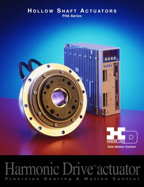
<strong>FHA</strong>-C series
<strong>FHA</strong>-C series Safety GuideCAUTIONS FOR ACTUATORS IN OPERATIONSDo not exceed the allowable torque of the actuator.• Be aware, that if a load arm attached to the output hits by accident an obstacle, the output shaft may become uncontrollable.Never connect cables directly to a power supply socket.• An actuator must not be operated without a corresponding driver.• Failure to observe this caution may lead to injury, fire or damage of the actuator.Protect the actuator from impact and shocks• Do not use a hammer to position the actuator during installation• Failure to observe this caution could damage the encoder and may cause uncontrollable operation.• Avoid handling of the actuator by its cables.• Failure to observe this caution may damage the wiring, causing uncontrollable or faulty operation.CAUTIONS FOR SERVO DRIVES IN APPLICATION DESIGNAlways use drivers under the following conditions:• Mount in a vertical position keeping sufficient distance to other devices to let heat generated by the driver radiate freely.• Ambient temperature: 0º to 50º• Ambient humidity: less than 95% RH (Non condensation)• No contamination by water, oil or foreign matters• No corrosive, inflammable or explosive gas Use sufficient noise suppressing means and safe grounding.• Keep signal and power leads separated.• Keep leads as short as possible.• Ground actuator and servo drive at one single point, minimum ground resistance class: D (less than 100 ohms)• Do not use a power line filter in the motor circuit. Pay attention to negative torque by inverse load.–Inverse load may cause damages of drivers.• Please consult our sales office, if you intent to apply products for inverse load. Use a fast-response typeground-fault detector designed for PWM inverters.• Do not use a time-delay-type ground-fault detector.CAUTIONS FOR SERVO DRIVES IN OPERATIONSNever change wiring while power is active:• Make sure of power non-active before servicing the products.• Failure to observe this caution may result in electric shock or personal injury.Do not touch terminals or inspect products at least 5 minutes after turning OFF power.• Otherwise residual electric charges may result in electric shock.• Make installation of products not easy to touch their inner electric components. Do not make a voltage resistance test.• Failure to observe this caution may result in damage of the control unit.• Please consult our sales office, if you intent to make a voltage resistance test.• Do not operate control units by means of power ON/OFF switching.• Start/stop operation should be performed via input signals.• Failure to observe this caution may result in deterioration of electronic parts.DISPOSAL OF AN ACTUATOR, A MOTOR, A CONTROL UNIT AND/OR THEIR PARTS• All products or parts have to be disposed of as industrial waste.• Since the case or the box of servo drives have a material indication, classify parts and dispose them separately.<strong>Harmonic</strong> <strong>Drive</strong> <strong>LLC</strong> 800-921-33322
Chapter 1 Overview of the <strong>FHA</strong>-C seriesChapter 1Overview of the <strong>FHA</strong>-C series<strong>FHA</strong> series servo actuators provide high torque and high accuracy rotary motion. The actuators are comprised of <strong>Harmonic</strong> <strong>Drive</strong>gear component from No. 17 to No.40 for precise motion control and a super-flat AC servomotors.The first feature of the <strong>FHA</strong> series actuators is their super-flat shape. The body width is less than half of our previous models.The second feature is a large through-hole in the center of the shaft, through which electric cables, air pipes, and evenlaser beams can be passed to supply power and signals to moving parts.The HA-655 series and th HA-675 series are dedicated servo drivers for the <strong>FHA</strong>-C series actuator to control its position and speed.The small and intelligent driver controls the <strong>FHA</strong>-C series actuators with great accuracy and reliability.<strong>FHA</strong>-C series actuators play an important role for driving various factory automation (FA) equipment; such as robot joints,alignment mechanisms for semiconductor and LCD equipment, ATC of machine tools, printing machine roller, etc.1-1 Features• Super-flat configuration<strong>FHA</strong>-C series actuator is the union of <strong>Harmonic</strong> <strong>Drive</strong> gear for precise motion control with a super-flat AC servomotor.The dimension from the coupling flange face to the actuator end is less than half the size of our previous models.The total thickness including the output flange is 30% flatter than our previous models. The compact size allows smallermachines to be designed.• Through-hole shaftThe center through-hole shaft allows for the insertion of electric cables, air pipes, or laser beams through the actuatorto supply power and signals to moving parts. This feature will simplify the driven machine.• High torque<strong>FHA</strong>-C series actuator outputs have a much higher torque per volume than direct drive motors. <strong>FHA</strong>-C series actuators have ahigher rating than our previous models.• High positioning accuracy<strong>FHA</strong>-C series actuators provide superior positioning accuracy. The <strong>FHA</strong>-25C/-32C/-40C -160 actuators achieve positioningaccuracy of 30 arc seconds (exceptionally, <strong>FHA</strong>-17C-160: 40arc seconds) as well as an encoder resolution of1,600,000 pulses per output revolution..• High torsion stiffness<strong>FHA</strong>-C series actuators provide from 30% to 100% greater torsion stiffness when compared with the previous series.This feature shortens positioning time and decreases the vibration during servo-lock stop.• Optional absolute encoder<strong>FHA</strong>-C series actuators allows to select an encoder system from two kinds of encoders for detecting a position: the one isan incremental encoder for general applications and the other is an absolute encoder (optional) for keeping its currentposition data all the time, even in power failure. The complex cable for the incremental encoder saves its wires resultedin increased reliability and simplified wiring.In this document, INC is attached for the descriptions for the incremental system only, and ABS is for the absolute system only.3
Chapter 1 Ordering Information for the <strong>FHA</strong>-C series1-2 Ordering Information for the <strong>FHA</strong> actuatorsModel number of <strong>FHA</strong>-C series actuators are as follows:<strong>FHA</strong>- 17 C-50-E -250-AC servo actuator <strong>FHA</strong> seriesFrame size: 17, 25, 32, 40DesignReduction ratio of <strong>Harmonic</strong> <strong>Drive</strong> gear50: 1/50100: 1/100160: 1/160Encoder specificationsUS: 14 wire incremental encoder (standard)E: 4 wire incremental encoder (optional)S: absolute encoder (optional)Encoder resolution250 : 2500 p/rev (incremental)248: 8192 p/rev (absolute)Optional specificationsDetails of the optional specifications are as follows:Optional spec. Details SymbolAC100V power supply available for <strong>FHA</strong>-17C, -25C, -32C only ABrake for motor for holding motor shaft BPosition sensors origin and end limits LCable-end connectors for motor cable (IP-20) & for encoder cable (IP-40) CCable outlet on back face from back bracket face KProtection equivalent to IP-67(technical arrangement is required) WClamp for output by built-in hydraulic mechanism with position sensors D5 meter cables 5m for each motor cable and encoder cable F524V available for <strong>FHA</strong>-17C only ENote 1: For more details, refer to chapter 4.Note 2: For requirement of two or more optional items, please contact to <strong>Harmonic</strong> <strong>Drive</strong> <strong>LLC</strong> for availability and delivery date.1-3 Combinations with servo drivesTwo series of HA-655 and HA-675 drives are available for use with <strong>FHA</strong>-C actuators dealing with their nominal current and encoder systems.The correct actuator/drive combinations are as follows:Incremental System INCAbsolute System ABSVolt <strong>FHA</strong>-17C <strong>FHA</strong>-25C <strong>FHA</strong>-32C <strong>FHA</strong>-40C <strong>FHA</strong>-17C <strong>FHA</strong>-25C <strong>FHA</strong>-32C <strong>FHA</strong>-40C-xx-US250 -xx-US250 -zz-US250 -XX-US250 -xx-S248 -xx-S248 -xx-S248 -xx-S24824V DDP-090-36 – – – – – – –DEP-090-36 – – – – – – –AC200 RTL-230-18 RTL-230-18 RTL-230-18 RTL-230-36(1/50) REL-230-18 REL-230-18 REL-230-18 REL-230-36(1/50)REL-230-18 REL-230-18 REL-230-18 REL-230-36(1/50) – – – REL-230-18(1/100,1/160)– – – RTL-230-18(1/100,1/160) – – – –– – – REL-230-18(1/100,1/160) – – – –AC100 RTL-230-18 RTL-230-36(1/50) RTL-230-36(1/50,1/100) – REL-230-18 REL-230-18 REL-230-36(1/50,1/100) –REL-230-18 REL-230-36(1/50) REL-230-36(1/50,1/100) – – – REL-230-18(1/160) –– RTL-230-18(1/100,1/160) RTL-230-18(1/160) – – – REL-230-18 REL-230-36(1/50)– REL-230-18(1/100,1/160) REL-230-18(1/160) – – – – REL-230-18(1/100,1/160)200V HA-655-2-200 HA-655-2-200 HA-655-4-200 HA-655-4-200 HA-655-2A-200 HA-655-2A-200 HA-655-4A-200 HA-655-4A-200HA-675-2-200 HA-675-2-200 HA-675-4-200 HA-675-4-200 HA-675-2A-200 HA-675-2A-200 HA-675-4A-200 HA-675-4A-200100V HA-655-2-100 HA-655-4-100 HA-655-4-100 – HA-655-2A-100 HA-655-4A-100 HA-655-4A-100 –HA-675-2-100 HA-675-4-100 HA-675-4-100 – HA-675-2A-100 HA-675-4A-100 HA-675-4A-100 –<strong>Harmonic</strong> <strong>Drive</strong> <strong>LLC</strong> 800-921-3332 4
Chapter 1 Overview of the <strong>FHA</strong>-C series1-4 Specifications of <strong>FHA</strong>-C actuators1-4-1 INCREMENTAL SYSTEM INCSpecifications of <strong>FHA</strong>-C series actuators with the 14 Wire Incremental Encoder are as follows:Model <strong>FHA</strong>-17C-xx-US250 <strong>FHA</strong>-25C-xx-US250 <strong>FHA</strong>-32C-xx-US250 <strong>FHA</strong>-40C-xx-US25050 100 160 50 100 160 50 100 160 50 100 160Maximum Torque Note 2 N•m 39 57 64 150 230 260 281 398 453 500 690 820Maximum Speed r/min 96 48 27 90 45 28 80 40 25 70 35 22Torque Constant 1) 200V N•m/A 21 42 67 22 45 72 27 54 86 31 64 102100V N•m/A 11 21 33 11 22 36 13 27 43 15 32 51Maximum Current 200V A 2.1 1.6 1.1 7.3 5.6 4.0 11.4 8.0 5.9 17.3 11.8 9.0Note 2 100V A 4.2 3.2 2.2 15 11 8.0 23 16 12 35 24 18EMF Voltage Constant200V V/(r/min) 2.3 4.7 7.5 2.5 5.1 8.1 3.0 5.9 9.5 3.6 7.2 11.4100V V/(r/min) 1.2 2.4 3.8 1.3 2.6 4.1 1.5 3.0 4.8 1.8 3.6 5.7Phase Resistance200V (20ºC) 7.9 2.6 1.0 0.73100V (20ºC) 2.0 0.65 0.25 0.18Phase Inductance200V mH 6.0 2.6 1.3 1.5100V mH 1.5 0.65 0.33 0.38Inertia of Actuator(GD 2 /4) kg•m 2 0.17 0.67 1.7 0.81 3.2 8.3 1.8 7.1 18.1 4.9 19.5 50(J) kgf•cm•s 2 1.7 6.9 17 8.3 33 85 18 72 185 50 200 510Reduction Ratio 1:50 1:100 1:160 1:50 1:100 1:160 1:50 1:100 1:160 1:50 1:100 1:160Allowable Radial Load kN 2.9 4.9 9.5 14.7Allowable Axial Load kN 9.8 14.7 24.5 39.2Allowable Torsional Moment N•m 188 370 530 690Moment stiffness N•m/rad 220x10 3 490x10 3 790x10 3 1400x10 3One-wayPositioning Accuracyarc-sec 60 40 40 40 30 30 40 30 30 40 30 30Motor encoder2500 pulse/rev.Quad encoder-resolution Note 4 Pulse/rev 500,000 1,000,000 1,600,000 500,000 1,000,000 1,600,000 500,000 1,000,000 1,600,000 500,000 1,000,000 1,600,000Mass Kg 2.5 4.0 6.5 12EnclosureTotally enclosed, self-cooling (equivalent to IP44)Environmental conditions Service / Storage temperature : 0~40ºC / -20 ~ 60ºCService / storage humidity : 20~80%RH (no condensation)Vibration / impact resistance : 24.5m/s 2 (freq:10-400Hz) , shock resistance 294 m/s 2No dust, no metal powder, no corrosive gas, no inflammable gas, no oil mist;install in room, no direct sunlightAltitude: less than 1,000 meters above sea levelMotor insulationInsulation resistance: 100MΩ or more (by DC500V insulation tester)Withstanding voltage: AC1500V / 1 minuteInsulation class: FOrientationAll positionNote 1: The table shows output values of actuators.Note 2: Values for saturated temperature under the conditions that the actuator is driven by an appropriate HA-655 or HA-675 drive.Note 3: Quad encoder resolutions are obtained by [motor encoder resolution] x 4 x [reduction ratio]5
Chapter 1 Overview of the <strong>FHA</strong>-C series1-4-2 Absolute SystemSpecifications of <strong>FHA</strong>-C series actuators with an Absolute Encoder are as follows:Model <strong>FHA</strong>-17C-xx-US248 <strong>FHA</strong>-25C-xx-US248 <strong>FHA</strong>-32C-xx-US248 <strong>FHA</strong>-40C-xx-US24850 100 160 50 100 160 50 100 160 50 100 160Maximum Torque N•m 39 57 64 150 230 260 281 398 453 500 690 820Maximum Speed r/min 96 48 27 90 45 28 80 40 25 70 35 22Torque Constant 1) 200V N•m/A 21 42 67 22 45 72 27 54 86 31 64 102100V N•m/A 11 21 33 11 2.2 36 13 27 43 15 32 51Maximum Current 200V A 2.1 1.6 1.1 7.3 5.6 4.0 11.4 8.0 5.9 17.3 11.8 9.0Note 2 100V A 4.2 3.2 2.2 15 11 8.0 23 16 12 35 24 18EMF Voltage Constant200V V/(r/min) 2.3 4.7 7.5 2.5 5.1 8.1 3.0 5.9 9.5 3.6 7.2 11.4100V V/(r/min) 1.2 2.4 3.8 1.3 2.6 4.1 1.5 3.0 4.8 1.8 3.6 5.7Phase Resistance200V (20ºC) 7.9 2.6 1.0 0.73100V (20ºC) 2.0 0.65 0.25 0.18Phase Inductance200V mH 6.0 2.6 1.3 1.5100V mH 1.5 0.65 0.33 0.38Inertia of Actuator(GD 2 /4) kg•m 2 0.2 0.7 1.9 0.8 3.4 8.6 1.8 7.3 18.1 5.0 19.8 50.7(J) kgf•cm•s 2 1.7 7.5 19.2 8.6 34.2 87.6 18.5 74.2 185 50.5 202 517Reduction Ratio 1:50 1:100 1:160 1:50 1:100 1:160 1:50 1:100 1:160 1:50 1:100 1:1 60Allowable Radial Load kN 2.9 4.9 9.5 14.7Allowable Axial Load kN 9.8 14.7 24.5 39.2Allowable Torsional Moment N•m 188 370 530 690Moment stiffness N•m/rad 220x10 3 490x10 3 790x10 3 1400x10 3One-wayPositioning Accuracyarc-sec 60 40 40 40 30 30 40 30 30 40 30 30Motor encoder8192 p/r (13 bit)Quad encoder-resolution Note 4 Pulse/rev 409,600 819,200 1,310,720 409,600 819,200 1,310,720 409,600 819,200 1,310,720 409,600 819,200 1,310,720Mass Kg 2.9 4.5 7.1 13EnclosureTotally enclosed, self-cooling (equivalent to IP44)Environmental conditions Service / Storage temperature : 0~40ºC / -20 ~ 60ºCService / storage humidity : 20~80%RH (no condensation)Vibration / impact resistance : 24.5m/s 2 (freq:10-400Hz) , shock resistance 294 m/s 2No dust, no metal powder, no corrosive gas, no inflammable gas, no oil mist;install in room, no direct sunlightAltitude: less than 1,000 meters above sea levelMotor insulationInsulation resistance: 100MΩ or more (by DC500V insulation tester)Withstanding voltage: AC1500V / 1 minuteInsulation class: FOrientationAll positionNote 1: The table shows output values of actuators.Note 2: Values for saturated temperature under the conditions that the actuator is driven by an appropriate HA-655 or HA-675 drive.Note 3: Quad encoder resolutions are obtained by [motor encoder resolution] x 4 x [reduction ratio]<strong>Harmonic</strong> <strong>Drive</strong> <strong>LLC</strong> 800-921-3332 6
Chapter 1 Overview of the <strong>FHA</strong>-C series1-5 External dimensions of <strong>FHA</strong> actuators1-5-1 Incremental Systems INCThe external drawings are shown as follows:• <strong>FHA</strong>-17C-xx-US250INC• <strong>FHA</strong>-25C-xx-US250INC7Note 1: The parenthesized dimensions are applied for the actuators with a brake option.Note 2: For detail dimensions, make sure of them referring our drawings for shipping.
Chapter 1 Overview of the <strong>FHA</strong>-C series• <strong>FHA</strong>-32C-xx-US250INCUnit: mm (third angle projection)• <strong>FHA</strong>-40C-xx-US250INCNote 1: The parenthesized dimensions are applied for the actuators with a brake option.Note 2: For detail dimensions, make sure of them referring our drawings for shipping.<strong>Harmonic</strong> <strong>Drive</strong> <strong>LLC</strong> 800-921-33328
Chapter 1 Overview of the <strong>FHA</strong>-C series1-5-2 Absolute Systems ABSThe external drawings are shown as follows:• <strong>FHA</strong>-17C-xx-S248 ABS• <strong>FHA</strong>-25C-xx-S248 ABS9Note 1: The parenthesized dimensions are applied for the actuators with a brake option.Note 2: For detail dimensions, make sure of them referring our drawings for shipping.
Chapter 1 Overview of the <strong>FHA</strong>-C seriesUnit: mm (third angle projection)• <strong>FHA</strong>-32C-xx-S248 ABS• <strong>FHA</strong>-40C-xx-S248 ABSNote 1: The parenthesized dimensions are applied for the actuators with a brake option.Note 2: For detail dimensions, make sure of them referring our drawings for shipping.<strong>Harmonic</strong> <strong>Drive</strong> <strong>LLC</strong> 800-921-3332 10
Chapter 1 Overview of the <strong>FHA</strong>-C series1-6 Mechanical accuracy of <strong>FHA</strong> actuatorsThe machining accuracy of the output flange and the mounting flange are indicated in the table below.Machined accuracy of the output flangeunit: mmMachined parts <strong>FHA</strong>-17C <strong>FHA</strong>-25C <strong>FHA</strong>-32C <strong>FHA</strong>-40C1. Axial run-out of output flange 0.010 0.012 0.012 0.0142. Radial run-out of output flange 0.010 0.012 0.012 0.0143. Parallelism between output flange and mounting flange 0.040 0.050 0.050 0.0604. Concentricity between output flange to fitting face 0.040 0.050 0.050 0.060Note: All values are T.I.R (Total Indicator Reading).The measuring for the values are as follows:• Axial run-out of output flangeThe indicator (1) on a fixed portion measures the axial run-out(T.I.R.) of perimeter of output flange for one revolution.2B• Radial run-out of output flangeThe indicator (2) on a fixed portion measures the radial run-out(T.I.R.) of perimeter of output flange for one revolution.A4 A4 A13 B3 B• Parallelism between output flange and mounting flangeThe indicator (3) on the output flange measures the axial run-out(T.I.R.) of each perimeter of both sides of the fixing flangefor one revolution.• Concentricity between output flange to fitting faceThe indicator (4) on the output flange measures the radial run-out(T.I.R.) of each surface of both fitting face (drive-end sideand opposite side) for one revolution.(4)(3)(2)(1)(4)(3)11
Chapter 1 Overview of the <strong>FHA</strong>-C series1-7 One-way positioning accuracyThe one-way positioning accuracy means the maximumpositional difference between a commanded theoreticalposition and its actual angular position for serial positioningin one revolution when approached from the samedirection.(refer to JIS B-6201-1987)The one-way positioning accuracy of <strong>FHA</strong>-C actuatorsis almost equal to the angular positioning accuracy of the<strong>Harmonic</strong> <strong>Drive</strong> gear, because the effect on thepositioning error of the built-in motor is reducted to its1/50 or 1/100 or1/160 by the gearing.Commanded stopping positionPosition differenceActual stoppingpositionThe uni-directional positioning accuracy is shown in the table below:Start positionModel <strong>FHA</strong>-17C <strong>FHA</strong>-25C <strong>FHA</strong>-32C <strong>FHA</strong>-40CItem 1:50 1:100 1:160 1:50 1:100 1:160 1:50 1:100 1:160 1:50 1:100 1:160Uni-directionalpositioning accuracyarc second 60 40 40 40 30 30 40 30 30 40 30 301-8 Encoder resolutionThe motors of <strong>FHA</strong>-C actuators are equipped with an incremental encoder of 2500 resolutions or an absolute encoder of 1892 resolutions.Because the motor rotation is reduced to 1/50 or 1/100 or 1/160 by the gear component, the resolution of the output flange is 50 or 100 or160 times the encoder revolution. Additionally, the incremental encoder signal is used in signal is used in quadrature.The following high resolutions are obtained:Encoder Incremental AbsoluteEncoder resolution 2,500 (10,000: quadruplicated) 8,192Reduction Ratio 1:50 1:100 1:160 1:50 1:100 1:160Resolution of output flange Pulse/rev 500,000 1,000,000 1,600,000 409,600 819,200 1,310,720Resolvable angle per pulse arc sec 2.6 1.3 0.8 3.2 1.6 1.0(All values are approximate.)1-9 Torsional Stiffness of Actuators1-9-1 Moment stiffnessThe moment stiffness refers to the torsional stiffness whena moment load is applied to the output flange of the actuator(shown in the figure to the right).For example, when a load is applied to the end of an armattached on the output flange, the face of the output flange tiltsin proportion to the moment load. The moment stiffness isexpressed as the torsional moment/angle.DO NOT APPLY TORQUE, LOAD OR THRUST TO THE SLEEVE DIRECTLY.Since the sleeve is adhered to the output flange, the adhered sleeve may be detachedfrom the output flange by the abnormal torque or load.Model <strong>FHA</strong>-17C <strong>FHA</strong>-25C <strong>FHA</strong>-32C <strong>FHA</strong>-40CItemN•m/rad 220 x 10 3 490 x 10 3 790 x 10 3 1400 x 10 3Moment Stiffness Kgf•m/rad 22 x 10 3 50 x 10 3 80 x 10 3 140 x 10 3Kgf•m/arc-min 6.5 15 23 42<strong>Harmonic</strong> <strong>Drive</strong> <strong>LLC</strong> 800-921-333212
Chapter 1 Overview of the <strong>FHA</strong>-C series1-9-2 Torsional StiffnessWhen a torque is applied to the output flange of the actuator with the motor locked,the resulting torsional wind up is near proportional to the torque.TorsionAThe upper right figure shows the torsional stiffness characteristics of the output flangeapplying torque starting from zero to plus side [+T0] and minus side [–T0].This trajectory is called torque-torsion characteristics which typically followsa loop 0→A→B→A’→B’→A as illustrated. The torsional stiffness of the<strong>FHA</strong>-C actuator is expressed by the slope of the curve that is a spring rate(wind-up) (N•m/rad).-T0HysteresisLossBO1O+T 0TorqueThe torsional stiffness may be evaluated by dividing torque-torsion characteristicscurve into three major regions. The spring rate of each region is expressedK1, K2, and K3 respectively.A1K1: spring rate for torque region 0-T1K2: spring rate for torque region T1-T2K3: spring rate for torque region over T2TorsionThe wind-up for each region is expressed as follows:K3• Wind-up for torque region 0-T1: ϕ =TK1T - T 1• Wind-up for torque region T1-T2: ϕ = θ1 +K2020 K11K2T - T 2• Wind-up for torque region over T2: ϕ = θ2 +K3 Ø ϕ : Wind-upOT1T2TorqueThe table below shows T1-T3, K1-K3, and θ1-θ2 values of each actuator.Model <strong>FHA</strong>-17C <strong>FHA</strong>-25C <strong>FHA</strong>-32C <strong>FHA</strong>-40CReduction Ratio 1:50 1:100 1:160 1:50 1:100 1:160 1:50 1:100 1:160 1:50 1:100 1:160T1 N•m 7.0 7.0 7.0 29 29 29 54 54 54 108 108 108kgf•m 0.7 0.7 0.7 3.0 3.0 3.0 5.5 5.5 5.5 11 11 11K1 x10 4 N•m/rad 1.1 1.3 1.3 4.7 6.1 6.1 8.8 11 11 17 21 21kgf•m/arc min 0.32 0.4 0.4 1.4 1.8 1.8 2.8 3.2 3.2 5.0 6.3 6.3θ1 x10 -4 rad 6.4 5.1 5.1 6.2 4.8 4.8 6.1 4.9 4.9 6.4 5.1 5.1arc min 2.2 1.8 1.8 2.1 1.7 1.7 2.1 1.7 1.7 2.2 1.8 1.8T2 N•m 25 25 25 108 108 108 196 196 196 382 382 382kgf•m 2.5 2.5 2.5 11 11 11 20 20 20 39 39 39K2 K2x10 4 N•m/rad 1.3 1.7 1.7 6.1 7.7 7.7 11 14 14 21 29 29kgf•m/arc min 0.4 0.5 0.5 1.8 2.3 2.3 3.4 4.2 4.2 6.3 8.5 8.5θ2 x10 -4 rad 19.5 15.6 15.6 19.2 15 15 19.1 15.1 15.1 19.3 14.7 14.7arc min 6.7 5.4 5.4 6.6 5.1 5.1 6.4 5.2 5.2 6.6 5.0 5.0K3 x10 4 N•m/rad 2.0 2.5 2.5 8.4 11 11 15 20 20 30 37 37kgf•m/arc min 0.6 0.75 0.75 2.5 3.3 3.3 4.5 5.8 5.8 9 11 11The table below shows torque-wind-up relation for reference.(unit:N•m)Model <strong>FHA</strong>-17C <strong>FHA</strong>-25C <strong>FHA</strong>-32C <strong>FHA</strong>-40CReduction Ratio 1:50 1:100 1:160 1:50 1:100 1:160 1:50 1:100 1:160 1:50 1:100 1:1602 arc-min 6.3 8.1 8.1 27 37 37 51 63 63 98 129 1294 arc-min 14 18 18 62 82 82 117 148 148 220 300 3006 arc-min 22 29 29 97 136 136 179 243 243 340 490 49013
Chapter 1 Overview of the <strong>FHA</strong>-C seriesRadiation plate 400x400x20(mm)Radiation plate 500x500x25(mm)Acc./dec. rangeAcc./dec. rangeTorque [Nm]50% duty rangeContinuous rangeTorque [Nm]50% duty rangeContinuous rangeSpeed [r/min]Speed [r/min]Radiation plate 400x400x20(mm)Radiation plate 500x500x25(mm)Acc./dec. rangeAcc./dec. rangeTorque [Nm]50% duty rangeContinuous rangeTorque [Nm]50% duty rangeContinuous rangeSpeed [r/min]Speed [r/min]Radiation plate 400x400x20(mm)Radiation plate 500x500x25(mm)Acc./dec. rangeAcc./dec. rangeTorque [Nm]50% duty rangeContinuous rangeTorque [Nm]50% duty rangeContinuous rangeSpeed [r/min]Speed [r/min]<strong>Harmonic</strong> <strong>Drive</strong> <strong>LLC</strong> 800-921-333216
Chapter 1 Overview of the <strong>FHA</strong>-C series1-14 Cable specificationsThe following tables show the lead specifications for the motors and the encoders of the <strong>FHA</strong>-C actuators.• Motor CableColorStandardBrake optionRed Motor phase-U Motor phase-UWhite Motor phase-V Motor phase-VBlack Motor phase-W Motor phase-WGreen/yellow PE PEBlue No connection BrakeYellow No connection Brake(Shield) FG FG• Encoder Lead for 14 Wire Incremental Encoder INCColor Signal Color SignalRed Vcc Black GNDGreen A Green/White AGray B Gray/White BYellow Z Yellow/White ZBrown U Brown/White UBlue V Blue/White VOrange W Orange/White WOutput circuitInput circuit of user’s device (Ex.)V CCAM26LS31C (Equivalent)A,B,Z,U,V,W_A, _ B, _ Z, _ U, _ V, _ WR1AM26LS32C (Equivalent)V CCGNDR1:120_C1C2GNDFGFGVoltage strength of capacitor C1,C2 : 50V• Encoder Lead for 4 Wire Incremental Encoder INCColor Signal ReferenceRed +5V PowerBlack 0V SupplyYellow SD Serial SignalBlue SD Differential Output(Shield)FG• Encoder Lead for Absolute Encoder ABS17Color Signal ReferenceRed +5VBlack 0V Power SupplyWhite0VYellow SD Serial SignalBlue SD Differential OutputOrange BAT+ Battery+Gray BAT- Battery-Green CLR Clear Signal(Shield)FG
Chapter 1 Overview of the <strong>FHA</strong>-C series1-15 Signal WaveformSignal waveform specifications of new version <strong>FHA</strong>-17C / 25C / 32C / 40C for US marketFigure 1 shows A, B and Z signal and relationship with U signal with CW rotationfacing the encoder end (the end of the actuator output shaft.)Figure 1a, b, c, d = 1/4T ± 1/10T(a + b), (b+c) = 1/2T ± 1/8TTz = 1/2T ~ 3/2T(The Z phase includes a HIGH statein case of both of A and B phase isHIGH state.)T = 360º / 2500a < ± 10º (Mechanical angle)Figure 2shows U, V, and W signal and relationship[ with motor’s EMF with CW rotationfacing the encoder end (the end of the actuator output shaft.)Figure 2Voltage of U-W (G) means of voltageof U terminal grounding W terminal.R = 60º ± 3ºHn = 10º ± 3º (Mechanical angle)a < ± 10º / 6 (Mechanical angle)Encoder Output<strong>Harmonic</strong> <strong>Drive</strong> <strong>LLC</strong> 800-921-3332 18
Chapter 2 Guidelines for sizingChapter 2Selection guidelinesInertia2(kg•m ) (kgf•cm•s 2)1000 100002-1 Allowable load inertiaTo achieve high accuracy performance, select an<strong>FHA</strong> actuator wherein the allowable moment of inertia(reference value) is greater than the load inertia.Refer to appendix 1 for the calculation of moment inertia.When selecting the actuator make certain that the loadinertia and the maximum speed are less than the allowablevalues that are indicated in the table below.100 1000<strong>FHA</strong>-40C-160<strong>FHA</strong>-32C-16010 100 <strong>FHA</strong>-25C-1601 10 <strong>FHA</strong>-17C-160<strong>FHA</strong>-40C-100<strong>FHA</strong>-32C-100<strong>FHA</strong>-40C-50<strong>FHA</strong>-25C-100<strong>FHA</strong>-32C-50<strong>FHA</strong>-17C-100<strong>FHA</strong>-25C-50<strong>FHA</strong>-17C-500.1 10 20 40 60 80 100 120Max. speed (r/min)Actuator model <strong>FHA</strong>-17C <strong>FHA</strong>-25C <strong>FHA</strong>-32C <strong>FHA</strong>-40CReduction ratio 1:50 1:100 1:160 1:50 1:100 1:60 1:50 1:100 1:160 1:50 1:100 1:160Maximum speed (r/min) 96 48 30 90 45 28 80 40 25 70 35 22Moment of inertia kg•m 2 0.17 0.67 1.7 0.81 3.2 8.3 1.8 7.1 18.1 4.9 19.5 50of actuator kgf•cm•s 2 1.7 6.9 17 8.3 33 85 18 72 185 50 200 510Allowable moment kg•m 2 0.54 2.1 5.1 2.4 10 25 5.4 21 54 15 60 150of inertia kgf•cm•s 2 5.4 21 52 24 100 260 55 210 550 150 610 15002-2 Variable load inertia<strong>FHA</strong>-C series actuators include <strong>Harmonic</strong> <strong>Drive</strong> gear that has a highreduction ratio. Because of this there are minimal effects of variableload inertias to the servo drive system. In comparison to direct servosystems this benefit will drive the load with a better servo response.For example, assume that the load inertia increases to N-times duringits motion (for example, robot arms). The effect of the variable loadinertia to the [total inertia converted into motor shaft] is as follows:The symbols in the formulas are:J S : Total inertia converted into motor shaftJ M : Moment inertia of motorR: Reduction ratio of <strong>FHA</strong> actuatorL: Ratio of load inertia to motor inertiaN: Variation ratio of load inertia• Direct driveBefore: J S = Jm ( 1 + L ) After: Js’ = Jm ( 1+ NL )Ratio:Js’/Js = 1 + NL1 + L• <strong>FHA</strong> actuator driveBefore: Js = Jm( 1+ L ) After: Js’ = Jm ( 1 + NL ) Ratio: Js’/Js =R2R21 + NL / R21 + L / R2In the case of the <strong>FHA</strong> actuator drive, as the reduction ratio is [R=50], [R=100] or [R160] and the square of the reduction ratio[R 2 =2500], [R 2 =10000] or [R 2 =25600] the denominator and the numerator of the ratio are almost [1]. Then the ratio is [F=1].This means that <strong>FHA</strong> drive systems are hardly effected by the load inertia variation. Therefore, it is not necessaryto take the load inertia variation into consideration for selecting an <strong>FHA</strong> actuator or for setting up the HA-675 or HA-655 driver.19
Chapter 2 Guidelines for sizing• Calculating average loads: average radialand axial loads, average output speedWhen the radial and/or axial loads vary during motion, calculate and verifythe life of the cross roller bearing converting the loads to their average values.• Average radial load: Frav10/3n 1 t 1| Fr 1| 10/3 +n 2 t 2| Fr 2| 10/3 ...n n t n| Frn10/3Faav= (2)√ n 1 t 1 + n 2 t 2 + ... +nn tnNote: "Fr 1 " is the maximum radial load in "t 1 " range,and "Fr 3 " is the maximum radial load in "t 3 " range.– Axial load +Fr 1Fr 2Fr 3Fa 1Fa 2Time• Average axial load: Faav10/3n 1 t 1| Fa 1| 10/3 +n 2 t 2| Fa 2| 10/3 ...n n t n| Fa n| 10/3√Faav= (3)n 1 t 1 + n 2 t 2 + ... +n n t n– Axial load +Fa 3TimeNote: "Fa 1 " is the maximum radial load in "t 1 " range,and "Fa 3 " is the maximum radial load in "t 3 " range.t 1 t 2 t 3• Average output speed: Nav10/3n 1 t 1 +n 2 t 2 +...n n t n (4)Nav=t 1 + t 2 + ... + t n– Axial load +n 1n 2n 3Time• Calculating radial load factor and axial load factorBoth load factors are different with average loads as follows:• When the right formula is satisfied,X=1.0, and Y=0.45FaavFrav + 2(Frav ( L r+ R ) + Faav.La ) /dp1.5 (5’)Where, the variables of the formula are:Mmax: Maximum torsional moment in N•m(kgf•m); obtained by the formula (1)Frmax: Maximum radial load in N(kgf); See Fig.1.Famax: Maximum axial load in N(kgf); See Fig.1.Lr, La: Loading point in mm; See Fig.1.R: Offset; See Fig.1 and Table 1.dp: Circular pitch of roller: See Fig.1 and Table 1.21
Chapter 2 Guidelines for sizing• Equivalent dynamic radial loadThe equivalent dynamic radial load is:2 (Frav (Lr + R) + Faav . La)P C = X . ( Frav + ) + Y .Faav (6)dpWhere, the variables of the formula are:Frav: Average radial load in N(kgf); obtained by formula (2).Faav: Average axial load in N(kgf); obtained by formula (3).dp: Circular pitch of roller: See Fig.1 and Table 1.X: Radial load factor; obtained by formula (5)Y: Axial load factor; obtained by formula (5')Lr, La: Loading point in mm; See Fig.1.R: Offset; See Fig.1 and Table 1.• Life of cross roller bearingCalculate the life of cross roller bearing with the formula below:10 6 CL B-10 = x (7)60 x Nav ( fw.Pc )10/3Where, the variables of the formula are:LB-10: Life of cross roller bearing in hourNav: Average output speed in r/min; obtained by formula (4).C: Basic dynamic load rating in N (kgf). See Table 1.Pc: Average dynamic radial load in N (kgf); obtained by formula (6) below.fw: Load factor:For smooth operation without shock or vibration: fw=1 to 1.2For normal operation: fw=1.2 to 1.5For operation with shock and/or vibration: fw=1.5 to 3• Life of cross roller bearing for swaying motionCalculate the life of cross roller bearing with the formula below:10 6 90 CL = x x (8)OC60 x n1 θ ( fw.Pc )Where, the variables of the formula are:Loc: Life of cross roller bearing in hourn1: Average output speed in r/min; obtained by formula (4).C: Basic dynamic load rating in N (kgf). See Table 1.Pc: Equivalent dynamic radial load in N (kgf); obtained by formula (6).fw: Load factor:For smooth operation without shock or vibration: fw=1 to 1.2For normal operation: fw=1.2 to 1.5For operation with shock and/or vibration: fw=1.5 to 3θ: Half of sway angle; See the right figure.When the sway angle is less than 5 degrees, consult <strong>Harmonic</strong> <strong>Drive</strong> Systems,because fretting wear may occur for the operation caused by no oil filmbetween the race and the rolling element.10/3Inertia2(kg•m ) (kgf•cm•s 2)1000 10000100 1000<strong>FHA</strong>-40C-160<strong>FHA</strong>-32C-16010 100 <strong>FHA</strong>-25C-1601 10 <strong>FHA</strong>-17C-160<strong>FHA</strong>-40C-100<strong>FHA</strong>-32C-100<strong>FHA</strong>-40C-50<strong>FHA</strong>-25C-100<strong>FHA</strong>-32C-50<strong>FHA</strong>-17C-100<strong>FHA</strong>-25C-50<strong>FHA</strong>-17C-500.1 10 20 40 60 80 100 120Max. speed (r/min)Sway Motion<strong>Harmonic</strong> <strong>Drive</strong> <strong>LLC</strong> 800-921-3332 22
Chapter 2 Guidelines for sizing• Equivalent static radial loadEquivalent static radial load is obtained by formula (9) below.2MmaxP = Frmax + O + 0.44 Famax (9)dpWhere, the variables of the formula are:Po: Equivalent static radial load in N (kgf)Mmax: Maximum torsional moment in N•m(kgf•m); obtained by the formula (1)Frmax: Maximum radial load in N(kgf); See Fig.1.Famax: Maximum axial load in N(kgf); See Fig.1.dp: Circular pitch of roller: See Fig.1 and Table 1.• Static safety factorGenerally, the static safety factor is limited by the basic static load rating (Co).However, for the heavy duty, the factor is limited by the following formula:Cofs = (10)PoWhere, the variables of the formula are:fs:Static safety factor;For precise positioning operation: fs > 3For operation with shock and/or vibration: fs > 2For normal operation: fs > 1.5Co: Basic static load rating in N (kgf). See Table 1.Po: Equivalent static radial load in N (kgf); obtained by formula (9).23
Chapter 2 Guidelines for sizing2-4 Duty cyclesWhen a duty cycle includes many frequent start and stop operations,the actuator generates heat by high starting and braking current.Therefore, it is necessary to study the duty cycle profile.Screw pitch (mm)30Speed (r/min)The study is as follows:2-4-1 Actuator speedCalculate the required actuator speed (r/min) to drive the load.For linear motion, convert with the formula below:Linear speed (mm/min)Rotary speed (r/min) = (9)Pitch of screw (mm)Select a reduction ratio from [50], [100] and [160] of an actuatorof which the maximum speed is more than the required speed.10335r/min50r/min70r/min100r/min130 100 300 1000 3000Li near speed (mm/min)20r/min2-4-2 Load inertiaCalculate the load inertia driven by the <strong>FHA</strong>-C series actuator.Refer to appendix 1 for the calculation.Tentatively select an <strong>FHA</strong>-C actuator referring to section[2-1 allowable load inertia] with the calculated value.2-4-3 Load torqueCalculate the load torque as follows:• Rotary motionThe torque for the rotating mass [W] on the friction ring of radius [r]as shown in the figure to the right.Friction:Mass: WRadius:rT = 9.8 x µ x W x rT: torque (N•m)µ : coefficient of frictionW: mass (kg)r: radius of friction face (m)300Ex. torque calculation (friction=0.1)<strong>FHA</strong> : (ratio: 1/50) 30% torque of maximum torque10 N•m7 N•m5 N•m20 N•m 50 N •m 100 N•m 200 N•m30 N•m300 N•m1003 N•mIn the right graph, the oblique solid linesfor torque have been calculated with thecoefficient of the friction of µ=0.1.The oblique dot-chain lines show20% torque of actuators converted from300% torque corresponding to its maximum torque.30102 N•m1 N•m<strong>FHA</strong>- 17C-50<strong>FHA</strong>- 40C-50<strong>FHA</strong>-32C-50<strong>FHA</strong>-25C-5030 100 300 1000 3000Mass: W (k g)<strong>Harmonic</strong> <strong>Drive</strong> <strong>LLC</strong> 800-921-333224
Chapter 2 Guidelines for sizing• Horizontal linear motionThe following formula calculates the torque for horizontallinear motion of mass [W] fed by the screw of pitch [P].T = 9.8 x µ x W xP2 x πT : torque (N•m)µ : coefficient of frictionW : mass (kg)P : screw pitch (m)Pitch: PMass: WFriction:• Vertical linear motionThe following formula calculates the torque for verticallinear motion of mass [W] fed by the screw of pitch [P].T = 9.8 x W xP2 x π2-4-4 Acceleration time and deceleration timeCalculate acceleration and deceleration times for the selected actuator.Acceleration:ta = (Ja + Jl) x 2 x π Nx60 Tm – TlMass: WPitch: PDeceleration:td = (Ja + Jl) x 2 x π Nx60 Tm + 2 x Tf – TlTa: acceleration time (sec)Td: deceleration time (sec)Ja: actuator inertia (kg•m 2 )JL: load inertia (kg•m 2 )N: actuator speed (r/min)TM: maximum torque of actuator (N•m)TF: actuator friction torque at max. speed (N•m)TF = KT x IM - TMwhere, KT: torque constant (N•m/A)IM: maximum current (A)TL: load torque (N•m)note that the polarity of the load torque isplus (+) for counter direction of revolution,and minus (-) for same direction.NSpeedtatdTime• Example 1The load conditions are: Rotary speed: 60r/minMoment of inertia: 1.5 kg•m 2Load torque is so small as to be neglected.(1) Referring the figure in section 2-1, <strong>FHA</strong>-25C-50 actuator is selected for the load.(2) Referring the specification table provided in section 1-4, JA=0.81 kg•m 2 , TM =150 N•m, KT=22 N•m/A,and IM =7.3A are obtained for the <strong>FHA</strong>-25C-50.(3) TF = 22 x 7.3 – 150 = 10.6 N•m is obtained with the formula above.(4) Acceleration and deceleration times are: ta = (0.81+1.5 ) x 2 x π / 60 x 60 / 150 = 0.097 std = (0.81+1.5) x 2 x π / 60 x 60 / (150 + 2 x 10.6) = 0.085 s(5) If the calculated acceleration times are too long, correct the situation by:• Reducing load moment of inertia25• Selecting an actuator with a larger frame size
Chapter 2 Guidelines for sizing2-4-5 Calculating equivalent dutySpeedThe load conditions, which is torque, speed, moment of inertia,acceleration/deceleration time, loading time, are limited by theactuator to drive the load. To select the proper actuator, theequivalent duty of the load should be calculated.The %ED (percent equivalent duty) is:Nta tr td tst: duty cycleTime%ED = Kla x ta + Klr x tr + Kld x td x 100twhere, ta: acceleration time in secondtd: deceleration time in secondtr: driving time in secondt: single cycle time in secondKla: duty factor for acceleration timeKlr: duty factor for driving timeKld: duty factor for deceleration timeTorqueTaTrTaTime• Example 2: getting duty factors of Kla, Klr and KldWith an example of the duty factor graph for <strong>FHA</strong>-25C-50 actuator,the way of getting the duty factors of Kla, Klr and Kld is describedas follows:The load conditions are the same as the example described inexample 1: the inertia load is accelerated by the maximumtorque,and is driven with a constant speed, and decelerated by themaximum torque. The displacement angle is 120 degrees andthe cycle time is 2.0 s.(1) Kla, and Kld: the speed is desired at 30 r/min asthe average of 0 and 60 r/min.Then, Kla = Kld = 7.0 from the graph.KLr(2) Klr (ex.: Klr =1.0) from the graph pointing the load torqueTr (ex. Tr= 0) and driving speed (ex: Nr=60r/min).(3) The driving time is calculated as the area of thetrapezoid of speed-time graph. Then thedisplacement angle is:θ = (N / 60) x {tr + (ta + td) / 2} x 360Then, tr = θ / (6 x N) – (ta +td) /2As the 120 deg. is equal to 0.33rev (=120/360), the driving angle at the speed of 60r/min (=1r/s) is:tr = (0.333-0.091)/1 = 0.242 s(4) Because the cycle time is 2.0s, the %ED is obtained as follows:%ED = (7 x 0.097+1 x 0.242 + 7 x 0.085) / 2 x 100 = 76%It is possible to drive the actuator with the load specifications continuously,because the %ED is less than 100%.If the %ED is excesses 100%, correct the situation by:• Changing the speed-time profile• Reducing load moment of inertia• Selecting an actuator with a larger frame size<strong>Harmonic</strong> <strong>Drive</strong> <strong>LLC</strong> 800-921-3332 26
Chapter 2 Guidelines for sizing• Graphs of duty factorAllowed rangeAllowed rangeTorque [Nm]Speed [r/min]Allowed rangeAllowed rangeTorque [Nm]Torque [Nm]Speed [r/min]Speed [r/min]Allowed rangeAllowed rangeTorque [Nm]Torque [Nm]Torque [Nm]Speed [r/min]27Speed [r/min]Speed [r/min]
Chapter 2 Guidelines for sizingAllowed rangeAllowed rangeTorque [Nm]Speed [r/min]Allowed rangeTorque [Nm]Torque [Nm]Speed [r/min]Speed [r/min]Allowed rangeTorque [Nm]Torque [Nm]Torque [Nm]Speed [r/min]Allowed rangeAllowed rangeSpeed [r/min]Speed [r/min]<strong>Harmonic</strong> <strong>Drive</strong> <strong>LLC</strong> 800-921-333228
Chapter 2 Guidelines for sizing2-4-6 Effective torque and average speedAdditionally to the former studies, the effective torque and the average speed should be studied.(1) The effective torque should be less than allowable continuous torque specified by the driver.(2) The average speed should be less than allowable continuous speed of the actuator.Calculate the effective torque and the average speed of an operating cycle as shown in the former figure.√Tm: effective torque (N•m)Ta: maximum torque (N•m )Ta2 x (ta + td) + Tr2 x tnTm =Tr: load torque (N•m)tta: acceleration time (s)td: deceleration time (s)tr: running time at constant speed (s)Nav = N / 2 x ta + N x tr + N / 2 x td t: time for one duty cycle (s)tNav: average speed (r/min)N: driving speed (r/min)If the result is greater than the value in the table below, calculate once again after reducing the duty cycle.Model <strong>FHA</strong>-17C <strong>FHA</strong>-25C <strong>FHA</strong>-32C <strong>FHA</strong>-40CItems 50 100 160 50 100 160 50 100 160 50 100 160Reduction Ratio 1:50 1:100 1:160 1:50 1:100 1:160 :50 1:100 1:160 :50 1:100 1:160Continuous torque N•m 15 24 24 35 75 85 60 130 200 85 190 300Continuous speed r/min 70 35 22 70 35 22 60 30 19 50 25 16• Example 3: getting effective torque and average speedThe parameters are the same as the example 1 and 2 for an <strong>FHA</strong>-25C-50.(1) Effective torqueFrom the parameters of Ta =Td =150 N•m,Tr =0 N•m, ta=0.097 s, tr=0.243 s, td=0.085 s, t=2 s,Tm =150 2 x (0.097+0.085)√= 45 N•m2.0As the value of Tm (45N•m) exceeds its allowable continuous torque (35N•m), it is impossible to drive the actuatorcontinuously on the duty cycle. The following equation is introduced by converting the equation for effective torque.The limited time for one duty cycle can be obtained by substituting the continuous torque for the Tm of thefollowing equation.TaT =2 x (ta + td) + Tr 2 x TrTm 2Substituting 150 N•m for Ta, 150 N•m for Td, 0 N•m for Tr, 35 N•m Tm, 0.097 s for ta,0.243 s for tr, and 0.085 s for td:150T =2 x (0.097+0.085) = 3.3435 2Namely, when the time for one duty cycle is set more than 3.4s, the effective torque [Tm] becomes lessthan 34.0 N•m, and the actuator can drive the load with lower torque than the continuous torque continuously.(2) Average speedFrom the parameters of N =60 r/min, ta=0.097 s, tr=0.243 s, td=0.085 s, t=3.5 s,60/2 x 0.097+60 x 0.242+60/2 x 0.085)Nav == 5.88 r/min3.4As the speed is less than the continuous speed of the <strong>FHA</strong>-25C-50,it is possible to drive it continuously on new duty cycle.29
Chapter 3 Installing the <strong>FHA</strong> actuatorChapter 3 Installing the <strong>FHA</strong>-C actuator3-1 Receiving InspectionCheck the following when products are received.• Inspection procedure(1) Check the shipping container and item for any damage which may have been caused during transportation.If the item is damaged, immediately report the damage to the dealer it was purchased from.(2) A label is attached on the right side of the <strong>FHA</strong> actuator. Confirm the products you ordered by comparing withthe model on the [TYPE] line of the label. If it is different, immediately contact the dealer it was purchased from.The model code is interpreted as follows:<strong>FHA</strong>- 17 C-50-E -250-AC servo actuator <strong>FHA</strong> seriesFrame size: 17, 25, 32, 40Design versionReduction ratio of <strong>Harmonic</strong> <strong>Drive</strong> gearEncoder specificationsEncoder resolutionRefer the section 1-2 in this manual for the detail of the model codes.Option(3) On the label of the HA-655 or HA-675 driver, the model code of the <strong>FHA</strong>-C series actuator to be driven is indicated on the[ADJUSTED FOR USE WITH] line. Match the actuator with its driver so as not to confuse the item with the other actuators,.!Only connect the actuator specified on the driver label.The drivers have been tuned for the actuator specified on the driver label.Wrong combination of drivers and <strong>FHA</strong> actuators may cause low torqueproblems or over current that may cause physical injury and fire.(4) A model of the driver is marked on the [TYPE] line of the label.The last three digits indicate the voltage of power supply.200: 3-phase or single phase 200V100: single phase 100VIf the voltage to be supplied is different from the label voltage,immediately contact the dealer it was purchased from.!CAUTIONDo not connect a supply voltage other than the voltage specified on the label.The wrong power supply voltage may damage the driver resulting in physical injury and fire.31
Chapter 3 Installing the <strong>FHA</strong> actuator3-2 Notice on handlingHandle <strong>FHA</strong>-C series actuators with care, specifically:(1) Do not apply impact or unnecessary excessive force to output flange of actuators.(2) Do not put actuators on or in a location where the driver could easily fall.!CAUTION(3) Do not plug the actuators directly into a commercial line power source.This could burn out the actuator, potentially resulting in a fire and/or electrical hazard.(4) The allowable temperature for storage is from –20ºC to +60ºC.Do not expose it to direct sunlight for a long time and do not storeit in areas with widely fluctuating temperatures.(5) The allowable relative humidity for storage is less than 80%.Do not storage it in a highly humid place or in a place where temperaturechanges excessively during the course of a day.(6) Do not store units in locations with corrosive gas or particles.3-3 Location and installation3-3-1 Environment of locationThe environmental conditions of the location must be as follows.• Service temperature: 0ºC ~ 40ºCWhen the actuator is installed in a closed space, the temperature in the space may be higher than theatmosphere because of heat generation by the actuator. Design the closed space size, ventilation system,and device locations so the ambient temperature near the actuator is always less than 40ºC.• Service humidity:• Vibration:• Impact:20~80% relative humidity, without condensationMake sure no water condensation occurs at the place where there is a large temperature changein a day or due to frequent heat-and-cool cycles due to the operation of the actuator.less than 24.5m/sec 2 (2.5G) (10Hz~400Hz)less than 294 m/sec 2 (30G)• Make sure the actuator is in an area free from: dust, water condensation, metal powder, corrosive gas, water, water drops, and oil mist.Do not install the actuator in corrosive gas environment.Take notice that the protection degree of standard actuators is IP-44, that is, all parts, except the rotary slidingparts (oil seal), of the actuators are protected against solid bodies of superior dimensions to 1mm, and againstthe water sprays.• Locate the driver indoors or within an enclosure. Do not expose it to the sunlight.• Altitude:lower than 1000m above sea level<strong>Harmonic</strong> <strong>Drive</strong> <strong>LLC</strong> 800-921-3332 32
Chapter 3 Installing the <strong>FHA</strong> actuator3-3-2 InstallationThe <strong>FHA</strong>-C series actuator is a high precision servo mechanism and great care is required for proper installation.Install the actuator taking care not to damage accurately machined surfaces. Do not hit the actuator with a hammer.Note that actuators are equipped with a glass encoder, which may be damaged by impact.• Procedure<strong>FHA</strong>- 17 C-50-E -250-(1) Align the axis of rotation of the actuator and the load mechanism precisely.Note 1:Note 2:Very careful alignment is required especially when a rigidcoupling is applied. Slight differences between centerlineswill cause failure of the drive-end of the actuator.If needed, carefully use a wooden hammer for coupling installation.(2) Fasten the flange of the actuator with flat washers and high strength bolts.Use a torque wrench when tightening the fasteners.The recommended tightening torque is shown in the table below:AC servo actuator <strong>FHA</strong> seriesFrame size: 17, 25, 32, 40DesignReduction ratio of harmonic driv50: 1/50100: 1/100Encoder specificationsE: incremental encoderS: absolute encoder (optionaEncoder resolution250 : 2500 p/revOptional specificationsItemModel<strong>FHA</strong>-17C <strong>FHA</strong>-25C <strong>FHA</strong>-32C <strong>FHA</strong>-40COutputOutputOutputOutputFlangeFlangeFlangeFlange Flange Flange FlangeScrew 6-M5 6-M5 8-M6 8-M6 16-M6 12-M6 8-M10 8-M10hole depth depth: 8 depth: 10 depth:12 depth:15WrenchingTorque N•m 5 3 12 7 12 7 45 25Kgf•cm 50 30 120 70 120 70 450 250Flange(3) Refer to the HA-655 or HA-675 driver manual for cable installation.(4) Motor cable and encoder cableDo not pull the cable with strong force, which may damage the connection. Install the cable with slack not to apply tensionto the actuator. Keep the minimum bending radius more than 40mm, when the cable will be bent and stretched.Do not apply torque, load or thrust to the sleeve directly.CAUTIONThe sleeve is adhered to the output flange, the adhered sleeve maybecome detached from the output flange by the illegal torque or load.!CAUTIONDo not disassemble and re-assemble the actuator.The <strong>Harmonic</strong> <strong>Drive</strong> <strong>LLC</strong> does not guarantee the actuator that has beenreassembled by others than the authorized persons by the <strong>Harmonic</strong> <strong>Drive</strong> <strong>LLC</strong>.33
Chapter 4 OptionsChapter 4 Options4-1 AC100V power supply (option code: A)The actuators except <strong>FHA</strong>-40C for incremental encoder system allow power supply of AC100V.Specifications of <strong>FHA</strong>-C series actuators with an incremental encoder are as follows:Item <strong>FHA</strong>-17C <strong>FHA</strong>-25C <strong>FHA</strong>-32C50 100 160 50 100 160 50 100 160Max. torque Note 2 N•m 39 57 64 150 230 260 281 398 453Kgf•m 4.0 5.8 6.5 15.3 23.5 26.5 28.7 40.6 46.2Maximum speed r/min 96 48 27 90 45 28 80 40 25Torque constantN•m/A 10.3 20.9 33.4 10.8 21.9 35 13.8 28.1 44.9Kgf•m/A 1.1 2.1 3.4 1.1 2.2 3.6 1.4 2.7 4.6Max. current Note 2 A 4.2 3.1 2.2 15.1 11.5 8.2 18.0 15.4 11.2Inertia of (GD 2 /4) kg•m 2 0.17 0.67 1.7 0.81 3.2 8.3 1.8 7.1 18.1actuator (J) Kgf•cm•s 2 1.7 6.9 17 8.3 33 85 18 72 185EMF constant V/(r/min) 1.2 2.3 3.7 1.2 2.5 3.9 1.5 3.1 4.9Phase resistance Ω (20ºC) 2.0 0.6 0.38Phase inductance mH 1.5 0.6 0.5Reduction ratio 1:50 1:100 1:160 1:50 1:100 1:160 1:50 1:100 1:160Allowable radial loadkN 2.9 4.9 9.5kgf 300 500 970Allowable axial loadkN 9.8 14.7 24.5kgf 1000 1500 2500Allowable N•m 188 370 530torsional moment Kgf•m 19 38 54Moment stiffness N•m/rad 220x10 3 490x10 3 790x10 3Kgf•m/rad 22x10 3 50x10 3 80x10 3One-way positioning arcaccuracysecond60 40 40 40 30 30 40 30 30Motor encoder 2500 pulse/rev. 2500 pulse/rev. 2500 pulse/rev.Quad encoder–resolution; Note 4Pulse/rev 500,000 1,000,000 1,600,000 500,000 1,000,000 1,600,000 500,000 1,000,000 1,600,000Input voltage V 100 100 100Mass Kg 2.5 4.0 6.5EnclosureTotally enclosed, self-cooling (equivalent to IP44)Environmental conditions Service / storage temperature: 0~40ºC / -20~60ºCService / storage humidity: 20~80%RH (no condensation)Vibration / impact resistance: 24.5m/s 2 (frequency:10-400Hz) / 294 m/s 2No dust, no metal powder, no corrosive gas, no inflammable gas, no oil mist; install in room,no direct sunlightAltitude: less than 1,000 meters above sea levelMotor insulationInsulation resistance: 100MΩ or more (by DC500V insulation tester)Withstanding voltage: AC1500V / 1 minuteInsulation class: FOrientationAll positionNote 1:Note 2:The table shows typical output values of actuators.Values for saturated temperature under the conditions that the actuator is driven by an appropriate HA-655 driver.Note 3: Quad encoder resolutions are obtained by [motor encoder resolution] x 4 x [reduction ratio]Note 4: The continuous range of the torque-speed characteristics of each actuators for AC 100V power is different from the range for AC 200V.For the detail of the range, please contact to <strong>Harmonic</strong> <strong>Drive</strong> <strong>LLC</strong> .<strong>Harmonic</strong> <strong>Drive</strong> <strong>LLC</strong> 800-921-3332 34
Chapter 4 Options4-2 Brake for motor (option code: B)<strong>FHA</strong>-C series actuators are possible to equip a brake on the motor shaft to hold its position during no power supply.The brake of <strong>FHA</strong>-C series actuator provides two coils for activating and for holding respectively to decrease the current during holding by anelectric circuit in the actuator.Use a DC power supply having proper output voltage and enough capacity for activating current presented in the table below.4-2-1 Specifications for incremental encoder systemModel <strong>FHA</strong>-17C <strong>FHA</strong>-25C <strong>FHA</strong>-32C <strong>FHA</strong>-40CItem 50 100 160 50 100 160 50 100 160 50 100 160TypeDry-type non-excitation electro-magnetic brake with activating coil and holding coilPower supply V DC24V +/-10%; no-polarity; note 1Activating current(20 ºC);note 2A 1.0 1.1 1.2 1.3Holding current(at 20 ºC)A 0.15 0.15 0.2 0.25Holding torque; N·m 24 49 78 49 98 157 75 150 240 108 216 345note 3 kgf·m 2.5 5 8 5 10 16 7.7 15 24 11 22 35Actuator inertia GD2/4)converted for output kg·m 2 0.24 0.96 2.5 1.0 4.1 10.6 2.1 8.4 22 5.5 22 57flange; note 3(J)kgf·cm·s 2 2.4 9.8 25 10 42 110 21 86 220 56 230 580Mass of actuator; note 4 kg 2.9 4.8 7.4 14Service time for normalholding; note 5100,000 timesService time foremergency stop; note 6200 timesNote 1:Power supply is user’s responsibility. Use a DC power supply having proper output voltage and enough capacity for activatingcurrent presented in the table above.Note 2:Note 3:Note 4:Note 5:Note 6:The duration for activating current is less than 0.5 second for the power supply of DC24V±10%.The values are converted for the output flange.The values present total mass of the actuator.The service time for normal holding is assured when the brake activates at motor speed of 150 r/min or less.The service time for emergency stop is assured when the brake activates at motor speed of 3000 r/min or less.!CAUTIONDo not use the holding brake exceeding the service times for normal holding(100,000 times at the motor speed of 150r/min or less) nor for emergency stop(200 times at the motor speed of 3000r/min or less).Over service beyond a limited time may deteriorate holding torque, and mayconsequently become out of use as a brake.4-2-2 Brake leadsBrake leads are included with motor leads in a motor cable. Leads are distinguished by the colors shown in the table below.Color Red White Black Green/yellow Blue Yellow shieldLead Motor-U Motor-V Motor-W PE Brake Brake FGNote: the brake has no polarity.35
Chapter 4 Options4-3 Cable-end connectors (option code: C)Connectors, optionally attached to the end of both cables of the motor and the encoder, are convenient for connection with theHA-655 or HA-675 driver using with the optional extension cables for the driver.The option is effective as measures for noise suppression and additionally increases connection reliability.• Connector for motor cable:receptacle: 5557-08R; female terminal: 5556PBTLmanufactured by Molex(recommended connector for extension motor cable:plug: 5559-08P; male terminal: 5558 manufactured by Molex)• Connector for incremental encoder cable:09-0009-02-04 manufactured by Franz Binder(recommended connector for extension encoder cable: 09-0010-02-04)• Connector for absolute encoder cable:09-0471-02-08 manufactured by Franz Binder(recommended connector for extension encoder cable: 09-0472-02-08)4-4 Cramp for output (option code: D)The optional cramp fixes the output member of the actuator with high cramping torque. The exclusive mechanism usingour machine processing technique for thin cylinder produces the cramps for applications, such as fixing a small work pieceduring machining or assembling.• Applicable actuator: <strong>FHA</strong>-17C, <strong>FHA</strong>-25CFor details, refer our technical document for <strong>FHA</strong>-C actuator with cramp.<strong>Harmonic</strong> <strong>Drive</strong> <strong>LLC</strong> 800-921-333236
Chapter 4 Options4-5 5 meter cables (option code: F5)Each cable for the motor and the encoder is possible to make 5 meters long.4-6 Cable outlets on back face (option code: K)It is possible to set both outlets for motor cable and the encoder cable on the back face of the actuator instead of the side face.37
Chapter 4 Options4-7 Rotary position sensor set (option code: L)The rotary position sensor set is composed of three sensors for an origin and for both stroke ends. The set is assembled on the actuator shaftextended to the opposite side of the output flange. The sensor set option is effective to sense a origin for cyclic motions and to sense a strokeend for increasing safety level.4-7-1 Specifications(1) Origin sensorModel: EE-SX672 manufactured by OMRON•Output circuitOperationIndicatorMainCircuit`Output status: Light ON or Dark ON (selectable)Power supply? DC5 to 24V±10%,including 10% (p-p) maximum rippleCurrent consumption: 35mA or lessControl output:DC5 to 24V, load current: (Ic)100mA, residual voltage: (Vce) 0.8V maximumFor TTL load: load current: (Ic) 40mA, residual voltage:(Vce) 0.4V maximum•Timing chartLight ON(Opening + and L terminals)Dark ON(Connecting + and L terminals)Sensor status Incident IncidentInterrupted Sensor status InterruptedOperation indicator ON Operation indicator ONOFFOFFOutput transistor ON Output transistor ONOFFOFF(2) Limit switches for both stroke endsModel: D2JW-01K21 manufactured by OMRON•Contact specificationsElectrical rating: DC30V 100mA (resistive load)Operating frequencyMechanical: 240 operations/min;Electrical: 60 operations/minLife expectancyMechanical: 1,000,000 operations min.Electrical: 100,000 operations min.For details, refer OMRON’s catalog.<strong>Harmonic</strong> <strong>Drive</strong> <strong>LLC</strong> 800-921-333238
Chapter 4 Options4-7-2 Adjusting procedures for sensor locationsThe adjusting procedures are presented as follows:1. Loosen each two screws fixing a disk with an origin slit and dogs for limit switch 1 and 2 respectively as easilyas turning the dogs by hand.2. Adjust the clockwise actuating position turning the dog for the limit switch 2, and fix it with the two loosened screws.3. Adjust the counter-clockwise actuating position turning the dog for the limit switch 1, and fix it with the two loosened screws.4. Turn the actuator at low speed while the origin sensor is active, and find the best position for the origin monitoringthe output of the origin sensor. After finding the origin position, fix the disk with the two loosened screws.Note 1: The screws for the disk and the dogs are fixed temporarily. Fix them tightly after adjusting above.Note 2: Fixing measure against looseness is recommended after fixing the screws.Note 3: Confirm generation of sensor signals at proper actuator position during test run after the adjusting.Fixing screws for limit switch 2:2-M3Fixing screws for limit switch 1:2-M3Limit switch 2Limit switch 1Origin sensor Fixing screws for origin disk: 2-M3Origin diskFixing range of screws for origin diskFixing range of screws for limit switchDog for limit switch 1 Dog for limit switch 239
Chapter 4 Options4-7-3 Movable range for each limit switchThe mechanical limit switches have limits for the movable range of the actuator as follows:Movable range for limit switch 1 Moveable range for limit switch 2Moveable rangeActuating positionActuating positionMovable range for limit switch 1 Moveable range for limit switch 2Moveable rangeActuating positionActuating positionMoveable range!CAUTIONDo not overrun beyond the moveable range mentioned above.The over running may damage the limit switch resulting mechanical failure and physical injury.<strong>Harmonic</strong> <strong>Drive</strong> <strong>LLC</strong> 800-921-333240
Chapter 4 Options4-8 Extension cablesThree kinds of optional extension cables of 3m/5m/10m long are available for connecting an <strong>FHA</strong>-C actuator and an HA-655 or HA-675 driver:for a motor including brake wires, for an incremental encoder system, and for an absolute encoder system.Ordering model:for a motor: EWC-MB * == * - M08-TNfor an incremental encoder: EWC-E * == * - B04-3M14for an absolute encoder: EWC-S * == * - B08-3M14Cable length 03 3m05 5m10 10mExternal view of extension cable for motorExternal view of extension cable for motorExternal view of extension cablefor incremental or absolute encoderNote: RS-232C communication cable is user’s responsibility. Recommended cable is RS-232C cross cable with aDSUB female 9-pin connector for HA-655 or HA-675 driver: KRS-L09-2K or equivalent manufactured by Sanwa Supply.4-9 ConnectorsConnectors for CN1 and CN2 connectors of HA-655 or HA-675 driver, and terminal blocks for motor connectionand power supply are optionally available as follows:Ordering model: CNK-HA65-S1Connector for CN1Mfg by Sumitomo 3MConnector: 10114-3000VECase: 10314-52F0-008Connector for CN2Mfg by Sumitomo 3MConnector: 10350-3000VECase: 10350-52F0-008Terminal block for motorMfg by Phoenix contactModel: MVSTBR2.5/6-ST/5.08Terminal block for power supplyMfg by Phoenix contactModel: MVSTBR2.5/6-ST/5.0841
Appendix 1 Unit conversionAppendix 1Unit conversionThis manual employs SI system for units. Conversion factors between the SI system and other systems are as follows:(1) LengthSI system m Unit ft. in.Factor 0.3048 0.0254Unit ft. in.Factor 3.281 39.37 SI system m(20 Linear speedSI system m/s Unit m/min ft./min ft./s in/sFactor 0.0167 5.08x10 -3 0.3048 0.0254Unit m/min ft./min ft./s in/sFactor 60 196.9 3.281 39.37 SI system m/s(3) Linear accelerationSI system m/s 2 Unit m/min 2 ft./min 2 ft./s 2 in/s 2Factor 2.78 x10 -4 8.47x10 -5 0.3048 0.0254Unit m/min 2 ft./min 2 ft./s 2 in/s 2Factor 3600 1.18x10 4 3.281 39.37 SI system m/s 2(4) ForceSI system N Unit kgf lb(force) oz(force)Factor 9.81 4.45 0.278Unit kgf lb(force) oz(force)Factor 0.102 0.225 4.386 SI system N(5) MassSI system kg Unit lb. oz.Factor 0.4535 0.02835Unit lb. oz.Factor 2.205 35.27 SI system kg(6) AngleSI system rad Unit Degree Minute SecondFactor 0.01755 2.93x10 -4 4.88x10 -6Unit Degree Minute SecondFactor 57.3 3.44x10 3 2.06x10 5 SI system rad<strong>Harmonic</strong> <strong>Drive</strong> <strong>LLC</strong> 800-921-333242
Appendix 1 Unit conversion(7) Angular speedSI system rad/s Unit deg/s deg/min r/s r/minFactor 0.01755 2.93x10 -4 6.28 0.1047Unit deg/s deg/min r/s r/minFactor 57.3 3.44x10 3 0.1592 9.55 SI system rad/s(7) Angular accelerationSI system rad/s 2 Unit deg/s 2 deg/min 2Factor 0.01755 2.93x10 -4Unit deg/s 2 deg/min 2Factor 57.3 3.44x10 3 SI system rad/s 2(9) TorqueSI system N•m Unit kgf•m lb•ft lb•in oz•inFactor 9.81 1.356 0.1130 7.06x10 -3Unit kgf•m lb•ft lb•in oz•inFactor 0.102 0.738 8.85 141.6 SI system N•m(10) Moment of inertiaSI system kg•m 2Unit kgf•m•s 2 kgf•cm•s 2 lb•ft 2 lb•ft•s 2 lb•in 2 lb•in•s 2 oz•in 2 oz•in•s 2Factor 0.102 10.2 23.73 0.7376 3.42x10 3 8.85 5.47x10 4 141.6Unit kgf•m•s 2 kgf•cm•s 2 lb•ft 2 lb•ft•s 2 lb•in 2 lb•in•s 2 oz•in 2 oz•in•s 2Factor 9.81 0.0981 0.0421 1.356 2.93x10 -4 0.113 1.829x10 -5 7.06x10 -3SI system kg•m 2(11) Torsional spring constant, moment stiffnessSI systemN•m/radUnit kgf•m/rad kgf•m/arc min kgf•m/deg lb•ft/deg lb•in/degFactor 0.102 2.97x10 -5 1.78x10 -3 0.0129 0.1546Unit kgf•m/rad kgf•m/arc min kgf•m/deg lb•ft/deg lb•in/degFactor 9.81 3.37x10 4 562 77.6 6.47SI systemN•m/rad43
Appendix 2 Moment of inertiaAppendix 2Moment of inertia1.Calculation of mass and moment of inertia(1) Both centerlines of rotation and gravity are the same:The following table includes formulas to calculate mass and moment of inertia.m: mass (kg); Ix, Iy, Iz: moment of inertia for rotation center of x-, y-, z-axis respectively (kg•m2);G: distance from gravity center to the surface; p: specific gravityUnit Length: m; Mass: kg; Inertia: kg•m2Object form Mass, inertia, gravity center Object form Mass, inertia, gravity centerCylinderCircular pipeρR 1 :outer, R 2 :innerSlanted cylinderBallρθθEllipsoidal cylinderConeρRectangular pillarm = ABC ρSquare pipeρ<strong>Harmonic</strong> <strong>Drive</strong> <strong>LLC</strong> 800-921-333244
Moment of inertia2 Inertia of cylinderThe moment of inertia of a cylinder maybe obtained from the graphs to the right.The above graph isapplied for aluminum(specific gravity: 2.7)and the lower for steel(specific gravity: 7.85).The double-dot-chain linesindicate the allowable inertiafor each actuator.(Example)Material: AluminumDiameter: 100mmLength: 7mmForm: cylinderAs the diameter is 100mm,the radius is 50mm.Therefore, the above graphwould indicate that the inertia is:Approx. 1.9X10 -4 kg•m 2(Exact value: 0.000186 kg•m 2 )<strong>Harmonic</strong> <strong>Drive</strong> <strong>LLC</strong> 800-921-3332 46
Warranty Period & TermsThe <strong>FHA</strong>-C series actuators are warranted as follows:• Warranty periodUnder the condition that the actuator are handled, used and maintained properly followed each item of thedocuments and the manuals, all the <strong>FHA</strong>-C series actuators are warranted against defects in workmanshipand materials for the shorter period of either one year after delivery or 2,000 hours of operation time.• Warranty termsAll the <strong>FHA</strong>-C series actuators are warranted against defects in workmanship and materials for the warrantedperiod. This limited warranty does not apply to any product that has been subject to:(1) user's misapplication, improper installation, inadequate maintenance, or misuse.(2) disassembling, modification or repair by others than <strong>Harmonic</strong> <strong>Drive</strong> <strong>LLC</strong>.(3) imperfection caused by the other than the <strong>FHA</strong>-C series actuator and the HA-650/670 servo driver.(4) disaster or others that does not belong to the responsibility of <strong>Harmonic</strong> <strong>Drive</strong> <strong>LLC</strong>All products are warranted to be free from design or manufacturing defects for a period of one year from thedate of shipment. Such items will be repaired or replaced at the discretion of <strong>Harmonic</strong> <strong>Drive</strong> <strong>LLC</strong>. The sellermakes no warranty, expressed or implied, concerning the material to be furnished other than it shall be of thequality and specifications stated. The seller’s liability for any breach is limited to the purchase price of the product. Allefforts have been made to assure that the information in this catalog is complete and accurate. However, <strong>Harmonic</strong><strong>Drive</strong> <strong>LLC</strong> is not liable for any errors, omissions or inaccuracies in the reported data. <strong>Harmonic</strong> <strong>Drive</strong> <strong>LLC</strong> reservesthe right to change the product specifications, for any reason, without prior notice.47
<strong>Harmonic</strong> <strong>Drive</strong> <strong>LLC</strong>Boston247 Lynnfield StreetPeabody, MA 01960New York89 Cabot CourtHauppauge, NY 11788800-921-3332F: 978-532-9406www.<strong>Harmonic</strong><strong>Drive</strong>.netWorldwide Locations:<strong>Harmonic</strong> <strong>Drive</strong> Systems, Inc.Minamiohi 6-25-3, Shinagawa-kuTokyo 140, Japan<strong>Harmonic</strong> <strong>Drive</strong> AGHoenbergstr, 14Limburg/Lahn, D-65555 Germany<strong>Harmonic</strong> <strong>Drive</strong> is a trademark of <strong>Harmonic</strong> <strong>Drive</strong> <strong>LLC</strong>. <strong>FHA</strong> rev 03-06