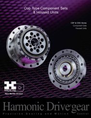
FHA-C Series - Harmonic Drive LLC
FHA-C Series - Harmonic Drive LLC
FHA-C Series - Harmonic Drive LLC
- No tags were found...

You also want an ePaper? Increase the reach of your titles
YUMPU automatically turns print PDFs into web optimized ePapers that Google loves.
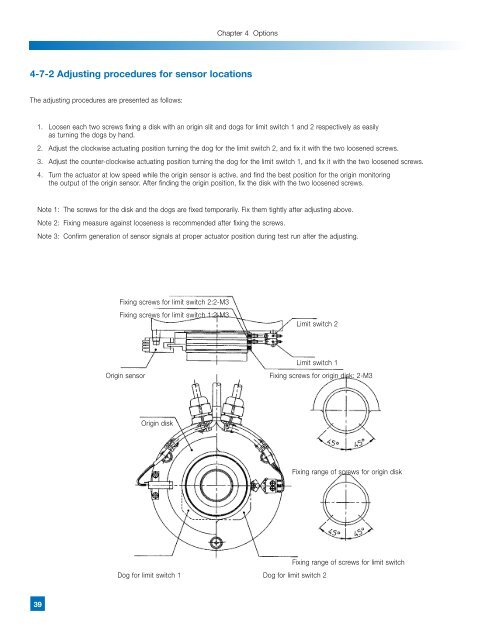
Chapter 4 Options4-7-2 Adjusting procedures for sensor locationsThe adjusting procedures are presented as follows:1. Loosen each two screws fixing a disk with an origin slit and dogs for limit switch 1 and 2 respectively as easilyas turning the dogs by hand.2. Adjust the clockwise actuating position turning the dog for the limit switch 2, and fix it with the two loosened screws.3. Adjust the counter-clockwise actuating position turning the dog for the limit switch 1, and fix it with the two loosened screws.4. Turn the actuator at low speed while the origin sensor is active, and find the best position for the origin monitoringthe output of the origin sensor. After finding the origin position, fix the disk with the two loosened screws.Note 1: The screws for the disk and the dogs are fixed temporarily. Fix them tightly after adjusting above.Note 2: Fixing measure against looseness is recommended after fixing the screws.Note 3: Confirm generation of sensor signals at proper actuator position during test run after the adjusting.Fixing screws for limit switch 2:2-M3Fixing screws for limit switch 1:2-M3Limit switch 2Limit switch 1Origin sensor Fixing screws for origin disk: 2-M3Origin diskFixing range of screws for origin diskFixing range of screws for limit switchDog for limit switch 1 Dog for limit switch 239