FHA-C Series - Harmonic Drive LLC
FHA-C Series - Harmonic Drive LLC
FHA-C Series - Harmonic Drive LLC
- No tags were found...

You also want an ePaper? Increase the reach of your titles
YUMPU automatically turns print PDFs into web optimized ePapers that Google loves.
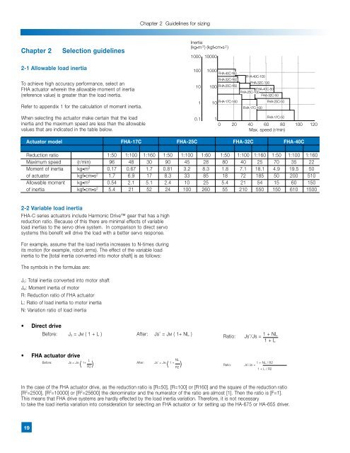
Chapter 2 Guidelines for sizingChapter 2Selection guidelinesInertia2(kg•m ) (kgf•cm•s 2)1000 100002-1 Allowable load inertiaTo achieve high accuracy performance, select an<strong>FHA</strong> actuator wherein the allowable moment of inertia(reference value) is greater than the load inertia.Refer to appendix 1 for the calculation of moment inertia.When selecting the actuator make certain that the loadinertia and the maximum speed are less than the allowablevalues that are indicated in the table below.100 1000<strong>FHA</strong>-40C-160<strong>FHA</strong>-32C-16010 100 <strong>FHA</strong>-25C-1601 10 <strong>FHA</strong>-17C-160<strong>FHA</strong>-40C-100<strong>FHA</strong>-32C-100<strong>FHA</strong>-40C-50<strong>FHA</strong>-25C-100<strong>FHA</strong>-32C-50<strong>FHA</strong>-17C-100<strong>FHA</strong>-25C-50<strong>FHA</strong>-17C-500.1 10 20 40 60 80 100 120Max. speed (r/min)Actuator model <strong>FHA</strong>-17C <strong>FHA</strong>-25C <strong>FHA</strong>-32C <strong>FHA</strong>-40CReduction ratio 1:50 1:100 1:160 1:50 1:100 1:60 1:50 1:100 1:160 1:50 1:100 1:160Maximum speed (r/min) 96 48 30 90 45 28 80 40 25 70 35 22Moment of inertia kg•m 2 0.17 0.67 1.7 0.81 3.2 8.3 1.8 7.1 18.1 4.9 19.5 50of actuator kgf•cm•s 2 1.7 6.9 17 8.3 33 85 18 72 185 50 200 510Allowable moment kg•m 2 0.54 2.1 5.1 2.4 10 25 5.4 21 54 15 60 150of inertia kgf•cm•s 2 5.4 21 52 24 100 260 55 210 550 150 610 15002-2 Variable load inertia<strong>FHA</strong>-C series actuators include <strong>Harmonic</strong> <strong>Drive</strong> gear that has a highreduction ratio. Because of this there are minimal effects of variableload inertias to the servo drive system. In comparison to direct servosystems this benefit will drive the load with a better servo response.For example, assume that the load inertia increases to N-times duringits motion (for example, robot arms). The effect of the variable loadinertia to the [total inertia converted into motor shaft] is as follows:The symbols in the formulas are:J S : Total inertia converted into motor shaftJ M : Moment inertia of motorR: Reduction ratio of <strong>FHA</strong> actuatorL: Ratio of load inertia to motor inertiaN: Variation ratio of load inertia• Direct driveBefore: J S = Jm ( 1 + L ) After: Js’ = Jm ( 1+ NL )Ratio:Js’/Js = 1 + NL1 + L• <strong>FHA</strong> actuator driveBefore: Js = Jm( 1+ L ) After: Js’ = Jm ( 1 + NL ) Ratio: Js’/Js =R2R21 + NL / R21 + L / R2In the case of the <strong>FHA</strong> actuator drive, as the reduction ratio is [R=50], [R=100] or [R160] and the square of the reduction ratio[R 2 =2500], [R 2 =10000] or [R 2 =25600] the denominator and the numerator of the ratio are almost [1]. Then the ratio is [F=1].This means that <strong>FHA</strong> drive systems are hardly effected by the load inertia variation. Therefore, it is not necessaryto take the load inertia variation into consideration for selecting an <strong>FHA</strong> actuator or for setting up the HA-675 or HA-655 driver.19