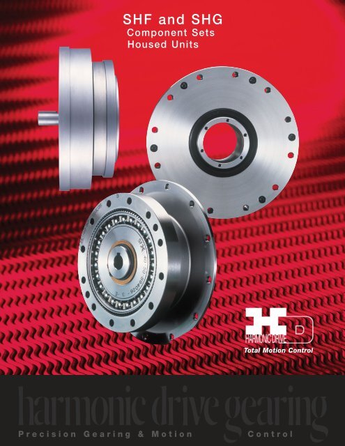
SHF and SHG - Harmonic Drive LLC
SHF and SHG - Harmonic Drive LLC
SHF and SHG - Harmonic Drive LLC

Create successful ePaper yourself
Turn your PDF publications into a flip-book with our unique Google optimized e-Paper software.
2<strong>SHF</strong> AND <strong>SHG</strong> HOUSED UNIT
ABOUT HARMONIC DRIVE GEARHEAD<strong>SHG</strong> 25 100 2UHSPORDERING CODENAME OF MODEL SIZE RATIO VERSION OPTION14 30,50,80,100, 2A-GR:Component Set17 30,50,80,100,120 (Size 14 &17 are 2A-R) Our application<strong>SHF</strong>: Silk Hat Type 20 30,50,80,100,120,160 2UH:Unit engineers will be(<strong>SHF</strong> series are available 25 30,50,80,100,120,160 with hollow input shaft <strong>and</strong> pleased to assistfor size 14-58) 32 30,50,80,100,120,160 integrated output bearing. you with special<strong>SHG</strong>: High-torque Type 40 50,80,100,120,160 2UJ:Unit options <strong>and</strong> their45 50,80,100,120,160 with solid input shaft <strong>and</strong> ordering code50 50,80,100,120,160 integrated output bearing58 50,80,100,120,160 250:Simple Unit: Flat type65 80,100,120,160 2SH:Simple Unit Flat Hollow Shaft typeEvolution of <strong>Harmonic</strong> <strong>Drive</strong> Gearing<strong>Harmonic</strong> drive gearing continues to evolve by improving performance <strong>and</strong> functionality.SSeriesBy pursuing strength<strong>and</strong> stiffness, a newtooth profile wasinvented. The "S"tooth doubled thetorque, life <strong>and</strong>stiffness.<strong>SHF</strong>To minimize the space, fora total cost reductionthe axial length hasbeen reduced to aboutone half. Unit thatallows easy mountingwas also available atthe same time.<strong>SHG</strong>The <strong>SHG</strong> achieved a 30% increase in torquecapacity. Life was increased from 7,000 hrsto 10,000 hrs.30:119881995The Ratio 30:1 was added for higheroutput speeds.Tooth ProfilesThe harmonic drive component sets <strong>and</strong> housed units presentedin this catalog incorporate the “S” gear tooth profile. This patentedtooth profile provides a significant improvement in gear operatingcharacteristics <strong>and</strong> performance.The new “S” tooth profile significantly increases the region oftooth engagement. For the traditional tooth profile 15% of thetotal number of teeth are in contact, while for the new profile up to30% of the teeth are in contact. The increased number of teeth inengagement results in a 100% increase in torsional stiffness in thelow & mid torque ranges.The new tooth profile also features an enlarged tooth root radius,which results in a higher allowable stress <strong>and</strong> a correspondingincrease in torque capacity. Furthermore, the enlarged regionof tooth engagement leads to a more even loading of the WaveGenerator bearing, resulting in more than double the life expectancyfor the gear.Initial EngagementFull Engagement4
PRINCIPLE AND STRUCTURESystem ComponentsThe FLEXSPLINE is a non-rigid, thin cylindrical steel cup with externalteeth on a slightly smaller pitch diameter than the Circular Spline.It fits over <strong>and</strong> is held in an elliptical shape by the Wave Generator.FlexsplineWave GeneratorThe WAVE GENERATOR is a thin raced ball bearing fitted onto an ellipticalplug serving as a high efficiency torque converter.The CIRCULAR SPLINE is a rigid ring with internal teeth, engaging theteeth of the Flexspline across the major axis of the Wave Generator.Circular Spline0 º90º 360ºCircular SplineWave GeneratorFlexsplineThe Flexspline is elliptically shaped by TheWave Generator <strong>and</strong> engaged with theCircular Spline at the major elliptical axis.The teeth completely disengage on theminor axis.When the Circular Spline is fixed <strong>and</strong>the Wave generator rotates clockwise,the Flexspline is elastically deformed<strong>and</strong> rotates counterclockwise relative tothe Circular Spline.For each 360 degrees clockwise movementof the Wave Generator,the Flexsplinemoves counterclockwise by two teethrelative to the Circular Spline.Circular SplineCircular SplineInputInputCross Roller BearingWave GeneratorFlexsplineCross Roller BearingWave GeneratorFlexsplineHollow Shaft Type (2UH)The <strong>SHF</strong> harmonic drive housed unit offers the design engineerconvenience <strong>and</strong> simplicity. The gears are contained within acompact housing, where the output flange is supported by a largediameter cross roller bearing. This provides exceptional momentstiffness with high radial <strong>and</strong> axial load capacity.Input Shaft Type (2UJ)The <strong>SHF</strong>-2UJ housed units have a different design for theinput. This series is driven via a solid shaft. These units, like the<strong>SHF</strong>-2UH models, integrate high capacity cross roller output bearingto provide a high permissible tilting moment as well as hightilting stiffness.Simplicity Unit Type (Option not shown)Flat type (2 SO) <strong>and</strong> Hollow Shaft type (2 SH) have been simplified by eliminatingInput <strong>and</strong> Output Flanges to achieve design flexibility <strong>and</strong> cost reduction.<strong>Harmonic</strong> <strong>Drive</strong> <strong>LLC</strong> 800-921-33325
DRIVING CONFIGURATIONSA variety of different driving configurations are possible, as shown below.The reduction ratio given in the tables on page 10 <strong>and</strong> 11 correspond to arrangement 1, in which the Wave Generatoracts as the input element, the Circular Spline is fixed <strong>and</strong> the Flexspline acts as the output element.1 2 3InputOutputFSCSWGGear Ratio =input speedoutput speed1. Reduction GearingCS FixedWG InputFS OutputRatio = R [Equation 1]-1Input <strong>and</strong> output in oppositedirection.1. Reduction GearingCS FixedWG InputFS OutputRatio = R+1 [Equation 2]1Input <strong>and</strong> output in oppositedirection.1. Reduction GearingCS FixedWG InputFS OutputRatio = R+1 [Equation 3]RInput <strong>and</strong> output in oppositedirection.4 5 6 71. Reduction GearingCS FixedWG InputFS OutputRatio = RR+1[Equation 4]Input <strong>and</strong> output in oppositedirection.1. Reduction GearingCS FixedWG InputFS OutputRatio = -R [Equation 5]1Input <strong>and</strong> output in oppositedirection.1. Reduction GearingCS FixedWG InputFS OutputRatio = R+1 [Equation 6]-1Input <strong>and</strong> output in oppositedirection.1. Differential GearingWG Control InputCS Main <strong>Drive</strong>-InputFS Main <strong>Drive</strong>-OutputNumerous differential functions canbe obtained by combinations of thespeed <strong>and</strong> rotational direction ofthe three basic elements.6
APPLICATION EXAMPLES<strong>SHF</strong> Series Application ExamplesApply <strong>SHF</strong>-2UH & <strong>SHF</strong>-2UJ to SCARA robotThe robot arm (Fig.1) is equipped with <strong>SHF</strong>-2UH <strong>and</strong> <strong>SHF</strong>-2UJ Series units.The hollow shaft of the first axis unit is used to pilot the shaft driving thesecond axis unit.This allows both motors to be mounted in the base ofthe robot, minimizing the moment of inertia of the arm.<strong>SHF</strong>-2UH<strong>SHF</strong>-2UJSecond Axis MotorFirst Axis Motor<strong>Harmonic</strong> <strong>Drive</strong> <strong>LLC</strong> 800-921-33327
APPLICATION EXAMPLES<strong>SHF</strong> Series Application ExamplesApply <strong>SHF</strong>-2UH & <strong>SHF</strong>-2UJ to Gantry robotThis robot h<strong>and</strong> axis design (Fig.2) incorporates both <strong>SHF</strong>-2UH <strong>and</strong> <strong>SHF</strong>-2UJ units.The second axis is driven through the hollow shaft of the first axis gear. This design hasnumber of advantages, including the compact design <strong>and</strong> low inertia for the second axis.Second Axis Input ShaftFirst Axis Input Shaft<strong>SHF</strong>-2UH<strong>SHF</strong>-2UJ8
APPLICATION EXAMPLES<strong>SHF</strong> Series Application ExamplesApply <strong>SHF</strong>-2SO to SCARA robotSpecially designed units are used in the robot arm featured in Fig.3.The particularly Simplicity units future <strong>SHF</strong>-2SO Component Sets combined with integral cross roller bearing,Circular Spline <strong>and</strong> Flexspline. It is important to note that the motor can be assembling from both sides of the unit.Circular SplineRingFlexsplineRingCross RollerBearingCircular SplineOil Seal DeletionThe Removable of the rotary shaftseal of <strong>SHF</strong>-2UHThe friction of the rotary shaft seals at the inputside can result in an increased temperature of the<strong>SHF</strong>-2UH unit during operation. This applicationexample (Fig.4) shows the removal of the (fast running)rotary shaft seals at the input side. The removal ofone or both rotary shaft seals at the input elementshould only be carried out if other measures havebeen undertaken to prevent the leakage of greaseor oil, or if a leakage can be ruled out due to theinstallation position.<strong>Harmonic</strong> <strong>Drive</strong> <strong>LLC</strong> 800-921-33329
<strong>SHG</strong> SERIES RATING TABLETable 1Size Ratio Rated Limit for Limit for Limit for Maximum Limit for MomentTorque Repeated Average Momentary Input Average ofat Peak Torque Peak Speed Input Inertia2000 Torque Torque SpeedT rrpm rpm rpmNm in-lb Nm in-lb Nm in-lb Nm in-lb Oil Grease Oil Grease x10 -4 kg•m 2 x10 -5 kgf•m•s 250 7 62 23 204 9 80 46 407 0.033 0.03414 80 10 89 30 266 14 124 61 540 14,000 8,500 6,500 3,500 (0.091) (0.093)100 10 89 36 319 14 124 70 620 (0.025) (0.026)50 21 186 44 389 34 301 91 805 0.079 0.0811780 29 257 56 496 35 310 113 1000 10,000 7,300 6,500 3,500 (0.193) (0.197)100 31 274 70 620 51 451 143 1266 (0.059) (0.060)120 31 274 70 620 51 451 112 99150 33 292 73 646 44 389 127 1124 0.193 0.19780 44 389 96 850 61 540 165 1460 (0.404) (0.412)20 100 52 460 107 947 64 566 191 1690 10,000 6,500 6,500 3,500 (0.137) (0.140)120 52 460 113 1000 64 566 191 1690160 52 460 120 1062 64 566 191 169050 51 451 127 1124 72 637 242 2142 0.413 0.42180 82 726 178 1575 113 1000 332 2938 (1.070) (1.090)25 100 87 770 204 1805 140 1239 369 3266 7,500 5,600 5,600 3,500 (0.320) (0.327)120 87 770 217 1920 140 1239 395 3496160 87 770 229 2027 140 1239 408 361150 99 876 281 2487 140 1239 497 4398 1.69 1.7280 153 1354 395 3496 217 1920 738 6531 (2.85) (2.91)32 100 178 1575 433 3832 281 2487 841 7443 7,000 4,800 4,600 3,500 (1.20) (1.22)120 178 1575 459 4062 281 2487 892 7894160 178 1575 484 4283 281 2487 892 789450 178 1575 523 4629 255 2257 892 789480 268 2372 675 5974 369 3266 1270 11240 4.50 4.5940 100 345 3053 738 6531 484 4283 1400 12390 5,600 4,000 3,600 3,000 (9.28) (9.47)120 382 3381 802 7098 586 5186 1530 13541 (3.41) (3.48)160 382 3381 841 7443 586 5186 1530 1354150 229 2027 650 5753 345 3053 1235 1093080 407 3602 918 8124 507 4487 1651 15611 8.68 8.8645 100 459 4062 982 8691 650 5753 2041 18063 5,000 3,800 3,300 3,000 (13.8) (14.1)120 523 4629 1070 9470 806 7133 2288 20249 (5.80) (5.92)160 523 4629 1147 10151 819 7248 2483 2197580 484 4283 1223 10824 675 5974 2418 21399 12.5 12.850100 611 5407 1274 11275 866 7664 2678 23700 4,500 3,500 3,000 2,500 (25.2) (25.7)120 688 6089 1404 12425 1057 9354 2678 23700 (9.95) (10.2)160 688 6089 1534 13576 1096 9700 3185 2818780 714 6319 1924 17027 1001 8859 3185 28187 27.3 27.95865100 905 8009 2067 18293 1378 12195 4134 36586 4,000 3,000 2,700 2,200 (49.5) (50.5)120 969 8576 2236 19789 1547 13691 4329 38312 (20.5) (20.9)160 969 8576 2392 21169 1573 13921 4459 3946280 969 8576 2743 24276 1352 11965 4836 42799100 1236 10939 2990 26462 1976 17488 6175 54649 46.5 47.8120 1236 10939 3263 28878 2041 18063 6175 54649 3,500 2,800 2,400 1,900 (94.1) (96.0)160 1236 10939 3419 30258 2041 18063 6175 54649 (35.5) (36.2)Note:1. The moment of inertia : I = 1/4 GD 2 , reflected to input side (wave generator).2. The value in parenthesis indicate unit type.Top: Component TypeMiddle: (Hollow Type 2UH)Bottom: (Shaft Type 2UJ)10
<strong>SHF</strong> SERIES RATING TABLETable 2Size Ratio Rated Limit for Limit for Limit for Maximum Limit for MomentTorque Repeated Average Momentary Input Average ofat Peak Torque Peak Speed Input Inertia2000 Torque Torque SpeedT rrpm rpm rpm I JNm in-lb Nm in-lb Nm in-lb Nm in-lb Oil Grease Oil Grease x10 -4 kg•m 2 x10 -5 kgf•m•s 230 4 35 9 80 6.8 60 17 150 0.033 0.03450 5.4 48 18 159 6.9 61 35 310 14,000 8,500 6,500 3,500 (0.091) (0.093)14 80 7.8 69 23 204 11 97 47 416 (0.025) (0.026)100 7.8 69 28 248 11 97 54 47830 8.8 78 16 142 12 106 30 26650 16 142 34 301 26 230 70 620 0.079 0.08117 80 22 195 43 381 27 239 87 770 10,000 7,300 6,500 3,500 (0.193) (0.197)100 24 212 54 478 39 345 110 974 (0.059) (0.060)120 24 212 54 478 39 345 86 76130 15 133 27 239 20 177 50 44350 25 221 56 469 34 301 98 867 0.193 0.19720 80 34 301 74 655 47 416 127 1124 (0.404) (0.412)100 40 354 82 726 49 434 147 1301 10,000 6,500 6,500 3,500 (0.137) (0.140)120 40 354 87 770 49 434 147 1301160 40 354 92 814 49 434 147 130130 27 239 50 443 38 336 95 84150 39 345 98 867 55 487 186 1646 0.413 0.42125 80 63 558 137 1212 87 770 255 2257 7,500 5,600 5,600 3,500 (1.070) (1.090)100 67 593 157 1389 108 956 284 2513 (0.320) (0.327)120 67 593 167 1478 108 956 304 2690160 67 593 176 1558 108 956 314 277930 54 478 100 885 75 664 200 177050 76 673 216 1912 108 956 382 3381 1.69 1.7232 80 118 1044 304 2690 167 1478 568 5027 7,000 4,800 4,600 3,500 (2.85) (2.91)100 137 1212 333 2947 216 1912 647 5726 (1.20) (1.22)120 137 1212 353 3124 216 1912 686 6071160 137 1212 372 3292 216 1912 686 607150 137 1212 402 3558 196 1735 686 607180 206 1823 519 4593 284 2513 980 8673 4.50 4.5940 100 265 2345 568 5027 372 3292 1080 9558 5,600 4,000 3,600 3,000 (9.28) (9.47)120 294 2602 617 5460 451 3991 1180 10443 (3.41) (3.48)160 294 2602 647 5726 451 3991 1180 1044350 176 1558 500 4425 265 2345 950 840880 313 2770 706 6248 390 3452 1270 11240 8.68 8.8645 100 353 3124 755 6682 500 4425 1570 13895 5,000 3,800 3,300 3,000 (13.8) (14.1)120 402 3558 823 7284 620 5487 1760 15576 (5.80) (5.92)160 402 3558 882 7806 630 5576 1910 1690450 245 2168 715 6328 350 3098 1430 1265680 372 3292 941 8328 519 4593 1860 16461 12.5 12.850 100 470 4160 980 8673 666 5894 2060 18231 4,500 3,500 3,000 2,500 (25.2) (25.7)120 529 4682 1080 9558 813 7195 2060 18231 (9.95) (10.2)160 529 4682 1180 10443 843 7461 2450 2168350 353 3124 1020 9027 520 4602 1960 1734680 549 4859 1480 13098 770 6815 2450 21683 27.3 27.958100 696 6160 1590 14072 1060 9381 3180 28143 4,000 3,000 2,700 2,200 (49.5) (50.5)120 745 6593 1720 15222 1190 10532 3330 29471 (20.5) (20.9)160 745 6593 1840 16284 1210 10709 3430 30356Note:1. Component type in sizes 50 <strong>and</strong> over with gear ratio 50:1 use oil lubrication.If it is necessary to use grease, the rated torque is reduced by 50%.2. The moment of inertia : 1=1/4 GD 2 , reflected to input side (wave generator).3. The value in parenthesis indicates unit type.Top: Component typeMiddle: (Hollow Type 2UH)Bottom: (Shaft Type 2UJ)<strong>Harmonic</strong> <strong>Drive</strong> <strong>LLC</strong> 800-921-333211
TECHNICAL TERMSDefinition of RatingsRated Torque (Tr)Rated torque indicates allowable continuous loadtorque at 2000 rpm input speed.Limit for Repeated Peak Torque (refer to figure 1)During acceleration a deceleration the harmonic drive gear experiencesa peak torque as a result of the moment ofinertia of the output load.Limit for Average TorqueIn cases where load torque <strong>and</strong> input speed vary, it is necessaryto calculate an average value of load torque. The table indicatesthe limit for average torque. The average torque calculatedmust not exceed this limit.Limit for Momentary Peak Torque(refer to figure 1)<strong>Harmonic</strong> drive gearing may be subjected to momentary peaktorques in the event of a collision or emergency stop. Themagnitude <strong>and</strong> frequency of occurrence of such peak torquesmust be kept to a minimum <strong>and</strong> they should, under nocircumstance, occur during normal operating cycle. The allowablenumber of occurrences of the momentary peaktorque may be calculated by using equation 1 on page 12.Also see section “strength <strong>and</strong> life”.Figure 1Abnormal Impact TorqueStrength <strong>and</strong> LifeThe non-rigid Flexspline is subjected to repeated deflections,<strong>and</strong> its strength determines the torque capacity of the harmonicdrive gear. The values given for Rated Torque at Rated Speed<strong>and</strong> for the allowable Repeated Peak Torque are based on aninfinite fatigue life for the Flexspline.The torque that occurs during a collision must be below themomentary peak torque (impact torque). The maximum numberof occurrences is given by the equation below.[Equation 1]N = ____________1.0 X 10 4 n: Input speed before collision2 X n X t t: Time interval during collision60Please note:If this number is exceeded, the Flexspline may experiencea fatigue failure.Ratcheting phenomenonWhen excessive torque is applied while the harmonic drivegear is in motion, the teeth between the Circular Spline <strong>and</strong>Flexspline may not engage properly. This phenomenon iscalled ratcheting <strong>and</strong> the torque at which this occurs is calledratcheting torque. Ratcheting may cause the Flexspline to becomenon-concentric with the Circular Spline.(See figure 1 & 2 on page 12) Operating in this conditionmay result in shortened life <strong>and</strong> a Flexspline fatigue failure.Figure 2StartRoutineLoad TorqueNumber of Rotationsof Wave GeneratorStopSpeed CycleStartTimeLoad TorqueTimeRepeated Peak TorqueMomentary Peak TorqueCircular SplineFlexsplineThis condition is called “dedoidal”.Maximum Input Speed,Limit for average input speedDo not exceed the allowable rating.Moment of InertiaThe rating indicates the moment of inertia reflected to thewave generator (gear input).Note!When ratcheting occurs, the teeth mesh abnormallyas shown above.Vibration <strong>and</strong> Flexspline damage may occur.Once ratcheting occurs, the teeth wear excessively <strong>and</strong> theratcheting torque may be lowered.12
TECHNICAL TERMS<strong>SHF</strong> Ratcheting Torque Table3 NmSizeRatio30 50 80 100 120 16014 59 88 110 84 - -17 100 150 200 160 120 -20 170 220 350 260 240 22025 340 450 680 500 470 45032 720 980 1400 1000 980 98040 - 1800 2800 2100 1900 180045 - 2700 3900 3100 2800 260050 - 3700 5400 4100 3800 360058 - 5800 8200 6400 5800 5600Table 4Nm<strong>SHF</strong> Buckling TorqueSizeAll Ratio14 19017 33020 56025 100032 220040 430045 580050 800058 12000<strong>SHG</strong> Ratcheting Torque Table 5 NmSizeRatio50 80 100 120 16014 110 140 100 - -17 190 260 200 150 -20 280 450 330 310 28025 580 880 650 610 58032 1200 1800 1300 1200 120040 2300 3600 2700 2400 230045 3500 5000 4000 3600 330050 – 7000 5300 4900 460058 – 10000 8300 7500 720065 – 14000 12000 10000 10000Table 6Nm<strong>SHG</strong> Buckling TorqueSizeAll Ratio14 21017 42020 70025 130032 280040 520045 760050 1040058 1620065 22800The Life of a Wave GeneratorThe normal life of a harmonic drive gear is determined by thelife of the wave generator bearing. The life may be calculatedby using the input speed <strong>and</strong> the output load torque.Rated Lifetime L n: (n = 10 or 50)L 10<strong>SHF</strong> : 7,000 <strong>SHG</strong>: 10,000L 50<strong>SHF</strong> : 35,000 <strong>SHG</strong> : 50,000Relative Torque RatingThe chart below shows the various torque specificationsrelative to rated torque. Rated Torque has beennormalized to 1 for comparison.Equation for the expected life of the wave generator undernormal operating conditions is given by the equation below.1716Figure 3Buckling Torque[Equation 2]Lh = Ln • ( Tr ) 3 • ( Nr )Tav NavLh : Expected Life, hoursLn : Rated Lifetime at L 10or L 50Tr : Rated Torque (Tables 1, 2, 3)Nr : Rated input speed (2000 rpm)Tav : Average load torque on output side (page 14)Nav : Average input speed (page 14)Load Torque ( Rated Torque = 1 )109Racheting Torque87Life of the Wave Generator, L1065Fatigue Strength of Flexspline4Momentary Peak Torque32 Repeated Peak Torque1Rated Torque0 10 5 10 6 10 7 10 8 10 9Total Number of Input Rotations10 10<strong>Harmonic</strong> <strong>Drive</strong> <strong>LLC</strong> 800-921-333213
SELECTION PROCEDURESize SelectionGenerally, the operating conditions consist of fluctuating torques<strong>and</strong> output speeds. Also, an unexpected impact output torquemust be considered.The proper size can be determined by converting fluctuating loadtorque into average load torque <strong>and</strong> equivalent load torque. Thisprocedure involves selecting the size based on load torque forcomponent sets.This procedure does not consider the life of the output bearingfor housed units. Determining the life of the output bearing forvarious axial, radial, <strong>and</strong> moment loads is outlined on page 31.Flow Chart for selecting a sizePlease use the flowchart shown below for selecting a size.Operating conditions must not exceed the performanceratings as described on page 12.Calculation of the average output torqueTav = 3 n 1•t 1•|T 1| 3 +n 2•t 2•|T 2| 3 +... nn•tn•|Tn| 3n 1•t 1+n 2•t 2+... n nt nSelection of tentative size under thecondition shown below.Figure 4+T 1T nAverage Output Speedno av = n 1 •t 1 •n 2 •t 2 +... n n t nt1+t2•t2+...tnTorque_T 2T 4T 3t 1 t 2 t 3 t 4 t nn 2TimeDetermine Gear Ration imax
SELECTION PROCEDUREValues of an each Load Torque PatternLoad Torque Tn (Nm) no max = 14 rpmTime tn (sec) ni max = 1800 rpmOutput Speednn (rpm)Normal Operating PatternAcceleration T1 = 400 Nm, t1 = 0.3 sec, n1 = 7 rpm Ts = 500 Nm, ts = 0.15 sec, ns = 14 rpmRegular Operation Stop T2 = 320 Nm, t2 = 3 sec, n2 = 14 rpmDeceleration T3 = 200 Nm, t3 = 0.4 sec, n3 = 7 rpm L10 = 7000 hrs.Dwell T4 = 0 Nm, t4 = 0.2 sec, n4 = 0 rpm Oil LubricationTav (Nm)3 7rpm•0.3sec•|400Nm| 3 +14rpm•3sec•|320Nm| 3 +7rpm•0.4sec•|200Nm| 3Tav =7rpm•0.3sec+14rpm•3sec+7rpm•0.4secTav =319Nm 12014 rpmn i av = 12 rpm •120 = 1440 rpmn o max ni max (rpm)n i max = 14 rpm •120 = 1680 rpmniav =1440rpm
DIMENSION AND SHAPEBC1C2EFL - øMøZ1Db0W JS9A2 - N2 - øPeH2øTøI h6øJ H6øaødøK h6øU2C0.4øV H7øU1øaøA h6+0.10XøQGNo key on WG hub for #14 <strong>and</strong> #17C0.4YR0.3C0.4C0.4 C0.4 cH 01-0.1C0.4R - øSDetail drawings are also availableøZ22.5 (size14) 3 (size17)2-M3X6 (size14)2-M3X6 (size17)W AVE GENERATOR COMPONENTS12 3There is a difference of the ball separatorbetween <strong>SHF</strong> <strong>and</strong> <strong>SHG</strong>.(<strong>SHG</strong> size 14 <strong>and</strong> 17 use the sameball separator as <strong>SHF</strong>)1. Ball SeparatorH22. Wave Generator Bearing3. Wave Generator Plug4. Insert5. Rub Washer6. Snap RingøU2<strong>SHF</strong> ALL SIZES<strong>SHG</strong> - 14, 17, 657. Wave Generator Hub4 5 6 7<strong>SHF</strong>-14,17,20,25,32,45,58<strong>SHF</strong>-40,50,65<strong>SHG</strong>-20 AND ABOVE16
EXTERNAL DIMENSIONSTable 7BGH 114 17 20 25 32 40 45 50 58 65øA h6 50 60 70 85 110 135 155 170 195 215<strong>SHF</strong> 28.5 0 -0.832.5 0 -0.933.5 0 -1.037 0 -1.044 0 -1.153 0 -1.158.5 0 -1.264 0 -1.375.5 0 -1.3–<strong>SHG</strong> 28.5 0 -0.432.5 0 -0.433.5 0 -0.437 0 -0.544 0 -0.653 0 -0.658.5 0 -0.664 0 -0.775.5 0 -0.783 0 -0.7C 117.5 +0.4 020+0.5 021.5 +0.8 024+0.8 028+0.8 034 +0.6 038 +0.6 041+0.6 048+0.6 052.5+0.6 0C 211 12.5 12 13 16 19 20.5 23 27.5 30.5D 2.4 3 3 3.3 3.6 4 4.5 5 5.8 6.5E 2 2.5 3 3 3 4 4 4 5 5F 6 6.5 7.5 10 14 17 19 22 25 29<strong>SHF</strong> 0.4 0.3 0.1 2.1 2.5 3.3 3.7 4.2 4.8 –<strong>SHG</strong> 1.4 1.6 1.5 3.5 4.2 5.6 6.3 7 8.2 9.5<strong>SHF</strong> 17.6 0 -0.119.5 0 -0.120.1 0 -0.120.2 0 -0.122 0 -0.127.5 0 -0.127.9 0 -0.132 0 -0.134.9 0 -0.1–<strong>SHG</strong> 18.5 0 -0.120.7 0 -0.121.5 0 -0.121.6 0 -0.123.6 0 -0.129.7 0 -0.130.5 0 -0.134.8 0 -0.138.3 0 -0.144.6 0 -0.1H 2– – – – – 0.4 – 0.8 – 2.2<strong>SHF</strong> øI h660 72 82 104 134 164 182 205 233 –<strong>SHG</strong> 60 72 82 104 134 164 190 214 240 276øJ H6 48 60 70 88 114 140 158 175 203 2321/30 38 48 54 67 90 110 124 135 156 177øKh6 1/30 38 48 55 68 90 – – – – –L 8 12 12 12 12 12 18 12 16 16RTøVøM 3.5 3.5 3.5 4.5 5.5 6.6 6.6 9 9 11N M3 M3 M3 M4 M5 M6 M8 M8 M10 M10O 6 6.5 4 6 7 9 12 13 15 15øP – – 3.5 4.5 5.5 6.6 9 9 11 11Q 44 54 62 75 100 120 140 150 175 195<strong>SHF</strong> 6 12 12 12 12 12 12 12 12 –<strong>SHG</strong> 8 16 16 16 16 16 16 16 16 16øS 3.5 3.5 3.5 4.5 5.5 6.6 9 9 11 11<strong>SHF</strong> 54 66 76 96 124 152 170 190 218 –<strong>SHG</strong> 54 66 76 96 124 152 180 200 226 258øU 114 18 21 26 26 32 32 32 40 48øU 2– – – – – 32 – 32 – 48(H7) st<strong>and</strong>ard 6 8 9 11 14 14 19 19 22 24maximum 8 10 13 15 15 20 20 20 25 30WJs9 – – 3 4 5 5 6 6 6 8X – – 10.4+0.1 012.8+0.1 016.3+0.1 016.3+0.1 021.8+0.1 021.8+0.1 024.8+0.1 027.3+0.2 0Y C0.3 C0.4 C0.4 C0.4 C0.4 C0.4 C0.4 C0.8 C0.8 C0.8øZ 10.25 0.25 0.25 0.25 0.25 0.3 0.3 0.5 0.5 0.5øZ 20.25 0.25 0.25 0.25 0.25 0.3 0.5 0.5 0.5 0.5øa 38 45 53 66 86 106 119 133 154 172b 14.6 16.4 17.8 19.8 23.2 28.6 31.9 34.2 40.1 43c 1 1 1.5 1.5 1.5 2 2 2 2.5 2.5ød 31 38 45 56 73 90 101 113 131 150e 1.7 2.1 2.0 2.0 2.0 2.0 2.3 2.5 2.9 3.5Weight (kg) 0.11 0.18 0.31 0.48 0.97 1.87 2.64 3.53 5.17 7.04Component Type• Installed surface on Circular Spline is shown as (A). Use this surface for installation in Case.• Dimensions shown below maybe modified as a special order.Wave Generator : VFlexspline : L <strong>and</strong> MCircular Spline : R <strong>and</strong> S• Dimensions for B, C 1, C 2must meet the tolerance values shown above.• Due to the deformation of the Flexspline during operation, it is necessary to provide a minimum housing clearance.(Dimensions Øa to e)(mm)<strong>Harmonic</strong> <strong>Drive</strong> <strong>LLC</strong> 800-921-333217
LUBRICATIONRecommended Dimensionsfor Inner CaseMaximum centering lengthRecommended dimensions for inner case must meetwith numbers shown below. These dimensions mustbe maintained to prevent damage to the gear <strong>and</strong> tomaintain a proper grease cavity.Countersink for bolthead of circular splineRecommended Dimensions for Inner Case Table 8 Unit: mmSize 14 17 20 25 32 40 45 50 58 65øa 38 45 53 66 86 106 119 133 154 172b 14.6 16.4 17.8 19.8 23.2 28.6 31.9 34.2 40.1 43c 1(3) 1(3) 1.5(4.5) 1.5(4.5) 1.5(4.5) 2(6) 2(6) 2(6) 2.5(7.5) 2.5(7.5)ød 31 38 45 56 73 90 101 113 131 150e 1.7 2.1 2.0 2.0 2.0 2.0 2.3 2.5 2.9 3.5øf 16 26 30 37 37 45 45 45 56 62Note: Values in parenthesis show the value when the Wave Generator is pointing up.Flexspline1. Fill the tooth space with grease.Wave generator1. Fill cavity between retainer <strong>and</strong>bearing with grease.Circular SplineInput Cover(Motor Flange)2. Diameter ofball bearing.3.Apply grease to inner surface inaccordance with value shown above.Fill the toothspace with grease.4.Apply thin coat to avoid corrosion.2. Apply grease to oldham coupling.Fill cavitywith greaseNote: Fill cavity between Wave Generator <strong>and</strong> Input Cover (Motor Flange) with grease, when the Wave Generator is used for vertical installation. (page 21, Figure 3)Grease Usage Table 9 Unit: gSize 14 17 20 25 32 40 45 50 58 65amount 5.5 10 16 40 60 130 180 260 360 460<strong>Harmonic</strong> <strong>Drive</strong> <strong>LLC</strong> 800-921-333219
LUBRICATIONGrease ChangeThe wear characteristics of harmonic drive gearing are strongly influencedby the condition of the grease lubrication. The condition of thegrease is affected by the ambient temperature. The graphshows the maximum number of input rotations for various temperatures.This graph applies to applications where the average load torquedoes not exceed the rated torque.In cases where the rated torque is exceeded, calculate the greasechange interval using the equation shown below.Equation where average load torque exceeds rated torque[Equation 3]L GT= L GTnX ( Tr ) 3TavSymbol of EquationGrease change (over rated torque), input rotationsL GTL GTnT rT avGrease change (below rated torque), input rotations (From Graph)Rated TorqueAverage load torque on outputNumber of Rotations10 10Grease Change Interval for Tav < Tr LGTnGrease Life4B No.210 9SK-1ASK-210 8Wave Generator Life10 720 40 60 80 100 120Grease Temperature (Cº)20
LUBRICATIONOil LubricantKind of LubricantName of Lubricant Table 10Industrial Mobil Exxon Showa Shell Cosmo Japan Energy Shin Nippon Oil Idemitsu Kosan General oil NOK KrewbaIndustrial Gear Mobil Spartan Omara Cosmo ES Bon nock Dafuni General Oil Shin tessoOil#2 ISO VG68 gear 626 EP68 oil 68 gear SE68 gear G68 AX68 Supergear LW68 SP gear Roll 68 DE-68 EP(extreme pressure)M68Oil Level of Horizontal Usage Table 11mmSize 14 17 20 25 32 40 45 50 58 65A 10 12 14 17 24 31 35 38 44 50Horizontal Installation:Oil level should be maintained at the level “A” as shown.Oil Level for Horizontal UsageOil LevelOil Level of Vertical Usage Table 12mmSize 14 17 20 25 32 40 45 50 58 65B 2.5 3 3 5 7 9 10 12 13 15Vertical Installation:If the input shaft is on top, lube holes are provided on the bossof the Flexspline to facilitate the flow of oil inside the Flexsplinecup. The lube holes serve as breathers if the component set isused with input down.When the harmonic drive gear is to be used vertically with theWave Generator placed at the bottom, special considerationmust be given. If the Wave Generator assembly is completelysubmerged in oil, the heat generation caused by churning oilwill be substantial <strong>and</strong> a loss of efficiency will result. It isrecommended that the oil level be maintained in such a waythat approximately one half of the Wave Generator Bearing issubmerged.Oil level should be maintained at the level “B” shown.To ensure a sufficient amount of lubricant it may be necessaryto extend the bottom area of the housing or to provide an externaloil reservoir. A forced lubrication system may also be considered.Oil LevelOil LevelOutput on TopOil Level of Vertical UsageOutput on Bottom<strong>Harmonic</strong> <strong>Drive</strong> <strong>LLC</strong> 800-921-333221
LUBRICATIONExample of Oil Channeling to the Flexspline Interface.When oil is used as lubrication, the flange connected to the Flexspline must have a passage for oil to flow through.This allows for proper oil circulation. (Refer to Figure 4)Oil Quantity Table 13mmSize 14 17 20 25 32 40 45 50 58 65Amount 0.01 0.02 0.03 0.07 0.13 0.25 0.32 0.4 0.7 1.0Oil Change• The first oil change should be performed after 100 hours of operation.• The need to perform subsequent oil changes will depend on operating conditions,but should take place at intervals of approximately 1000 running hours.Other notes: Avoid mixing different kinds of oil. <strong>Harmonic</strong> drive gearing should be in an individual case when installed.Special Lubricants for Extreme TemperaturesIn extreme temperature environments (Exceptions are shown on page 18), please consider the following lubricanttemperature range <strong>and</strong> condition, <strong>and</strong> select type of lubricant.<strong>Harmonic</strong> Grease 4B No.2Lubricant St<strong>and</strong>ard Temperature Possible Temperaturegrease -10ºC~+110ºC -50ºC~+130ºCHigh Temperature LubricantLubricant Name <strong>and</strong> Manufacturer Possible TemperatureMobil Grease 28 Mobil Grease 28 -5ºC~+160ºCOil Mobil SHC-626 -5ºC~+140ºCLow Temperature LubricantLubricant Name & Manufacturer Possible Temperaturegrease Multemp SH-K11 Kyodo Yushi -30ºC~+50ºCIso Flex LDS-18 special A NOK krewba -25ºC~+80ºCoil SH-200-100CS Tore Silicon -40ºC~+140ºCShintesso D-32EP:NOK krewba -25ºC~+90ºC1. St<strong>and</strong>ard temperature range is harmonic grease 4B No.2is the grease temperature during operation.This grease has been developed for improved performance of harmonic drive gearing.2. Possible temperature range indicates temperature of individual lubricant.It will cause restriction on operating condition (Rated torque, In-put <strong>and</strong> Out-put speed <strong>and</strong> operating cycle etc.,).If ambient temperature is lowest or highest temperature, it is necessary to change the materials, please contact us.3. The temperature range of the grease can be extended as indicated in the possible temperature range shown.At the low end of this range the efficiency will be low due to an increase in viscosity of the lubricant.At the high end of this range the lubricant life will be low due to an increased deterioration rate from the high temperature.22
RECOMMENDED TOLERANCES FOR ASSEMBLYFor peak performance of the <strong>SHF</strong> Component Set it is essential that the following tolerances be observed when assembly is complete.Recommended tolerances for assemblyAttached Surfaced ACircular Spline Interfacea AARecommended Housing Tolerance H7BAttached Surfacee BWave Generator Interfacef BøcAøgBRecommended Shaft Tolerance h6Recommended Shaft Tolerance h6bAFlexspline InterfaceTolerances for Assembly Table 14unit:mmSize 14 17 20 25 32 40 45 50 58 65a 0.011 0.012 0.013 0.014 0.016 0.016 0.017 0.018 0.020 0.023b 0.016 0.021 0.027 0.035 0.042 0.048 0.053 0.057 0.062 0.067øc 0.015 0.018 0.019 0.022 0.022 0.024 0.027 0.030 0.032 0.035d 0.011 0.015 0.017 0.024 0.026 0.026 0.027 0.028 0.031 0.034e 0.011 0.015 0.017 0.024 0.026 0.026 0.027 0.028 0.031 0.034f 0.017 0.020 0.024 0.024 0.024 0.032 0.032 0.032 0.032 0.032(0.008) (0.010) (0.012) (0.012) (0.012) (0.012) (0.013) (0.015) (0.015) (0.015)øg 0.030 0.034 0.044 0.047 0.050 0.063 0.065 0.066 0.068 0.070(0.016) (0.018) (0.019) (0.022) (0.022) (0.024) (0.027) (0.030) (0.033) (0.035)The values in parentheses indicate that Wave Generator does not have an Oldham coupling.Sealing structureA seal structure is needed to maintain the high durability of harmonic drive gearing <strong>and</strong> prevent grease leakage.Key Points to Verify• Rotating parts should have an oil seal (with spring), surface should be smooth (no scratches)• Mating flanges should have an O Ring, seal adhesive• Screws should have a thread lock(Loctite 242 recommended) or seal adhesive.(note)If you use <strong>Harmonic</strong> grease 4BNo.2, strict sealing is required.<strong>Harmonic</strong> <strong>Drive</strong> <strong>LLC</strong> 800-921-333223
DIAMETERSHole Diameter of Wave generator Hub Table 15 Unit: mmSize 14 17 20 25 32 40 45 50 58 65St<strong>and</strong>ard Dimension 6 8 9 11 14 14 19 19 22 24Minimum Hole Dimension 3 4 5 6 6 10 10 10 13 16Maximum Hole Dimension 8 10 13 15 15 20 20 20 25 30Hole Diameter of Wave GeneratorHøV'Installation of Three Basic ElementsInstallation for Wave Generator <strong>and</strong> the maximum hole dimensions.Shown above is the st<strong>and</strong>ard hole dimension of the Wave Generatorfor each size. The dimension can be changed within a range up tothe maximum hole dimension shown in table 15. We recommend thedimension of keyway based on JIS st<strong>and</strong>ard. It is necessary that thedimension of keyways should sustain the transmission torque.Please note: Tapered holes are also available.In cases where a larger hole is required, use the Wave Generator withoutthe Oldham coupling. The maximum diameter of the hole shouldbe consideredto prevent deformation of the Wave Generator plug by load torque.The dimension is shown in table 16 include the dimension ofdepth of keyway.Maximum Diameter or Hole without Coupling Table 16 Unit: mmSize 14 17 20 25 32 40 45 50 58 65Maximum Diameter øV’ 17 20 23 28 36 42 47 52 60 67Min. Thickness of Plug H 7.2 7.6 11.3 11.3 13.7 15.9 17.8 19 21.4 13.5Direction for Thrust Force of WaveGeneratorAxial Force of Wave GeneratorWhen a harmonic drive gear is used to accelerate a load, the deflection ofthe Flexspline leads to an axial force acting on the Wave Generator. Thisaxial force, which acts in the direction of the closed end of the Flexspline,must be supported by the bearings of the input shaft (motor shaft).When a harmonic drive gear is used to decelerate a load, an axial force actsto push the Wave Generator out of the Flexspline cup. Maximum axial forceof the Wave Generator can be calculated by the equation shown below.The axial force may vary depending on its operating condition. The value ofaxial force tends to be a larger number when using high torque, extreme lowspeed <strong>and</strong> constant operation. The force is calculated (approximately) bythe equation. In all cases, the Wave Generator must be axially (in both directions),as well as torsionally, fixed to the input shaft.Equation for axial force equation 3Gear Ratioequationi=1/30 F=2x T x 0.07 x tan 32ºDi=1/50 F=2x T x 0.07 x tan 30ºDi=1/80 <strong>and</strong> up F=2x T x 0.07 x tan 20ºDSymbols for equationF axial force ND HD Size x 0.00254 mT output torque Nm(note) Please contact us when you fix the Wave Generator hub <strong>and</strong> inputshaft using bolts.Calculation Examplesize : 32Ratio : i=1/50Output Torque : 300NmF=2x 300 x 0.07xtan 30º(32x0.00254)F=298N24
ASSEMBLY OF THE FLEXSPLINEShape <strong>and</strong> dimension of Wave GeneratorThere is a difference between <strong>SHF</strong> series <strong>and</strong> <strong>SHG</strong> series with regard to the shape <strong>and</strong> dimension of the Wave Generator.Table 17 <strong>and</strong> Figure 5 show the comparison of the shape <strong>and</strong> dimension for the Wave Generator.During design <strong>and</strong> installation, please ensure there is no interference between the bolt of the Wave Generator <strong>and</strong> Flexspline.Comparison of Dimension of Wave Generator Hub Table 17 Unit: mmSize 14 17 20 25 32 40 45 50 58 65G<strong>SHF</strong> 0.4 0.3 0.1 2.1 2.5 3.3 3.7 4.2 4.8 –<strong>SHG</strong> 1.4 1.6 1.5 3.5 4.2 5.6 6.3 7 8.2 9.5H 1 <strong>SHF</strong> 17.6 0 -0.119.5 0 -0.120.1 0 -0.120.2 0 -0.122 0 -0.127.5 0 -0.127.9 0 -0.132 0 -0.134.9 0 -0.1–<strong>SHG</strong> 18.5 0 -0.120.7 0 -0.121.5 0 -0.121.6 0 -0.123.6 0 -0.129.7 0 -0.130.5 0 -0.134.8 0 -0.138.3 0 -0.144.6 0 -0.1Figure 5. Comparison of shape for Wave GeneratorH1Installation of flexsplineFor installation, the flange diameter should not exceed the bossdiameter of Flexspline shown on figure 5. The flange which contactsthe diaphragm should have radius, R. A large diameter <strong>and</strong> flangewithout a radius may cause damage to the diaphragm.G<strong>SHF</strong> SeriesG<strong>SHG</strong> SeriesH1Comparison of Dimension of Flexspline Table 18Size 14 17 20 25 32 40 45 50 58 65øD 48 60 70 88 114 140 158 175 203 232Figure 6. Installation for FlexsplineRecommended Dimension for Flange for InstallationDiaphram Avoid Avoid<strong>Harmonic</strong> <strong>Drive</strong> <strong>LLC</strong> 800-921-333225
INSTALLATION PROCEDUREInstallation of the FlexsplineThe load is normally attached to the Flexspline using a boltor screw. For high load torques dowel pins can be used inaddition to bolts or screws.The strength of the selected bolt, clamp torque, surfacecondition of bolt <strong>and</strong> thread, <strong>and</strong> coefficient of friction onthe contact surface are important factors to consider.To determine transmission torque of the fastened partconsider conditions indicated above.Please fasten bolts with the proper torque for each sizeas indicated. Please use the table shown below todecide if dowel pins are needed.1. If the load torque is less than momentary peak torque shownon tables 1 <strong>and</strong> 2 then only bolts are needed.2. If the load torque is expected to reach momentary peak torque,both bolts <strong>and</strong> pins should be used.Use values on the list as a reference.Tables 19, 21 pertain to the <strong>SHF</strong> series.Tables 20, 22 pertain to the <strong>SHG</strong> series.<strong>SHF</strong> Series Flexspline Installation Table 19Size 14 17 20 25 32 40 45 50 58Number 8 12 12 12 12 12 18 12 16Size M3 M3 M3 M4 M5 M6 M6 M8 M8Pitch circle mm 54 66 76 96 124 152 170 190 218Clamp Torque Nm 2.0 2.0 2.0 4.5 9 15.3 15.3 37 37In-lb 18 18 18 40 80 135 135 327 327Torque Transmission Nm 88 157 186 402 843 1450 2430 3312 5076Capacity(bolt only) In-lb 779 1389 1646 3558 7461 12833 21506 29311 44923<strong>SHG</strong> Series Flexspline Installation Table 20Size 14 17 20 25 32 40 45 50 58 65Number 8 12 12 12 12 12 18 12 16 16Size M3 M3 M3 M4 M5 M6 M6 M8 M8 M10Pitch circle mm 54 66 76 96 124 152 180 200 226 258Clamp Torque Nm 2.4 2.4 2.4 5.4 10.8 18.4 18.4 44 44 74In-lb 21 21 21 48 96 163 163 389 389 655Torque Transmission Nm 108 198 228 486 1000 1740 3098 4163 6272 9546Capacity(bolt only) In-lb 956 1752 2018 4301 8850 15399 27417 36843 55507 84482Installation of the Circular Spline<strong>SHF</strong> Series Bolt Installation Table 21Size 14 17 20 25 32 40 45 50 58Number 6 12 12 12 12 12 12 12 12Size M3 M3 M3 M4 M5 M6 M8 M8 M10Pitch circle mm 44 54 62 75 100 120 140 150 175Clamp Torque Nm 2.0 2.0 2.0 4.5 9.0 15.3 37 37 74In-lb 18 18 18 40 80 135 327 327 655Torque Transmission Nm 54 131 147 314 676 1150 2440 2620 4820Capacity(bolt only) In-lb 478 1159 1301 2779 5983 10178 21594 23187 42657<strong>SHG</strong> Series Bolt Installation Table 22Size 14 17 20 25 32 40 45 50 58 65Number 8 16 16 16 16 16 16 16 16 16Size M3 M3 M3 M4 M5 M6 M8 M8 M10 M10Pitch circle mm 44 54 62 75 100 120 140 150 175 195Clamp Torque Nm 2.0 2.0 2.0 4.5 9 15.3 37 37 74 74In-lb 18 18 18 40 80 135 327 327 655 655Torque Transmission Nm 72 175 196 419 901 1530 3238 3469 6475 7215Capacity(bolt only) In-lb 637 1549 3708 7974 13541 28656 30701 57304 63853 5650971. The material of the thread must withst<strong>and</strong> the clamp torque.2. Recommended bolt : JIS B 1176 socket head cap screw strength range : JIS B 1051 over 12.93. Torque coefficient : K=0.24. Clamp coefficient A=1.45. Friction coefficient on the surface contacted: 0.1526
ASSEMBLY PROCEDUREAssembly Order for Basic Three ElementsThe recommended sequences of assembly are illustrated below. Only after the Circular Spline <strong>and</strong> Flexspline are assembled in equipmentis the Wave Generator assembled. If assembly is performed using a different method, Dedoidal assembly or teeth breakage may occur. Itis essential that teeth of the Flexspline <strong>and</strong> Circular Spline mesh symmetrically for proper function. An eccentric tooth mesh (Dedoidal), willresult in noise <strong>and</strong> vibration <strong>and</strong> may lead to early failure of the gear.When flexspline <strong>and</strong> wavegenerator are assembled,open part of flexspline willexp<strong>and</strong> at major axis.Wave GeneratorWave GeneratorCircular SplineFlexsplineNote: 1. Avoid assembling with excessive force on Wave Generator bearing. Insert Wave Generator as you rotate it.2. If the Wave Generator does not have an Oldham coupling, special consideration must be given to ensure thatconcentricity <strong>and</strong> inclination are within the specified limits. ( see page 12.)Assembly procedureWave Generator1. Avoid overloading the Wave Generator bearing duringinstallation, rotate the Wave Generator as you easily install.2. Since the Wave Generator does not have an Oldhamcoupling, make sure that the position is within therecommended tolerance shown on page 27.3. Installation bolts on Wave Generator <strong>and</strong> installation bolt onFlexspline should not interfere each other.Circular Spline1. Be sure flatness <strong>and</strong> skewness are minimized.2. Make sure there are no burrs or foreign substances.3. Make sure there is enough room to have theminimum clearance in the housing.4. Make sure that the harmonic drive gear rotates whenCircular Spline is installed in the housing.5. When a bolt is inserted into a bolt hole,make sure that the bolt hole is located properly.7. Bolts should not be tightened at the same time. Applyhalf of the recommended torque to tighten bolts, <strong>and</strong>then tighten bolts at the recommended torque. Theorder of tightening bolts should be done diagonally.Avoid using pins to secure the Circular Spline if possible.Flexspline1. Be sure flatness <strong>and</strong> skewness are minimized.2. Make sure there are no burrs or foreign substances.3. Make sure there is enough room to have the minimumclearance in the housing.4. When a bolt is inserted into a bolt hole, make surethat the bolt hole is located properly.5. Bolts should not be tightened at the same time. Applyhalf of the recommended torque to tighten bolts, <strong>and</strong> thentighten bolts at recommended torque. The order oftightening bolts should be done diagonally.Make sure that Circular Spline <strong>and</strong> Flexspline mesh properly.Do not damage the Flexspline during assembly.Note to prevent corrosionThe component type has not been treated for preventingcorrosion. If needed, apply rust prevention on metalsurfaces. As a special order, <strong>Harmonic</strong> <strong>Drive</strong> <strong>LLC</strong> can providestainless steel components or surface treatments.<strong>Harmonic</strong> <strong>Drive</strong> <strong>LLC</strong> 800-921-333227
UNIT 2UH EXTERNAL DIMENSIONSHollow Type (2UH)<strong>SHF</strong> <strong>SHG</strong> 2UH Dimensions Table 23 Unit: mm14 17 20 25 32 40 45 50 58 65øAh7 70 80 90 110 142 170 190 214 240 276øB 54 64 75 90 115 140 160 175 201 221øCh7 36 45 50 60 85 100 120 130 150 160øDh7 74 84 95 115 147 175 195 220 246 284øEh7 20 25 30 38 45 59 64 74 84 96øFh7 14 19 21 29 36 46 52 60 70 80G 52.5 56.5 51.5 55.5 65.5 79 85 93 106 128H 12 12 5 6 7 8 8 9 10 14I 20.5 23 25 26 32 38 42 45 52 56.5J 20 21.5 21.5 23.5 26.5 33 35 39 44 57.5K 6.5 6.5 – – – – – – – –L 9 10 10.5 10.5 12 14 15 16 17 18M 1 8 8.5 9 8.5 9.5 13 12 12 15 19.5N 7.5 8.5 7 6 5 7 7 7 7 12O 21.7 23.9 25.5 29.6 36.4 44 47.5 52.5 62.2 72øP 2.5 2.5 25.5 33.5 40.5 52 58 67 77 88Q 3 3 6 6 6 6 6 6 8 6R M3 M3 M3X6 M3x6 M3X6 M4X8 M4X8 M4X8 M4X8 M5X10øS 64 74 84 102 132 158 180 200 226 258T 8 12 12 12 12 12 18 12 16 16øU 3.5 3.5 3.5 4.5 5.5 6.6 6.6 9 9 11øV 44 54 62 77 100 122 140 154 178 195W 12X8 20X16 16 16 16 16 12 16 12 16XM3X5 M3X6 M3X6 M4X7 M5X8 M6X10 M8X10 M8X11 M10X15 M10X15ø3.5X11.5 ø3.5X12 ø3.5X13.5 ø4.5X15.5 ø5.5X20.5 ø6.6X25 ø9X28 ø9X30 ø11X35 ø11X42.5øY 36 45 – – – – – – – –Z 5.5 5.5 – – – – – – – –a 6804ZZ 6805ZZ 6806ZZ 6808ZZ 6809ZZ 6912ZZ 6913ZZ 6915ZZ 6917ZZ 6920ZZb 6804ZZ 6805ZZ 6806ZZ 6808ZZ 6809ZZ 6812ZZ 6813ZZ 6815ZZ 6817ZZ 6820ZZc D49585 D59685 D69785 D84945 D1101226 D1321467 D1521707 D1681868 D1932129 D21623811d S20304.5 S25356 S30405 S38475 S45607 S60789 S658510 S759510 S8511012 S10012513e S20304.5 S25356 S30405 S38475 S45555 S59685 S59685 S69785 S84945 S961128O ring 37.1X0.6 45.4X0.8 53.28X0.99 66.5X1.3 87.5X1.5 107.5X1.6 121.5X2.0 S135 157.0X2.0 S175O ring 52.5X1.5 64.0X1.5 72.0X2.0 88.62X1.78 117.0X2.0 142.0X2.0 163.0X2.4 182.0X2.0 207.0X2.0 S235mass(kg) 0.71 1.00 1.38 2.1 4.5 7.7 10.0 14.5 20.0 28.528
UNIT 2UJ EXTERNAL DIMENSIONSInput Shaft Type (2UJ)<strong>SHF</strong> <strong>SHG</strong> 2UJ Dimensions Table 24 Unit: mm14 17 20 25 32 40 45 50 58 65øAh7 70 80 90 110 142 170 190 214 240 276øB 54 64 75 90 115 140 160 175 201 221øCh7 36 45 50 60 85 100 120 130 150 160øDh7 74 84 95 115 147 175 195 220 246 284øEh7 6 8 10 14 14 16 19 22 22 25F 50.5 56 63.5 72.5 84.5 100 108 121 133 156G 15 17 21 26 26 31 31 37 37 42H 20.5 23 25 26 32 38 42 45 52 56.5I 15 16 17.5 20.5 26.5 31 35 39 44 57.5J 14 16 20 25 25 30 30 35 35 40K 9 10 10.5 10.5 12 14 15 16 17 18L 8 8.5 9 8.5 9.5 13 12 12 15 19.5M 1 2.5 3 3 3 5 5 7 7 7 12N 21.7 23.9 25.5 29.6 36.4 44 47.5 52.5 62.2 72O 11 12 16.5 22.5 22.5 27.5 28 33 33 39P – – 8.2 0 -0.111 0 -0.111 0 -0.113 0 -0.115.5 0 -0.118.5 0 -0.118.5 0 -0.121 0 -0.1Q 0.5 0.5 3 0 -0.0255 0 -0.0305 0 -0.0305 0 -0.0306 0 -0.0306 0 -0.0306 0 -0.0307 0 -0.036R – – 3 0 -0.0255 0 -0.0305 0 -0.0305 0 -0.0306 0 -0.0306 0 -0.0306 0 -0.0308 0 -0.036S – – M3X6 M5X10 M5X10 M5X10 M6X12 M6X12 M6X12 M8X16øT 64 74 84 102 132 158 180 200 226 258U 8 12 12 12 12 12 18 12 16 16øV 3.5 3.5 3.5 4.5 5.5 6.6 6.6 9 9 11øW 44 54 62 77 100 122 140 154 178 195X 12X8 20X16 16 16 16 16 12 16 12 16øYM3X5 M3X6 M3X6 M4X7 M5X8 M6X10 M8X10 M8X11 M10X15 M10X15ø3.5X11.5 ø3.5X12 ø3.5X13.5 ø4.5X15.5 ø5.5X20.5 ø6.6X25 ø9X28 ø9X30 ø11X35 ø11X42.5a 698 ZZ 6900 ZZ 6902 ZZ 6002 ZZ 6004 ZZ 6006 ZZ 6206 ZZ 6207 ZZ 6208 ZZ 6209 ZZb 695 ZZ 697 ZZ 698 ZZ 6900 ZZ 6902 ZZ 6003 ZZ 6004 ZZ 6005 ZZ 6006 ZZ 6007 ZZc D49585 D59685 D69785 D84945 D1101226 D1321467 D1521707 D1681868 D1932129 D21623811d G8184 D10205 D15255 D15255 D20355 D30457 D30457 D35557 D40607 D45607O ring 37.1X0.6 45.4X0.8 53.28X0.99 66.5X1.3 87.5X1.5 107.5X1.6 121.5X2.0 S135 157.0X2.0 S175O ring 52.5X1.5 64.0X1.5 72.0X2.0 88.62X1.78 117.0X2.0 142.0X2.0 163.0X2.4 182.0X2.0 207.0X2.0 S235mass(kg) 0.66 0.94 1.38 2.1 4.4 7.3 9.8 13.9 19.4 26.5<strong>Harmonic</strong> <strong>Drive</strong> <strong>LLC</strong> 800-921-333229
UNIT 2SO DIMENSIONSSimple Unit Type (2SO)S – T1 equally spacedmaintains concentricity betweenflexspline <strong>and</strong> outer face of bearingT2ºO – ø Pø Qø RGO ring CO.4CO.4ø M1 h7ø M2 H7ø cø N2HDEIJFO ringfCO.4CO.4Kø C H7ø B1ø aB2ø B3ø A h6ø M1 h7VX1– X1 equally spacedWJs9ø Y2ø Uedepth of pilot hole – dbLZ1 – Z2 equally spaced(*Bolt)20 equally spaced holes as shownø0.2512 equally spaced holes as shownø0.252 – M3X4 (14)2 – M3X6 (17)2.5 (14)3 (17)B0.4 (14)0.3 (17)B detailed drawingSize 14,17 Configuration of wave generator4 – M3X6(6 equally spaced)(*Bolt)Size 17 configuration4 – M3X6(6 equally spaced)(*Bolt)Size 14 configuration*Bolt maintain assembly circularspline inner race of bearing30
UNIT 2SH DIMENSIONSSimple Unit Type (2SH)P1 – P2 Pequally spacedQ1 – Q2 equallyspacedø P3ø Q3O ringD1E1E2CD2E3FD3O ringfV1 – V2 (V3) equally spacedø V4É” sø UÉ” Rø H h6ø G h6ø cø a B2ø B1ø A H6ø H h6T3ÅãeT1 – T2 equally spacedmaintains concentricitybetween flexspline <strong>and</strong>outer face of bearingdepth of pilot hole – db12 equally spaced holes as shownM3X5 (ø3.5X6) ø 0.25W1 – W2equally spaced(*Bolt)20 equally spaced holes as shownM3X6 (ø3.5X6.5) ø 0.253-M3Configurations for Size14 <strong>and</strong> 174-M3X66 equally spaced(*Bolt)Size 144-M3X66 equally spaced(*Bolt)Size 17Size 14 & 17J1C0.3I1CI2(I3)J2 J3 (j6 Tolerance Range)j6 Tolerance RangeR0.2R0.2 C0.3Configurations Of Wave Generator All SizesSize 20CI1 I2 (I3)(j6 Tolerance Range) J2J3 (j6 Tolerance Range)C0.4 R0.2 R0.2 C0.4ø M1ø M2 h7ø M4 H7ø N1 j6ø N2ø L2 j6O1 O2 O3ø L4 H7ø L5 f7ø L1ø M1ø M2 h7ø M4 H7ø N1 j6ø N2ø L2 j6O1 (O2) O3ø L4 H7ø L5 f7ø L1Size 25C0.4I1J2R0.2C0.4CI2J1(I3)R0.2 C0.4C0.4Size 32CI1 I2K2 K1C0.4 R0.2 R0.2 C0.4(I3)J3 (j7 Tolerance Range)ø M1ø N1 j6ø M2 h7ø M4 H7ø N2O1 O2 O3ø L4 H7ø L8 H7ø L2 j6ø L1ø M1ø M2 h7ø M3ø M4 H7ø N1 j6ø N2ø L2 j6ø L4 H7ø L5 f7ø L1Size 58CI1 I2 (I3)O1 O2 O3J1(J2)J3(J4)K1K1C0.4C0.5C0.4C0.5*Bolt maintain assembly circularspline inner race of bearingø M1ø N2 h7ø M3ø N4 H7C0.4ø N1 j6ø N2C0.4ø L4 H7ø L3 H9ø L2 j6ø L1O1 O2 O332
EXTERNAL DIMENSIONSTable 26(mm)14 17 20 25 32 40 45 50 58 65ø A h6 50 60 70 85 110 135 155 170 195 215ø B 1– – – – – – 128 141 163 180.4B 2– – – – – – 2.7 2.7 2.7 2.7C 52.5 0 -0.156.5 0 -0.151.5 0 -0.155.5 0 -0.165.5 0 -0.179 0 -0.185 0 -0.193 0 -0.1106 0 -0.1128 0 -0.1D 116 16 9.5 10 12 13 13.5 15 16 21D 223.5 26.5 29 34 42 51 56.5 63 73 81.5D 313 14 13 11.5 11.5 15 15 15 17 25.5E 12.4 3 3 3.3 3.6 4 4.5 5 5.8 6.5E 214.1 16 17.5 18.7 23.4 29 32 34 40.2 43E 37 7.5 8.5 12 15 18 20 24 27 32F 6 6.5 7.5 10 14 17 19 22 25 29ø G H6 48 60 70 88 114 140 158 175 203 232ø H h6 70 80 90 110 142 170 190 214 240 276I 120 ±0.1 21.5 ±0.1 19 ±0.1 20 ±0.1 29 ±0.1 34 ±0.1 35 ±0.1 39.5 ±0.1 45.3 ±0.1 54.5 ±0.1I 2<strong>SHF</strong> 20±0.1 21.5±0.1 20±0.1 22.5±0.1 23.5±0.1 28±0.1 32.5±0.1 36±0.1 40.7±0.1 –<strong>SHG</strong> ↑ ↑ ↑ 23 ±0.1 ↑ 28.5 ±0.1 ↑ ↑ ↑ 50.5 ±0.1I 3<strong>SHF</strong> (12.5) (13.5) (12.5) (13) (13) (17) (17.5) (17.5) (20) –<strong>SHG</strong> ↑ ↑ ↑ (12.5) ↑ (16.5) ↑ ↑ ↑ (23)J 12.5 2.5 – – – – 8 9 10 14J 27 7 7 6.5 – – (27) (30.5) (35.3) (40.5)J 37 7 7 6.5 – 9.5 9.5 9.5 12.5 11.5J 4– – – – – (7.5) (8) (8) (7.5) (11.5)K 1– – – – 13.9 15.1 15.6 18.6 21.1 23.1K 2– – – – 1.9 2.2 2.7 2.7 3.2 3.1ø L 122 27 32 42 47 62 69 79 90 106ø L 2j6 20 25 30 40 45 60 65 75 85 100ø L 3h9 – – – 38 – 59 59 69 84 96ø L 4H7 14 19 21 29 36 46 52 60 70 80ø L 5f7 20 25 30 – 45 – – – – –ø M 122 27 32 42 49 65 70 80 91.5 111ø M2 h7 20 25 30 38 45 59 64 74 84 96ø M 3– – – – 42.5 57 62 72 81.5 96.5ø M4 H7 14 19 21 29 36 46 52 60 70 80ø N 1j6 20 25 30 40 45 60 65 75 85 100ø N2 14.5 19.5 21.5 29.5 36.5 46.5 52.5 60.5 70.5 80.5O 110 10 10 10 10 12 15 15 15 20O 222.5 24.5 (19.5) 22.5 (30.5) (35) 35 41 48 54O 320 22 22 23 25 32 35 37 43 54P 13 3 6 6 6 6 6 6 8 6P 2M3 M3 M3X6 M3X6 M3X6 M4X8 M4X8 M4X8 M4X8 M5X10ø P 3– – 0.25 0.25 0.25 0.25 0.25 0.25 0.25 0.25Q 18 12 12 12 12 12 18 12 16 16ø Q 23.5 3.5 3.5 4.5 5.5 6.6 6.6 9 9 11ø Q 30.25 0.25 0.25 0.25 0.25 0.3 0.3 0.5 0.5 0.5ø R 64 74 84 102 132 158 180 200 226 258ø S – – 25.5 33.5 40.5 52 58 67 77 88T 1 2 4 4 4 4 6 6 6 8 8T 2 M3X6 M3X6 M3X8 M3X8 M4X8 M4X10 M4X10 M5X12 M5X12 M6X16T 3 Angle 22.5º 15º 15º 15º 15º 15º 10º 15º 11.25º 11.25ºø U 44 54 62 77 100 122 140 154 178 195V 1 12/8 20/16 16 16 16 16 12 16 12 16V 2 M3X5 M3X6 M3X6 M4X7 M5X8 M6X10 M8X10 M8X11 M10X15 M10X15V 3 ø 3.5X6 ø 3.5X6.5 ø 3.5X7.5 ø 4.5X10 ø 5.5X14 ø 6.6X17 ø 9X19 ø 9X22 ø 11X25 ø 11X29V 4 0.25 0.25 0.25 0.25 0.25 0.3 0.5 0.5 0.5 0.5W 14 4 4 4 4 4 4 8 6 8W 2 M3X6 M3X6 M3X8 M3X10 M4X16 M5X20 M5X20 M5X25 M6X25 M6X30ø a 38 45 53 66 86 106 119 133 154 172Innerb 1 1 1.5 1.5 1.5 2 2 2 2.5 2.5Caseø c 31 38 45 56 73 90 101 113 131 150d 1.7 2.1 2 2 2 2 2.3 2.5 2.9 3.5e D49585 D59685 D69785 D84945 D1101226 D1321467 D1521707 D1681868 D1932129 D21623811f – – – – – – d1 121.5 d2 2.0 S135 d1 157.0d2 2.0 S175Weight (kg) 0.45 0.63 0.89 1.44 3.1 5.4 6.9 10.2 14.1 20.9Wave Generator Dimensions<strong>Harmonic</strong> <strong>Drive</strong> <strong>LLC</strong> 800-921-333233
SPECIFICATIONS FOR CROSS ROLLER BEARINGSpecification for Cross Roller BearingHoused units incorporate a precise cross roller bearing to directly support a load.The inner race of the bearing forms the output flange.Please calculate maximum load moment, life of cross roller bearing, <strong>and</strong> staticsafety factor to fully maximize the performance of housed unit (gearhead).Calculation Procedure1. Maximum Load Moment (Mmax)Calculate maximum load momentMaximum load moment (Mmax)< Allowable moment (Mc)2. Output Bearing LifeCalculate average radial load (Frav)<strong>and</strong> average axial load (Faav)Calculate radial load coefficient (X)<strong>and</strong> axial load coefficient (Y)Calculate lifetime3. Static Safety FactorCalculate static equal radial load (Po)Confirm static safety factor (fs)Specification for cross roller bearingSpecification for cross roller bearing is shown on figure.Table 27Pitch Circle Offset Basic Dynamic Rated Load Basic Static Rated Load Allowable Moment Load Mc Moment Rigidity KmSize dp R C Co x10 4 in-lb/m m X10 2 N lb X10 2 N lb Nm in-lb Nm/rad arc-min14 0.050 21.7 58 1304 86 1933 74 655 8.5 21917 0.060 23.9 104 2338 163 3664 124 1097 15.4 39720 0.070 25.5 146 3282 220 4946 187 1655 25.2 64925 0.085 29.6 218 4901 358 8048 258 2283 39.2 100932 0.111 36.4 382 8587 654 14702 580 5133 100 257540 0.133 44.0 433 9734 816 18344 849 7514 179 460945 0.154 47.5 776 17444 1350 30348 1127 9974 257 661850 0.170 52.5 816 18344 1490 33495 1487 13160 351 903858 0.195 62.2 874 19648 1710 38441 2180 19293 531 1367365 0.218 72.0 1300 29224 2230 50130 2740 24249 741 19081Basic dynamic rated load is a constant radial load where the basic dynamic rated life of CRB is 1 x 10 6 rotations.Basic static rated load is a static load where the value of moment rigidity is the average value.For the following size <strong>and</strong> gear ratio combinations, the life of the cross roller bearing operating at the allowable momentload is less than the life of the wave generator bearing (L 10= 7000 hr) operating at 2000rpm <strong>and</strong> rated torque.Table 28SizeGear Ratio14 50 80 10017 50 8020 5034
OUTPUT BEARING RATINGHow to Calculate the Maximum Load MomentHow to calculate the Maximum load moment is shown below. Please be sure that Mc is equal or greater than M max.Mmax = Frmax • (Lr+R) + Famax • La equation (1)Frmax Max. radial load N Figure 8Figure 7Famax Max. axial load N Figure 8Lr, La Moment arm m Figure 7R amount of offset m Table 34LoadSupportHow to Calculate an Average LoadTo calculate average radial load, average axial load oraverage output speed, follow steps below.Radial LoadFrdpWhen the radial load <strong>and</strong> axial load vary,the life of cross roller bearing can be determinedby converting to an average load. (see figure 8)Laequation (2) Calculate Average Radial LoadAxial LoadFaLrRFrav =10/3n1t1|Fr1| 10/3 + n2t2|Fr2| 10/3··· + nntn|Frn| 10/3n1t1+ n2t2··· + nntnHowever Max. radial load in t1is Fr1, Max. radial load in t3 is Fr3.equation (3)Calculate Average Axial Load(Faav)10/3n1t1|Fa1| 10/3 + n2t2|Fa2| 10/3··· + nntn|Fan| 10/3Faav =n1t1+ n2t2··· + nntnHowever, an axial load in t1 is Fa1, Max. axial load in t3 is Fa3.Figure 8equation (4)Calculate Average Output SpeedNav = n1t 1 + n2t 2 ... + nnt nt 1t 2 ... + tnFr1equation (5)How to calculate radial load coefficient (X) axial load (Y) list 2X YRadialLoadFr2timeFaavFrav+2 (Frav (Lr+R) + Faav.La) /dp< =1.5 1 0.45Fa1Fr3FaavFrav+2 (Frav (Lr+R) + Faav.La) /dp> 1.5 0.67 0.67AxialLoadFa2timeFa3t1 t2 t3Frmax Max. radial load N Figure 8Famax Max. axial load N Figure 8rpm(Output)n1n2n3timeLr, La Moment arm m Figure 7R amount of offset m Table 34dp pitch circle m Table 34<strong>Harmonic</strong> <strong>Drive</strong> <strong>LLC</strong> 800-921-333235
OUTPUT BEARING LIFEHow to Calculate Life of the Output BearingThe life of a cross roller bearing can be calculated by equation (6).equation (6)L 10=60xNav10 6 x(C) 10/3List 3Load Coefficient, fwfw.PcEquation 7L 10 Life Hour ––––––––Nav Average Output Speed rpm equation 14C Basic Dynamic Rated Load N table 30Pc Dynamic Equivalent N equation 15fw Load Coefficient ––––– list 3Steady operation without impact <strong>and</strong> vibration 1~1.2Normal operation 1.2~1.5Operation with impact <strong>and</strong> vibration 1.5~3Dynamic Equivalent Radial Loadequation 7Pc = X . ( 2 (Frav ( Lr + R ) + Faav . La)) + Y . FaavdpHow to Calculate Life for Oscillating MotionThe Life of a cross roller bearing in a oscillating operationcan be calculated by equation 10equation (9)Loc =10 6 x60xn1 Ø fw.PcSymbol of equation90 x(C) 10/3Loc Rated life for oscillating motion Hour ––––––––n1 Round trip oscillation each minute rpm ––––––––C Basic dynamic rated load N ––––––––Pc Dynamic equivalent radial load N equationfw Load Coefficient ––––– list 3Ø Angle of oscillation/2 degrees refer to figurefigure 9Symbol of equationFrav Average radial load N equation 10Faav Average axial load N equation 11dp Pitch diameter m table 29X Radial load coefficient –––––– list 2Y Axial load coefficient ––––––– list 2ØLr, La Moment Arm m figure 6R Offset m figure 5 <strong>and</strong> table 29How to Calculate Static Safety CoefficientBasic static rated load is an allowable limit for static load,but its limit is determined by usage. In this case, static safety coefficientof the cross roller bearing can be calculated by equation 8.Reference values under general conditions are shown on list 4.Static equivalent radial load can be calculated by equation (8)equation (8)fs =CoPoSymbols for equation (17)Oscillating AngleA small angle of oscillation (less than 5 degrees) may cause frettingcorrosion to occur since lubrication may not circulate properly.equation (10)Po = Frmax + 2Mmax + 0.44. FamaxdpCo Basic static rated load N table 29Po Static equivalent radial load N refer to equation (18)Rotating Conditions Load Conditions Lower Limit Value for list f s4Normally not rotating Slight oscillations 0.5Impact loads 1-1.5Normally rotating Normal loads 1-2Impact loads 2-3Symbols for EquationFrmax Max. radial load NFamax Max. axial load NMmax Max. moment load Nmdp Pitch diameter m36
RECOMMENDED TOLERANCES FOR ASSEMBLYUnit typesRecommended Tolerances for AssemblyFor peak performance of the <strong>SHF</strong>/<strong>SHG</strong> Unit type it is essential that the following tolerances be observed when assembly is complete.Recommended tolerances for assembly.A SideA SideB SideB Side<strong>SHF</strong> Series (A) Side-installation <strong>and</strong> Torque Transmission Capacity Table 29Size 14 17 20 25 32 40 45 50 58Number 8 12 12 12 12 12 18 12 16Size M3 M3 M3 M4 M5 M6 M6 M8 M8Pitch circle mm 64 74 84 102 132 158 180 200 226Clamp Torque Nm 2.0 2.0 2.0 4.5 9.0 15.3 15.3 37 37In-lb 18 18 18 40 80 135 135 327 327Torque Transmission Nm 108 186 206 431 892 1509 2578 3489 5236Capacity(bolt only) In-lb 956 1646 1823 3814 7894 13355 22815 30878 46578<strong>SHG</strong> Series (A) Side-installation <strong>and</strong> Torque Transmission Capacity Table 30Size 14 17 20 25 32 40 45 50 58 65Number 8 12 12 12 12 12 18 12 16 16Size M3 M3 M3 M4 M5 M6 M6 M8 M8 M10Pitch circle mm 64 74 84 102 132 158 180 200 226 258Clamp Torque Nm 2.4 2.4 2.4 5.4 10.8 18.4 18.4 44 44 74In-lb 21 21 21 48 96 163 163 389 389 655Torque Transmission Nm 128 222 252 516 1069 1813 3098 4163 6272 9546Capacity(bolt only) In-lb 1133 1965 4567 9461 16045 27417 36843 55507 84482 7476671. The material of the thread must withst<strong>and</strong> the clamp torque.2. Recommended bolt : JIS B 1176 socket head cap screw strength range : JIS B 1051 over 12.93. Torque coefficient : K=0.24. Clamp coefficient A=1.45. Friction coefficient on the surface contacted: 0.156. Dowel Pin: parallel pin Material:S45C-Q Shear stress:-+30kgf/m<strong>Harmonic</strong> <strong>Drive</strong> <strong>LLC</strong> 800-921-333237
RECOMMENDED TOLERANCES FOR ASSEMBLY<strong>SHF</strong> Series (B) Side-installation <strong>and</strong> Torque Transmission Capacity Table 31Size 14 17 20 25 32 40 45 50 58Number 8 16 16 16 16 16 12 16 12Size M3 M3 M3 M4 M5 M6 M8 M8 M10Pitch circle mm 44 54 62 77 100 122 140 154 178Clamp Torque Nm 2.0 2.0 2.0 4.5 9.0 15.3 37 37 74In-lb 18 18 18 40 80 135 327 327 655Torque Transmission Nm 72 176 206 431 902 1558 2440 3587 4910Capacity(bolt only) In-lb 637 1558 1823 3814 7983 13788 21594 31745 43454<strong>SHG</strong> Series (B) Side-installation <strong>and</strong> Torque Transmission Capacity Table 32Size 14 17 20 25 32 40 45 50 58 65Number 8 16 16 16 16 16 12 16 12 16Size M3 M3 M3 M4 M5 M6 M8 M8 M10 M10Pitch circle mm 44 54 62 77 100 122 140 154 178 195Clamp Torque Nm 2.4 2.4 2.4 5.4 10.8 18.4 44 44 89 89In-lb 21 21 21 48 96 163 389 389 788 788Torque Transmission Nm 88 216 248 520 1080 1867 2941 4274 5927 8658Capacity(bolt only) In-lb 779 1912 4602 9558 16523 26028 37825 52454 76623 6781161. The material of the thread must withst<strong>and</strong> the clamp torque. 2. Recommended bolt : JIS B 1176 socket head cap screw strength range : JIS B 1051 over 12.93. Torque coefficient : K=0.2 4. Clamp coefficient A=1.4 5. Friction coefficient on the surface contacted: 0.156. Dowel Pin: parallel pin Material:S45C-Q Shear stress:-+30kgf/mOutput for Unit TypeOutput flange for Unit type varies depending onwhich flange is fixed.Gear ratio <strong>and</strong> rotation also vary. See page 6.Fixed Output Ratio & RotationA B 2 on Page 6B A 1 on Page 6InputSideInputShaftContinuous Operation of Hollow Shaft Type-2UHThe friction of the rotary shaft seals at the input side can result in an increased temperature of the <strong>SHF</strong>-2UH units during operation.For continuous operation at Rated speed, the Max. Operating Times specified in Table 33 should not be exceeded.The data mentioned in Table 33 are valid for :Ambient temperature : 25ºCInput Speed: 2000 r/minMax. Lubrication temperature : 80ºCSetting for Unit: Fixed—Flexspline- Output- Circular SplineContinuous Operating TimeTable 33Operating timeOperating timeSize at No load at Rated Torque(min)(min)14 90 6017 90 6020 90 6025 60 4532 45 3540 40 3045 35 2550 30 2058 20 1565 15 10Note: Above Continuous Operating Time will be change depending on operating condition. Please contact us.Note to Prevent Corrosion: The unit type has not been treated for preventing corrosion except cross roller bearing. If needed., apply rust preventionon metal surfaces. As a special order, <strong>Harmonic</strong> <strong>Drive</strong> <strong>LLC</strong> can provide stainless steel components or surface treatments.38
LUBRICATIONLubricationThe st<strong>and</strong>ard lubrication for the harmonic drive element is <strong>Harmonic</strong> Grease SK – 1A <strong>and</strong> SK-2.(<strong>Harmonic</strong> grease 4B No.2 is used for cross roller bearing.)Please see page 18 for grease specification.Seal StructureA seal structure is needed to maintain the high durability of harmonic drive geeing <strong>and</strong> prevent grease leakagKey Points to Verify• Rotating parts should have an oil seal (with spring)• Surface should be smooth (no scratches)• Mating flange should have an O Ring, seal adhesive• Screws should have a thread lock (Loctite 242 recommended) or seal adhesiveNote:• If you use <strong>Harmonic</strong> grease 4Bno.2, strict sealing is requiredOil SealOil SealManufacturing for Mating Part <strong>and</strong> HousingWhen the housing interferes with corner “A” shown in Fig( ). an undercut in the housing is recommended as shown in Fig..( ).HOLLOW TYPE (2UH) INPUT SHAFT TYPE (2UJ) SIMPLE UNIT (2SO) SIMPLE UNIT (2SH)Recommended Housing Undercut<strong>Harmonic</strong> <strong>Drive</strong> <strong>LLC</strong> 800-921-333239
PERFORMANCE DATAPerformance Data for the Input BearingThe Hollow Shaft Type (2UH)The Hollow Shaft incorporated in the <strong>SHF</strong>-2UH unit is supported by two deep groove single row ball bearings. For peak performance of the<strong>SHF</strong>-2UH it is essential that the following Specification for Input Bearing be observed the input loads. Fig. 1 shows the points of application offorces, which determine the Maximum Allowable Radial <strong>and</strong> Axial Loads as indicated in Fig. 2 & 3. The maximum values, as given Figures 2<strong>and</strong> 3, are valid for <strong>and</strong> average input speed of 2,000 rpm <strong>and</strong> a mean bearing life of L10=7,000h. Example: If the hollow shaft of a<strong>SHF</strong>-40-2UH unit is subjected to an axial load of 500 N. The maximum allowable radial force will be 400 N, Fig.3.Bearing ABearing BTable 34Basic Dynamic Rated Load Basic Static Rated Load Basic Dynamic Rated Load Basic Static Load a b Max radial LoadSize Model Cr Cr Model Cr Cor FrN lb N lb N lb N lb mm mm N lb14 6804ZZ 4000 899 2470 555 6804ZZ 4000 899 2470 555 27 16.5 230 5217 6805ZZ 4300 967 2950 663 6805ZZ 4300 967 2950 663 29 17.5 250 5620 6806ZZ 4500 1012 3450 776 6806ZZ 4500 1012 3450 776 27 15.5 275 6225 6808ZZ 4900 1102 4350 978 6808ZZ 4900 1102 4350 978 29.5 16.5 250 5632 6909ZZ 14100 3170 10900 2450 6809ZZ 5350 1203 5250 1180 33 23 770 17340 6912ZZ 19400 4361 16300 3664 6812ZZ 11500 2585 10900 2450 39.5 27.5 1060 23845 6913ZZ 17400 3912 16100 3619 6813ZZ 11900 2675 12100 2720 44 28.5 900 20250 6915ZZ 24400 5485 22600 5080 6815ZZ 12500 2810 13900 3125 49 31.5 1370 30858 6917ZZ 32000 7194 29600 6654 6817ZZ 18700 4204 2000 4496 56.2 36.5 1720 38765 6920ZZ 42500 9554 36500 8205 6820ZZ 19600 4406 21200 4766 67 44.5 2300 517figure 1Bearing AFrBearing BSize 32-65figure 3Fa +2000581500ba50Fa : Axial Load (N)500Fr : Radial Load (N)figure 2Radial Load Fr (N)10004032400Radial Load Fr (N)3002002017145004001000<strong>SHG</strong>/<strong>SHF</strong>-25-2UH100 200 300 400Axial Load Fa (N)<strong>SHG</strong>/<strong>SHF</strong>-45-2UH0 500 1000Axial Load Fa (N)40
PERFORMANCE DATAPerformance Data for the Input BearingThe Hollow Shaft Type (2UJ)The Hollow Shaft incorporated in the <strong>SHF</strong>-2UH unit is supported by two deep groove single row ball bearings. For peak performance of the<strong>SHF</strong>-2UJ it is essential that the following Specification for Input Bearing be observed the input loads.Fig. 1 shows the points of application offorces, which determine the Maximum Allowable Radial <strong>and</strong> Axial Loads as indicated in Fig. 2 & 3.The maximum values, as given Figures 2 <strong>and</strong>3, are valid for <strong>and</strong> average input speed of 2,000 rpm <strong>and</strong> a mean bearing life of L10=7,000h.Example: If the hollow shaft of a <strong>SHF</strong>-40-2UJunit is subjected to an axial load of 500 N. The maximum allowable radial force will be 400 N, Fig.3.Bearing ABearing BTable 35Basic Dynamic Rated Load Basic Static Rated Load Basic Dynamic Rated Load Basic Static Load a b Max radial LoadSize Model Cr Cr Model Cr Cor FrN lb N lb N lb N lb mm mm N lb14 698ZZ 2240 504 910 205 695ZZ 1080 243 430 97 20 14 110 2517 6900ZZ 2700 607 1270 285 697ZZ 1610 362 710 160 23.5 21 135 3020 6902ZZ 4350 978 2260 508 698ZZ 2240 504 910 205 26.5 23.3 210 4725 6002ZZ 5600 1259 2830 636 6900ZZ 2700 607 1270 285 28 28 270 6132 6004ZZ 9400 2113 5000 1124 6902ZZ 4350 978 2260 508 36 27 490 11040 6006ZZ 13200 2967 8300 1866 6003ZZ 6000 1349 3250 731 43 32.5 660 14845 6206ZZ 19500 4384 11300 2540 6004ZZ 9400 2113 5000 1124 47.5 34.5 1030 23250 6207ZZ 25700 5777 15300 3439 6005ZZ 10100 2270 5850 1315 53 39 1330 29958 6208ZZ 29100 6542 17800 4001 6006ZZ 13200 2967 8300 1866 62.5 40 1600 36065 6209ZZ 32500 7306 20500 4608 6007ZZ 16000 3597 10300 2315 79 63 1650 371figure 1Bearing ABearing BFrSize 32-65figure 32000Fa +150058500b aFa : Axial Load (N)Fr : Radial Load (N)figure 2Radial Load Fr (N)10005045400Radial Load Fr (N)30020025500400402010014<strong>SHG</strong>/<strong>SHF</strong>-32-2UJ0<strong>SHG</strong>/<strong>SHF</strong>-17-2UJ100 200 300 400Axial Load Fa (N)0 500 1000Axial Load Fa (N)<strong>Harmonic</strong> <strong>Drive</strong> <strong>LLC</strong> 800-921-333241
EFFICIENCYThe efficiency depends on the conditions shown below.Efficiency depends on gear ratio, input speed, load torque, temperature,quantity of lubricant <strong>and</strong> type of lubricant.Measurement ConditionInstallation : Based on recommended toleranceLoad torque : Rated torqueLubricant : <strong>Harmonic</strong> grease SK-1A<strong>Harmonic</strong> grease SK-2<strong>Harmonic</strong> grease 4B No.2Grease quantity : Recommended quantityPlease contact us for details pertaining to recommended oil lubricant.Component Type (Size 14)SK-2Ratio 30100Ratio 50, 80100Ratio 100100909090, η REfficiency %8070605040500r/min1000r/min2000r/min3500r/min, η REfficiency %8070605040500r/min1000r/min2000r/min3500r/min, η REfficiency %8070605040500r/min1000r/min2000r/min3500r/min3020. =. 3%3020. =. 3%sAmbient Temperature Cº3020. =. 3% ssAmbient Temperature Cº10-10 0 10 20 30 40Ambient Temperature Cº10-10 0 10 20 30 4010-10 0 10 20 30 404BNo.2Ratio 30100Ratio 50, 80100Ratio 100100909090, η REfficiency %80706050500r/min1000r/min2000r/min3500r/min, η REfficiency %80706050500r/min1000r/min2000r/min3500r/min, η REfficiency %80706050500r/min1000r/min2000r/min3500r/min4040403020. =. 3%3020. =. 3%3020. =. 3% s10-10 0 10 20 30 40Ambient Temperature CºsAmbient Temperature Cº10-10 0 10 20 30 40sAmbient Temperature Cº10-10 0 10 20 30 4042
EFFICIENCYEfficiency Compensation CoefficientEfficiency value drops when load torque is smaller than rated torque.Find the Compensation Coefficient (Ke) from figure (a) <strong>and</strong> calculate the efficiency.For example: Find the efficiency n (%) on following condition using model <strong>SHF</strong>-20-80-2A-GRInput speed : 1000 r/minLoad Torque : 19.6 NmType of lubricant : greaseTemperature : 20ºC• Size 20 – ratio 80, rated torque = 34 Nm (see rated table, page 11) Torque x = 19.6/34 = 0.58Efficiency Compensation Coefficient Ke = 0.93Efficiency η = Ke•ηR = 0.93 x 82 = 76%The load torque is greater than the rated torque : The efficiency compensation coefficient Ke=1Component Type (Size 17-65)SK-1A, SK-2Compensation Coefficient, Ke1.00.90.80.70.60.50.40.30Efficiency Compensation Coefficientη = Ke•ηRηR = Efficiency at Rated TorqueLoad TorqueTorque= Rated Torque0.1 0.2 0.3 0.4 0.5 0.6 0.7 0.8 0.9 10TorqueRatio 30100Ratio 50100Ratio 80, 100100, η R908070500r/min1000r/min2000r/min, η R908070500r/min1000r/min2000r/min3500r/min, η R908070500r/min1000r/min2000r/min3500r/minEfficiency %6050403500r/minEfficiency %605040Efficiency %6050403020. =. 3%3020. =. 3%sAmbient Temperature Cº3020. =. 3% ssAmbient Temperature Cº10-10 0 10 20 30 40Ambient Temperature Cº10-10 0 10 20 30 4010-10 0 10 20 30 40Ratio 120100Ratio 1601009090, η REfficiency %8070605040500r/min1000r/min2000r/min3500r/min, η REfficiency %8070605040500r/min1000r/min2000r/min3500r/min3020. =. 3%3020. =. 3% ssAmbient Temperature Cº10-10 0 10 20 30 40Ambient Temperature Cº10-10 0 10 20 30 40<strong>Harmonic</strong> <strong>Drive</strong> <strong>LLC</strong> 800-921-333243
EFFICIENCYComponent Type (Size 17-65)4BNo.2Ratio 30100Ratio 50100Ratio 80, 100100, η R908070500r/min1000r/min2000r/min3500r/min, η R908070500r/min1000r/min2000r/min3500r/min, η R908070500r/min1000r/min2000r/min3500r/minEfficiency %6050Efficiency %6050Efficiency %60504040403020. =. 3%3020. =. 3%sAmbient Temperature Cº3020. =. 3% ssAmbient Temperature Cº10-10 0 10 20 30 40Ambient Temperature Cº10-10 0 10 20 30 4010-10 0 10 20 30 40Ratio 120100Ratio 160100, η R908070500r/min1000r/min2000r/min3500r/min, η R908070500r/min1000r/min2000r/min3500r/minEfficiency %605040Efficiency %6050403020. =. 3%3020. =. 3% ssAmbient Temperature Cº10-10 0 10 20 30 40Ambient Temperature Cº10-10 0 10 20 30 4044
EFFICIENCYUnit Type Hollow Shaft Type (2UH) (Size 14-65)SK-1A, SK-2Ratio 30100Ratio 50, 80, 100, 120100Ratio 160100909090808080, η R70, η R70500r/min, η R70Efficiency %6050500r/min1000r/min2000r/minEfficiency %60501000r/min2000r/min3500r/minEfficiency %6050500r/min1000r/min2000r/min403500r/min40403500r/min3020. =. 3%3020. =. 3%sAmbient Temperature Cº3020. =. 3% ssAmbient Temperature Cº10-10 0 10 20 30 40Ambient Temperature Cº1010-10 0 10 20 30 40 -10 0 10 20 30 404B No. 2Ratio 30100Ratio 50, 80, 100, 120100Ratio 160100909090808080, η REfficiency %70605040500r/min1000r/min2000r/min3500r/min, η REfficiency %70605040500r/min1000r/min2000r/min3500r/min, η REfficiency %70605040500r/min1000r/min2000r/min3500r/min3020. =. 3%3020. =. 3% ssAmbient Temperature Cº3020. =. 3% s10-10 0 10 20 30 40Ambient Temperature Cº1010-10 0 10 20 30 40 -10 0 10 20 30 40Ambient Temperature Cº<strong>Harmonic</strong> <strong>Drive</strong> <strong>LLC</strong> 800-921-333245
EFFICIENCYInput Shaft Type (2UJ) (Size 14-65)SK-1A, SK-2Ratio 30100Ratio 50, 80, 100, 120100Ratio 160100909090, η R8070500r/min1000r/min, η R8070500r/min1000r/min2000r/min, η R8070500r/min1000r/minEfficiency %6050402000r/min3500r/minEfficiency %6050403500r/minEfficiency %6050402000r/min3500r/min3020. =. 3%3020. =. 3%sAmbient Temperature Cº3020. =. 3% ssAmbient Temperature Cº10-10 0 10 20 30 40Ambient Temperature Cº10-10 0 10 20 30 4010-10 0 10 20 30 404BNo.2Ratio 30100Ratio 50, 80, 100, 120100Ratio 160100909090, η REfficiency %8070605040500r/min1000r/min2000r/min3500r/min, η REfficiency %8070605040500r/min1000r/min2000r/min3500r/min, η REfficiency %8070605040500r/min1000r/min2000r/min3500r/min30303020. =. 3%20. =. 3% ssAmbient Temperature Cº20. =. 3% s10-10 0 10 20 30 40Ambient Temperature Cº10-10 0 10 20 30 4010-10 0 10 20 30 40Ambient Temperature Cº46
ENGINEERING DATAEfficiency Compensation Coefficient for Load TorqueEfficiency value drop when load torque is smaller than rated torque.Find the Compensation Coefficient (Ke) from figure (b & c) <strong>and</strong> calculate the efficiency.Note: When Load torque is larger than Efficiency Compensation Coefficient: Ke=1, KeCompensation Coefficient2UH - Efficiency Coefficient Compensation1.00.90.80.70.60.5500 rpm0.41000 rpm2000 rpm0.33500 rpm0.200.1 0.2 0.3 0.4 0.5 0.6 0.7 0.8 0.9 1.0Torque, KeCompensation Coefficient2UJ - Efficiency Coefficient Compensation1.00.90.80.70.6500 rpm0.51000 rpm2000 rpm0.43500 rpm0.30.200.1 0.2 0.3 0.4 0.5 0.6 0.7 0.8 0.9 1.0TorqueEfficiency Compensation Value by SizeHoused Units incorporate a cross roller bearing <strong>and</strong> oil seal on the input side.Please find the Efficiency for Compensation value (ηe) by Rated Torque from figure d & e.Correction Value ηe (%)1.0-10-202UHR = 30R = 50R = 80, 100R = 120, 16014 1720 25 32 40 45 50 58 65SizeCorrection Value ηe (%)1.0-10-202UJR = 30R = 50, 80R = 100R = 120, 16014 1720 25 32 40 45 50 58 65SizeCalculation of EfficiencyCalculation of Efficiencyη = Ke x ( ηR + ηe)Symbol of Equation : η EfficiencyKe Efficiency Compensation CoefficientηR Rated Torque at Efficiencyηe Efficiency Compensation Value<strong>Harmonic</strong> <strong>Drive</strong> <strong>LLC</strong> 800-921-333247
NO LOAD RUNNING TORQUENo Load Running Torque (NLRT)No load running torque indicates an input torque which is neededto rotate harmonic drive gearing with no load on the output side(low speed side). Please contact us regarding details.Measurement Condition for NLRT GraphsRatio : 1/100Lubricant : <strong>Harmonic</strong> grease SK-1A<strong>Harmonic</strong> grease SK-2<strong>Harmonic</strong> grease 4B No.2Quantity : Recommended quantity see page 19Component TypeSK-1A, SK-2Input Speed 500r/min10000Torque value is measured after 2 hours at 2000rpm input.Please contact us for details pertaining to recommended lubricants.Input Speed 1000r/min1000010001000No Load Running Torque (N-cm)10010165585045403225201714No Load Running Torque (N-cm)100101655850454032252017140.1–100 10 20 30 40Ambient Temperature Cº0.1–100 10 20 30 40Ambient Temperature Cº10000Input Speed 2000r/min10000Input Speed 3500r/min10001000No Load Running Torque (N-cm)10010165585045403225201714No Load Running Torque (N-cm)100101655850454032252017140.1–100 10 20 30 400.1–100 10 20 30 40Ambient Temperature CºAmbient Temperature Cº48
NO LOAD RUNNING TORQUECompensation Value in Each RatioNo load running torque of harmonic drive gear varieswith ratio. The graphs indicate a value for ratio 100.For other gear ratios, add the compensation valuesfrom table on the right.Component Type4B No.2Input Speed 500r/min10000Component Set No Load Torque Compensation ValueRatioSize1417202532404550586530+1.2+2.1+3.1+5.7+11.7–––––50+0.5+0.9+1.4+2.5+5.2+9.2+12.7+17.0+25.8–80+0.1+0.1+0.2+0.4+0.8+1.4+2.0+2.6+4.0+5.4120–-0.1-0.2-0.3-0.6-1.0-1.4-1.9-2.9-4.0Input Speed 1000r/min10000Ncm160––-0.4-0.7-1.4-2.5-3.5-4.6-7.0-9.710001000No Load Running Torque (N-cm)10010165585045403225201714No Load Running Torque (N-cm)100101655850454032252017140.1–100 10 20 30 40Ambient Temperature Cº0.1–100 10 20 30 40Ambient Temperature CºInput Speed 2000r/min10000Input Speed 3500r/min1000010001000No Load Running Torque (N-cm)10010165585045403225201714No Load Running Torque (N-cm)100101655850454032252017140.1–100 10 20 30 400.1–100 10 20 30 40Ambient Temperature CºAmbient Temperature Cº<strong>Harmonic</strong> <strong>Drive</strong> <strong>LLC</strong> 800-921-333249
PRINCIPLE AND STRUCTUREUnit Type: Hollow Type (2UH)SK-1A, SK-2Input Speed 500r/min10000Input Speed 1000r/min10000No Load Running Torque (N-cm)10001001065585045403225201714No Load Running Torque (N-cm)100010010655850454032252017141–100 10 20 30 401–100 10 20 30 40Ambient Temperature CºAmbient Temperature Cº10000Input Speed 2000r/minInput Speed 3500r/min10000No Load Running Torque (N-cm)10001001065585045403225201714No Load Running Torque (N-cm)100010010655850454032252017141–100 10 20 30 401–100 10 20 30 40Ambient Temperature CºAmbient Temperature Cº50
PRINCIPLE AND STRUCTURECompensation Value in Each RatioNo load running torque of harmonic drive gearvaries with ratio. The graphs indicate a valuefor ratio 100. For other ratios, add thecompensation values from the table on the right.Unit Type: Hollow Type (2UH)4B No. 2Input Speed 500r/min10000No Load Torque Running Torque Compensation ValueRatioSize1417202532404550586530+2.6+4.1+5.9+9.6+18.3–––––50+1.1+1.8+2.6+4.2+8.0+13.3+18.2+23.9+34.6–80+0.2+0.4+0.5+0.8+1.5+2.4+3.3+4.3+6.2+8.1120–-0.2-0.4-0.6-1.1-1.7-2.4-3.1-4.4-5.8Input Speed 1000r/min10000Ncm160––-0.8-1.3-2.5-4.0-5.5-7.2-10.3-13.710001000No Load Running Torque (N-cm)10010165585045403225201714No Load Running Torque (N-cm)100101655850454032252017140.1–100 10 20 30 400.1–100 10 20 30 40Ambient Temperature CºAmbient Temperature CºInput Speed 2000r/min10000Input Speed 3500r/min10000No Load Running Torque (N-cm)100010010165585045403225201714No Load Running Torque (N-cm)1000100101655850454032252017140.1–100 10 20 30 400.1–100 10 20 30 40Ambient Temperature CºAmbient Temperature Cº<strong>Harmonic</strong> <strong>Drive</strong> <strong>LLC</strong> 800-921-333251
PRINCIPLE AND STRUCTURESK-1A, SK-2Input Speed 500r/min10000Input Speed 1000r/min10000No Load Running Torque (N-cm)100010010655850454032252017No Load Running Torque (N-cm)10001001065585045403225201714141–10 0 10 20 30 40Ambient Temperature Cº1–10 0 10 20 30 40Ambient Temperature CºInput Speed 2000r/min10000Input Speed 3500r/min10000No Load Running Torque (N-cm)10001001065585045403225201714No Load Running Torque (N-cm)100010010655850454032252017141–100 10 20 30 40Ambient Temperature Cº1–100 10 20 30 40Ambient Temperature Cº52
PRINCIPLE AND STRUCTURECompensation Value in Each RatioNo load running torque of harmonic drive gear varieswith ratio. The graphs indicate a value for ratio 100.For other ratios, add the compensation values fromthe table on the right.4B No. 2No Load Torque Running Torque Compensation ValueRatioSize1417202532404550586530+2.6+4.1+5.9+9.6+18.3–––––50+1.1+1.8+2.6+4.2+8.0+13.3+18.2+23.9+34.6–80+0.2+0.4+0.5+0.8+1.5+2.4+3.3+4.3+6.2+8.1120–-0.2-0.4-0.6-1.1-1.7-2.4-3.1-4.4-5.8Ncm160––-0.8-1.3-2.5-4.0-5.5-7.2-10.3-13.7Input Speed 500r/min1000010000Input Speed 1000r/min10001000No Load Running Torque (N-cm)10010165585045403225201714No Load Running Torque (N-cm)100101655850454032252017140.1–10 0 10 20 30 40Ambient Temperature Cº0.1–10 0 10 20 30 40Ambient Temperature Cº10000Input Speed 2000r/min10000Input Speed 3500r/min10001000No Load Running Torque (N-cm)10010165585045403225201714No Load Running Torque (N-cm)100101655850454032252017140.1–100 10 20 30 40Ambient Temperature Cº0.1–100 10 20 30 40Ambient Temperature Cº<strong>Harmonic</strong> <strong>Drive</strong> <strong>LLC</strong> 800-921-333253
STARTING TORQUE AND BACKDRIVING TORQUEStarting TorqueComponent Type Backdriving TorqueStarting torque is the torque required to commence rotation ofthe input element (high speed side), with no load being appliedto the output. The table below indicates the maximum values.The lower values are approximately 1/2 to 1/3 of the maximumvalues.Backdriving torque is the torque required to commence rotationof input element (high speed side) when torque is applied onthe output side (low speed side). The table below indicates themaximum values. The typical values are approximately 1/2 to 1/3of the maximum values. The backdriving torque should not berelied upon to provide a holding torque to prevent the output frombackdriving. A failsafe brake should be used for this purpose.Measurement condition: Ambient temperature 20ºCValues shown below vary depending on condition.Please use values as a reference.Starting Torque for Component Set Unit (N•cm) Table 36Size 14 17 20 25 32 40 45 50 58 6530 4.8 7.2 12 18 50 - - - - -50 3.7 5.7 7.3 14 28 50 70 94 140 -80 2.8 3.8 4.8 8.9 19 33 47 63 94 128100 2.4 3.3 4.3 7.9 18 29 41 56 83 114120 - 3.1 3.9 7.3 15 27 37 51 76 104160 - - 3.4 6.4 14 24 33 44 68 94Backdriving Torque for Component Set Unit (N•m) Table 37Size 14 17 20 25 32 40 45 50 58 6530 2.3 3.5 6.1 11 23 - - - - -50 2.2 3.4 4.4 8.2 17 30 42 56 84 -80 2.7 3.7 4.6 8.6 18 32 45 60 90 123100 2.8 4 5.2 9.5 21 35 49 67 100 137120 - 4.5 5.6 10 21 40 54 73 110 151160 - - 6.6 12 26 45 64 85 130 180Starting Torque for Hollow Shaft Type (2UH) Unit (N•cm) Table 38Size 14 17 20 25 32 40 45 50 58 6530 11 30 43 64 112 - - - - -50 8.8 27 36 56 85 136 165 216 297 -80 7.5 25 33 50 74 117 138 179 244 314100 6.9 24 32 49 72 112 131 171 231 297120 - 24 31 48 68 110 126 165 223 287160 - - 31 47 67 105 122 156 213 276Backdriving Torque for Hollow Shaft Type (2UH) Unit (N•m) Table 39Size 14 17 20 25 32 40 45 50 58 6530 5.4 17 23 35 57 - - - - -50 5.3 16 22 34 51 82 99 129 178 -80 7.2 24 31 48 70 112 133 172 234 301100 8.2 29 38 59 86 134 158 205 278 356120 - 34 45 69 97 158 182 237 322 413160 - - 59 90 128 201 233 299 408 530Starting Torque for Input Shaft Type (2UJ) Unit (N•cm) Table 40Size 14 17 20 25 32 40 45 50 58 6530 6.8 11 19 26 63 - - - - -50 5.7 9.7 14 22 41 72 94 125 178 -80 4.4 7.2 11 15 29 52 68 88 125 163100 3.7 6.5 9.9 14 27 47 60 80 113 147120 - 6.2 9.3 13 24 44 55 74 105 137160 - - 8.6 12 23 39 50 66 94 122Backdriving Torque for Input Shaft Type (2UJ) Unit (N•m) Table 41Size 14 17 20 25 32 40 45 50 58 6530 3.5 5.9 10 16 31 - - - - -50 3.4 5.8 8.4 13 25 43 56 75 107 -80 4.2 6.9 10 15 28 50 65 85 120 154100 4.5 7.8 12 17 33 56 72 96 135 176120 - 8.9 13 19 34 63 79 106 151 198160 - - 17 23 43 75 96 126 181 23554
POSITIONING ACCURACYPositioning AccuracyThe positioning accuracy of the gear represents a linearity error betweenthe input <strong>and</strong> output angle. The position error is the differencebetween theoretical <strong>and</strong> actual output rotation angle.The positioning accuracy is measured for one complete output revolutionusing a high resolution measurement system. The measurementsare carried out without reversing direction.The positioning accuracy is defined as the difference between themaximum positive <strong>and</strong> maximum negative deviation from the theoreticalposition.θer.....................Positional Accuracyθ 1.......................Input Angleθ 2.......................Actual Output AngleR.......................Gear Ratioθer = θ 2-θ 1RTypical Positional Accuracy CurveøerPosition Accuracyx 10 -4 rad (arc-min) Table 42Gear Ratio 14 17 20 25 32 40-653050 <strong>and</strong>largerst<strong>and</strong>ardspecialst<strong>and</strong>ardspecial5.8 4.4 4.4 4.4 4.4 -(2) (1.5) (1.5) (1.5) (1.5) -- - 2.9 2.9 2.9 -- - (1) (1) (1) -4.4 4.4 2.9 2.9 2.9 2.9(1.5) (1.5) (1) (1) (1) (1)2.9 2.9 1.5 1.5 1.5 1.5(1) (1) (0.5) (0.5) (0.5) (0.5)<strong>Harmonic</strong> <strong>Drive</strong> <strong>LLC</strong> 800-921-333255
TORSIONAL STIFFNESSTorsional StiffnessTorsional AngleAFigure 10Torsional stiffness is determined by applying a load tothe output of the harmonic drive gear, with the input rotationallylocked.The angular rotation is measured as the load is increased.The typical curve (shown in the figure 11) is non-linear.The stiffness is determined the slope of this curve.For simplicity, the curve is approximated by 3 straight lineshaving stiffness of K 1 , K 2 , <strong>and</strong> K 3 .HysteresisB–T 0 0+T0B'TorqueStiffness K 1 applies for output torque of 0 to T 1 .Stiffness K 3 applies for output torque greater than T 2 .Stiffness K 2 applies for output torque between T 1 <strong>and</strong> T 2 .Typical stiffness values are shown in tables 43, 44 <strong>and</strong> 45.A'Torsional AngleFigure 11K3K2Ø2Ø10K1TorqueT1T256
TORSIONAL STIFFNESSTorsional Stiffness for Ratio 1/30 Table 43Item Size 14 17 20 25 32T1 N.m 2.0 3.9 7.0 14 29In.lb 18 35 62 124 257K1 X10 4 N.m/rad 0.19 0.34 0.57 1.0 2.4In.lb/arc-min 5 9 15 26 62Q1 X10 -4 rad 10.5 11.5 12.3 14 12.1arc-min 3.6 4.0 4.1 4.7 4.3T2 N.m 6.9 12 25 48 108In.lb 61 106 221 425 956K2 X10 4 N.m/rad 0.24 0.44 0.71 1.3 3.0In.lb/arc-min 6 11 18 33 77Q2 X10 -4 rad 31 30 38 40 38arc-min 10.7 10.2 12.7 13.4 13.3K3 X10 4 N.m/rad 0.34 0.67 1.1 2.1 4.9In.lb/arc-min 9 17 28 54 126Numbers are average value.Torsional Stiffness for Ratio 1/50 Table 44Item Size 14 17 20 25 32 40 45 50 58T1 N.m 2.0 3.9 7.0 14 29 54 76 108 168In.lb 18 35 62 124 257 478 673 956 1487K1 X10 4 N.m/rad 0.34 0.81 1.3 2.5 5.4 10 15 20 31In.lb/arc-min 9 21 33 64 139 258 386 515 798Q1 X10 -4 rad 5.8 4.9 5.2 5.5 5.5 5.2 5.2 5.5 5.2arc-min 2.0 1.7 1.8 1.9 1.9 1.8 1.8 1.9 1.8T2 N.m 6.9 12 25 48 108 196 275 382 598In.lb 61 106 221 425 956 1735 2434 3381 5292K2 X10 4 N.m/rad 0.47 1.1 1.8 3.4 7.8 14 20 28 44In.lb/arc-min 12 28 46 88 201 361 515 721 1133Q2 X10 -4 rad 16 12 15.4 15.7 15.7 15.4 15.1 15.4 15.1arc-min 5.6 4.2 5.3 5.4 5.4 5.3 5.2 5.3 5.2K3 X10 4 N.m/rad 0.57 1.3 2.3 4.4 9.8 18 26 34 54In.lb/arc-min 15 33 59 113 252 464 670 876 1391Numbers are average value.Torsional Stiffness for Ratio 1/80 Table 45Item Size 14 17 20 25 32 40 45 50 58 65T1 N.m 2.0 3.9 7.0 14 29 54 76 108 168 235In.lb 18 35 62 124 257 478 673 956 1487 2080K1 X10 4 N.m/rad 0.47 1 1.6 3.1 6.7 13 18 25 40 54In.lb/arc-min 12 26 41 80 173 335 464 644 1030 1391Q1 X10 -4 rad 4.1 3.9 4.4 4.4 4.4 4.1 4.1 4.4 4.1 4.4arc-min 1.4 1.3 1.5 1.5 1.5 1.4 1.4 1.5 1.4 1.5T2 N.m 6.9 12 25 48 108 196 275 382 598 843In.lb 61 106 221 425 956 1735 2434 3381 5292 7461K2 X10 4 N.m/rad 0.61 1.4 2.5 5.0 11 20 29 40 61 88In.lb/arc-min 16 36 64 129 283 515 747 1030 1571 2266Q2 X10 -4 rad 12 9.7 11.3 11.1 11.6 11.1 11.1 11.1 11.1 11.3arc-min 4.2 3.3 3.9 3.8 4.0 3.8 3.8 3.8 3.8 3.9K3 X10 4 N.m/rad 0.71 1.6 2.9 5.7 12 23 33 44 71 98In.lb/arc-min 18 41 75 147 309 592 850 1133 1828 2524Numbers are average value.<strong>Harmonic</strong> <strong>Drive</strong> <strong>LLC</strong> 800-921-333257
HYSTERESIS LOSSHysteresis LossA typical hysteresis curve is shown in figure 10. With the input locked, a torqueis applied from 0 to ± Rated Torque. Hysteresis measurement is shown in thefigure. The following table shows typical hysteresis values.Hysteresis Loss Table 46Size 14 17 20 25 32 40 <strong>and</strong> over30X10 -4 rad 8.7 8.7 8.7 8.7 8.7 -arc min 3 3 3 3 3 -50X10 -4 rad 2.9 2.9 2.9 2.9 2.9 2.9arc mi 1 1 1 1 1 180arc min 1 1 1 1 1 1X10⁻⁴ rad 2.9 2.9 2.9 2.9 2.9 2.9Backlash from Oldham CouplingThe harmonic drive gearing element has zero backlash. However, an Oldhamcoupling is included as st<strong>and</strong>ard with all gearing components <strong>and</strong> gearheads.The Oldham coupling compensates for motor shaft concentricity errors.Unfortunately, the Oldham coupling does add a small amount of backlash tothe system. Backlash values are shown in table 44. This amount of backlash isusually negligible. Component sets <strong>and</strong> gearheads can be supplied without anOldham coupling. This is called a “Direct <strong>Drive</strong>” version.Backlash from Oldham Coupling Table 47Size 14 17 20 25 32 40 45 50 58 6530X10 -5 rad 29.1 16.0 13.6 13.6 11.2 - - - - -arc sec 60 33 28 28 23 - - - - -50X10 -5 rad 17.5 9.7 8.2 8.2 6.8 6.8 5.8 5.8 4.8 -arc sec 36 20 17 17 14 14 12 12 10 -80X10 -5 rad 11.2 6.3 5.3 5.3 4.4 4.4 3.9 3.9 2.9 2.9arc sec 23 13 11 11 9 9 8 8 6 6100X10 -5 rad 8.7 4.8 4.4 4.4 3.4 3.4 2.9 2.9 2.4 2.4arc sec 18 10 9 9 7 7 6 6 5 5120X10 -5 rad - 3.9 3.9 3.9 2.9 2.9 2.4 2.4 1.9 1.9arc sec - 8 8 8 6 6 5 5 4 4160X10 -5 rad - - 2.9 2.9 2.4 2.4 1.9 1.9 1.5 1.5arc sec - - 6 6 5 5 4 4 3 3Calculate Torsion Angle1. For T
<strong>Harmonic</strong> <strong>Drive</strong> <strong>LLC</strong>Boston247 Lynnfield StreetPeabody, MA 01960New York89 Cabot CourtHauppauge, NY 11788800-921-3332F: 978-532-9406www.<strong>Harmonic</strong><strong>Drive</strong>.netWorldwide Locations:<strong>Harmonic</strong> <strong>Drive</strong> Systems, Inc.Minamiohi 6-25-3, Shinagawa-kuTokyo 140, Japan<strong>Harmonic</strong> <strong>Drive</strong> AGHoenbergstr, 14Limburg/Lahn, D-65555 Germany<strong>SHF</strong>-<strong>SHG</strong> rev 03-06