CSF CSG PDF - Harmonic Drive LLC
CSF CSG PDF - Harmonic Drive LLC
CSF CSG PDF - Harmonic Drive LLC
- No tags were found...

Create successful ePaper yourself
Turn your PDF publications into a flip-book with our unique Google optimized e-Paper software.
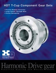
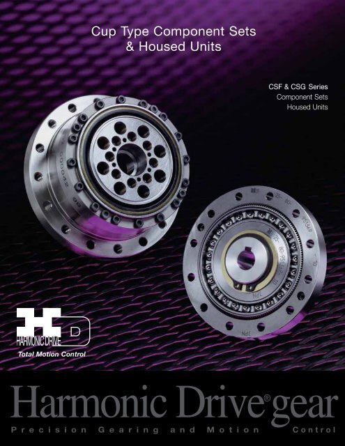
Cup Type Component Sets& Housed Units<strong>CSF</strong> & <strong>CSG</strong> SeriesComponent SetsHoused UnitsTotal Motion Control<strong>Harmonic</strong> <strong>Drive</strong>®gearP r e c i s i o n G e a r i n g a n d M o t i o n Control
ContentsABOUT <strong>Harmonic</strong> <strong>Drive</strong>Ordering Information 4Strain Wave Gearing 5System Components 5Driving Configurations 6Application Examples 7Rating Table 10Technical Terms, Strength & Life 13Selection Procedure 15Selection Example 16COMPONENT TYPE <strong>CSF</strong>, <strong>CSG</strong>-2AExternal Dimension & Shape 17External Dimension table 19Grease Lubrication 21Oil Lubrication 24Recommended Tolerances for Assembly 26Wave Generator Bore Modifications 27Assembly of the Flexspline, Installation 28Assembly of the Flexspline, Bolts and Screws 29Assembly of Circular Spline, Bolts 30Assembly Procedure 31UNIT TYPES <strong>CSF</strong>, <strong>CSG</strong>-2UHExternal Dimensions of Housed Unit 32Specifications for Cross Roller Bearing 33Output Bearing Life 35Recommended Tolerances for Assembly 36ENGINEERING DATAEfficiency of Component Set 38Efficiency of Housed Unit 41No Load Running Torque 44Starting Torque and Backdriving Torque 48Positioning Accuracy 49Torsional Stiffness 50Hysteresis Loss 51Backlash from Oldham Coupling 51Surface Treatment 51<strong>Harmonic</strong> <strong>Drive</strong> <strong>LLC</strong> 800-921-33323
Ordering InformationModelCustomized Specification (special)Size 2A - Component Set such as shape and performance2UH - Housed Unit SetModel NameIndicates short cup design<strong>Harmonic</strong> <strong>Drive</strong>® gearingGear RatioGR = Specificationfor Component<strong>CSF</strong>: Standard version<strong>CSG</strong>: High torque version<strong>Harmonic</strong> <strong>Drive</strong>® Gear Revolution<strong>Harmonic</strong> <strong>Drive</strong>® precision gear continues to evolve by improving performance and functionality.SSeriesBy pursuingstrength andstiffness, a new<strong>CSF</strong><strong>CSG</strong> SeriesThe <strong>CSG</strong> achieved a 30% increasein torque capacity. Life (L10) wasincreased from 7,000 hrs to 10,000 hrs.The <strong>CSF</strong> achievedtooth profilea reduction inwas invented.axial length ofThe “S” tooth Series approximately 50% Ratio 30:1 was added fordoubled thehigher output speeds.torque, lifeand stiffness.Ratio 30:1Miniature SeriesMiniature series was developed to expandthe range of <strong>Harmonic</strong> <strong>Drive</strong>® gearing.Tooth ProfilesThe <strong>Harmonic</strong> <strong>Drive</strong>® <strong>CSF</strong>/<strong>CSG</strong> component sets and housed unitspresented in this catalog incorporate the “S” gear tooth profile. Thispatented tooth profile provides a significant improvement in gear operatingcharacteristics and performance.The new “S” tooth profile significantly increases the region of toothengagement. For the traditional tooth profile 15% of the total numberof teeth are in contact, while for the new profile up to 30% of the teethare in contact. The increased number of teeth in engagement results ina 100% increase in torsional stiffness in the low & mid torque ranges.The new tooth profile also features an enlarged tooth root radius,which results in a higher allowable stress and a corresponding increasein torque capacity. Furthermore, the enlarged region of tooth engagementleads to a more even loading of the Wave Generator bearing,resulting in more than double the life expectancy for the gear.Initial EngagementFull Engagement4
Principle and StructureGEARHEADCOMPONENT SETCross Roller BearingOutput FlangeCircular Spline(case)Wave Generator(input)FlexsplineWave GeneratorCircular SplineFlexsplineSystem ComponentsThe Flexspline is a non-rigid, thin cylindrical cup with external teeth on a slightly smaller pitch diameter than the Circular Spline.It fits over and is held in an elliptical shape by the Wave Generator.The WAVE GENERATOR is a thin raced ball bearing fitted onto an elliptical plug serving as a high efficiency torque converter.The CIRCULAR SPLINE is a rigid ring with internal teeth, engaging the teeth of the Flexspline across the major axis of the Wave Generator.0 ºCircular Spline90º 360ºWave GeneratorFlexsplineThe Flexspline is elliptically shaped by TheWave Generator and engaged with theCircular Spline at the major elliptical axis.The teeth completely disengage on theminor axis.When the Circular Spline is fixed andthe Wave generator rotates clockwise,the Flexspline is elastically deformedand rotates counterclockwise relative tothe Circular Spline.For each 360 degrees clockwisemovement of the Wave Generator,theFlexspline moves counterclockwise bytwo teeth relative to the Circular Spline.<strong>Harmonic</strong> <strong>Drive</strong> <strong>LLC</strong> 800-921-3332 5
Driving ConfigurationsDriving ConfigurationsA variety of different driving configurationsare possible, as shown below.The reduction ratio given in the tables onpage 10 and 11 correspond to arrangement1, in which the Wave Generatoracts as the input element, the CircularSpine is fixed and the Flexspine acts asthe output element.1. Reduction Gearing2. Reduction GearingCS FixedFS FixedWG InputWG InputFS OutputCS OutputRatio = –R[Equation 1] Ratio = R + 111[Equation 2]Input and output in opposite direction.Input and output in same direction.3. Reduction GearingWG FixedFS InputCS OutputRatio =R + 1R[Equation 3]Input and output in same direction.4. Speed Increaser GearingWG FixedCS InputFS OutputRRatio = [Equation 4]R + 15. Speed Increaser GearingCS FixedFS InputWG OutputRatio = – 1 [Equation 5]RInput and output in opposite direction.1Ratio = [Equation 6]R + 17. Differential GearingWG Control InputCS Main <strong>Drive</strong>-InputFS Main <strong>Drive</strong>-OutputNumerous differential functions can beobtained by combinations of the speedand rotational direction of the three basicelements.6
Application ExampleThe <strong>CSF</strong> Cup-Style Component Set achieves higher performance thanthe Pancake Style Component Set in the same package size.<strong>CSF</strong> SeriesComponent SetPancake TypeComponent Set<strong>Harmonic</strong> <strong>Drive</strong> <strong>LLC</strong> 800-921-33327
Application ExampleTool ChangerMulti-joint Robot8
Application ExampleHoused Unit -Direct Connectionto Servo MotorHoused Unit -Input Shaft Option<strong>Harmonic</strong> <strong>Drive</strong> <strong>LLC</strong> 800-921-3332 9
<strong>CSF</strong> Rating TableTable 1Size Ratio Rated Limit for Limit for Limit for Maximum Limit for MomentTorque Repeated Average Momentary Input Average ofat Peak Torque Peak Speed Input Inertia2000 Torque Torque SpeedT rrpm Nm Nm Nm rpm rpmNm in-lb Nm in-lb Nm in-lb Nm in-lb Oil Grease Oil Grease x10 -4 kg•m 2 x10 -5 kgf•m•s 230 0.9 8 1.8 16 1.4- 12 3.3 298 50 1.8 16 3.3 29 2.3- 20 6.6 58 14000 8500 6500 3500 0.003 0.0031100 2.4 18 4.8 42 3.3- 29 9.0 8030 2.2 19 4.5 40 3.4- 30 8.5 7511 50 3.5 31 8.3 73 5.5- 49 17 150 14000 8500 6500 3500 0.012 0.012100 5.0 44 11 97 8.9- 79 25 22130 4.0 35 9.0 80 6.8 60 17 15014 50 5.4 48 18 159 6.9 61 35 310 14000 8500 6500 3500 0.033 0.03480 7.8 69 23 204 11 97 47 416100 7.8 69 28 248 11 97 54 47830 8.8 78 16 142 12 106 30 26650 16 142 34 301 26 230 70 62017 80 22 195 43 381 27 239 87 770 10000 7300 6500 3500 0.079 0.081100 24 212 54 478 39 345 108 956120 24 212 54 478 39 345 86 76130 15 133 27 239 20 177 50 44350 25 221 56 496 34 301 98 86720 80 34 301 74 655 47 411 127 1124 10000 6500 6500 3500 0.193 0.197100 40 354 82 726 49 434 147 1301120 40 354 87 770 49 434 147 1301160 40 354 92 814 49 434 147 130130 27 239 50 443 38 336 95 84150 39 345 98 868 55 487 186 164625 80 63 558 137 1212 87 770 255 2257 7500 5600 5600 3500 0.413 0.421100 67 593 157 1389 108 956 284 2513120 67 593 167 1478 108 956 304 2690160 67 593 176 1558 108 956 314 277930 54 478 100 885 75 664 200 177050 76 673 216 1912 108 956 382 338132 80 118 1044 304 2690 167 1478 568 5027 7000 4800 4600 3500 1.69 1.72100 137 1212 333 2947 216 1912 647 5726120 137 1212 353 3124 216 1912 686 6071160 137 1212 372 3292 216 1912 686 607150 137 1212 402 3558 196 1735 686 607180 206 1823 519 4593 284 2513 980 867340 100 265 2345 568 5027 372 3292 1080 9558 5600 4000 3600 3000 4.50 4.59120 294 2602 617 5460 451 3991 1180 10443160 294 2602 647 5726 451 3991 1180 1044350 176 1558 500 4425 265 2345 950 840880 313 2770 706 6248 390 3452 1270 1124045 100 353 3124 755 6682 500 4425 1570 13895 5000 3800 3300 3000 8.68 8.86120 402 3558 823 7284 620 5487 1760 15576160 402 3558 882 7806 630 5576 1910 1690450 245 2168 715 6328 350 3098 1430 1265680 372 3292 941 8328 519 4593 1860 1646150 100 470 4160 980 8673 666 5894 2060 18231 4500 3500 3000 2500 12.5 12.8120 529 4682 1080 9558 813 7195 2060 18231160 529 4682 1180 10443 843 7461 2450 2168350 353 3124 1020 9027 520 4602 1960 1734680 549 4859 1480 13098 770 6815 2450 2168358 100 696 6160 1590 14072 1060 9381 3180 28143 4000 3000 2700 2200 27.3 27.9120 745 6593 1720 15222 1190 10532 3330 29471160 745 6593 1840 16284 1210 10709 3430 3035610
Rating TableTable 2Size Ratio Rated Limit for Limit for Limit for Maximum Limit for MomentTorque Repeated Average Momentary Input Average ofat 2000 Peak Torque Peak Speed Input InertiaTr Torque Torque rpm SpeedrpmrpmNm in-lb Nm in-lb Nm in-lb Nm in-lb Oil Grease Oil Grease x10 -4 kg•m 2 x10 -5 kgf•m•s 250 490 4337 1420 12567 720 6372 2830 2504680 745 6593 2110 187 1040 9204 3720 3292265 100 951 8416 2300 20355 1520 13452 4750 42038 3500 2800 2400 1900 46.8 47.8120 951 8416 2510 22214 1570 13895 4750 42038160 951 8416 2630 23276 1570 13895 4750 4203850 872 7717 2440 21594 1260 11151 4870 4310080 1320 11682 3430 30356 1830 16196 6590 5832280 100 1700 15045 4220 37347 2360 20886 7910 70004 2900 2300 2200 1500 122 124120 1990 17612 4590 40622 3130 27701 7910 70004160 1990 17612 4910 43454 3130 27701 7910 7000450 1180 10443 3530 31241 1720 15222 6660 5894180 1550 13718 3990 35312 2510 22214 7250 6416390 100 2270 20090 5680 50268 3360 29736 9020 79827 2700 2000 2100 1300 214 218120 2570 22745 6160 54516 4300 38055 9800 86730160 2700 23895 6840 60534 4300 38055 11300 10000550 1580 13983 4450 39383 2280 20178 8900 7876580 2380 21063 6060 53631 3310 29294 11600 102660100 100 2940 26019 7350 65048 4630 40976 14100 124785 2500 1800 2000 1200 356 363120 3180 28143 7960 70446 5720 50622 15300 135405160 3550 31418 9180 81243 5720 50622 15500 137175<strong>CSG</strong> Rating TableTable 3Size Ratio Rated Limit for Limit for Limit for Maximum Limit for MomentTorque Repeated Average Momentary Input Average ofat 2000 Peak Torque Peak Speed Input InertiaTr Torque Torque rpm SpeedrpmrpmNm in-lb Nm in-lb Nm in-lb Nm in-lb Oil Grease Oil Grease x10 -4 kg•m 2 x10 -5 kgf•m•s 250 7.0 62 23 204 9 80 46 40714 80 10 89 30 266 14 124 61 540 14000 8500 6500 3500 0.033 0.0034100 10 89 36 319 14 124 70 62050 21 186 44 390 34 301 91 80517 80 29 257 56 496 35 310 113 1000 10000 7300 6500 3500 0.079 0.081100 31 274 70 620 51 451 143 1266120 31 274 70 620 51 451 112 99150 33 292 73 646 44 389 127 112480 44 389 96 850 61 540 165 146020 100 52 460 107 947 64 566 191 1690 10000 6500 6500 3500 0.193 0.197120 52 460 113 1000 64 566 191 1690160 52 460 120 1062 64 566 191 169050 51 451 127 1124 72 637 242 214280 82 726 178 1575 113 1000 332 293825 100 87 770 204 1805 140 1239 369 3266 7500 5600 5600 3500 0.413 0.421120 87 770 217 1920 140 1239 395 3496160 87 770 229 2027 140 1239 408 361150 99 876 281 2487 140 1239 497 439980 153 1354 395 3496 217 1920 738 653132 100 178 1575 433 3832 281 2487 841 7443 7000 4800 4600 3500 1.69 1.72120 178 1575 459 4062 281 2487 892 7894160 178 1575 484 4283 281 2487 892 789450 178 1575 523 4629 255 2257 892 789480 268 2372 675 5974 369 3266 1270 1124040 100 345 3053 738 6531 484 4283 1400 12390 5600 4000 3600 5000 4.50 4.59120 382 3381 802 7098 586 5186 1530 13541160 382 3381 841 7443 586 5186 1530 13541<strong>Harmonic</strong> <strong>Drive</strong> <strong>LLC</strong> 800-921-333211
<strong>CSG</strong> Rating TableTable 4Size Ratio Rated Limit for Limit for Limit for Maximum Limit for MomentTorque Repeated Average Momentary Input Average ofat 2000 Peak Torque Peak Speed Input InertiaTr Torque Torque rpm SpeedrpmrpmNm in-lb Nm in-lb Nm in-lb Nm in-lb Oil Grease Oil Grease x10 -4 kg•m 2 x10 -5 kgf•m•s 250 229 2,027 650 5,753 345 3,053 1,235 10,93080 407 3,602 918 8,124 507 4,487 1,651 14,61145 100 459 4,062 982 8,691 650 5,753 2,041 18,063 5,000 3,800 3,300 3,000 8.68 8.86120 523 4,629 1,070 9,470 806 7,133 2,288 20,249160 523 4,629 1,147 10,151 819 7,248 2,483 21,97580 484 4,283 1,223 10,824 675 5,974 2,418 21,39950100 611 5,407 1,274 11,275 866 7,664 2,678 23,700120 688 6,089 1,404 12,425 1,057 9,354 2,678 23,7004,500 3,500 3,000 2,500 12.5 12.8160 688 6,089 1,534 13,576 1,096 9,700 3,185 28,18780 714 6,319 1,924 17,027 1,001 8,859 3,185 28,18758100 905 8,009 2,067 18,293 1,378 12,195 4,134 36,586120 969 8,576 2,236 19,789 1,547 13,691 4,329 38,3124,000 3,000 2,700 2,200 27.3 27.9160 969 8,576 2,392 21,169 1,573 13,921 4,459 39,46280 969 8,576 2,743 24,276 1,352 11,965 4,836 42,79965100 1,236 10,939 2,990 26,462 1,976 17,488 6,175 54,649120 1,236 10,939 3,263 28,878 2,041 18,063 6,175 54,6493,500 2,800 2,400 1,900 46.8 47.8160 1,236 10,939 3,419 30,258 2,041 18,063 6,175 54,64912
Technical TermsDefinition of RatingsRated Torque (Tr)Rated torque indicates allowable continuous load torque at2000 rpm input speed.Limit for Repeated Peak Torque (refer to figure 1)During acceleration a deceleration the <strong>Harmonic</strong> <strong>Drive</strong>® gearexperiences a peak torque as a result of the moment ofinertia of the output load.Limit for Average TorqueIn cases where load torque and input speed vary, it is necessaryto calculate an average value of load torque. The table indicatesthe limit for average torque. The average torque calculatedmust not exceed this limit.Limit for Momentary Peak Torque (refer to figure 1)The gear may be subjected to momentary peak torques inthe event of a collision or emergency stop. The magnitude andfrequency of occurrence of such peak torques must be kept toa minimum and they should, under no circumstance, occur duringnormal operating cycle. The allowable number of occurrencesof the momentary peak torque may be calculated by usingequation 7 on page 13. Also see section “strength and life”.Figure 1Strength and LifeThe non-rigid Flexspline is subjected to repeated deflections, and itsstrength determines the torque capacity of the <strong>Harmonic</strong> <strong>Drive</strong>® gear.The values given for Rated Torque at Rated Speed and for the allowableRepeated Peak Torque are based on an infinite fatiguelife for the Flexspline.The torque that occurs during a collision must be below themomentary peak torque (impact torque). The maximum numberof occurrences is given by the equation below.[Equation 7]1.0 X 10 4 n: Input speed before collision (r/min)N = ____________2 X n X t t: Time interval during collision (sec)60Please note:If this number is exceeded, the Flexspline may experiencea fatigue failure.Ratcheting phenomenonWhen excessive torque is applied while the gear is in motion,the teeth between the Circular Spline and Flexspline may not engageproperly. This phenomenon is called ratcheting and the torque atwhich this occurs is called ratcheting torque. Ratcheting may causethe Flexspline to become non-concentric with the Circular Spline.(See figure 1 & 2 on page 13) Operating in this condition may resultin shortened life and a Flexspline fatigue failure.Figure 2Abnormal Impact TorqueLoad TorqueNumber of Rotationsof Wave GeneratorStartRoutineStopSpeed CycleStartTimeLoad TorqueRepeated Peak TorqueMomentary Peak TorqueTimeCircular SplineFlexsplineThis condition is called “dedoidal”.Maximum Input Speed, Limit for average input speedDo not exceed the allowable rating.Moment of InertiaThe rating indicates the moment of inertia reflected to thewave generator (gear input).Note!When ratcheting occurs, the teeth mesh abnormally as shown above.Vibration and Flexspline damage may occur.Once ratcheting occurs, the teeth wear excessively and theratcheting torque may be lowered.<strong>Harmonic</strong> <strong>Drive</strong> <strong>LLC</strong> 800-921-333213
Technical Terms<strong>CSF</strong> Ratcheting Torque Table 4 NmSizeRatio30 50 80 100 120 1608 11 12 - 14 - -11 29 34 - 43 - -14 59 88 110 84 - -17 100 150 200 160 120 -20 170 220 350 260 240 22025 340 450 680 500 470 45032 720 980 1400 1000 980 98040 - 1800 2800 2100 1900 180045 - 2700 3900 3100 2800 260050 - 3700 5400 4100 3800 360058 - 5800 8200 6400 5800 560065 - 7800 11000 9400 8300 800080 - 14000 22000 16000 15000 1400090 - 20000 30000 23000 21000 20000100 - 29000 44000 33000 30000 28000Table 5Nm<strong>CSF</strong> Buckling TorqueSizeAll Ratio8 3511 9014 19017 33020 56025 100032 220040 430045 580050 800058 1200065 1700080 3100090 45000100 58000<strong>CSG</strong> Ratcheting Torque Table 6 NmSizeRatio50 80 100 120 16014 110 140 100 - -17 190 260 200 150 -20 280 450 330 310 28025 580 880 650 610 58032 1200 1800 1300 1200 120040 2300 3600 2700 2400 2300Table 7Nm<strong>CSG</strong> Buckling TorqueSizeAll Ratio14 26017 50020 80025 170032 350040 6700The Life of a Wave GeneratorThe normal life of a gear is determined by the life of the wavegenerator bearing. The life may be calculated by using theinput speed and the output load torque.Rated Lifetime L n : (n = 10 or 50)L 10 <strong>CSF</strong> : 7,000 <strong>CSG</strong>: 10,000L 50 <strong>CSF</strong> : 35,000 <strong>CSG</strong> : 50,000Relative Torque RatingThe chart below shows the various torque specificationsrelative to rated torque. Rated Torque has been normalizedto 1 for comparison.Equation for the expected life of the wave generator undernormal operating conditions is given by the equation below.1716Figure 3Buckling Torque[Equation 8]Lh = Ln • ( Tr ) 3 • ( Nr )Tav NavLh : Expected Life, hoursLn : Rated Lifetime at L 10 or L 50Tr : Rated Torque (Tables 1, 2, 3)Nr : Rated input speed (2000 rpm)Tav : Average load torque on output side (page 15)Nav : Average input speed (page 15)Load Torque ( Rated Torque = 1 )109Racheting Torque87Life of the Wave Generator65Fatigue Strength of Flexspline4Momentary Peak Torque32 Repeated Peak Torque1Rated Torque0 10 5 10 6 10 7 10 8 10 9Total Number of Input Rotations10 101414
Selection ProcedureSize SelectionGenerally, the operating conditions consist of fluctuating torquesand output speeds. Also, an unexpected impact output torquemust be considered.The proper size can be determined by converting fluctuating load torqueinto average load torque and equivalent load torque. This procedureinvolves selecting the size based on load torque for componentsets.This procedure does not consider the life of the output bearing forhoused units. Determining the life of the output bearing for variousaxial, radial, and moment loads is outlined on page 34.Figure 4Flow Chart for selecting a sizePlease use the flowchart shown below for selecting a size.Operating conditions must not exceed the performanceratings as described on page 13.Calculation of the average output torqueTav = 3 n 1•t 1•|T1| 3 +n2•t 2•|T2| 3 + ... n n•t n•|Tn| 3n 1•t 1+n2•t 2+ ... n n t nMake a preliminary model delection with thefollowing conditions.+Torque_T 1T nT 2T 4T 3t 1 t 2 t 3 t 4 t nn 2n 1n 3n nTimeAverage Output SpeedNav = n 1t 1 + n2t 2 ... + nnt nt 1+t2 ... + tnDetermine Gear Ration i max < = Rn o maxn i max may be limited by the motor.Calculation of the average input speedn i av = n o av •RCalculation of maximum input speedn i max = n o max •Rrpmn 1 n 2 n n are an average value. TimeParametersLoad TorqueTn (Nm)Timetn (sec)Output Speednn (rpm)Normal Operating PatternAcceleration T1,t1, n 1Regular Operation T2,t2, n 2Deceleration T3,t3, n 3Dwell T4,t4, n 4Maximum RPMMax output speedn o maximumMax input speedn i maximumImpact Torquen 4Ts,ts, n sConsider a different Size or change operating requirementsNGNGNGNGNGn i av < = Limit for average speedn i max < = Limit for maximum speedOKConfirm if T 1 and T 3 are less than therepeated peak torque specification.OKConfirm if Ts (impact torque) is less thanthe momentary peak torque specification.OKCalculate the allowable number of rotationsduring impact torque.Ns = 104 ••••••Ns < = 1.0X10 42• n s•R •t s60OKCalculate wave generator life.L h= L n• ()3•( Tr nr Tav n i av)Make sure that the calculated life is suitablefor the application.RatingsRated TorqueRated SpeedTrnr =2000 rpmOKThe model number is determined.<strong>Harmonic</strong> <strong>Drive</strong> <strong>LLC</strong> 800-921-333215
Selection ExampleValues of an each Load Torque PatternLoad Torque Tn (Nm) no max = 14 rpmTime tn (sec) ni max = 1800 rpmOutput Speednn (rpm)Normal Operating PatternAcceleration T 1 = 400 Nm, t 1 = 0.3 sec, n 1 = 7 rpm T s = 500 Nm, t s = 0.15 sec, n s = 14 rpmRegular Operation Stop T 2 = 320 Nm, t 2 = 3 sec, n 2 = 14 rpmDeceleration T 3 = 200 Nm, t 3 = 0.4 sec, n 3 = 7 rpm L10 = 7000 hrs.Dwell T 4 = 0 Nm, t 4 = 0.2 sec, n 4 = 0 rpm Oil LubricationTav (Nm)3 7rpm•0.3sec•|400Nm| 3 +14rpm•3sec•|320Nm| 3 +7rpm•0.4sec•|200Nm| 3Tav =7rpm•0.3sec+14rpm•3sec+7rpm•0.4secTav =319Nm 12014 rpmn i av = 12 rpm •120 = 1440 rpmn o max ni max (rpm)n i max = 14 rpm •120 = 1680 rpmniav =1440rpm
External Dimension & ShapeW av e G e n e r at o r C o m p o n e n t s1. Ball Separator12 32. Wave Generator BearingH23. Wave Generator Plug4. InsertøU25. Rub Washer6. Snap Ring7. Wave Generator Hub4 5 6 7<strong>CSF</strong>-14,17,20,25,32,45,58,90<strong>CSF</strong>-40,50,65,80,100‐There is a difference in appearance of the the ball separator between <strong>CSF</strong> and <strong>CSG</strong>.(<strong>CSG</strong> size 14 and 17 use the same ball separator as <strong>CSF</strong>.<strong>CSF</strong> all sizes<strong>CSG</strong>-20 and above<strong>Harmonic</strong> <strong>Drive</strong> <strong>LLC</strong> 800-921-333217
External Dimension & Shape2–NFL–øMøZ12–NcDC1bABEC2FOc2–øPWøaQøI h6øaøJøK H6d3d2øU1øA h6XT1GøV H7YR–øSøZ2R0.3d1d1L–øMZ11.5 +0.10H 01-0.1e 2-fQ3 P7 -0.006-0.016(Flexspline Interface #8)Detailed drawings are also available. No key on WG hub for #8, 11, 14, 17.Flexspline Dowel Pin HoleDowel Pin OptionIn cases where the gear will see loads near theMomentary Peak Torque level, the use of additionaldowel pins in addition to the screws is recommended.Dowel pin holes are manufactured by reamer andthe dimensions are shown. In addition, the <strong>CSF</strong> hasa different number of dowel pin holes than the <strong>CSG</strong>.T 22– NF2– øccøZ318
External DimensionsTable 88 11 14 17 20 25 32 40øA h6 30 40 50 60 70 85 110 135B <strong>CSF</strong> 22.1-0.3 025.8 -0.7 028.5 -0.8 032.5 -0.9 033.5 -1.0 037 -1.0 044 -1.1 053 -1.10<strong>CSG</strong> - - 28.5-0.4 032.5 -0.4 033.5 -0.4 037 -0.5 044 -0.6 053 -0.60GC 112.5 +0.2014.5 +0.4017.5 +0.4020 +0.5021.5 +0.6024 +0.6028 +0.60 34+0.6 0C 29.6 11.3 11 12.5 12 13 16 19D 2.7 2 2.4 3 3 3 3.2 4E - 2 2 2.5 3 3 3 4F 4.5 5 6 6.5 7.5 10 14 17<strong>CSF</strong> - - 0.4 0.3 0.1 2.1 2.5 3.3<strong>CSG</strong> - - 1.4 1.6 1.5 3.5 4.2 5.6<strong>CSF</strong> 12 16 17.6 19.5 20.1 20.2 22 27.5H 01-0.1<strong>CSG</strong> - - 18.5 20.7 21.5 21.6 23.6 29.7øI h6LøVH 2- - - - - - - 0.4Ratio=30 - 31 38 48 54 67 90 110Ratio=30 - 31 38 48 55 68 90 -øJ 12.3 17.8 23 27.2 32 40 52 64øK H6 6 6 11 10 16 20 26 32<strong>CSF</strong> 8 8 6 12 12 12 12 12<strong>CSG</strong> - - 8 16 16 16 16 16øM 2.2 2.9 3.5 3.4 3.5 4.5 5.5 6.6N CM2 M2.5 M3 M3 M3 M4 M5 M6N F- - M3 M3 M3 M4 M5 M6O 3 3 6 6.5 4 6 7 9øP 2.2 2.9 - - 3.5 4.5 5.5 6.6Q(PCD) 25.5 35 44 54 62 75 100 120R - 6 6 6 8 8 8 8øS - 3.4 4.5 5.5 5.5 6.6 9 11T 1(PCD) - 12 17 19 24 30 40 50T 2(PCD) - 15.2 18.5 21.5 27 34 45 56øU 17 11 14 18 21 26 26 32øU 2- - - - - - - 32(H7)standard 3 5 6 8 9 11 14 14maximum - - 8 10 13 15 15 20WJs9 - - - - 3 4 5 5X - - - - 10.4 +0.10 12.8+0.1 0 16.3+0.1 0 16.3+0.1 0Y - C0.2 C0.3 C0.4 C0.4 C0.4 C0.4 C0.4øZ 10.1 0.2 0.25 0.20 0.25 0.25 0.25 0.3øZ 2- 0.2 0.25 0.25 0.25 0.3 0.5 0.5øZ 3- 0.02 0.02 0.02 0.02 0.02 0.02 0.02øa21.5 30 38 45 53 66 86 106Minimumb housing clearance 11.34 14 17.1 19 20.5 23 26.8 33c - - 1 1 1.5 1.5 1.5 2ø cc H7<strong>CSF</strong> - 2 3 3 3 4 5 6<strong>CSG</strong> - - 2.5 3 3 4 5 5d 1C0.3 C0.4 C0.4 C0.4 C0.4 C0.4 C0.4 C0.4d 2C0.3 C0.4 C0.4 C0.4 C0.4 C0.4 C0.4 C0.4d 3C0.3 C0.3 C0.5 C0.5 C0.5 C0.5 C0.5 C0.5e 2 3 2.5 3 - - - -f M2X3 M3X4 M3X4 M3X6 - - - -Weight (kg) 0.026 0.05 0.09 0.15 0.28 0.42 0.89 1.7(mm)<strong>Harmonic</strong> <strong>Drive</strong> <strong>LLC</strong> 800-921-333219
External DimensionsGH1 0-0.1øI h6LøVTable 945 50 58 65 80 90 100øA h6 155 170 195 215 265 300 330B 58.5-1.2 064 -1.3 075.5 -1.3 083 -1.3 0101 -1.3 0112.5 -1.4 0125 -1.60C 1 38 +0.60 41+0.6 0 48+0.6 0 52.5+0.6 0 64+0.6 0 71.5+0.8 0 79+1.0 0C 2 20.5 23 27.5 30.5 37 41 46D 4.5 5 5.8 6.5 8 9 10E 4 4 5 5 6 6 6F 19 22 25 29 36 41 46<strong>CSF</strong> 3.7 4.2 4.8 5.8 6.6 7.5 8.3<strong>CSG</strong> 6.3 7 8.2 9.5 — — —<strong>CSF</strong> 27.9 32 34.9 40.9 49.1 48.2 56.7<strong>CSG</strong> 30.5 34.8 38.3 44.6 — — —H 2 — 0.8 — 2.2 3.1 — 4.51/30 except 124 135 156 177 218 245 2721/30 — — — — — — —øJ 72 80 92.8 104 128 144 160øK H6 36 40 46 52 65 72 80<strong>CSF</strong> 12 12 12 12 16 16 16<strong>CSG</strong> 16 16 16 16 — — —øM 9 9 11 11 11 14 14N CM8 M8 M10 M10 M10 M12 M12N FM6 M8 M8 M8 M8 M12 M10O 12 13 15 15 15 18 20øP 9 9 11 11 11 14 14Q(PCD) 140 150 175 195 240 270 300R 8 8 8 8 10 8 12øS 13.5 15.5 15.5 18 18 22 22T 1(PCD) 54 60 70 80 100 110 130T 2(PCD) 61 68 79 90 114 120 142øU 132 32 40 48 55 60 65øU 2— 32 — 48 55 — 65(H7)Standard 19 19 22 24 28 28 28Maximum 20 20 25 30 35 37 40WJs9 6 6 6 8 8 8 8X 21.8 +0.10 21.8+0.1 0 24.8+0.1 0 27.3+0.2 0 31.3+0.2 0 31.3+0.2 0 31.3+0.2 0Y C0.4 C0.8 C0.8 C0.8 C0.8 C0.8 C0.8øZ 10.5 0.5 0.5 0.5 0.5 1.0 1.0øZ 20.75 0.75 0.75 1.0 1.0 1.0 1.0øZ 30.02 0.02 0.02 0.02 0.02 0.02 0.02øa119 133 154 172 212 239 265bMinimumhousing clearance 36.5 39 46.2 50 61 68.5 76c 2 2 2.5 2.5 3 3 3øcc H7 6 8 8 8 8 12 10d 1C0.4 C0.4 C0.4 C0.4 C0.4 C0.4 C0.4d 2C0.4 C0.4 C0.4 C0.4 C0.4 C0.4 C0.4d 3C0.5 C0.5 C0.5 C0.5 C0.5 C0.5 C0.5e — — — — — — —f — — — — — — —Weight (kg) 2.3 3.2 4.7 6.7 12.4 17.6 23.5(mm)The pilot diameter for the Circular spline can be either ØI or ØA. Surface A is the recommended mounting surface.The following parameters can be modified to accommodate customer-specific requirements.Wave Generator: ØV, X, WFlexspline: R, ØSCircular Spline: ØM, L20
LubricationGrease lubricant is the standard for the <strong>CSF</strong> and <strong>CSG</strong> units. The temperature range is shown below.LubricantTypeLubricant Type TemperatureGrease <strong>Harmonic</strong> Grease SK-1AGrease <strong>Harmonic</strong> Grease SK-2Grease <strong>Harmonic</strong> Grease 4B-No.2Oil Industrial gear oil #2(high pressure) ISO VG68Grease SK-1A 0ºC~+40ºCGrease SK-2 0ºC~+40ºCGrease 4B-No.2 -10ºC~+70ºCOil ISO VG68 0ºC~+40ºC<strong>Harmonic</strong> Grease SK-1A - This grease is developed for a <strong>Harmonic</strong> <strong>Drive</strong>® gear and features good durability and efficiency.<strong>Harmonic</strong> Grease SK-2 - This grease is developed for a small size <strong>Harmonic</strong> <strong>Drive</strong>® gear and features smooth rotation of the Wave Generatorsince high pressure additive is liquefied.<strong>Harmonic</strong> Grease 4BNo.2 - This grease is developed for <strong>Harmonic</strong> <strong>Drive</strong>® gears and features long life and a wide range of temperature.Note 1 - Grease lubrication must have proper sealing, this is essential for 4B No.2.Rotating part: Oil seal with spring is needed.Mating part: O ring or seal adhesive is needed.Note 2 - The grease has the highest deterioration rate in the region where the grease is subjected to the greatest shear (near wave generator).Its viscosity is between JIS No.0 and No.00 depending on the operation.Ratio1/30Size 14 17 20 25 32SK-1A — — O O OSK-2 O O — — —4BNo.2 ∆ ∆ • • ••: recommended grease for long life and high load O: Standard ∆: SemistandardRatio 1/50 and aboveSize 14 17 20 25 32 40 45 50 58 65SK-1A — — O O O O O O O OSK-2 O O ∆ ∆ ∆ ∆ — — — —4BNo.2 • • • • • • • • • ••: recommended grease for long life and high load O: Standard ∆: SemistandardCharacteristics of GreaseGrease SK-1A SK-2 4BNo.2Durability O O •Fretting Resistance O O •Low Temp ∆ ∆ •Grease Leakage • • ∆•: Excellent O: Good ∆: Exercise CautionRecommended GreaseGrease SK-1A SK-2 4B No.2Base OilThickening AgentRefined mineral hydrocarbon Refined mineral hydrocarbon Hydrocarbon type syntheticbase oil base oil oil and polymerLithium soapthickenerLithium soapthickenerAdditive Organic molybdenum, etc. Organic molybdenum, etc. Organic molybdenum, etc.sNLGI Consistency No. No.2 No.2 No.1.5Viscosity (25C) cSt 265 to 295 265 to 295 290 to 320Melting Point 197ºC 198ºC 247ºCColor Yellow Green Light YellowLife5 Years in Airtight ContainerUrea21
LubricationGreasebProper lubrication of the gear is essential forhigh performance and reliability.cRecommend grease:SK-2 for sizes 8 thru 17Counter borefor bolt head.SK-1A for size 20 thru 65Note: <strong>Harmonic</strong> <strong>Drive</strong>® component sets areshipped with a rust-preventative oil. This oil is notsufficient for lubricating the gear, however, theappropriate grease may be applied directly ontop of this rust-preventative oil.ø dø aRecommended Size for Inner Case Table 10mmSize 8 11 14 17 20 25 32 40 45 50 58 65 80 90 100øA 21.5 30 38 45 53 66 86 106 119 133 154 172 212 239 265b 11.34 14 17.1 19 20.5 23 26.8 33 36.5 39 46.2 50 61 68.5 76c 0.5 0.5 1 1 1.5 1.5 1.5 2 2 2 2.5 2.5 3 3 3ød 13 16 16 26 30 37 37 45 45 45 56 62 67 73 79Grease Usage Table 11gramsSize 8 11 14 17 20 25 32 40 45 50 58 65 80 90 100Horizontal 1.2 2.9 5.5 10 16 30 60 110 170 220 360 460 850 1150 1500Output Up 1.4 3.5 7 12 18 35 70 125 190 240 380 500 900 1300 1700Output Down 1.8 4.4 8.5 14 21 40 80 145 220 275 460 600 1000 1500 1900CIRCULAR SPLINE FLEXSPLINE WAVE GENERATORApply thin coatto avoid rustFill the toothbedwith greaseFill cavity betweenretainer and insertwith greasewhen using inhigh speedApply thin coating ofgrease before installationPack bearing withgrease while slowlyrotating bearingFill thetoothbedwith greaseApply grease toinner surface inaccordance with avalue shown above.Apply grease toOldham couplingHORIZONTAL OUTPUT UP OUTPUT DOWNApply greaseto inner surfacein accordancewith a valueshown above.This mustbe 2X C.Apply greaseto inner surfacein accordancewith quantityshown in table.cFill 50%of this spacewith greasecApply greaseto inner surfacein accordancewith a quantityshown in table.22
LubricationGrease ChangeThe wear characteristics of the gear are strongly influenced by thecondition of the grease lubrication. The condition of the grease isaffected by the ambient temperature. The graph shows the maximumnumber of input rotations for various temperatures. This graph appliesto applications where the average load torque does not exceed therated torque.Note: Recommended Grease: SK-1A or SK-2In cases where the rated torque is exceeded, calculate the greasechange interval using the equation shown below.Equation where average load torque exceeds rated torque[Equation 9]L GT = L GTn X ( Tr ) 3TavSymbol of EquationGrease change (over rated torque), input rotationsL GTL GTnT rT avGrease change (below rated torque), input rotations (From Graph)Rated TorqueAverage load torque on outputNumber of Rotations10 10Grease Change Interval for Tav < Tr LGTnGrease Life4B No.210 9SK-1ASK-210 8Wave Generator Life10 720 40 60 80 100 120Grease Temperature (Cº)23
LubricationOil LubricantKind of LubricantName of Lubricant Table 12Industrial Mobil Exxon Showa Shell Cosmo Japan Energy Shin Nippon Oil Idemitsu Kosan General oil NOK KluberIndustrial Gear Mobil Spartan Omara Cosmo ES Bon nock Dafuni General Oil Shin tessoOil#2 ISO VG68 gear 626 EP68 oil 68 gear SE68 gear G68 M68 Supergear LW68 SP gear Roll 68 DE-68 EP(extreme pressure)Oil Level of Horizontal Usage Table 13mmSize 8 11 14 17 20 25 32 40 45 50 58 65 80 90 100A 6 8 10 12 14 17 24 31 35 38 44 50 59 66 74Horizontal Installation:Oil level should be maintained at the level “A” as shown.Oil Level for Horizontal UsageAOil LevelOil Level of Vertical Usage Table 14mmSize 8 11 14 17 20 25 32 40 45 50 58 65 80 90 100B 2 2.3 2.5 3 3 5 7 9 10 12 13 15 19 22 25Vertical Installation:If the input shaft is on top, lube holes are provided on the boss of theFlexspline to facilitate the flow of oil inside the Flexspline cup. The lubeholes serve as breathers if the component set is used with input down.When the <strong>Harmonic</strong> <strong>Drive</strong>® gear is to be used vertically with the WaveGenerator placed at the bottom, special consideration must be given.If the Wave Generator assembly is completely submerged in oil, the heatgeneration caused by churning oil will be substantial and a loss of efficiencywill result. It is recommended that the oil level be maintained in sucha way that approximately one half of the Wave Generator Bearing is submerged.Oil level should be maintained at the level “B” shown.To ensure a sufficient amount of lubricant it may be necessary to extendthe bottom area of the housing or to provide an external oil reservoir.A forced lubrication system may also be considered.BOil LevelBOil LevelOutput on TopOil Level of Vertical UsageOutput on Bottom24
LubricationDimension of Lube Hole of Flexspline Table 15mmSize 20 25 32 40 45 50 58 65 80 90 100T2 27 34 45 56 61 68 79 90 114 120 142B 2.5 2.5 3.5 3.5 3.5 5.5 5.5 5.5 6.5 6.5 6.5W 2.8 3.5 4.0 4.0 4.0 6.0 6.0 6.0 7.0 7.0 7.0t 1.2 1.2 1.4 1.4 1.4 2 2 2 3 3 3Size 8, 11, 14, 17 do not have any lube holesDimension of lube hole in FlexsplinetThreaded for DisassemblyDowel Pin HoleT22– ø BWOil Quantity Table 16litersSize 8 11 14 17 20 25 32 40 45 50 58 65 80 90 100B Amount of Oil 0.004 0.006 0.01 0.02 0.03 0.07 0.13 0.25 0.32 0.4 0.7 1.0 2.0 2.8 3.8Oil TemperatureIn normal use, the oil temperature must not exceed 90ºC,Above this temperature oil quickly loses its lubricating capabilities.Oil ChangeThe first oil change should be performed after 100 hours of operation.The need to perform subsequent oil changes will depend on operatingconditions, but should take place at intervals of approximately1000 running hours.Other notes: Avoid mixing different kinds of oil. The gear should be inan individual case when installed.High Temperature Lubricants<strong>Harmonic</strong> Grease 4B No.2Type of lubricant Standard temperature range Possible temperature rangegrease –10°C~+110°C –50ºC~+130ºCHigh Temperature LubricantType of lubricant Name of lubricant and manufacturer Possible temperature rangegrease Multemp SH-K2 Kyodo Yushi –30ºC~+50ºCMultemp AC-N Kyodo Yushi–55ºC~+60ºCHigh Temperature LubricantType of lubricant Name of lubricant and manufacturer Possible temperature rangeMobil grease 28 Mobil Grease 28 –5ºC~+160ºCoil Mobil SHC-626 –5ºC~+140ºCStandard temperature is the grease temperature during operation.It is not the ambient temperature.Iso Flex LDS-18 special A NOK kluber –25ºC~+80ºCoil SH-200-100CS Tore Silicon –10ºC~+110ºCShintesso D-32EP NOK kluber–25ºC~+90ºCThe temperature range of the grease can be extended as indicated inthe possible temperature range shown. At the low end of this rangethe efficiency will be low due to an increase in viscosity of the lubricant.At the high end of this range the lubricant life will be low due toan increased deterioration rate from the high temperature.25
Recommended Tolerances for AssemblyFor peak performance of the <strong>CSF</strong> Component Set it is essential that the following tolerances be observed when assembly is complete.Recommended tolerances for assemblyAttached Surfaced ACircular Spline Interfacea AARecommended Housing Tolerance H7BAttached Surfacee BWave Generator Interfacef BøcRecommended Shaft Tolerance h6AøgRecommended Shaft Tolerance h6BbAFlexspline InterfaceTolerances for Assembly Table 17Size 8 11 14 17 20 25 32 40 45 50 58 65 80 90 100a 0.008 0.011 0.011 0.012 0.013 0.014 0.016 0.016 0.017 0.018 0.020 0.023 0.027 0.029 0.031b 0.006 0.006 0.008 0.011 0.014 0.018 0.022 0.025 0.028 0.030 0.032 0.035 0.040 0.043 0.045øc 0.005 0.008 0.015 0.018 0.019 0.022 0.022 0.024 0.027 0.030 0.032 0.035 0.043 0.046 0.049d 0.010 0.010 0.011 0.015 0.017 0.024 0.026 0.026 0.027 0.028 0.031 0.034 0.043 0.050 0.057e 0.010 0.010 0.011 0.015 0.017 0.024 0.026 0.026 0.027 0.028 0.031 0.034 0.043 0.050 0.057f 0.012 0.012 0.017 0.020 0.020 0.024 0.024 0.032 0.032 0.032 0.032 0.032 0.036 0.036 0.036(0.008) (0.010) (0.010) (0.012) (0.012) (0.012) (0.013) (0.015) (0.015) (0.015) (0.015) (0.015) (0.015)øg 0.015 0.015 0.030 0.034 0.044 0.047 0.050 0.063 0.065 0.066 0.068 0.070 0.090 0.091 0.092(0.016) (0.018) (0.019) (0.022) (0.022) (0.024) (0.027) (0.030) (0.033) (0.035) (0.043) (0.046) (0.049)The values in parentheses indicate that Wave Generator does not have an Oldham coupling.Sealing structureA seal structure is needed to maintain the high durability of the gear and prevent grease leakage.Key Points to Verify• Rotating parts should have an oil seal (with spring), surface should be smooth (no scratches)• Mating flanges should have an O Ring, seal adhesive• Screws should have a thread lock(Loctite 242 recommended) or seal adhesive.(note)If you use <strong>Harmonic</strong> grease 4BNo.2, strict sealing is required.26
DiametersTable 18Hole Diameter of Wave Generator HubUnit: mmSize 8 11 14 17 20 25 32 40 45 50 58 65 80 90 100Standard Dimension 3 5 6 8 9 11 14 14 19 19 22 24 28 28 28Minimum Hole Dimension - - 3 4 5 6 6 10 10 10 13 16 16 19 22Maximum Hole Dimension - - 8 10 13 15 15 20 20 20 25 30 35 37 40Hole Diameter of Wave GeneratorHøV'Installation of Three Basic ElementsInstallation for Wave Generator and the maximum hole dimensions.Shown above is the standard hole dimension of the Wave Generator foreach size. The dimension can be changed within a range up to the maximumhole dimension shown in table 18. We recommend the dimension ofkeyway based on JIS standard. It is necessary that the dimension ofkeyways should sustain the transmission torque.Please note: Tapered holes are also available.In cases where a larger hole is required, use the Wave Generator without theOldham coupling. The maximum diameter of the hole should be consideredto prevent deformation of the Wave Generator plug by load torque.The dimension is shown in table 19 include the dimension ofdepth of keyway.Table 19Maximum Diameter or Hole without Oldham CouplingUnit: mmSize 8 11 14 17 20 25 32 40 45 50 58 65 80 90 100Maximum Diameter øV’ 10 14 17 20 23 28 36 42 47 52 60 67 72 84 95Min. thickness of plug H 5.7 6.7 7.2 7.6 11.3 11.3 13.7 15.9 17.8 19 21.4 23.5 28.5 31.3 34.9Direction for Thrust Force of Wave GeneratorAxial Force of Wave GeneratorFdirection for thrustforce in accelerationFdirection for thrustforce in decelerationWhen a <strong>CSF</strong>/<strong>CSG</strong> gear is used to accelerate a load, the deflection of theFlexspline leads to an axial force acting on the Wave Generator. This axialforce, which acts in the direction of the closed end of the Flexspline, mustbe supported by the bearings of the input shaft (motor shaft).When a <strong>CSF</strong>/<strong>CSG</strong> gear is used to decelerate a load, an axial force actsto push the Wave Generator out of the Flexspline cup. Maximum axial forceof the Wave Generator can be calculated by the equation shown below.The axial force may vary depending on its operating condition. The valueof axial force tends to be a larger number when using high torque, extremelow speed and constant operation. The force is calculated (approximately)by the equation. In all cases, the Wave Generator must be axially (in bothdirections), as well as torsionally, fixed to the input shaft.Equation for axial forceGear Ratioequationi=1/30 F=2x T x 0.07 x tan 32ºDi=1/50 F=2x T x 0.07 x tan 30ºDi=1/80 and up F=2x T x 0.07 x tan 20ºDSymbols for equationF axial force ND Gear Size x 0.00254 mT output torque Nm(note) Please contact us when you fix the Wave Generator hub and inputshaft using bolts.Calculation Examplesize : 32Ratio : i=1/50Output Torque : 300NmF=2x 300 x 0.07xtan 30º(32x0.00254)F=298N27
Assembly of the FlexsplineShape and dimension of Wave GeneratorThere is a difference between <strong>CSF</strong> series and <strong>CSG</strong> series withregard to the shape and dimension of the Wave Generator.Table 20 and Figure 5 show the comparison of the shape and dimensionfor the Wave Generator.During design and installation, please ensure there isno interference between the bolt of the Wave Generatorand Flexspline.Figure 5. Comparison of shape for Wave GeneratorH 1tG<strong>CSF</strong> SeriesComparison of Dimension of Wave Generator Table 20Size 14 17 20 25 32 40G<strong>CSF</strong> 0.4 0.3 0.1 2.1 2.5 3.3<strong>CSG</strong> 1.4 1.6 1.5 3.5 4.2 5.6H1 – 0 <strong>CSF</strong> 17.6 19.5 20.1 20.2 22 27.50.1<strong>CSG</strong> 18.5 20.7 21.5 21.6 23.6 29.7t <strong>CSF</strong> 2.5 2.5 2.9 2.8 3.8 4.5<strong>CSG</strong> 1.6 1.3 1.5 1.4 2.2 2.3G indicates Wave Generator depth inside the Flexspline measured fromthe open end of the Flexspline cup.t indicates the clearance between hub andFlexspline bolts.Installation of Flexspline1. Size #8A) For installation of the Flexspline on theoutput shaft use the plug shown on the right.B) The positioning of the output shaft andthe Flexspline should be determinedusing the plug.C) We recommend using an M3 socket headcap screw for connecting the plug to theoutput shaft. We also recommend usingLoctite 242.D) The open end of the Flexspline must belocated axially on the same plane as thetop surface of the circular spline.2. Recommended dimensions for FlexsplineClamp Rings required for sizes 11 and larger.M3 tapOutputShaft3 –0.005–0.015// 0.010÷ 0.010 Aø12 and upø6H6C0.2C0.2AC0.3Material : S45C1.4 0–0.1Hardness : HB201~269tH 1Plug0.1MAX.ø12.3 02.5GSocket HeadCapScrewPlug<strong>CSG</strong> SeriesFigure 6. Installation for Flexspline of Size 8R0.2 and upø3.5ø6g6Output ShaftFlexspline Clamp Ring Dimensions Table 21Size 11 14 17 20 25 32 40 45 50 58 65 80 90 100øD-0.1 017.8 24.5 29 34 42 55 68 74 83 95.8 106 130 145 162R +0.100.5 1.2 1.2 1.4 1.5 2 2.5 2 2.5 2.5 2.5 2.5 2.5 2.5t 2 2 2.5 2.5 5 7 7 8 8 12 12 15 20 25 0For installation, the flange diameter should not exceed the bossdiameter of Flexspline shown on figure 7. The flange which contactsthe diaphragm should have radius, R. A large diameter and flangewithout a radius may cause damage to the diaphragm.Recommended Dimensions of Flexspline Clamp RingDiaphragmAvoidFigure 73. Material and hardness for flange installation.D• Material : S45C (DIN C45)• Hardness : HB200~270RNote: For proper lubrication, please refer to lubrication requirements,p. 21.tHead of bolt, nut and washer shouldnot exceed the diameter of D.28
Assembly of the FlexsplineInstallation of the FlexsplineThe load is normally attached to the Flexspline using a bolt or screw.For high load torques dowel pins can be used in addition to boltsor screws.The strength of the selected bolt, clamp torque, surface condition ofbolt and thread, and coefficient of friction on the contact surface areimportant factors to consider.To determine transmission torque of the fastened part consider conditionsindicated above.Please fasten bolts with the proper torque for each size as indicated.Please use the table shown below to decide if dowel pins are needed.1. If the load torque is less than momentary peak torque shownon tables 1, 2, 3, then only bolts are needed.2. If the load torque is expected to reach momentary peak torque,both bolts and pins should be used.Use values on the list as a reference.Tables 22, 23 pertain to the <strong>CSF</strong> series.Tables 24, 25 pertain to the <strong>CSG</strong> series.<strong>CSF</strong> Series Flexspline Bolts Table 22Size 11 14 17 20 25 32 40 45 50 58 65 80 90 100Number 6 6 6 8 8 8 8 8 8 8 8 10 8 12Size M3 M4 M5 M5 M6 M8 M10 M12 M14 M14 M16 M16 M20 M20Pitch circle mm 12 17 19 24 30 40 50 54 60 70 80 100 110 130Clamp Torque Nm 2.0 4.5 9.0 9.0 15.3 37 74 128 205 205 319 319 622 622Torque Transmission 15 35 64 108 186 460 910 1440 2160 2550 3980 6220 8560 15170Capacity(bolt only)Nm<strong>CSF</strong> Series Flexspline Screws and Optional Dowel Pins Table 23Size 11 14 17 20 25 32 40 45 50 58 65 80 90 100Number 2 2 2 2 2 2 2 2 2 2 2 2 2 2Diameter mm 2 3 3 3 4 5 6 6 8 8 8 8 12 10Pitch circle mm 15.2 18.5 21.5 27 34 45 56 61 68 79 90 114 120 142Torque Transmission 29 74 108 167 314 725 1370 1950 3160 3710 5310 7910 12540 18450Capacity(bolt&pin) Nm1. The material of the thread must withstand the clamp torque.2. Recommended bolt : JIS B 1176 socket head cap screw strength range : JIS B 1051 over 12.93. Torque coefficient : K=0.24. Clamp coefficient A=1.45. Friction coefficient on the surface contacted: 0.156. Dowel Pin: parallel pin Material: S45C-Q Shear stress: 30 kgf/mm 2Standard BoltHoles (6)Standard BoltHoles (8)Standard BoltHoles (10)Standard BoltHoles (12)Dowel PinHoles (2)(option)Threads forDisassemblyDowel PinHoles (2)(option)Threads forDisassemblyDowelPin Holes(2)(option)Threads forDisassemblyDowel PinHoles (2)(option)Threads forDisassembly<strong>CSF</strong>-11,14,17 <strong>CSF</strong>-20~65,90 <strong>CSF</strong>-80 <strong>CSF</strong>-100<strong>CSG</strong> Series - Flexspline Bolts Table 24Size 14 17 20 25 32 40Number 6 6 8 8 8 8Size M4 M5 M5 M6 M8 M10Pitch Circle mm 17 19 24 30 40 50Clamp torque Nm 5.4 10.8 10.8 18.4 44.4 88.8Torque transmission Nm 43 77 130 230 555 1110capacity (bolt only)29
Assembly of Circular Spline<strong>CSG</strong> Series - Screws, Bolts and Optional Dowel Pins Table 25Size 14 17 20 25 32 40Dowel pin number 4 4 4 4 4 4Dowel pin diameter 3 3 3 4 5 6Pitch circle dia mm 18.5 21.5 27 34 45 56Torque transmission 120 166 242 481 1070 2040capacity(bolt&pin) Nm1. The material of the thread must withstand the clamp torque.2. Recommended bolt : JIS B 1176 socket head cap screw strength range : JIS B 1051 over 12.93. Torque coefficient : K=0.24. Clamp coefficient A=1.45. Friction coefficient on the surface contacted: 0.156. Dowel Pin: parallel pin Material:S45C-Q Shear stress: 30 kgf/mm 2Standard Bolts (6) Standard Bolts (8)4 Pins Threads for(option) Disassembly 4 Pins Threads for(option)Disassembly<strong>CSG</strong>-14,17<strong>CSG</strong>-20~40Installation of Circular Spline<strong>CSF</strong> Bolt Installation Table 26Size 8 11 14 17 20 25 32 40 45 50 58 65 80 90 100Number 8 8 6 12 12 12 12 12 12 12 12 12 16 16 16Size M2 M2.5 M3 M3 M3 M4 M5 M6 M8 M10 M10 M10 M10 M12 M12Pitch circle mm 25.5 35 44 54 62 75 100 120 140 150 175 195 240 270 300Clamp Torque Nm 0.17 0.35 2.0 2.0 2.0 4.5 9.0 15.3 37 37 74 74 74 7128 128Torque transmission 5 12 54 131 147 314 676 1150 2440 2620 4820 5370 8820 14450 16050capacity Nm<strong>CSG</strong> Bolt Installation Table 27Size 14 17 20 25 32 40Number 8 16 16 16 16 16Size M3 M3 M3 M4 M5 M6Pitch circle mm 44 54 62 75 100 120Clamp torque Nm 2.0 2.0 2.0 4.5 9.0 15.3Torque transmission 72 175 196 419 901 1530capacity Nm1. The material of the thread must withstand the clamp torque.2. Recommended bolt : JIS B 1176 socket head cap screw strength range : JIS B 1051 over 12.93. Torque coefficient : K=0.24. Clamp coefficient A=1.45. Friction coefficient on the surface contacted: 0.156. The open end of the Flexspline must be located axially on the same plane as the top surface of the circular spline.30
Assembly Procedure7. Ensure that the surface used for installation is flat and not skewed.8. Ensure that the installation surface does not have any burrs orforeign substances resulting from screw threading operations.9. Ensure sufficient clearance to prevent interference between theFlexspline and installed parts.10. When a bolt is inserted into a bolt hole during installation,make sure that the bolt fits securely and is not in an improperposition or inclination.11. Do not apply torque at recommended torque all at once. First,apply torque at about half of the recommended value to all bolts,then tighten at recommended torque. Order of tightening boltsmust be diagonal.12. Ensure that the Flexspline and Circular spline are concentricafter assembly.13. Do not damage Flexspline diaphragm or gear teeth during assembly.Note: For proper lubrication, please refer to lubrication requirements, p. 21-24.Assembly Order for Basic Three ElementsThe recommended sequences of assembly are illustrated below.Only after the Circular Spline and Flexspline are assembled in equipment is the Wave Generator assembled.If assembly is performed using a different method, Dedoidal assembly or teeth breakage may occur.It is essential that teeth of the Flexspline and Circular Spline mesh symmetrically for proper function.An eccentric tooth mesh (Dedoidal), will result in noise and vibration and may lead to early failure of the gear.When flexspline andwave generator areassembled, open partof flexspline will expandat major axis.flexsplinewave generatorcircular splineNote:1. Avoid assembling with excessive force on Wave Generator bearing.Insert Wave Generator as you rotate it.2. If the Wave Generator does not have an Oldham coupling, specialconsideration must be given to ensure that concentricity andinclination are within the specified limits. ( see page 27).31
External Dimensions of Housed UnitøXY–ZJLhIKBCEHFic–ødf–gWøbøO h7øPøQøkøR1 H7øSM1øvømøU H7øyøT h7øAVur N 0-0.1tNote: Please note that the engagement length of bolt is within the length of threaded hole. Bolts that are too long may cause damage to Flexspline.The shape of the output flange may vary by size. Please contact our engineers for more detailed information.BCD2.5(14) 3 (17)E F GHaOutput Shape for Size 652-M3 size 142-M3 size 17Detailed drawing for Input sideøR2 H7øR1 H7øSøvømøeuøT h7Shape for WG #14, 17 (No Key)M2M1øy32Dimensions Table 2814 17 20 25 32 40 45 50 58 65øA 73 79 93 107 138 160 180 190 226 260B 41-0.9 045 -0.9 045.5 -1.0 052 -1.0 062 -1.1 072.5 -1.1 079.5 -1.2 0 90 -1.3 0 104.5 -1.3 0 115 -1.30C 34 37 38 46 57 66.5 74 85 97 108.5D <strong>CSF</strong> 7 8 7.5 6 5 6 5.5 5 7.5 6.5N 0-0.1<strong>CSG</strong> 7-0.4 08 -0.4 07.5 -0.4 06 -0.5 05 -0.6 06 -0.6 0- - - -E 27 29 28 36 45 50.5 58 69 77 84.5F 7 8 10 10 12 16 16 16 20 24G 2 2 3 3 3 4 4 4 5 5H 3.5 4 5 5 5 5 6 6 6 6I 16.5 16.5 16.5 18.5 22.5 24 27 31 35 39J 4.5 4.5 4 4.5 5.5 7.5 7 8 8.5 8.5K 12 12 12.5 14 17 16.5 20 23 26.5 30.5L 0.5 0.5 0.5 0.5 1 1.5 1 1 1.5 2M 1 9.4 9.5 9 12 15 5 6 8 10 10M 2 - - - - - - - - - 4<strong>CSF</strong> 17.6 19.5 20.1 20.2 22 27.5 27.9 32 34.9 40.9<strong>CSG</strong> 18.5 20.7 21.5 21.6 23.6 29.7 30.5 34.8 38.3 44.6øOh7 56 63 72 86 113 127 148 158 186 212øP 55 62 70 85 112 126 147 157 185 210øQ 42.5 49.5 58 73 96 109 127 137 161 186øR 1 H7 11 10 14 20 26 32 32 40 46 52øR 2 H7 - - - - - - - - - 142øS 8 7 10 15 20 24 25 32 38 44øT h7 38 48 56 67 (68)* 90 110 124 135 156 177øU* H7 6 8 12 14 14 14 19 19 22 24V* - - 13.8 +0.1016.3 +0.1016.3 +0.1016.3 +0.1021.8 +0.1021.8 +0.1024.8 +0.10W* J S 9 - - 4 5 5 5 6 6 6 8øX 23 27 32 42 55 68 82 84 100 11027.3 +0.20* Dimensions in parentheses indicates ratio 30:1
External Dimensions of Housed UnitDimensions (mm) Table 2914 17 20 25 32 40 45 50 58 65Y 6 6 8 8 8 8 8 8 8 8Z M4X8 M5X10 M6X9 M8X12 M10X15 M10X15 M12X18 M14X21 M16X24 M16X24a 1 1 1.5 1.5 1.5 2 2 2 2.5 2.5øb 65 71 82 96 125 144 164 174 206 236c<strong>CSF</strong> 6 6 6 8 12 8 12 12 12 8<strong>CSG</strong> 8 8 8 10 12 10 12 14 12 8ød 4.5 4.5 5.5 5.5 6.6 9 9 9 11 14øe 38 45 53 66 86 106 119 133 154 172f<strong>CSF</strong> 6 6 6 8 12 8 12 12 12 8<strong>CSG</strong> 8 8 8 10 12 10 12 14 12 8g M4 M4 M5 M5 M6 M8 M8 M8 M10 M12h 29.0X0.50 34.5X0.80 40.64X1.14 53.28X0.99 S71 AS568-042 S100 S105 S125 S135i S50 S56 S67 S80 S105 S125 S145 S155 S180 S205øk 31 38 45 58 78 90 107 112 135 155øm 10 10.5 15.5 20 27 34 36 39 46 56r 21.4 23.5 23 29 37 39.5 45.5 53 62.8 66.5t<strong>CSF</strong> 2 2 2.4 2.8 3 5.5 6.1 5 6.8 7.6<strong>CSG</strong> 1.1 0.8 1 1.4 1.4 3.3 3.5 2.2 3.4 3.9u<strong>CSF</strong> 6 7 7.4 8.8 11 15.5 18.1 19 22.8 23.6<strong>CSG</strong> 5.1 5.8 6 7.4 9.4 13.3 15.5 16.2 19.4 19.9øv 8 7 10 15 20 24 25 32 38 44øy 14 18 21 26 26 32 32 32 40 48Weight (Kg) 0.52 0.68 0.98 1.5 3.2 5.0 7.0 8.9 14.6 20.9*U, V, W dimensions can be changed to accommodate a range of motor shaft diameters.Specification for Cross Roller BearingHoused units incorporate a precise cross roller bearing to directly support a load. The inner race of the bearing forms the output flange.Please calculate maximum load moment, life of cross roller bearing, and static safety factor to fully maximize the performance of housed unit (gearhead).Calculation Procedure1. Maximum Load Moment (Mmax)Calculate maximum load momentMaximum load moment (Mmax)< Allowable moment (Mc)2. Output Bearing LifeCalculate average radial load (Frav)and average axial load (Faav)Calculate radial load coefficient (X)and axial load coefficient (Y)Calculate lifetime3. Static Safety FactorCalculate static equal radial load (Po)Confirm static safety factor (fs)Specification for cross roller bearingSpecification for cross roller bearing is shown on figure.Pitch Circle Offset Basic Dynamic Rated Load Basic Static Rated Load Allowable Moment Load Mc Moment Rigidity KmSize dp R C Co x10 4 in-lb/m m X10 2 N lb X10 2 N lb Nm in-lb Nm/rad arc-min14 0.035 0.0095 47.4 1066 60.7 1365 41 363 4.38 11317 0.0425 0.0095 52.9 1189 75.5 1697 64 566 7.75 20020 0.050 0.0095 57.8 1299 90.0 2023 91 805 12.8 33025 0.062 0.0115 96.0 2158 151 3395 156 1381 24.2 62332 0.080 0.013 150 3372 250 5621 313 2770 53.9 138040 0.096 0.0145 213 4789 365 8206 450 3983 91.0 234045 0.111 0.0155 230 5171 426 9577 686 6071 141 363050 0.119 0.018 348 7824 602 13534 759 6717 171 440058 0.141 0.0205 518 11646 904 20324 1180 10443 283 729065 0.160 0.0225 556 12500 1030 23156 1860 16461 404 10400Basic dynamic rated load is a constant radial load where the basic dynamic rated life of CRB is 1 x 10 6 rotations.Basic static rated load is a static load where the value of moment rigidity is the average value.Table 3033
Output Bearing RatingsHow to Calculate the Maximum Load MomentHow to calculate the Maximum load moment is shown below. Please be sure that Mc is equal or greater than M max.Mmax = Frmax • (Lr+R) + Famax • LaFrmax Max. radial load N Figure 7Famax Max. axial load N Figure 7Lr, La Moment arm m Figure 6R amount of offset m Table 30How to Calculate an Average LoadTo calculate average radial load, average axial load oraverage output speed, follow steps below.When the radial load and axial load vary,the life of cross roller bearing can be determinedby converting to an average load. (see figure 7)LoadFigure 6Supportequation (11) Calculate Average Radial LoadRadial LoadFrdpFrav =10/3n1t1|Fr1| 10/3 + n2t2|Fr2| 10/3··· + nntn|Frn| 10/3n1t1+ n2t2··· + nntnHowever Max. radial load in t1is Fr1, Max. radial load in t3 is Fr3.LaAxial Loadequation (12)Calculate Average Axial Load(Faav)FaLrR10/3n1t1|Fa1| 10/3 + n2t2|Fa2| 10/3··· + nntn|Fan| 10/3Faav =n1t1+ n2t2··· + nntnHowever, an axial load in t1 is Fa1, Max. axial load in t3 is Fa3.equation (13)Calculate Average Output SpeedFigure 7Nav = n 1t 1 + n2t 2 ... + nnt nt 1t 2 ... + tnFr1How to calculate radial load coefficient (X) axial load (Y)Xlist 2YRadialLoadFr2timeFaavFrav+2 (Frav (Lr+R) + Faav.La) /dp< =1.5 1 0.45Fr3Fa1FaavFrav+2 (Frav (Lr+R) + Faav.La) /dp> 1.5 0.67 0.67AxialLoadFa2timeFa3t1 t2 t3Frmax Max. radial load N Figure 7Famax Max. axial load N Figure 7rpm(Output)n1n2n3timeLr, La Moment arm m Figure 6R amount of offset m Table 30dp pitch circle m Table 3034
Output Bearing LifeHow to Calculate Life of the Output BearingThe life of a cross roller bearing can be calculated by equation (15).equation (15)L 10 =10 6 x( C ) 10/360xNav fw.PcEquation 15L 10 Life Hour ––––––––Nav Average Output Speed rpm equation 13C Basic Dynamic Rated Load N table 30Pc Dynamic Equivalent N equation 16fw Load Coefficient ––––– list 3List 3Load Coefficient, fwSteady operation without impact and vibration 1~1.2Normal operation 1.2~1.5Operation with impact and vibration 1.5~3Dynamic Equivalent Radial LoadHow to Calculate Life for Oscillating MotionThe Life of a cross roller bearing in a oscillating operationcan be calculated by equation 18equation (18)90 x( C ) 10/3Loc =10 6 x60xn1 Ø fw.PcSymbol of equationLoc Rated life for oscillating motion Hour ––––––––n1 Round trip oscillation each minute rpm ––––––––C Basic dynamic rated load N ––––––––Pc Dynamic equivalent radial load N equation 16fw Load Coefficient ––––– list 3Ø Angle of oscillation/2 degrees refer to figurefigure 8equation 16Pc = X . ( 2 (Frav ( Lr + R ) + Faav . La)) + Y . FaavdpSymbol of equationFrav Average radial load N equation 11Faav Average axial load N equation 12dp Pitch diameter m table 30X Radial load coefficient –––––– list 2Y Axial load coefficient ––––––– list 2ØLr, La Moment Arm m figure 6R Offset m figure 6 and table 30How to Calculate Static Safety CoefficientBasic static rated load is an allowable limit for static load,but its limit is determined by usage. In this case, static safety coefficientof the cross roller bearing can be calculated by equation 17.Reference values under general conditions are shown on list 4.Static equivalent radial load can be calculated by equation (17)equation (17)fs =CoPoSymbols for equation (17)Co Basic static rated load N table 30Po Static equivalent radial load N refer to equation (19)Rotating Conditions Load Conditions Lower Limit Value for fsNormally not rotating Slight oscillations 0.5Impact loads 1-1.5Normally rotating Normal loads 1-2Impact loads 2-3list 4Oscillating AngleA small angle of oscillation (less than 5 degrees) may cause fretting corrosion tooccur since lubrication may not circulate properly.equation (19)Po = Frmax + 2Mmax + 0.44. FamaxdpSymbols for Equation (19)Frmax Max. radial load NFamax Max. axial load NMmax Max. moment load Nmdp Pitch diameter m35
Recommended Tolerances for AssemblyInstallation accuracyFor optimum performance of the <strong>CSF</strong>-2UH unit, please maintain the recommended tolerances shown in figure.Recommended installation tolerance definitionsaArecommended case tolerancecase fit surfaceAcAbArecommended shaft tolerancewave generator installation surfaceRecommended installation tolerances (mm) Table 3114 17 20 25 32 40 45 50 58 65a 0.011 0.015 0.017 0.024 0.026 0.026 0.027 0.028 0.031 0.034b0.017 0.020 0.020 0.024 0.024 0.032 0.032 0.032 0.032 0.032(0.008) (0.010) (0.010) (0.012) (0.012) (0.012) (0.013) (0.015) (0.015) (0.015)c0.030 0.034 0.044 0.047 0.050 0.063 0.065 0.066 0.068 0.070(0.016) (0.018) (0.019) (0.022) (0.022) (0.024) (0.027) (0.030) (0.033) (0.035)The values in parentheses indicate that the wave generator does not have an oldham coupling.Installation and transmission torqueoutput flange sidecase side36
Recommended Tolerances for AssemblyInstallation on Output Flange Side and Resulting Transmission TorqueTable 32Size 14 17 20 25 32 40 45 50 58 65number of screws 6 6 8 8 8 8 8 8 8 8size of screws M4 M5 M6 M8 M10 M10 M12 M14 M16 M16pitch circle diameter mm 23 27 32 42 55 68 82 84 100 110clamp torque/screw Nm 5.4 10.8 18.4 45 89 89 128 205 319 319torque transmitting capacity Nm 58 109 245 580 1220 1510 2200 3070 4980 5480Installation on Case Side and Resulting Transmission TorqueTable 33Size 14 17 20 25 32 40 45 50 58 65number of screws 6 6 6 8 12 8 12 12 12 8size of screws M4 M4 M5 M5 M6 M8 M8 M8 M10 M12pitch circle diameter mm 65 71 82 96 125 144 164 174 206 236clamp torque/screw Nm 4.5 4.5 9.0 9.0 15.3 37 37 37 74 128torque transmitting capacity Nm 137 147 274 431 1200 1680 2860 3040 5670 63101. The material of the thread must withstand the clamp torque.2. Recommended bolt : JIS B 1176 socket head cap screw strength range : JIS B 1051 over 12.93. Torque coefficient : K=0.24. Clamp coefficient A=1.45. Friction coefficient on the surface contacted: 0.156. Dowel Pin: parallel pin Material:S45C-Q Shear stress:-+30kgf/mLubricationThe standard lubrication for the <strong>Harmonic</strong> <strong>Drive</strong>® gear is <strong>Harmonic</strong> Grease SK-1A and SK-2.(<strong>Harmonic</strong> grease 4B No.2 is used for cross roller bearing.)Please see page 22 for grease specification.Seal StructureA seal structure is needed to maintain the high durability of the gear and prevent grease leakage.Key Points to Verify• Rotating parts should have an oil seal (with spring)• Surface should be smooth (no scratches)• Mating flanges should have an O Ring, seal adhesive• Screws should have a thread lock(Loctite 242 recommended) or seal adhesive.(note)If you use <strong>Harmonic</strong> Grease 4BNo.2, strict sealing is required.Sealing Recommendations for Housed UnitsOutput Side Holes which penetrate housing O ring (supplied by <strong>Harmonic</strong> <strong>Drive</strong> <strong>LLC</strong>)Installation screw / boltScrew lock adhesive which has effective seal(recommendation: Loctite 242)Input Side Flange surfaces Use o-ring (supplied by <strong>Harmonic</strong> <strong>Drive</strong> <strong>LLC</strong>)Motor output shaftPlease select a motor which has an oil sealon the output shaft.37
EfficiencyEfficiencyThe efficiency depends on the conditions shown below.Efficiency depends on gear ratio, input speed, load torque, temperature,quantity of lubricant and type of lubricant.Efficiency values shown are for rated torque. If load torque is belowrated torque, a compensation factor must be employed.Load Torque > Rated Torque : Efficiency = Efficiency from GraphLoad Torque < Rated Torque : Efficiency = Efficiency from Graph xCompensation Coefficient from figure 9.Measurement ConditionInstallation : Based on recommended toleranceLoad torque : Rated torqueLubricant : <strong>Harmonic</strong> Grease SK-1A<strong>Harmonic</strong> Grease SK-2<strong>Harmonic</strong> Grease 4B No.2Grease quantity : Recommended quantityPlease contact us for details pertaining to recommended oil lubricant.COMPONENT SET 8,11, 14<strong>Harmonic</strong> <strong>Drive</strong> Grease SK-2Ratio 30 Ratio 50, 80 Ratio 100100100100909090Efficiency807060500r/min1000r/min2000r/min3500r/minEfficiency807060500r/min1000r/min2000r/min3500r/minEfficiency807060500r/min1000r/min2000r/min3500r/min5050504040σ ∼ 3% σ ∼ 3% σ ∼ 3%4030303020-10 0 10 20 30 40Ambient Temperature (Cº)20-10 0 10 20 30 40Ambient Temperature (Cº)20-10 0 10 20 30Ambient Temperature (Cº)40<strong>Harmonic</strong> <strong>Drive</strong> Grease 4B No.2ARatio 30Ratio 50, 80Ratio 100100100100Efficiency90807060500r/min1000r/min2000r/min3500r/minEfficiency90807060Ø500r/min1000r/min2000r/min3500r/minEfficiency90807060500r/min1000r/min2000r/min3500r/min5050504040σ ∼ 3% σ ∼ 3% σ ∼ 3%40303030202020-10 0 10 20 30 40 -10 0 10 20 30 40 -10 0 10 20 30Ambient Temperature (Cº)Ambient Temperature (Cº)Ambient Temperature (Cº)4038
Efficiency1.0Efficiency Compensation CoefficientEfficiency Compensation CoefficientFigure 90.9Compensation Coefficient0.80.70.60.50.40.3ηR = Efficiency at Rated TorqueTorque =Load TorqueRated TorqueCOMPONENT SET 17~10000.1 0.2 0.3 0.4 0.5 0.6 0.4 0.8 0.9 1.0Torque<strong>Harmonic</strong> <strong>Drive</strong> Grease SK-1A, SK-2Ratio 30 Ratio 50 Ratio 80, 1001001001009080500r/min9080500r/min1000r/min9080500r/min1000r/min2000r/min701000r/min2000r/min702000r/min3500r/min703500r/minEfficiency603500r/minEfficiency60Efficiency605050504040σ ∼ 3% σ ∼ 3% σ ∼ 3%4030303020-10 0 10 20 30 40Ambient Temperature (Cº)-10 0 10 20 30 40Ambient Temperature (Cº)-10 0 10 20 30 40Ambient Temperature (Cº)Ratio 120100Ratio 16010090500r/min90500r/min801000r/min2000r/min801000r/minEfficiency70603500r/minEfficiency70602000r/min3500r/min5050403040σ ∼ 3% σ ∼ 3%3020-10 0 10 20 30 40Ambient Temperature (Cº)20-10 0 10 20 30 40Ambient Temperature (Cº)39
EfficiencyCOMPONENT SET 17~100<strong>Harmonic</strong> <strong>Drive</strong> Grease 4B No.2Ratio 30 Ratio 50 Ratio 80, 100100100100909090500r/minEfficiency807060500r/min1000r/min2000r/min3500r/minEfficiency807060500r/min1000r/min2000r/min3500r/min8070601000r/min2000r/min3500r/min5050504040σ ∼ 3% σ ∼ 3% σ ∼ 3%4030303020-10 0 10 20 30 40Ambient Temperature (Cº)20-10 0 10 20 30 40Ambient Temperature (Cº)20-10 0 10 20 30 40Ambient Temperature (Cº)Ratio 120100Ratio 160100908070500r/min1000r/min2000r/min3500r/min908070500r/min1000r/min2000r/minEfficiency60Efficiency603500r/min5050403040σ ∼ 3% σ ∼ 3%3020-10 0 10 20 30 40Ambient Temperature (Cº)20-10 0 10 20 30 40Ambient Temperature (Cº)40
EfficiencyHOUSED UNIT 14<strong>Harmonic</strong> <strong>Drive</strong> Grease SK-2Ratio 30 Ratio 50, 80 Ratio 100100100100909090808080500r/minEfficiency706050500r/min1000r/min2000r/min3500r/minEfficiency706050500r/min1000r/min2000r/min3500r/minEfficiency7060501000r/min2000r/min3500r/min4040σ ∼ 3% σ ∼ 3% σ ∼ 3%4030303020-10 0 10 20 30 40Ambient Temperature (Cº)20-10 0 10 20 30 40Ambient Temperature (Cº)20-10 0 10 20 30 40Ambient Temperature (Cº)<strong>Harmonic</strong> <strong>Drive</strong> Grease 4B No.2ARatio 30 Ratio 50, 80100100Ratio 1001009090908070500r/min8070500r/min1000r/min8070500r/min1000r/minEfficiency60501000r/min2000r/min3500r/minEfficiency60502000r/min3500r/minEfficiency60502000r/min3500r/min40σ ∼ 3%40σ ∼ 3%40σ ∼ 3%30303020-10 0 10 20 30 40Ambient Temperature (Cº)20-10 0 10 20 30 40Ambient Temperature (Cº)20-10 0 10 20 30 40Ambient Temperature (Cº)41
EfficiencyHOUSED UNIT 17~65<strong>Harmonic</strong> <strong>Drive</strong> Grease SK-1A, SK-2Ratio 30 Ratio 50 Ratio 80, 100100100100909090500r/minEfficiency807060500r/min1000r/min2000r/min3500r/minEfficiency807060500r/min1000r/min2000r/min3500r/minEfficiency8070601000r/min2000r/min3500r/min5050504040σ ∼ 3% σ ∼ 3% σ ∼ 3%4030303020-10 0 10 20 30 40Ambient Temperature (Cº)20-10 0 10 20 30 40Ambient Temperature (Cº)20-10 0 10 20 30 40Ambient Temperature (Cº)Ratio 120100Ratio 16010090908070500r/min1000r/min2000r/min3500r/min8070500r/min1000r/min2000r/minEfficiency60Efficiency603500r/min5050403040σ ∼ 3% σ ∼ 3%3020-10 0 10 20 30 40Ambient Temperature (Cº)20-10 0 10 20 30 40Ambient Temperature (Cº)42
EfficiencyHOUSED UNIT 17~65<strong>Harmonic</strong> <strong>Drive</strong> Grease 4B No.2Ratio 30 Ratio 50 Ratio 80, 100100100100909090500r/minEfficiency807060500r/min1000r/min2000r/min3500r/minEfficiency807060500r/min1000r/min2000r/min3500r/minEfficiency8070601000r/min2000r/min3500r/min5050504040σ ∼ 3% σ ∼ 3% σ ∼ 3%40303030202020-10 0 10 20 30 40 -10 0 10 20 30 40 -10 0 10 20 30 40Ambient Temperature (Cº)Ambient Temperature (Cº)Ambient Temperature (Cº)Ratio 120100Ratio 160100909080500r/min1000r/min80500r/min1000r/minEfficiency70602000r/min3500r/minEfficiency70602000r/min3500r/min5050403040σ ∼ 3% σ ∼ 3%3020-10 0 10 20 30 40Ambient Temperature (Cº)20-10 0 10 20 30 40Ambient Temperature (Cº)43
No Load Running TorqueNo Load Running TorqueNo load running torque indicates the torque which is needed torotate input of the gear, "Wave Generator", with no load on theoutput side (low speed side). Please contact us regarding details.Measurement conditionRatio : 100:1Lubricant : <strong>Harmonic</strong> Grease SK-1A<strong>Harmonic</strong> Grease SK-2<strong>Harmonic</strong> Grease 4BNo.2Quantity : Recommended quantitysee page 21Torque value is measured after 2 hoursat 2000rpm input.In case of oil lubricant, please contact us.COMPONENT SET<strong>Harmonic</strong> <strong>Drive</strong> Grease SK-1A , SK-2Input Speed 500r/min10000Input Speed 1000r/min1000010001000No Load Runnibg Torque (N-cm)100101100908065585045403225201714118SizeNo Load Runnibg Torque (N-cm)100101100908065585045403225201714118Size0.1-10 0 10 20 30 40Ambient Temperature (Cº)Input Speed 2000r/min100000.1-10 0 10 20 30 40Ambient Temperature (Cº)Input Speed 3500r/min10000No Load Runnibg Torque (N-cm)1000100101100908065585045403225201714118SizeNo Load Runnibg Torque (N-cm)1000100101100908065585045403225201714118Size0.1-10 0 10 20 30 40Ambient Temperature (Cº)0.1-10 0 10 20 30 40Ambient Temperature (Cº)44
No Load Running TorqueCompensation Value in Each Ratio(Component Set)No load running torque of the gear varies with ratio.The graphs indicate a value for ratio 100.For other gear ratios, add the compensation valuesfrom table 34.COMPONENT SET<strong>Harmonic</strong> <strong>Drive</strong> Grease 4B No.2Input Speed 500r/min10000Component Set No Load Running Torque Compensation Value Ncm Table 34size / ratio 30 50 80 120 1608 0.4 0.2 - - -11 0.7 0.3 - - -14 1.1 0.5 0.1 - -17 1.8 0.8 0.1 -0.1 -20 2.7 1.2 0.2 -0.1 -0.325 5.0 2.2 0.3 -0.2 -0.632 10 4.5 0.7 -0.5 -1.240 - 8.0 1.2 -0.9 -2.245 - 11 1.7 -1.3 -3.050 - 15 2.3 -1.7 -4.058 - 22 3.4 -2.5 -6.165 - 31 4.7 -3.5 -8.480 - 55 8.5 -6.2 -1590 - 77 12 -8.7 -21100 - 100 16 -12 -28Input Speed 1000r/min1000010001000No Load Runnibg Torque (N-cm)100101100908065585045403225201714118No Load Runnibg Torque (N-cm)100101100908065585045403225201714118Size0.1-10 0 10 20 30 40Ambient Temperature (Cº)Input Speed 2000r/min100000.1-10 0 10 20 30 40Ambient Temperature (Cº)Input Speed 3500r/min10000No Load Runnibg Torque (N-cm)1000100101100908065585045403225201714118SizeNo Load Runnibg Torque (N-cm)1000100101100908065585045403225201714118Size0.1-10 0 10 20 30 40Ambient Temperature (Cº)0.1-10 0 10 20 30 40Ambient Temperature (Cº)45
No Load Running TorqueCompensation Value in Each Ratio (unit type)No load running torque of the gear varies with ratio. Thegraphs indicate a value for ratio 100. For other gear ratios,add the compensation values from table 35.Unit type, compensation amount of no load, running torque compensation value. Ncm Table 35size / ratio 30 50 80 120 16014 2.5 1.1 0.2 - -17 3.8 1.6 0.3 -0.2 -20 5.4 2.3 0.5 -0.3 -0.825 8.8 3.8 0.7 -0.5 -1.232 16 7.1 1.3 -0.9 -2.240 - 12 2.1 -1.5 -3.545 - 16 2.9 -2.1 -4.950 - 21 3.7 -2.6 -6.258 - 30 5.3 -3.8 -8.965 - 41 7.2 -5.1 -12HOUSED UNIT<strong>Harmonic</strong> <strong>Drive</strong> Grease SK-1A, SK-2Input Speed 500r/min10000Input Speed 1000r/min1000010001000No Load Runnibg Torque (N-cm)10010165585045403225201714No Load Runnibg Torque (N-cm)10010165585045403225201714Size0.10.1-10 0 10 20 30 40 -10 0 10 20 30 40Ambient Temperature (Cº)Ambient Temperature (Cº)Input Speed 2000r/min10000Input Speed 3500r/min1000010001000No Load Runnibg Torque (N-cm)10010165585045403225201714No Load Runnibg Torque (N-cm)10010165585045403225201714Size0.10.1-10 0 10 20 30 40 -10 0 10 20 30 40Ambient Temperature (Cº)Ambient Temperature (Cº)46
No Load Running TorqueHOUSED UNIT<strong>Harmonic</strong> <strong>Drive</strong> Grease 4B No.2Input Speed 500r/min10000Input Speed 1000r/min1000010001000No Load Runnibg Torque (N-cm)10010165585045403225201714SizeNo Load Runnibg Torque (N-cm)10010165585045403225201714Size0.10.1-10 0 10 20 30 40 -10 0 10 20 30 40Ambient Temperature (Cº)Ambient Temperature (Cº)Input Speed 2000r/min10000Input Speed 3500r/min1000010001000No Load Runnibg Torque (N-cm)10010165585045403225201714SizeNo Load Runnibg Torque (N-cm)10010165585045403225201714Size0.10.1-10 0 10 20 30 40 -10 0 10 20 30 40Ambient Temperature (Cº)Ambient Temperature (Cº)47
Starting Torque and Backdriving TorqueStarting TorqueComponent Type Backdriving TorqueStarting torque is the torque required to commence rotation ofthe input element (high speed side), with no load being appliedto the output. The table below indicates the maximum values.The lower values are approximately 1/2 to 1/3 of the maximum values.Backdriving torque is the torque required to commence rotationof input element (high speed side) when torque is applied onthe output side (low speed side). The table below indicates themaximum values. The typical values are approximately 1/2 to 1/3of the maximum values. The backdriving torque should not berelied upon to provide a holding torque to prevent the output frombackdriving. A failsafe brake should be used for this purpose.Measurement condition: Ambient temperature 20ºCValues shown below vary depending on condition.Please use values as a reference.Starting Torque for Component Sets (Ncm) Table 36Size 8 11 14 17 20 25 32 40 45 50 58 65 80 90 10030<strong>CSF</strong> 1.3 2.7 4.3 6.5 11 19 45 - - - - - - - -<strong>CSG</strong> - - 4.7 7.2 12 21 50 - - - - - - - -50<strong>CSF</strong> 0.8 1.6 3.3 5.1 6.6 12 26 46 63 86 130 180 320 450 590<strong>CSG</strong> - - 3.6 5.6 7.3 13 29 51 - - - - - - -80<strong>CSF</strong> - - 2.4 3.3 4.1 7.7 16 29 41 54 82 110 200 280 380<strong>CSG</strong> - - 2.6 3.6 4.5 8.5 18 32 - - - - - - -100<strong>CSF</strong> 0.59 1.1 2.1 2.9 3.7 6.9 15 26 36 48 73 98 180 250 340<strong>CSG</strong> - - 2.3 3.2 4.1 7.6 17 29 - - - - - - -120<strong>CSF</strong> - - - 2.7 3.3 6.3 13 24 33 45 67 92 170 230 310<strong>CSG</strong> - - - 3.0 3.6 6.9 14 26 - - - - - - -160<strong>CSF</strong> - - - - 2.9 5.5 12 21 29 39 58 80 140 200 270<strong>CSG</strong> - - - - 3.2 6.1 13 23 - - - - - - -Back Driving Torque for Component Sets (Nm) Table 37Size 8 11 14 17 20 25 32 40 45 50 58 65 80 90 10030<strong>CSF</strong> 0.65 1.3 2 3.2 5.5 10 21 - - - - - - - -<strong>CSG</strong> - - 2.2 3.5 6.1 11 23 - - - - - - - -50<strong>CSF</strong> 0.5 1 1.4 2.5 4 7.5 16 28 37 52 80 110 200 270 360<strong>CSG</strong> - - 1.5 2.8 4.4 8.3 18 31 - - - - - - -80<strong>CSF</strong> - - 1.4 2.5 4.2 7.7 16 28 39 53 81 120 200 270 370<strong>CSG</strong> - - 1.5 2.8 4.6 8.5 18 31 - - - - - - -100<strong>CSF</strong> 0.7 1.4 1.7 2.8 4.5 8.4 18 31 42 57 88 130 220 300 400<strong>CSG</strong> - - 1.9 3.1 5.0 9.2 20 34 - - - - - - -120<strong>CSF</strong> - - - 3.1 4.9 9.2 19 34 47 63 97 140 240 330 440<strong>CSG</strong> - - 3.4 5.4 10 21 37 - - - - - - -160<strong>CSF</strong> - - - - 5.8 11 23 40 57 77 120 170 290 390 540<strong>CSG</strong> - - - - 6.4 12 25 44 - - - - - - -Starting Torque for Housed Units (Ncm) Table 38Size 14 17 20 25 32 40 45 50 58 6530<strong>CSF</strong> 6.4 9.3 15 25 54 - - - - -<strong>CSG</strong> 7.0 10 17 28 59 - - - - -50<strong>CSF</strong> 4.1 6.1 7.8 15 31 55 77 110 160 220<strong>CSG</strong> 4.5 6.7 8.6 17 34 61 - - - -80<strong>CSF</strong> 2.8 4 4.9 9.2 19 35 49 66 98 140<strong>CSG</strong> 3.1 4.4 5.4 10 21 39 - - - -100<strong>CSF</strong> 2.5 3.4 4.3 8 18 31 43 58 88 120<strong>CSG</strong> 2.8 3.7 4.7 8.8 20 34 - - -120<strong>CSF</strong> - 3.1 3.8 7.3 15 28 39 52 80 110<strong>CSG</strong> - 3.4 4.2 8.0 17 31 - -160<strong>CSF</strong> - - 3.3 6.3 14 24 33 45 68 93<strong>CSG</strong> - - 3.6 6.9 15 26 - - - -Back driving Torque for Housed Units (Nm) Table 39Size 14 17 20 25 32 40 45 50 58 6530<strong>CSF</strong> 2.4 3.8 6.2 11 23 - - - - -<strong>CSG</strong> 2.6 4.2 6.8 12 25 - - - - -50<strong>CSF</strong> 1.6 3 4.7 9 18 33 47 62 95 130<strong>CSG</strong> 1.8 3.3 5.2 9.9 20 36 - - - -80<strong>CSF</strong> 1.6 3 4.8 9.1 19 33 48 63 96 140<strong>CSG</strong> 1.8 3.3 5.3 10 21 36 - - - -100<strong>CSF</strong> 1.8 3.3 5.1 9.8 20 36 51 68 110 150<strong>CSG</strong> 2 3.6 5.6 11 22 40 - - - -120<strong>CSF</strong> - 3.5 5.5 11 22 39 55 73 110 160<strong>CSG</strong> - 3.9 6.1 12 24 43 - - - -160<strong>CSF</strong> - - 6.4 13 26 46 64 85 130 180<strong>CSG</strong> - - 7 14 29 51 - - - -48
Positioning AccuracyPositioning AccuracyThe positioning accuracy of the gear represents a linearity error betweenthe input and output angle. The position error is the differencebetween theoretical and actual output rotation angle.The positioning accuracy is measured for one complete output revolutionusing a high resolution measurement system. The measurementsare carried out without reversing direction.The positioning accuracy is defined as the difference between themaximum positive and maximum negative deviation from the theoreticalposition.Typical Positional Accuracy CurveøerPosition Accuracyx 10 -4 rad (arc-min) Table 40Gear Ratio 8 11 14 17 20 25 32 40-100standard5.8 5.8 5.8 4.4 4.4 4.4 4.4- -30(2) (2) (2) (1.5) (1.5) (1.5) (1.5) -special- - - - 2.9 2.9 2.9 -- - - - (1) (1) (1) -5.8 4.4 4.4 4.4 2.9 2.9 2.9 2.9standard(2) (1.5) (1.5) (1.5) (1) (1) (1) (1)50 andlarger- - 2.9 2.9 1.5 1.5 1.5 1.5special--- - (1) (1) (0.5) (0.5) (0.5) (0.5)49
Torsional StiffnessTorsional StiffnessTorsional stiffness is determined by applying a load to the output of the gear, with the input rotationally locked. The angular rotationis measured as the load is increased. The typical curve (shown in the figure 11) is non-linear. The stiffness is determined the slopeof this curve. For simplicity, the curve is approximated by 3 straight lines having stiffness of K 1 , K 2 , and K 3 . Stiffness K 1 applies foroutput torque of 0 to T 1 . Stiffness K 3 applies for output torque greater than T 2 . Stiffness K 2 applies for output torque between T 1and T 2 .Typical stiffness values are shown in tables 41, 42, 43.Figure 10 Figure 11Torsional AngleATorsional AngleK3HysteresisB–T 0 0+T0TorqueK2B'Ø2Ø10K1TorqueT1T2A'Ratio 1/30 Table 41Size 8 11 14 17 20 25 32T 1 Nm 0.29 0.80 2.0 3.9 7.0 14 29K 1 X10 4 Nm/rad 0.034 0.084 0.19 0.34 0.57 1.0 2.4X10Ø -4 rad 8.5 9.5 10.5 11.5 12.3 14 12.11arc min 3.0 3.3 3.6 4.0 4.1 4.7 4.3T 2 Nm 0.75 2.0 6.9 12 25 48 108K 2 X10 4 Nm/rad 0.044 0.13 0.24 0.44 0.71 1.3 3.0X10Ø -4 rad 19 19 31 30 38 40 382arc min 6.6 6.5 10.7 10.2 12.7 13.4 13.3K 3 X10 4 Nm/rad 0.054 0.16 0.34 0.67 1.1 2.1 4.9Torsional Stiffness for Ratio 1/50 Table 42Size 8 11 14 17 20 25 32 40 45 50 58 65 80 90 100T 1 Nm 0.29 0.80 2.0 3.9 7.0 14 29 54 76 108 168 235 430 618 843K 1 X10 4 Nm/rad 0.044 0.22 0.34 0.81 1.3 2.5 5.4 10 15 20 31 44 81 118 162Ø 1 X10 -4 rad 6.6 3.6 5.8 4.9 5.2 5.5 5.5 5.2 5.2 5.5 5.2 5.2 5.2 5.2 5.2arc-min 2.3 1.2 2.0 1.7 1.8 1.9 1.9 1.8 1.8 1.9 1.8 1.8 1.8 1.8 1.8T 2 Nm 0.75 2.0 6.9 12 25 48 108 196 275 382 598 843 1570 2260 3040K 2 X10 4 Nm/rad 0.067 0.30 0.47 1.1 1.8 3.4 7.8 14 20 28 44 61 115 162 222Ø 2 X10 -4 rad 13 8 16 12 15.4 15.7 15.7 15.4 15.1 15.4 15.1 15.1 15.1 15.4 15.1arc-min 4.7 2.6 5.6 4.2 5.3 5.4 5.4 5.3 5.2 5.3 5.2 5.2 5.2 5.3 5.2K 3 X10 4 Nm/rad 0.084 0.32 0.57 1.3 2.3 4.4 9.8 18 26 34 54 78 145 206 283Numbers are average value.Torsional Stiffness for Ratio 1/80 and up Table 43Size 8 11 14 17 20 25 32 40 45 50 58 65 80 90 100T 1 Nm 0.29 0.80 2.0 3.9 7.0 14 29 54 76 108 168 135 430 618 843K 1 X10 4 Nm/rad 0.091 0.27 0.47 1 1.6 3.1 6.7 13 18 25 40 54 100 145 200Ø 1 X10 -4 rad 3.2 3.0 4.1 3.9 4.4 4.4 4.4 4.1 4.1 4.4 4.1 4.4 4.4 4.4 4.4arc-min 1.1 1.0 1.4 1.3 1.5 1.5 1.5 1.4 1.4 1.5 1.4 1.5 1.5 1.5 1.5T 2 Nm 0.75 2.0 6,9 12 25 48 108 196 275 382 598 843 1570 2260 3040K 2 X10 4 Nm/rad 0.10 0.34 0.61 1.4 2.5 5.0 11 20 29 40 61 88 162 230 310Ø 2 X10 -4 rad 8 6 12 9.7 11.3 11.1 11.6 11.1 11.1 11.1 11.1 11.3 11.3 11.6 11.3arc-min 2.6 2.2 4.2 3.3 3.9 3.8 4.0 3.8 3.8 3.8 3.8 3.9 3.9 4.0 3.9K 3 X10 4 Nm/rad 0.12 0.44 0.71 1.6 2.9 5.7 12 23 33 44 71 98 185 263 370Numbers are average value.50
Engineering DataCalculate Torsion Angle1. For T
<strong>Harmonic</strong> <strong>Drive</strong> <strong>LLC</strong>Boston US Headquarters247 Lynnfield StreetPeabody, MA 01960New York Sales Office100 Motor ParkwaySuite 116Hauppauge, NY 11788California Sales Office333 W. San Carlos StreetSuite 1070San Jose, CA 95110Chicago Sales Office137 N. Oak Park Ave., Suite 410Oak Park, IL 60301T: 800.921.3332T: 978.532.1800F: 978.532.9406www.<strong>Harmonic</strong><strong>Drive</strong>.netGroup Companies<strong>Harmonic</strong> <strong>Drive</strong> Systems, Inc.6-25-3 Minami-Ohi, Shinagawa-kuTokyo 141-0013, Japan<strong>Harmonic</strong> <strong>Drive</strong> AGHoenbergstrasse, 14, D-6555Limburg/Lahn Germany<strong>Harmonic</strong> <strong>Drive</strong> is a registered trademark of <strong>Harmonic</strong> <strong>Drive</strong> <strong>LLC</strong>.Rev 7-14