CSF CSG PDF - Harmonic Drive LLC
CSF CSG PDF - Harmonic Drive LLC
CSF CSG PDF - Harmonic Drive LLC
- No tags were found...

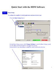
Create successful ePaper yourself
Turn your PDF publications into a flip-book with our unique Google optimized e-Paper software.
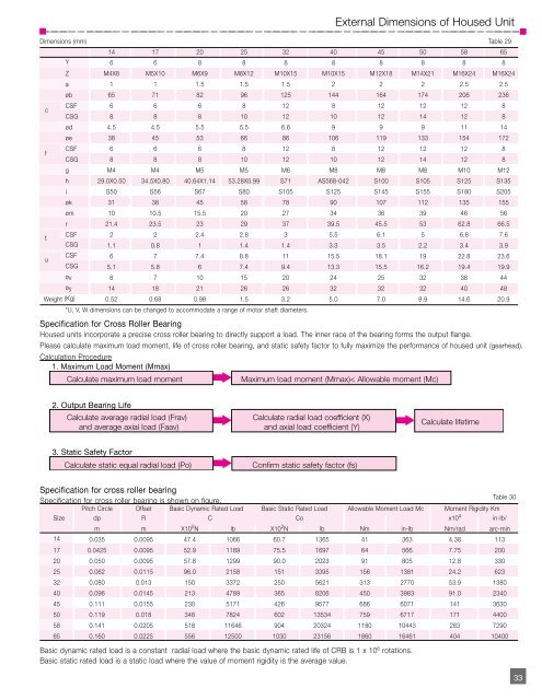
External Dimensions of Housed UnitDimensions (mm) Table 2914 17 20 25 32 40 45 50 58 65Y 6 6 8 8 8 8 8 8 8 8Z M4X8 M5X10 M6X9 M8X12 M10X15 M10X15 M12X18 M14X21 M16X24 M16X24a 1 1 1.5 1.5 1.5 2 2 2 2.5 2.5øb 65 71 82 96 125 144 164 174 206 236c<strong>CSF</strong> 6 6 6 8 12 8 12 12 12 8<strong>CSG</strong> 8 8 8 10 12 10 12 14 12 8ød 4.5 4.5 5.5 5.5 6.6 9 9 9 11 14øe 38 45 53 66 86 106 119 133 154 172f<strong>CSF</strong> 6 6 6 8 12 8 12 12 12 8<strong>CSG</strong> 8 8 8 10 12 10 12 14 12 8g M4 M4 M5 M5 M6 M8 M8 M8 M10 M12h 29.0X0.50 34.5X0.80 40.64X1.14 53.28X0.99 S71 AS568-042 S100 S105 S125 S135i S50 S56 S67 S80 S105 S125 S145 S155 S180 S205øk 31 38 45 58 78 90 107 112 135 155øm 10 10.5 15.5 20 27 34 36 39 46 56r 21.4 23.5 23 29 37 39.5 45.5 53 62.8 66.5t<strong>CSF</strong> 2 2 2.4 2.8 3 5.5 6.1 5 6.8 7.6<strong>CSG</strong> 1.1 0.8 1 1.4 1.4 3.3 3.5 2.2 3.4 3.9u<strong>CSF</strong> 6 7 7.4 8.8 11 15.5 18.1 19 22.8 23.6<strong>CSG</strong> 5.1 5.8 6 7.4 9.4 13.3 15.5 16.2 19.4 19.9øv 8 7 10 15 20 24 25 32 38 44øy 14 18 21 26 26 32 32 32 40 48Weight (Kg) 0.52 0.68 0.98 1.5 3.2 5.0 7.0 8.9 14.6 20.9*U, V, W dimensions can be changed to accommodate a range of motor shaft diameters.Specification for Cross Roller BearingHoused units incorporate a precise cross roller bearing to directly support a load. The inner race of the bearing forms the output flange.Please calculate maximum load moment, life of cross roller bearing, and static safety factor to fully maximize the performance of housed unit (gearhead).Calculation Procedure1. Maximum Load Moment (Mmax)Calculate maximum load momentMaximum load moment (Mmax)< Allowable moment (Mc)2. Output Bearing LifeCalculate average radial load (Frav)and average axial load (Faav)Calculate radial load coefficient (X)and axial load coefficient (Y)Calculate lifetime3. Static Safety FactorCalculate static equal radial load (Po)Confirm static safety factor (fs)Specification for cross roller bearingSpecification for cross roller bearing is shown on figure.Pitch Circle Offset Basic Dynamic Rated Load Basic Static Rated Load Allowable Moment Load Mc Moment Rigidity KmSize dp R C Co x10 4 in-lb/m m X10 2 N lb X10 2 N lb Nm in-lb Nm/rad arc-min14 0.035 0.0095 47.4 1066 60.7 1365 41 363 4.38 11317 0.0425 0.0095 52.9 1189 75.5 1697 64 566 7.75 20020 0.050 0.0095 57.8 1299 90.0 2023 91 805 12.8 33025 0.062 0.0115 96.0 2158 151 3395 156 1381 24.2 62332 0.080 0.013 150 3372 250 5621 313 2770 53.9 138040 0.096 0.0145 213 4789 365 8206 450 3983 91.0 234045 0.111 0.0155 230 5171 426 9577 686 6071 141 363050 0.119 0.018 348 7824 602 13534 759 6717 171 440058 0.141 0.0205 518 11646 904 20324 1180 10443 283 729065 0.160 0.0225 556 12500 1030 23156 1860 16461 404 10400Basic dynamic rated load is a constant radial load where the basic dynamic rated life of CRB is 1 x 10 6 rotations.Basic static rated load is a static load where the value of moment rigidity is the average value.Table 3033