CSF CSG PDF - Harmonic Drive LLC
CSF CSG PDF - Harmonic Drive LLC
CSF CSG PDF - Harmonic Drive LLC
- No tags were found...

Create successful ePaper yourself
Turn your PDF publications into a flip-book with our unique Google optimized e-Paper software.
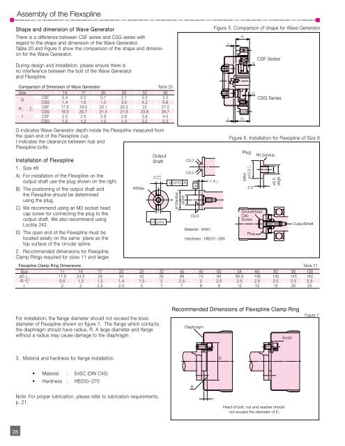
Assembly of the FlexsplineShape and dimension of Wave GeneratorThere is a difference between <strong>CSF</strong> series and <strong>CSG</strong> series withregard to the shape and dimension of the Wave Generator.Table 20 and Figure 5 show the comparison of the shape and dimensionfor the Wave Generator.During design and installation, please ensure there isno interference between the bolt of the Wave Generatorand Flexspline.Figure 5. Comparison of shape for Wave GeneratorH 1tG<strong>CSF</strong> SeriesComparison of Dimension of Wave Generator Table 20Size 14 17 20 25 32 40G<strong>CSF</strong> 0.4 0.3 0.1 2.1 2.5 3.3<strong>CSG</strong> 1.4 1.6 1.5 3.5 4.2 5.6H1 – 0 <strong>CSF</strong> 17.6 19.5 20.1 20.2 22 27.50.1<strong>CSG</strong> 18.5 20.7 21.5 21.6 23.6 29.7t <strong>CSF</strong> 2.5 2.5 2.9 2.8 3.8 4.5<strong>CSG</strong> 1.6 1.3 1.5 1.4 2.2 2.3G indicates Wave Generator depth inside the Flexspline measured fromthe open end of the Flexspline cup.t indicates the clearance between hub andFlexspline bolts.Installation of Flexspline1. Size #8A) For installation of the Flexspline on theoutput shaft use the plug shown on the right.B) The positioning of the output shaft andthe Flexspline should be determinedusing the plug.C) We recommend using an M3 socket headcap screw for connecting the plug to theoutput shaft. We also recommend usingLoctite 242.D) The open end of the Flexspline must belocated axially on the same plane as thetop surface of the circular spline.2. Recommended dimensions for FlexsplineClamp Rings required for sizes 11 and larger.M3 tapOutputShaft3 –0.005–0.015// 0.010÷ 0.010 Aø12 and upø6H6C0.2C0.2AC0.3Material : S45C1.4 0–0.1Hardness : HB201~269tH 1Plug0.1MAX.ø12.3 02.5GSocket HeadCapScrewPlug<strong>CSG</strong> SeriesFigure 6. Installation for Flexspline of Size 8R0.2 and upø3.5ø6g6Output ShaftFlexspline Clamp Ring Dimensions Table 21Size 11 14 17 20 25 32 40 45 50 58 65 80 90 100øD-0.1 017.8 24.5 29 34 42 55 68 74 83 95.8 106 130 145 162R +0.100.5 1.2 1.2 1.4 1.5 2 2.5 2 2.5 2.5 2.5 2.5 2.5 2.5t 2 2 2.5 2.5 5 7 7 8 8 12 12 15 20 25 0For installation, the flange diameter should not exceed the bossdiameter of Flexspline shown on figure 7. The flange which contactsthe diaphragm should have radius, R. A large diameter and flangewithout a radius may cause damage to the diaphragm.Recommended Dimensions of Flexspline Clamp RingDiaphragmAvoidFigure 73. Material and hardness for flange installation.D• Material : S45C (DIN C45)• Hardness : HB200~270RNote: For proper lubrication, please refer to lubrication requirements,p. 21.tHead of bolt, nut and washer shouldnot exceed the diameter of D.28