Improved Fischer-Tropsch Economics Enabled by Microchannel ...
Improved Fischer-Tropsch Economics Enabled by Microchannel ...
Improved Fischer-Tropsch Economics Enabled by Microchannel ...

You also want an ePaper? Increase the reach of your titles
YUMPU automatically turns print PDFs into web optimized ePapers that Google loves.
<strong>Improved</strong> <strong>Fischer</strong>-<strong>Tropsch</strong> <strong>Economics</strong> <strong>Enabled</strong><br />
<strong>by</strong> <strong>Microchannel</strong> Technology<br />
Steve LeViness 1 , A.L. Tonkovich 1 , Kai Jarosch 1 , Sean Fitzgerald 1 , Bin Yang 1 , Jeff McDaniel 1<br />
1. Velocys, Inc., 7950 Corporate Blvd., Plain City, Ohio 43064, USA<br />
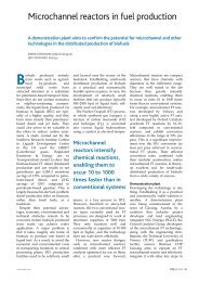
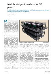
<strong>Microchannel</strong> process technology offers process intensification, in the form of enhanced heat and mass transfer, to a wide range of<br />
chemical reactions. This paper describes the application of microchannel technology to the exothermic <strong>Fischer</strong>-<strong>Tropsch</strong> (FT) process,<br />
which converts synthesis gas into a petroleum replacement – synthetic crude or fuels. Synthesis gas to feed the FT unit can be derived from<br />
a variety of feedstock materials, including natural gas and biomass. By greatly reducing the size and improving process economics,<br />
microchannel process technology enables cost effective production of synthetic fuels from smaller scale facilities, appropriate for biomass<br />
resources as well as offshore and distributed on shore natural gas resources.<br />
Introduction<br />
Sustained high oil prices, concern about global climate<br />
change, and the drive for energy security have intensified<br />
attention on alternative fuels, including those produced from<br />
<strong>Fischer</strong>-<strong>Tropsch</strong> (FT) based processes. Although some very<br />
large stranded natural gas and coal resources warrant the<br />
construction of world-scale FT synthetic fuels facilities,<br />
many applications call for smaller scale plants, including<br />
offshore and distributed gas-to-liquids (GTL), as well as<br />
biomass-to-liquids (BTL) and waste-to-liquids<br />
opportunities. The concept of producing synthetic fuels in<br />
compact units hinges on the ability to economically scaledown<br />
reaction hardware while maintaining sufficient<br />
capacity. By greatly reducing the size and improving<br />
process economics, microchannel process technology holds<br />
the potential to enable cost effective production of synthetic<br />
fuels in smaller scale facilities.<br />
<strong>Fischer</strong>-<strong>Tropsch</strong> Process and Products<br />
The FT process was first developed <strong>by</strong> Franz <strong>Fischer</strong><br />
and Hans <strong>Tropsch</strong> in Germany in the 1920s and 1930s. The<br />
chemistry is based on making longer chain hydrocarbons<br />
from a mixture of carbon monoxide (CO) and hydrogen<br />
(H 2 ), referred to as “synthesis gas”, at an elevated pressure<br />
and temperature and in the presence of a catalyst. In theory,<br />
any source of carbon can be used to generate the synthesis<br />
gas. The process is highly exothermic and excess heat from<br />
the reaction is typically removed <strong>by</strong> boiling water inside or<br />
outside reactor tubes.<br />
The majority of the products from FT synthesis are<br />
paraffinic waxes based on the following chemical equation.<br />
this century, there has been a renewed interest in synthetic<br />
fuels for the following reasons:<br />
1. Concerns about conventional oil production reaching a<br />
plateau have intensified interest in unconventional<br />
sources, such as tar sands, GTL and BTL.<br />
2. Drive for cleaner burning fuels favors synthetic<br />
products that are free of soot-forming aromatics and<br />
other non-hydrocarbon contaminants<br />
3. Vast natural gas reserves are considered “stranded,”<br />
with no viable local uses or means of transportation;<br />
these resources can be used to produce liquid fuels in an<br />
FT process.<br />
4. Concerns regarding greenhouse gas emissions have<br />
increased interest in fuels derived from renewable, nonfood<br />
biomass feedstocks.<br />
<strong>Microchannel</strong> Process Technology<br />
Systems based on microchannel process technology<br />
have the potential to transform the energy and chemical<br />
processing industries <strong>by</strong> greatly reducing the size of<br />
chemical reactor hardware. This technology has many<br />
parallels with the microelectronics that revolutionized the<br />
computer industry because it can shrink processing<br />
hardware while improving performance. Devices using<br />
microchannel technology are characterized <strong>by</strong> parallel<br />
arrays of microchannels, with typical dimensions in the 0.1<br />
to 5.0 mm range. Processes are accelerated 10 to 1,000 fold<br />
<strong>by</strong> reducing heat and mass transfer distances, thus<br />
decreasing transfer resistance between process fluids and<br />
channel walls, see Table 1. System volumes can be reduced<br />
10-fold or more compared with conventional hardware.[2]<br />
nCO + (2n+1)H 2 → C n H 2n+2 + H 2 O (1)<br />
Typical <strong>by</strong>products are liquefied petroleum gas (LPG)<br />
and naphtha. After the FT process, heavier hydrocarbons<br />
can be hydrocracked to produce distillate products, notably<br />
diesel and jet fuels.[1]<br />
FT derived transportation fuels are typically referred to<br />
as synthetic fuels. During the 20th century, these fuels were<br />
derived from coal in situations where petroleum was not<br />
readily available, such as Germany in WWII and South<br />
Africa during apartheid. However, since the beginning of<br />
Table 1. <strong>Microchannel</strong> process technology offers enhanced heat<br />
and mass transfer<br />
units <strong>Microchannel</strong> Conventional<br />
Heat Transfer<br />
Convective W/cm 2 1-20
methane reforming. The heat generated in exothermic<br />
reactions or required for endothermic reactions must be<br />
efficiently transferred across reactor walls to maintain an<br />
optimal and uniform temperature so as to achieve the<br />
highest catalytic activity and the longest catalyst life.<br />
Conventional reactor systems use massive hardware to<br />
manage the heat in such reactions.<br />
<strong>Microchannel</strong> Fouling. Claims <strong>by</strong> microchannel<br />
practitioners are often met with skepticism from industry,<br />
and this commonly includes concerns about the plugging or<br />
fouling of the thousands of small channels inside each<br />
microchannel devices. While this is a legitimate worry,<br />
experiments show that two interrelated strategies help<br />
mitigate the risk of plugging: 1) high wall shear, and<br />
2) good flow distribution.<br />
Long duration microchannel vaporizer experiments<br />
were run with and without good flow distribution. For the<br />
devices with good flow distribution, no pressure drop<br />
increases were observed in runs ranging from 1,000 to<br />
9,000 hours at both ambient and high pressure conditions.<br />
The lack of pressure drop increases held true even when the<br />
feed water was intentionally doped with low levels of<br />
dissolved solids. However, higher levels did cause fouling,<br />
as is the case for plate-frame and other types of narrow<br />
passage heat exchangers. The ability of microchannel<br />
devices to handle any amount of solids is attributed to high<br />
wall shear that sweeps particles out instead of allowing them<br />
to build-up. This was verified with post operational<br />
autopsies that did show some fouling in the headers and<br />
footers, but they were sufficiently large as not to affect<br />
pressure drop or heat transfer performance.[3]<br />
Manufacturing Techniques. <strong>Microchannel</strong> development<br />
efforts have gone beyond the process design methodology to<br />
include the manufacturing techniques for devices that<br />
commonly operate at elevated temperatures and pressures.<br />
The selected process, known as laminate fabrication,<br />
provides cost effectiveness, tight tolerances and design<br />
flexibility for microchannel reactors which commonly<br />
accommodate a complex suite of chemical unit operations in<br />
a single device. Laminate construction involves forming<br />
many parallel microchannels <strong>by</strong> interleaving (stacking) thin<br />
sheets of formed material (shims) with solid sheets (walls).<br />
The steps of this process are shown in Figure 1.<br />
Shim<br />
Feature<br />
Creation<br />
Stacking<br />
<strong>Microchannel</strong> FT Reactor Technology<br />
The microchannel FT reactor system is an example of<br />
“process intensification”, where<strong>by</strong> the reactor volume to<br />
produce a given amount of product is reduced <strong>by</strong> an order of<br />
magnitude or more. This is possible due to the enhanced<br />
heat and mass transfer capabilities of microchannel<br />
architecture, in conjunction with a highly active cobaltbased<br />
catalyst.[4,5] As shown in Figure 2, each reactor<br />
block has thousands of process channels filled with FT<br />
catalyst interleaved with water filled coolant channels.<br />
Water<br />
CO + 2H 2<br />
Water/Steam<br />
0.1 – 10.0 mm<br />
0.1 – 10.0 mm<br />
-(CH 2 )n- + H 2 O<br />
Figure 2. <strong>Microchannel</strong> FT reactor schematic<br />
Multiple microreactors are manifolded in parallel to<br />
achieve commercially significant production volumes.<br />
Modularity allows for installations to be arranged in<br />
multiple configurations that permit either a smaller footprint<br />
or lower profile than conventional FT reactors, which can be<br />
as large as 9 m in diameter and stand 60m tall.<br />
Experimental Results. The testing of an integrated<br />
microchannel FT pilot reactor, shown in Figure 3, was first<br />
completed in January of 2007. This reactor had 40 process<br />
and 425 coolant microchannels.<br />
Cross Flow Design<br />
Partial Boiling Water Coolant<br />
Process length ~ 0.6 m<br />
Process microchannels = 40<br />
Coolant Length ~ 0.3 m<br />
Coolant microchannels = 425<br />
Nominal Capacity = ~ 7 lit/day<br />
Process In<br />
Coolant In<br />
Coolant Out<br />
Process Out<br />
Figure 3. Pilot-scale microchannel FT reactor<br />
Joining<br />
Machining<br />
Figure 1. Laminate microchannel fabrication process<br />
The performance of a pilot reactor during a long<br />
duration run is shown in Figure 4. The two key numbers are<br />
the conversion of CO, and selectivity to methane. The<br />
steady state CO conversion was over 70%. The reactor<br />
operated steadily and had minimal change in conversion<br />
level during the 1,100 hour run.<br />
Velocys © 2011 Page 2 of 7
Conversion, Selectivity (%)<br />
100%<br />
90%<br />
80%<br />
70%<br />
60%<br />
50%<br />
40%<br />
30%<br />
20%<br />
10%<br />
CO Conversion<br />
CH4 Selectivity<br />
Temperature<br />
370<br />
350<br />
330<br />
310<br />
290<br />
270<br />
250<br />
230<br />
210<br />
190<br />
Temperature (°C)<br />
0%<br />
0 200 400 600 800 1000<br />
Time on stream (hr)<br />
Figure 4. <strong>Microchannel</strong> FT reactor demonstrated equivalent of 28<br />
- 44 bpd for a full-scale reactor<br />
170<br />
Selectivity to methane, also known as methane make,<br />
was approximately 9%. Methane production is<br />
counterproductive and should be minimized. The 9%<br />
methane make is on par with competing fixed bed FT<br />
technologies. The reactor was operated at conditions that<br />
correlated to commercial scale reactor capacities of 28 to<br />
44 bpd. The anticipated capacity for initial commercial<br />
rectors is 30 bpd.<br />
Process Scale-up. While several R&D groups around the<br />
world have shown the potential of microchannel reactors for<br />
process intensification, few have been successful in<br />
developing the technology for industrial scale applications.<br />
At Velocys this effort, begun in 1998, spanned several key<br />
scale-up steps, and recently culminated in fabricating a full<br />
scale reactor, the device shown in Figure 6. If operated, this<br />
reactor would have a nominal capacity of 30 bpd. The key<br />
scale-up steps are summarized in Table 2. Note, the Brazil<br />
GTL reactor has been built, accepted <strong>by</strong> the process<br />
fabricator and is expected to start-up in third quarter 2011.<br />
Table 2. <strong>Microchannel</strong> FT process scale-up<br />
Type/Units Size Year Run Time<br />
Catalyst<br />
N/A 1998- 1,200 hr<br />
development<br />
2003<br />
Full length with 24” long 2003 600 hr<br />
oil cooling<br />
Integrated pilot 12”x 24”x 2006 1,200 hr<br />
water cooled 0.5”<br />
2/3 scale 19 bpd 2008 mfg. test<br />
fabrication test<br />
Güssing field<br />
demonstration<br />
25 gal/day 2010 Now<br />
operating<br />
Full-scale<br />
fabrication test<br />
30 bpd<br />
see below<br />
2010 mfg. test<br />
Brazil GTL<br />
demonstration<br />
6 bpd 2011 6 months<br />
planned<br />
Figure 5. Commercial microchannel manufacturing techniques<br />
validated<br />
No manufacturing scale-up is required beyond this<br />
stage. In fact, the first commercial full-scale reactors were<br />
ordered in late 2010 for delivery in mid-2011.<br />
FT Catalyst. The most common metals used to catalyze FT<br />
are cobalt and iron. Cobalt-based catalysts are known for<br />
their higher activity and longer life. For this reason, FT<br />
reactors using iron based catalyst must either be larger or<br />
require more frequent catalyst replacement than those using<br />
cobalt. So, nearly all fixed bed reactors technologies employ<br />
cobalt catalyst, including microchannel FT. Because catalyst<br />
replacement is easier in slurry bed reactors, they can use<br />
either iron or cobalt catalyst. All FT catalysts are sensitive<br />
to poisoning <strong>by</strong> sulfur-containing compounds, and every<br />
effort must be made to clean these from the syngas before<br />
entering the FT reactor.<br />
An FT catalyst developed <strong>by</strong> Oxford Catalysts Group<br />
enables microchannel reactors to achieve catalyst<br />
productivities that are orders of magnitude higher than for<br />
more conventional systems (see Figure 6). A demonstration<br />
carried out in 2008 in a nominal two-gallon per day<br />
microchannel reactor operated for more than 4,000 hours<br />
and achieved productivities of more than 1500 kg/m3/h. In<br />
contrast, conventional fixed-bed reactors typically operate at<br />
100 kg/m3/h, while slurry-bed reactors operate at<br />
200 kg/m3/h.<br />
Velocys © 2011 Page 3 of 7<br />
Catalyst Productivity (kg/m 3 /hr) (kg/m 3 /hr)<br />
1600<br />
1400<br />
1200<br />
1000<br />
800<br />
600<br />
400<br />
200<br />
0<br />
Fixed Bed Slurry Bed<br />
<strong>Microchannel</strong> Velocys<br />
Figure 6. <strong>Microchannel</strong> FT achieves far higher catalyst<br />
productivity
In the absence of contaminants, there are two types of<br />
catalyst deactivation in FT synthesis: 1) short-term<br />
deactivation caused <strong>by</strong> wax build-up and/or partial oxidation<br />
of the cobalt catalyst particles, and 2) longer term<br />
deactivation, which involves sintering, loss of pore structure<br />
and/or build-up of refractory carbon. The first is reversible;<br />
the second may be reversible under certain conditions, but<br />
could require replacing the catalyst. For short-term<br />
deactivation, in situ hydrotreating was shown to be effective<br />
at restoring catalyst activity. Figure 7 displays reactor<br />
performance data at the same conditions before and after<br />
regeneration.<br />
Conversion, Selectivity (%)<br />
100%<br />
90%<br />
80%<br />
70%<br />
60%<br />
50%<br />
40%<br />
30%<br />
20%<br />
Regeneration<br />
CO Conversion<br />
CH4 Selectivity<br />
Temperature<br />
370<br />
350<br />
330<br />
310<br />
290<br />
270<br />
250<br />
230<br />
210<br />
Temperature (°C)<br />
segregated <strong>by</strong> sequential condensation. In Shell’s fixed bed<br />
design, catalyst is packed into small tubes inside a large<br />
diameter vessel with means to remove heat <strong>by</strong> boiling water<br />
around the tubes. To maintain a reasonable pressure drop,<br />
catalyst particles in conventional fixed bed reactors are<br />
relatively large, in the range of 1 mm. This often limits the<br />
rate of reaction and leads to higher than desired selectively<br />
to methane.[7]<br />
<strong>Microchannel</strong> FT reactor technology provides<br />
substantial techno-economic benefits over conventional<br />
fixed bed technology, including:<br />
1) <strong>Microchannel</strong> FT has thin reaction channels, 1 to<br />
2 orders of magnitude smaller characteristic dimensions in<br />
competing fixed bed designs. This attribute greatly<br />
improves heat and mass transfer, allowing optimal<br />
temperature control across the catalyst bed, and leads to far<br />
higher reactor productivity. Figure 8 shows reactor<br />
productivity, defined as barrels/day of FT product per ton of<br />
reactor mass compared to large-scale FT reactor systems.<br />
Both Shell data points are fixed bed designs, while Sasol<br />
Oryx uses slurry bed reactors.<br />
10%<br />
190<br />
12<br />
0%<br />
0 500 1000<br />
170<br />
2000 2500<br />
Time on Stream (hr)<br />
Figure 7. <strong>Microchannel</strong> FT in-situ regeneration shown effective at<br />
recovering performance<br />
Catalyst Integration. Placing catalyst in packed bed<br />
reactors can be a challenge for any technology.<br />
Conventional FT reactors have as many as 29,000 small (1”)<br />
diameter tubes 12m in length, which must be equally loaded<br />
and then unloaded after 2 to 5 years of operation.[6] These<br />
high aspect ratio (over 500:1 length to diameter) tubes are<br />
hung in very large, immobile reactors, but commercial<br />
integration techniques have been shown effective for<br />
loading and unloading the catalyst. Because microchannel<br />
technology has extremely small passages, many expect<br />
catalyst loading and unloading to be especially challenging,<br />
but this was found not to be the case.<br />
Catalyst loading, regeneration and unloading for<br />
microchannel FT reactors have been successfully<br />
demonstrated. Multiple operating and non-operating<br />
reactors with commercial length microchannels (aspect ratio<br />
385:1 length to hydraulic diameter) have been repeatedly<br />
loaded and unloaded. A mechanical loading method is<br />
employed using commercially available material handling<br />
techniques and equipment.<br />
Comparison with Competing FT Technologies<br />
Due to improved volumetric and catalytic productivity,<br />
microchannel FT enables lower capital and operating costs<br />
compared to conventional FT reactor systems, including<br />
tubular, fixed-bed with cobalt catalyst, and slurry-bubble<br />
with cobalt or iron catalyst.<br />
Fixed Bed. In a conventional (tubular) fixed bed designs, all<br />
reaction products exit through a single outlet, leaving the<br />
catalyst behind in the reactor. The resulting products are<br />
0<br />
0 2,000 4,000 6,000 8,000 10,000 12,000<br />
Scale of Single Reactor (bpd)<br />
Velocys © 2011 Page 4 of 7<br />
Reactor Productivity (bpd/tonne)<br />
10<br />
8<br />
6<br />
4<br />
2<br />
300 bpd <strong>Microchannel</strong><br />
Reactor Assembly<br />
Shell - Bintulu<br />
Shell - Pearl<br />
Sasol - Oryx<br />
Figure 8. <strong>Microchannel</strong> FT improves reactor productivity and<br />
achieves economy of scale at far lower capacity<br />
<strong>Microchannel</strong> FT also achieves approximately 10 times<br />
higher catalyst productivity, defined as kg/hr of synthesis<br />
gas processed per cubic meter of catalyst volume. Both<br />
capital and operating costs are thus reduced.<br />
2) The basic building blocks of the microchannel FT<br />
reactor systems are components with thousands of parallel<br />
microchannels. These reactor components, which have fixed<br />
production capabilities, can be added or removed to match<br />
throughput requirements. When this modular design<br />
approach is combined with process intensification benefits<br />
discussed above, two advantages are realized:<br />
a. <strong>Microchannel</strong> FT realizes economies of scale at<br />
much smaller size (500 bpd) than conventional technology<br />
(10,000 bpd). This advantage allows microchannel FT to be<br />
feasible for BTL applications since it is not practical to<br />
transport the required biomass feedstock of 10,000 tons/day<br />
for a 10,000 bpd facility. The smaller economy of scale also<br />
permits feasibility for distributed and offshore GTL.
. Since the basic reactor modules are small, reactor<br />
and FT unit fabrication can take place at indoor shops,<br />
which speeds construction and installation. On the other<br />
hand, commercial-scale conventional reactors are large and<br />
must be placed in ‘stick built’ facilities that have relatively<br />
long construct timelines.<br />
3) The modular approach of microchannel FT helps<br />
minimize downtime due to individual modules needing<br />
components or catalysts to be replaced. Conventional fixed<br />
bed systems require an entire train or system shutdown to<br />
make changes or repairs. Because microchannel FT reactors<br />
are smaller the impact of taking a one or a few out of<br />
operation does not materially impact the facilities overall<br />
productivity.<br />
Slurry Bed. In slurry bed reactors, a heavy hydrocarbon<br />
liquid is used to suspend the catalyst and the heavier<br />
products remain in the reactor while the light ones are<br />
removed as vapors overhead as shown in Figure 9. A<br />
portion of the liquid mixture is continuously removed to<br />
recover the heavy hydrocarbon products, while the carrier<br />
liquid and majority of the catalyst are recycled back to the<br />
reactor. Removing small particles of catalyst, known as<br />
fines, from the wax is a significant challenge, and<br />
sometimes wax products from slurry bed processes are grey,<br />
instead of white, due to the presence of catalyst fines. This<br />
lowers the value of FT wax because final separation for<br />
chemical uses can be expensive.[8]<br />
Compared to commercial slurry bed sytems,<br />
microchannel FT offers a compact equipment footprint<br />
and/or lower profile. <strong>Microchannel</strong> reactor assemblies are<br />
relatively small and can be situated horizontally versus<br />
conventional slurry bed FT reactors that are vertically<br />
oriented and can be more than 60m tall. Figure 10 compares<br />
the size of a microchannel reactor assembly with a<br />
ConocoPhillips demonstration plant of similar capacity.<br />
ConocoPhillips<br />
400 bpd demo<br />
plant<br />
Velocys 300 bpd<br />
reactor assembly<br />
Vapor product<br />
Slurry Bubble<br />
Zone<br />
(small catalyst<br />
particles)<br />
Vapor<br />
Zone<br />
Liquid product<br />
Catalyst/<br />
Wax<br />
Separator<br />
Figure 10. Small size and low profile eases installation and<br />
operation in offshore environments<br />
Commercial Applications<br />
Since conventional FT technologies are not<br />
economically viable at small scale, below 10,000 bpd, the<br />
current focus for FT planning and installation projects are<br />
large land-based natural gas fields, such as those in Qatar.<br />
Boiler Feed<br />
Water<br />
Catalyst<br />
Return<br />
Figure 9. Slurry bed reactor schematic<br />
-<br />
Syngas<br />
Slurry bed reactors do have operational advantages,<br />
including the ability to change the catalyst without shutting<br />
down the system. However, due to their relative complexity<br />
compared to fixed bed designs, slurry bed reactors are<br />
typically best suited for very large-scale operations.<br />
Furthermore, this complexity leads to poor process<br />
economics when slurry bed systems are scaled down for<br />
distributed synthetic fuel operations.<br />
Biomass-to-Liquids. Biomass feedstock materials are not<br />
easily aggregated and transportation costs to large BTL<br />
plants are high. <strong>Microchannel</strong> FT can overcome these<br />
challenges <strong>by</strong> economically operating small (500-2,000 bpd)<br />
plants that require about 500-2,000 tpd of biomass. These<br />
synthesis gas generation plus FT synthesis facilities can then<br />
be located near low-cost, biomass sources. The heavy<br />
hydrocarbon products can then be economically shipped to<br />
central upgrading (refining) facilities since the FT product<br />
density is much higher than that of biomass.<br />
The feedstock choices for FT are non-food biomass,<br />
such as forest residues, agricultural residue, municipal solid<br />
waste (MSW), and construction and demolition waste<br />
(CDW). Based on the U.S Department of Energy (DOE)<br />
estimates and data on waste sent to landfills, the domestic<br />
biomass supply is large enough to replace more than half of<br />
petroleum-based distillate fuel demand [11] as shown in<br />
Figure 11.<br />
Velocys © 2011 Page 5 of 7
Billions of Gallons/Year<br />
100<br />
90<br />
80<br />
70<br />
60<br />
50<br />
40<br />
30<br />
Current Demand<br />
MSW/CDW<br />
Forest<br />
viable sources. See Figure 12. <strong>Microchannel</strong> FT permits<br />
economic production at this smaller scale.[14]<br />
Another advantage of microchannel FT technology is<br />
that it enables facilities to be placed on offshore structures.<br />
A conceptual sketch of such a plant is shown in Figure 13.<br />
20<br />
10<br />
Agricultural<br />
0<br />
Figure 11. U.S. demand for distillate fuel versus biomass available<br />
for conversion to FT fuels<br />
Offshore Gas to Liquids. Natural gas without access to the<br />
world market is known as “stranded gas.” This includes<br />
large reserves in remote places and associated gas that is coproduced<br />
with oil. The quantity of stranded gas is estimated<br />
to be between 900 and 9,000 trillion cubic feet in<br />
volume,[12,13] which is sufficient to supply current level of<br />
U.S. distillate fuels demand for more than 300 years.<br />
As noted above, natural gas is either co-produced with<br />
petroleum or sits on top of petroleum reservoirs. With no<br />
local market for this gas, oil production is not possible<br />
without venting, flaring or reinjection of this gas back into<br />
the reservoir. Due to concern about safety, resource<br />
conservation and greenhouse gas emissions, venting and<br />
continuous flaring are banned or highly discouraged in<br />
nearly all oil producing regions of the world. This leaves<br />
reinjection, which currently cost up to $13 per equivalent<br />
barrel of petroleum, and these costs are highest offshore. A<br />
better solution is to convert this gas into liquid fuels in a FT<br />
process.<br />
Figure 13. Concept GTL facility on Floating Production Storage<br />
and Offloading (FPSO) vessel<br />
Stage of Development<br />
As of early 2011, microchannel FT technology is entering<br />
the final stages of commercialization. In 2010, a successful<br />
field demonstration of a 25 gal/day rector was conducted at<br />
a biomass gasification plant in Güssing, Austria. The<br />
skidded FT unit for the Austrian demonstration is shown in<br />
Figure 14. A second demonstration, slated for 2011 in<br />
Brazil, will be of an integrated GTL process, which includes<br />
both microchannel FT and microchannel steam methane<br />
reforming (SMR).<br />
Conventional<br />
LNG / GTL<br />
4 >50 (in tcf)<br />
73 5-50<br />
337 1-5<br />
<strong>Microchannel</strong><br />
GTL<br />
347<br />
719<br />
1,043<br />
0.5-1<br />
0.25-0.5<br />
0.1-0.25<br />
3,922 gas fields
into ultra-clean transportation fuels. Of the potential raw<br />
materials used for alternative fuels, biomass and stranded<br />
natural gas are seen as the most attractive due to their<br />
abundance and potential for low life cycle carbon emissions.<br />
Furthermore, the application of microchannel technology to<br />
FT enables cost effective production at the smaller-scales<br />
appropriate for BTL and offshore and distributed GTL<br />
facilities.<br />
First generation biofuels, including corn ethanol and<br />
biodiesel, are prevalent today, but are seen as only an<br />
interim solution due to their use of food crops for raw<br />
material. Next generation biofuels, ones that use non-food<br />
biomass, are a more sustainable choice. Systems based on<br />
microchannel FT produce high quality, energy dense fuel<br />
from a wide variety of resources, including waste wood,<br />
energy crops and municipal solid waste. Furthermore, they<br />
permit favorable economics for smaller-scale facilities,<br />
suitable for next generation biofuels.<br />
Due to ever stricter flaring regulations, associated<br />
natural gas is typically seen as a cost of oil exploration and<br />
production because of the capital equipment and energy<br />
required to re-inject the gas back into the reservoir. The cost<br />
of associated gas is highest offshore, where drilling wells<br />
and installing equipment are more expensive, and deck<br />
space is at a premium. The opportunity lies in the ability to<br />
monetize the natural gas through a FT based GTL process<br />
enabled <strong>by</strong> microchannel technology; there<strong>by</strong>, transforming<br />
the burden of associated gas into a valuable resource that<br />
increases revenues and stretches reserves. The process<br />
intensification possible with microchannel FT improves<br />
volumetric productivity and efficiency, improving process<br />
economics and shrinking facility footprints, which are<br />
essential for offshore facilities.<br />
[10] Energy Independence and Security Act of 2007, Public<br />
Law 110-140, 110th Congress, Signed December 19,<br />
2007<br />
[11] L. Wright, B. Boundy, B. Perlack, S. Davis, B.<br />
Saulsbury, Biomass Energy Data Book: Edition 1,<br />
September 2006<br />
[12] Petroconsultants-MIA and Zeus International, Remote<br />
Gas Development Strategies, HIS Energy Services,<br />
September 1999.<br />
[13] Agee, M., "Taking GTL conversion offshore," OTC<br />
10762, Offshore Technology Conference, May 3-6,<br />
1999.<br />
[14] N. Jones, T. Tveitnes, “The M-flex LNG Carrier<br />
Design”<br />
References<br />
[1] Strange, A. M.; AIChE 2003 Spring National Meeting,<br />
New Orleans, LA, 2003.<br />
[2] K. T. Jarosch, A. L. Tonkovich, S. T. Perry, D.<br />
Kuhlmann, Y. Wang, Reactors for Intensifying Gas-to-<br />
Liquid Technology, in Microreactor Technology and<br />
Process Intensification, ACS Symposium Series n 914,<br />
September 2005.<br />
[3] A. Y. Tonkovich, Y. et al, <strong>Microchannel</strong> Fouling<br />
Mitigation: Flow Distribution and Wall Shear Effects,<br />
AIChE Fall 2005<br />
[4] Y. Wang, D. P. Vanderwiel, A. Y. Tonkovich, Y. Gao<br />
E. G. Baker, US 6,451,864 2002.<br />
[5] Y. Wang, D. P. Vanderwiel, A. Y. Tonkovich, Y. Gao,<br />
E. G. Baker, US 6,558,634 2003.<br />
[6] B. Altemühl, Svetsaren: ESAB Welding and Cutting<br />
Journal, Vol. 63, No. 1 (2008), p. 51-55<br />
[7] R.L. Espinoza, A.P. Steynberg, B. Jager, A.C. Vosloo,<br />
Applied Catalysis A: General 186 (1999) 13–26<br />
[8] Font Freide, Joep J. H. M.; Collins, John P.; Nay,<br />
Barry; Sharp, Chris, American Chemical Society,<br />
Division of Petroleum Chemistry, Preprints, v 50, n 2,<br />
March, 2005, p 149-151<br />
[9] J. Bereznicki, Alter NRG Analyst Report, Paradigm<br />
Capital, April 15, 2007<br />
Velocys © 2011 Page 7 of 7