Improved Fischer-Tropsch Economics Enabled by Microchannel ...
Improved Fischer-Tropsch Economics Enabled by Microchannel ...
Improved Fischer-Tropsch Economics Enabled by Microchannel ...

You also want an ePaper? Increase the reach of your titles
YUMPU automatically turns print PDFs into web optimized ePapers that Google loves.
methane reforming. The heat generated in exothermic<br />
reactions or required for endothermic reactions must be<br />
efficiently transferred across reactor walls to maintain an<br />
optimal and uniform temperature so as to achieve the<br />
highest catalytic activity and the longest catalyst life.<br />
Conventional reactor systems use massive hardware to<br />
manage the heat in such reactions.<br />
<strong>Microchannel</strong> Fouling. Claims <strong>by</strong> microchannel<br />
practitioners are often met with skepticism from industry,<br />
and this commonly includes concerns about the plugging or<br />
fouling of the thousands of small channels inside each<br />
microchannel devices. While this is a legitimate worry,<br />
experiments show that two interrelated strategies help<br />
mitigate the risk of plugging: 1) high wall shear, and<br />
2) good flow distribution.<br />
Long duration microchannel vaporizer experiments<br />
were run with and without good flow distribution. For the<br />
devices with good flow distribution, no pressure drop<br />
increases were observed in runs ranging from 1,000 to<br />
9,000 hours at both ambient and high pressure conditions.<br />
The lack of pressure drop increases held true even when the<br />
feed water was intentionally doped with low levels of<br />
dissolved solids. However, higher levels did cause fouling,<br />
as is the case for plate-frame and other types of narrow<br />
passage heat exchangers. The ability of microchannel<br />
devices to handle any amount of solids is attributed to high<br />
wall shear that sweeps particles out instead of allowing them<br />
to build-up. This was verified with post operational<br />
autopsies that did show some fouling in the headers and<br />
footers, but they were sufficiently large as not to affect<br />
pressure drop or heat transfer performance.[3]<br />
Manufacturing Techniques. <strong>Microchannel</strong> development<br />
efforts have gone beyond the process design methodology to<br />
include the manufacturing techniques for devices that<br />
commonly operate at elevated temperatures and pressures.<br />
The selected process, known as laminate fabrication,<br />
provides cost effectiveness, tight tolerances and design<br />
flexibility for microchannel reactors which commonly<br />
accommodate a complex suite of chemical unit operations in<br />
a single device. Laminate construction involves forming<br />
many parallel microchannels <strong>by</strong> interleaving (stacking) thin<br />
sheets of formed material (shims) with solid sheets (walls).<br />
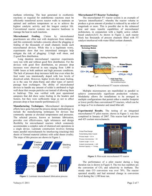
The steps of this process are shown in Figure 1.<br />
Shim<br />
Feature<br />
Creation<br />
Stacking<br />
<strong>Microchannel</strong> FT Reactor Technology<br />
The microchannel FT reactor system is an example of<br />
“process intensification”, where<strong>by</strong> the reactor volume to<br />
produce a given amount of product is reduced <strong>by</strong> an order of<br />
magnitude or more. This is possible due to the enhanced<br />
heat and mass transfer capabilities of microchannel<br />
architecture, in conjunction with a highly active cobaltbased<br />
catalyst.[4,5] As shown in Figure 2, each reactor<br />
block has thousands of process channels filled with FT<br />
catalyst interleaved with water filled coolant channels.<br />
Water<br />
CO + 2H 2<br />
Water/Steam<br />
0.1 – 10.0 mm<br />
0.1 – 10.0 mm<br />
-(CH 2 )n- + H 2 O<br />
Figure 2. <strong>Microchannel</strong> FT reactor schematic<br />
Multiple microreactors are manifolded in parallel to<br />
achieve commercially significant production volumes.<br />
Modularity allows for installations to be arranged in<br />
multiple configurations that permit either a smaller footprint<br />
or lower profile than conventional FT reactors, which can be<br />
as large as 9 m in diameter and stand 60m tall.<br />
Experimental Results. The testing of an integrated<br />
microchannel FT pilot reactor, shown in Figure 3, was first<br />
completed in January of 2007. This reactor had 40 process<br />
and 425 coolant microchannels.<br />
Cross Flow Design<br />
Partial Boiling Water Coolant<br />
Process length ~ 0.6 m<br />
Process microchannels = 40<br />
Coolant Length ~ 0.3 m<br />
Coolant microchannels = 425<br />
Nominal Capacity = ~ 7 lit/day<br />
Process In<br />
Coolant In<br />
Coolant Out<br />
Process Out<br />
Figure 3. Pilot-scale microchannel FT reactor<br />
Joining<br />
Machining<br />
Figure 1. Laminate microchannel fabrication process<br />
The performance of a pilot reactor during a long<br />
duration run is shown in Figure 4. The two key numbers are<br />
the conversion of CO, and selectivity to methane. The<br />
steady state CO conversion was over 70%. The reactor<br />
operated steadily and had minimal change in conversion<br />
level during the 1,100 hour run.<br />
Velocys © 2011 Page 2 of 7