Assembly instructions - KLARO GmbH
Assembly instructions - KLARO GmbH
Assembly instructions - KLARO GmbH

Create successful ePaper yourself
Turn your PDF publications into a flip-book with our unique Google optimized e-Paper software.
<strong>Assembly</strong> <strong>instructions</strong> <strong>KLARO</strong> UV hygienisation stage<br />
4.3. External assembly of the switching device<br />
An external assembly of the switching device is only possible in connection with an<br />
A cabinet 1, 2 or B cabinets. For the B cabinets, the switching device is fastened to the<br />
installation plate. The assembly in the A cabinet 1 and 2 is carried out in the base of the<br />
control cabinet (see below).<br />
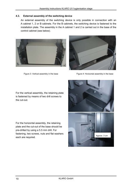
Figure 3: Vertical assembly in the base<br />
Figure 4: Horizontal assembly in the base<br />
For the vertical assembly, the retaining plate<br />
is fastened by means of two drill screws to<br />
the cut-out.<br />
For the horizontal assembly, the retaining<br />
plate and the cut-out of the base should be<br />
pre-drilled by using a 5.5 mm drill. For<br />
fastening, two screws, nuts and flat washers<br />
each are required.<br />
Approx. 3 cm<br />
10<br />
<strong>KLARO</strong> <strong>GmbH</strong>