Sustainable Construction A Life Cycle Approach in Engineering
Sustainable Construction A Life Cycle Approach in Engineering
Sustainable Construction A Life Cycle Approach in Engineering

You also want an ePaper? Increase the reach of your titles
YUMPU automatically turns print PDFs into web optimized ePapers that Google loves.
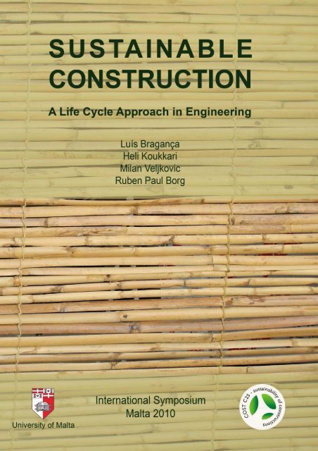
<strong>Susta<strong>in</strong>able</strong> <strong>Construction</strong><br />
A <strong>Life</strong> <strong>Cycle</strong> <strong>Approach</strong> <strong>in</strong> Eng<strong>in</strong>eer<strong>in</strong>g<br />
Proceed<strong>in</strong>gs<br />
International Symposium<br />
Malta, 23 - 25 July 2010<br />
COST Action C25<br />
Susta<strong>in</strong>ability of <strong>Construction</strong>s<br />
Integrated <strong>Approach</strong> to <strong>Life</strong>-time Structural Eng<strong>in</strong>eer<strong>in</strong>g
<strong>Susta<strong>in</strong>able</strong> <strong>Construction</strong><br />
A <strong>Life</strong> <strong>Cycle</strong> <strong>Approach</strong> <strong>in</strong> Eng<strong>in</strong>eer<strong>in</strong>g<br />
Proceed<strong>in</strong>gs<br />
International Symposium<br />
Malta, 23 - 25 July 2010<br />
Editors<br />
Luís Bragança, Heli Koukkari, Milan Veljkovic, Ruben Paul Borg<br />
COST Action C25<br />
Susta<strong>in</strong>ability of <strong>Construction</strong>s<br />
Integrated <strong>Approach</strong> to <strong>Life</strong>-time Structural Eng<strong>in</strong>eer<strong>in</strong>g<br />
Department of Build<strong>in</strong>g & Civil Eng<strong>in</strong>eer<strong>in</strong>g<br />
Faculty for the Built Environment<br />
University of Malta<br />
COST is supported by the EU RTD Framework programme. ESF provides the COST Office through an EC contract.
COST- the acronym for European COoperation <strong>in</strong> the field of Scientific and Technical Research- is the oldest<br />
and widest European <strong>in</strong>tergovernmental network for cooperation <strong>in</strong> research. Established by the M<strong>in</strong>isterial<br />
Conference <strong>in</strong> November 1971, COST is presently used by the scientific communities of 35 European countries<br />
to cooperate <strong>in</strong> common research projects supported by national funds.<br />
The funds provided by COST - less than 1% of the total value of the projects - support the COST cooperation<br />
networks (COST Actions) through which, with only around €20 million per year, more than 30.000 European<br />
scientists are <strong>in</strong>volved <strong>in</strong> research hav<strong>in</strong>g a total value which exceeds €2 billion per year. This is the f<strong>in</strong>ancial<br />
worth of the European added value which COST achieves.<br />
A “bottom up approach” (the <strong>in</strong>itiative of launch<strong>in</strong>g a COST Action comes from the European scientists<br />
themselves), “à la carte participation” (only countries <strong>in</strong>terested <strong>in</strong> the Action participate), “equality of access”<br />
(participation is open also to the scientific communities of countries not belong<strong>in</strong>g to the European Union) and<br />
“flexible structure” (easy implementation and light management of the research <strong>in</strong>itiatives ) are the ma<strong>in</strong><br />
characteristics of COST.<br />
As precursor of advanced multidiscipl<strong>in</strong>ary research COST has a very important role for the realisation of the<br />
European Research Area (ERA) anticipat<strong>in</strong>g and complement<strong>in</strong>g the activities of the Framework Programmes,<br />
constitut<strong>in</strong>g a “bridge” towards the scientific communities of emerg<strong>in</strong>g countries, <strong>in</strong>creas<strong>in</strong>g the mobility of<br />
researchers across Europe and foster<strong>in</strong>g the establishment of “Networks of Excellence” <strong>in</strong> many key scientific<br />
doma<strong>in</strong>s such as: Biomedic<strong>in</strong>e and Molecular Biosciences; Food and Agriculture; Forests, their Products and<br />
Services; Materials, Physics and Nanosciences; Chemistry and Molecular Sciences and Technologies; Earth<br />
System Science and Environmental Management; Information and Communication Technologies; Transport and<br />
Urban Development; Individuals, Society, Culture and Health. It covers basic and more applied research and<br />
also addresses issues of pre-normative nature or of societal importance.<br />
<strong>Susta<strong>in</strong>able</strong> <strong>Construction</strong>: A <strong>Life</strong> <strong>Cycle</strong> <strong>Approach</strong> <strong>in</strong> Eng<strong>in</strong>eer<strong>in</strong>g<br />
Proceed<strong>in</strong>gs - International Symposium<br />
Malta, 23 - 25 July 2010<br />
COST Action C25<br />
Susta<strong>in</strong>ability of <strong>Construction</strong>s: Integrated <strong>Approach</strong> to life-time Structural Eng<strong>in</strong>eer<strong>in</strong>g<br />
The production of this publication was supported by COST: www.cost.esf.org<br />
Editors: Luís Bragança, Heli Koukkari, Milan Veljkovic, Ruben Paul Borg<br />
Cover Design: Ruben Paul Borg (Il-ħasira, The reed screen)<br />
The content of each paper is the responsibility of the respective author/s.<br />
The papers published <strong>in</strong> this book, have been reviewed by the Scientific & Editorial Committee. The<br />
papers were presented dur<strong>in</strong>g the International Symposium, held <strong>in</strong> Malta, from the 23<br />
rd to 25 th July<br />
2010.<br />
© 2010 The Authors and The Editors<br />
All rights reserved. No part of this publication may be reproduced, stored <strong>in</strong> a retrieval system, or transmitted, <strong>in</strong><br />
any form or by any means, without prior written permission from the publisher.<br />
The Editors, the Authors and the Publisher are not responsible for the use which might be made of the<br />
<strong>in</strong>formation conta<strong>in</strong>ed <strong>in</strong> this publication.<br />
ISBN 9 7 8 9 9 9 3 2 0 9 1 7 1<br />
Publisher: Faculty for the Built Environment, University of Malta.<br />
Pr<strong>in</strong>ted <strong>in</strong> Malta by Gutenberg Press, 2010<br />
July 2010
COST Action C25<br />
Susta<strong>in</strong>ability of <strong>Construction</strong>s<br />
Integrated <strong>Approach</strong> to life-time Structural Eng<strong>in</strong>eer<strong>in</strong>g<br />
International Symposium<br />
Malta 2010<br />
The Editors:<br />
Ruben Paul Borg University of Malta, Malta<br />
Milan Veljkovic Luleå University of Technology, Sweden<br />
Heli Koukkari VTT Technical Research Centre of F<strong>in</strong>land, F<strong>in</strong>land<br />
Luís Bragança University of M<strong>in</strong>ho, Portugal<br />
v
Foreword<br />
The COST Action C25 "Susta<strong>in</strong>ability of <strong>Construction</strong>s - Integrated <strong>Approach</strong> to <strong>Life</strong>-time<br />
Structural Eng<strong>in</strong>eer<strong>in</strong>g" is a network of scientists and researchers from 28 European countries<br />
and the EU Jo<strong>in</strong>t Research Centre <strong>in</strong> Ispra. It was established to promote science-based<br />
developments <strong>in</strong> susta<strong>in</strong>able construction <strong>in</strong> Europe through research on life-time structural<br />
eng<strong>in</strong>eer<strong>in</strong>g. The Action is <strong>in</strong> its fourth year of activity.<br />
The Action concentrates on R&D issues that are fundamental for susta<strong>in</strong>able construction<br />
processes and technologies. These <strong>in</strong>clude methods to assess environmental, social and<br />
economic impacts of construction activities; methods to analyse eco-efficiency of materials,<br />
components, build<strong>in</strong>gs and <strong>in</strong>frastructures; methods to <strong>in</strong>tegrate research approaches from<br />
various discipl<strong>in</strong>es; and methods of structural design that <strong>in</strong>corporate holistic understand<strong>in</strong>g of<br />
safety, eco-efficiency and susta<strong>in</strong>ability.<br />
The Action has organised three major events, an event every year, where the f<strong>in</strong>d<strong>in</strong>gs of jo<strong>in</strong>t<br />
efforts of the Members have been discussed and published:<br />
• 1st Workshop <strong>in</strong> Lisbon, Portugal, on 13, 14 and 15 September 2007;<br />
• the Midterm Sem<strong>in</strong>ar <strong>in</strong> Dresden, Germany, on 6-7 October 2008;<br />
• International Workshop <strong>in</strong> Timisoara, Romania, on 23-24 October 2009.<br />
Some of the Action results were already applied through the dissem<strong>in</strong>ation of the life-time<br />
eng<strong>in</strong>eer<strong>in</strong>g approach to the susta<strong>in</strong>ability issues <strong>in</strong> tasks carried out by C25 members.<br />
However, a short <strong>in</strong>vestigation of university syllabuses, completed by an add-hoc C25 group on<br />
educational issues, has shown clearly the need for a new approach <strong>in</strong> teach<strong>in</strong>g structural<br />
eng<strong>in</strong>eers on susta<strong>in</strong>ability issues. One of the important aspects <strong>in</strong> fill<strong>in</strong>g this gap is the tra<strong>in</strong><strong>in</strong>g<br />
of young research students. So far, two very successful Tra<strong>in</strong><strong>in</strong>g Schools were organised:<br />
• The first Tra<strong>in</strong><strong>in</strong>g School was “The LCA Tra<strong>in</strong><strong>in</strong>g School” and was organised for 16<br />
participants <strong>in</strong> E<strong>in</strong>dhoven, Netherlands, on 13-15 February 2008. The participants were<br />
ma<strong>in</strong>ly Early Stage Researchers from C25 who could learn and deepen their knowledge<br />
on the use of <strong>Life</strong> <strong>Cycle</strong> Analysis theories and tools;<br />
• The second Tra<strong>in</strong><strong>in</strong>g School “Susta<strong>in</strong>ability <strong>in</strong> structures and structural <strong>in</strong>terventions:<br />
Improv<strong>in</strong>g the contemporary and historical urban habitat constructions with<strong>in</strong> a<br />
susta<strong>in</strong>ability and risk assessment framework” was held <strong>in</strong> Thessaloniki, Greece, on 17-<br />
24 May 2009. It was jo<strong>in</strong>tly organised by C25 and C26 and the number of Early Stage<br />
Researchers was 40, from these two Actions.<br />
The third C25 Tra<strong>in</strong><strong>in</strong>g School, organised under the theme “<strong>Susta<strong>in</strong>able</strong> <strong>Construction</strong>: A <strong>Life</strong><br />
<strong>Cycle</strong> <strong>Approach</strong> <strong>in</strong> Structural Eng<strong>in</strong>eer<strong>in</strong>g”, aims at provid<strong>in</strong>g C25 and non-C25 Early Stage<br />
Researchers and PhD students with theories, tools and assignments to address susta<strong>in</strong>ability <strong>in</strong><br />
eng<strong>in</strong>eer<strong>in</strong>g and the life-cycle approach <strong>in</strong> structural eng<strong>in</strong>eer<strong>in</strong>g.<br />
This Tra<strong>in</strong><strong>in</strong>g School is hosted by the Department of Build<strong>in</strong>g and Civil Eng<strong>in</strong>eer<strong>in</strong>g, Faculty<br />
for the Built Environment of the University of Malta and offers excellent opportunities for<br />
collaboration among the researchers.<br />
vii
The whole event consists of two complementary activities:<br />
• The International Early Stage Researchers Symposium, from the 23 rd of July till the 25 th<br />
of July 2010;<br />
• The International Tra<strong>in</strong><strong>in</strong>g School, from the 26 th of July till the 1 st of August 2010.<br />
The programme and the scientific content of the Malta Tra<strong>in</strong><strong>in</strong>g School were prepared with the<br />
support of an <strong>in</strong>ternational group of experts and were approved by the Management Committee<br />
of the COST Action C25. The group of experienced lecturers were selected to teach and<br />
supervise the group work dur<strong>in</strong>g the school.<br />
The aim of the International Early Stage Researchers Symposium is to give the opportunity to<br />
the participants to present their own work and to get an overview of the research work that is<br />
be<strong>in</strong>g done by the other researchers all around Europe. The Symposium will be also an<br />
important forum for the discussion of new ideas <strong>in</strong> the field of <strong>Susta<strong>in</strong>able</strong> <strong>Construction</strong> and will<br />
br<strong>in</strong>g together all those who are <strong>in</strong>terested <strong>in</strong> collaborat<strong>in</strong>g on common projects.<br />
These Proceed<strong>in</strong>gs cover a wide range of up-to-date issues that reflect the research areas of the<br />
participat<strong>in</strong>g Early Stage Researchers <strong>in</strong> the <strong>Susta<strong>in</strong>able</strong> <strong>Construction</strong> field. The issues<br />
presented <strong>in</strong>clude:<br />
• <strong>Susta<strong>in</strong>able</strong> Build<strong>in</strong>g: design guidel<strong>in</strong>es and assessment tools;<br />
• Eco-efficiency: eco-efficient use of natural resources <strong>in</strong> construction and processes;<br />
• <strong>Life</strong>-time Structural Eng<strong>in</strong>eer<strong>in</strong>g: life-cycle performance, design for durability,<br />
ma<strong>in</strong>tenance and deconstruction.<br />
This publication represents one more excit<strong>in</strong>g milestone <strong>in</strong> the fulfilment of the ma<strong>in</strong> aims of<br />
the COST Action C25. The organisers of the Tra<strong>in</strong><strong>in</strong>g School hope that this <strong>in</strong>itiative will<br />
promote further the susta<strong>in</strong>ability of construction <strong>in</strong>dustry and of the built environment.<br />
The Organisers would like to warmly thank all the participants who have contributed with their<br />
time, efforts, commitment and dedication to COST Action C25 and who made it possible to turn<br />
the Malta Tra<strong>in</strong><strong>in</strong>g School <strong>in</strong>to another outstand<strong>in</strong>g event <strong>in</strong> the field of <strong>Susta<strong>in</strong>able</strong><br />
<strong>Construction</strong>. The contribution of the Core Group of the C25 Management Committee <strong>in</strong> the<br />
preparation for the Tra<strong>in</strong><strong>in</strong>g School is gratefully acknowledged:<br />
• Luís Bragança & Heli Koukkari (COST Action C25 Chair & Vice-chair)<br />
• Rijk Blok & Helena Gervásio (WG1 Chair & Vice-chair)<br />
• Milan Veljkovic & Zbigniew Plewako (WG2 Chair & Vice-chair)<br />
• Raffaele Landolfo & Viorel Ungureanu (WG3 Chair & Vice-chair)<br />
A special gratitude is also addressed to Dr. Thierry Goger and Ms. Carmencita Malimban from<br />
COST Office for their help <strong>in</strong> adm<strong>in</strong>istrative matters and COST f<strong>in</strong>ancial support.<br />
The Chair of the Organis<strong>in</strong>g Committee,<br />
Ruben Paul Borg<br />
The Editorial Board,<br />
Ruben Paul Borg (University of Malta, Malta)<br />
Milan Veljkovic (Luleå University of Technology, Sweden)<br />
Heli Koukkari (VTT Technical Research Centre of F<strong>in</strong>land, F<strong>in</strong>land)<br />
Luís Bragança (University of M<strong>in</strong>ho, Portugal)<br />
viii
Contents<br />
Susta<strong>in</strong>ability of <strong>Construction</strong>s:<br />
Integrated <strong>Approach</strong> to <strong>Life</strong>-time Structural Eng<strong>in</strong>eer<strong>in</strong>g 1<br />
Bragança L., Koukkari H., Blok R., Gervásio H., Veljkovic<br />
M., Plewako Z., Landolfo R., Ungureanu V.<br />
Chapter 1 15<br />
<strong>Susta<strong>in</strong>able</strong> <strong>Construction</strong><br />
The Role of Environmental Assessment of Build<strong>in</strong>gs 17<br />
Haapio A.<br />
Build<strong>in</strong>g Susta<strong>in</strong>ability Assessment: System SBToolPT 25<br />
Mateus R., Bragança L.<br />
Green Build<strong>in</strong>g Design Guidel<strong>in</strong>e 33<br />
Kahraman İ.<br />
Chapter 2 41<br />
Eco-efficiency<br />
Structural, economic and environmental performance 43<br />
of fibre re<strong>in</strong>forced wood profiles vs. Solutions made of steel and concrete<br />
Manthey C. & Guenther E., Heiduschke A. & Haller P.,<br />
Heistermann T. & Veljkovic M., Hájek P.<br />
Comparative <strong>Life</strong>-<strong>Cycle</strong> Impact Assessment of Short RC Coloumns 59<br />
and Composite Columns<br />
Lukic I.<br />
<strong>Life</strong> <strong>Cycle</strong> Inventory of Sta<strong>in</strong>less Steel: 67<br />
A Review of Challenges, Methods and Applications<br />
Rossi B.<br />
The potential use of Waste Tyre Fibres <strong>in</strong> Concrete. 77<br />
Borg R.P., Farrugia C.<br />
<strong>Susta<strong>in</strong>able</strong> Plann<strong>in</strong>g of Renewal of Build<strong>in</strong>gs <strong>in</strong> Public Ownership 91<br />
Kusar M., Selih J.<br />
Perceptions of <strong>Susta<strong>in</strong>able</strong> Hous<strong>in</strong>g Design: Current Strategies for Zero Carbon 97<br />
McCullough J.E.<br />
<strong>Susta<strong>in</strong>able</strong> design <strong>in</strong> the neighbourhood scale: 105<br />
Analysis of plann<strong>in</strong>g issues and case studies.<br />
Tsirigoti D.<br />
ix
Energy Sav<strong>in</strong>g <strong>in</strong> Lithuanian Build<strong>in</strong>g Sector 115<br />
NorvaišieneR.<br />
Exam<strong>in</strong>ation of Photovoltaic (PV) Component Use <strong>in</strong> Architecture 121<br />
from the Viewpo<strong>in</strong>t of Energy Efficiency<br />
Alt<strong>in</strong> M.<br />
An acoustical and visual evaluation approach 129<br />
for the proscenium type of drama theatres.<br />
Yilmaz Karaman O.<br />
Chapter 3 139<br />
<strong>Life</strong>-time Structural Eng<strong>in</strong>eer<strong>in</strong>g<br />
Structural Flexibility: Inventory and Qualification of Parameters 141<br />
Koopman E.F., Blok R.., Moonen S.P.G.<br />
A Literature Review of <strong>Life</strong> <strong>Cycle</strong> Assessment for Bridge Infrastructure 147<br />
Du G.L.<br />
Inflation Adjusted LCCA of a Comparative Study of an Integral Abutment Bridge 151<br />
and a Concrete Bridge with Expansion Jo<strong>in</strong>ts<br />
Iqbal N., Gervasio H., Eriksen J., Veljkovic M., Simoes da SilvaL.<br />
Embodied energy <strong>in</strong> the „Flexiarch‟ relative to other types of short span bridges. 163<br />
Cregg D., Long A. & Magee B.<br />
Refurbishment of Multi-dwell<strong>in</strong>g Build<strong>in</strong>g Based on the LCC Pr<strong>in</strong>ciples 171<br />
Mirtič M.<br />
Multi-criteria Decision Mak<strong>in</strong>g Methods <strong>in</strong> Refurbishment, Deconstruction 177<br />
and Demolition of Exist<strong>in</strong>g Structures<br />
Portioli F., Casc<strong>in</strong>i L. Ungureanu V.<br />
The Use of Timber Tenon Jo<strong>in</strong>ts with Pegs: <strong>Susta<strong>in</strong>able</strong> Solution for 185<br />
Improv<strong>in</strong>g Deconstruction<br />
Marmo R.<br />
<strong>Susta<strong>in</strong>able</strong> Conservation of Heritage at Risk: 193<br />
Strategies for Proactive Preservation and Ma<strong>in</strong>tenance<br />
Rob<strong>in</strong>son L.<br />
x
Susta<strong>in</strong>ability of <strong>Construction</strong>s<br />
Integrated <strong>Approach</strong> to <strong>Life</strong>-time Structural Eng<strong>in</strong>eer<strong>in</strong>g<br />
Luís Bragança 1 & Heli Koukkari 2 (COST Action C25 Chair & Vice-chair)<br />
1 University of M<strong>in</strong>ho, Guimarães, Portugal. braganca@civil.um<strong>in</strong>ho.pt<br />
2 VTT Technical Research Centre of F<strong>in</strong>land, Espoo, F<strong>in</strong>land. heli.koukkari@vtt.fi<br />
Rijk Blok 3 & Helena Gervásio 4 (WG1 Chair & Vice-chair)<br />
3 University of Technology E<strong>in</strong>dhoven, Netherlands r.blok@bwk.tue.nl<br />
4 GIPAC, Lda., Portugal. hger@dec.uc.pt<br />
Milan Veljkovic 5 & Zbigniew Plewako 6 (WG2 Chair & Vice-chair)<br />
5 Luleå University of Technology, Sweden. milan.veljkovic@ltu.se<br />
6 Rzeszów University of Technology, Poland. plewakoz@prz.rzeszow.pl<br />
Raffaele Landolfo 7 & Viorel Ungureanu 8 (WG3 Chair & Vice-chair)<br />
7 University of Naples “Federico II”, Italy. landolfo@un<strong>in</strong>a.it<br />
8 “Politehnica” University of Timisoara, Romania. viorel.ungureanu@ct.upt.ro<br />
ABSTRACT: The ma<strong>in</strong> objective of the COST Action C25 “Susta<strong>in</strong>ability of <strong>Construction</strong>s:<br />
Integrated <strong>Approach</strong> to <strong>Life</strong>-time Structural Eng<strong>in</strong>eer<strong>in</strong>g” is to promote science-based developments<br />
<strong>in</strong> susta<strong>in</strong>able construction <strong>in</strong> Europe through the collection and collaborative analysis<br />
of scientific results concern<strong>in</strong>g life-time structural eng<strong>in</strong>eer<strong>in</strong>g and especially <strong>in</strong>tegration of environmental<br />
assessment methods and tools of structural eng<strong>in</strong>eer<strong>in</strong>g.<br />
1 INTRODUCTION TO COST ACTION C25 – SUSTAINABILITY OF CONSTRUCTIONS<br />
1.1 Aims and objectives<br />
The Action C25 aims to promote a scientific understand<strong>in</strong>g of life-time eng<strong>in</strong>eer<strong>in</strong>g and to<br />
boost science-based advancement of susta<strong>in</strong>able construction <strong>in</strong> Europe.<br />
The Action is focused on an <strong>in</strong>tegrated approach to deal with the end-products of construction,<br />
clearly targeted at the development of R&D and eng<strong>in</strong>eer<strong>in</strong>g methods from structural<br />
po<strong>in</strong>ts of view. It aims at provid<strong>in</strong>g the construction sector with a new framework and ideas<br />
based on the <strong>in</strong>tegration of approaches and results of ongo<strong>in</strong>g research and development projects.<br />
The Action establish a broad network of European universities and other research centres <strong>in</strong><br />
the field of structural eng<strong>in</strong>eer<strong>in</strong>g <strong>in</strong> order to transfer the state-of-the-art of technologies, design<br />
methods and practices through the exist<strong>in</strong>g and new l<strong>in</strong>ks of members of the Action <strong>in</strong> several<br />
<strong>in</strong>ternational organisations.<br />
The Action <strong>in</strong>volves collaborative analysis of results concern<strong>in</strong>g design and assessment<br />
methods and tools, advanced materials and technologies as well as construction processes, both<br />
for new constructions and the rehabilitation of the exist<strong>in</strong>g ones.<br />
1.2 Background<br />
The urban and natural environments are <strong>in</strong>separably l<strong>in</strong>ked. Energy, materials, water and land<br />
are all consumed <strong>in</strong> the construction and operation of build<strong>in</strong>gs and <strong>in</strong>frastructure to such an extent<br />
that susta<strong>in</strong>able development can be said to decisively depend on the built environment.<br />
The urban environment itself <strong>in</strong>fluences our liv<strong>in</strong>g conditions, social well-be<strong>in</strong>g and health. The<br />
European Commission has adopted a thematic strategy on the urban environment; one of the<br />
four priority themes is susta<strong>in</strong>able construction. All themes are cross-cutt<strong>in</strong>g <strong>in</strong> nature and have<br />
strong l<strong>in</strong>ks with many environmental issues.<br />
Environmental, socio-economic and cultural issues <strong>in</strong> the construction sector are characterised<br />
by their complexity, the diversity of actors concerned and the need for <strong>in</strong>novative and multidiscipl<strong>in</strong>ary<br />
solutions. As the largest and most fragmented <strong>in</strong>dustry, the sector faces huge chal-<br />
1
lenges <strong>in</strong> the pursuit of susta<strong>in</strong>ability.<br />
Enhanced susta<strong>in</strong>ability can be met only through <strong>in</strong>novations <strong>in</strong> technologies. Technological<br />
progress is both a global super-trend and a super-force that promotes economic growth, improvement<br />
of health and the <strong>in</strong>crease of mobility but also the decl<strong>in</strong>e of the environment. Science-based<br />
development is essential for transform<strong>in</strong>g the potential of the enabl<strong>in</strong>g technologies<br />
<strong>in</strong>to practice. The <strong>in</strong>formation and communication technology, biotechnology and advanced <strong>in</strong>dustrial<br />
materials represent an opportunity to move towards more susta<strong>in</strong>able construction<br />
processes and products.<br />
Innovations <strong>in</strong> construction to cope with susta<strong>in</strong>ability demands require knowledge on technology<br />
foresight and <strong>in</strong>dustrial product development methods, and also tools to assess and<br />
manage the evolution. Fundamental changes <strong>in</strong> construction technologies and design practices<br />
concern the whole sector and various stakeholders. The role of universities and other research<br />
organisations is crucial <strong>in</strong> establish<strong>in</strong>g excellence <strong>in</strong> susta<strong>in</strong>able construction. Structural eng<strong>in</strong>eer<strong>in</strong>g<br />
is beg<strong>in</strong>n<strong>in</strong>g to develop an <strong>in</strong>tegrated design approach <strong>in</strong> which advanced tools are used<br />
to analyse and verify the various performance aspects and susta<strong>in</strong>ability demands. Performance<br />
characteristics and the structural quality of build<strong>in</strong>gs are of fundamental importance to urban<br />
susta<strong>in</strong>ability as well as to environmental susta<strong>in</strong>ability.<br />
1.3 State-of-the-art<br />
The first steps on develop<strong>in</strong>g a method for assess<strong>in</strong>g a product's environmental impacts were<br />
taken <strong>in</strong> the late 1960s. The first methods to assess environmental impacts of a product consider<strong>in</strong>g<br />
a life-cycle approach were undertaken <strong>in</strong> the beg<strong>in</strong>n<strong>in</strong>g of the 1970s; however practical<br />
applications did not beg<strong>in</strong> until the 1990s.<br />
The need for standardisation <strong>in</strong> environmental report<strong>in</strong>g became clear by the end of the<br />
1980s, when environmental reports on similar products often conta<strong>in</strong>ed conflict<strong>in</strong>g results because<br />
they were based on different methods, data and term<strong>in</strong>ology. This resulted <strong>in</strong> the first <strong>in</strong>ternational<br />
formulation of a Code of Practice for <strong>Life</strong>-cycle Assessment (LCA), under the umbrella<br />
of the Society of Environmental Toxicology and Chemistry (SETAC). Start<strong>in</strong>g <strong>in</strong> 1990,<br />
SETAC took the lead <strong>in</strong> LCA development.<br />
S<strong>in</strong>ce 1993, the International Standards Organization (ISO) is also work<strong>in</strong>g to establish a uniform<br />
framework, uniform methods and procedures, and a uniform term<strong>in</strong>ology for LCA. These<br />
efforts produced a series of <strong>in</strong>ternational standards for environmental performance analysis and<br />
management – the ISO standards series 14040.<br />
In 1995, the International Council for Research and Innovation <strong>in</strong> Build<strong>in</strong>g and <strong>Construction</strong><br />
(CIB) decided to make susta<strong>in</strong>able construction the focal po<strong>in</strong>t of the three-year period up to<br />
the 1998 World Build<strong>in</strong>g Congress. In 1999 the Agenda 21 on <strong>Susta<strong>in</strong>able</strong> <strong>Construction</strong> was<br />
published (Report Publication 237) <strong>in</strong> order to create a consensus-based framework and to give<br />
a detailed overview of the concepts, issues and challenges of susta<strong>in</strong>able development and susta<strong>in</strong>able<br />
construction, and posed certa<strong>in</strong> challenges to the construction <strong>in</strong>dustry.<br />
Researchers and practitioners together have been develop<strong>in</strong>g environmental assessment and<br />
classification systems for build<strong>in</strong>gs <strong>in</strong> some European countries (F<strong>in</strong>land, France, Germany,<br />
Norway, Sweden and the United K<strong>in</strong>gdom,). These tools provide a wide coverage of environmental,<br />
economic and build<strong>in</strong>g performance issues that are deemed to be relevant to susta<strong>in</strong>ability.<br />
In the USA, the Green Build<strong>in</strong>g Council developed the tool “Leadership <strong>in</strong> Energy and<br />
Environmental Design (LEED) Green Build<strong>in</strong>g Rat<strong>in</strong>g System” which is a first step towards<br />
the certification of “green build<strong>in</strong>gs”.<br />
In Europe, the United Nations Environmental Programme is promot<strong>in</strong>g the implementation<br />
of life-cycle management tools <strong>in</strong> its programmes <strong>in</strong> order to provide the world community with<br />
improved access to mean<strong>in</strong>gful environmental data and <strong>in</strong>formation, and to <strong>in</strong>crease the capacity<br />
of governments to use environmental <strong>in</strong>formation for decision mak<strong>in</strong>g and action plann<strong>in</strong>g<br />
for susta<strong>in</strong>able human development.<br />
Today, knowledge of how to carry out a life-cycle analysis is improv<strong>in</strong>g rapidly. The value<br />
of the technique is be<strong>in</strong>g <strong>in</strong>creas<strong>in</strong>gly recognised and it is now be<strong>in</strong>g used for strategic decision<br />
mak<strong>in</strong>g and for design<strong>in</strong>g environmental policies.<br />
Recently, new models for <strong>in</strong>tegrated life-cycle design have been developed and proposed<br />
with the aim of comb<strong>in</strong><strong>in</strong>g all the different aspects of susta<strong>in</strong>ability <strong>in</strong> the same analysis.<br />
2
1.4 Rais<strong>in</strong>g the level of <strong>Susta<strong>in</strong>able</strong> <strong>Construction</strong><br />
The environmental aspects of susta<strong>in</strong>able construction consider the use of resources and the<br />
harm caused to ecosystems. <strong>Construction</strong> activities consume as much as half of all resources<br />
taken from the Earth, a value higher than for any other <strong>in</strong>dustrial sector. The construction, operation<br />
and subsequent demolition of built facilities accounts for about 40-45% of all energy<br />
end use. Consumption levels of energy per square metre and per person are <strong>in</strong>creas<strong>in</strong>g. The<br />
built environment moreover, accounts for about 40% of world greenhouse gas emissions.<br />
<strong>Susta<strong>in</strong>able</strong> construction ensures a more economical use of f<strong>in</strong>ite raw materials and reduces<br />
and above all prevents the accumulation of pollutants and waste. The complete cycle of susta<strong>in</strong>able<br />
construction activities comprises the way <strong>in</strong> which built structures and facilities are<br />
procured and erected, used and operated, ma<strong>in</strong>ta<strong>in</strong>ed and repaired, modernised and rehabilitated,<br />
and f<strong>in</strong>ally dismantled and demolished or reused and recycled. Compared with other <strong>in</strong>dustrial<br />
products, construction products are long last<strong>in</strong>g. This fact emphasises the need to <strong>in</strong>corporate<br />
methods of life-time eng<strong>in</strong>eer<strong>in</strong>g <strong>in</strong> the first stages of product development or a<br />
build<strong>in</strong>g project.<br />
Figure 1. Development environment of construction technology.<br />
Environmental assessment methods and tools <strong>in</strong>volve the development and application of<br />
various assessment approaches and management tools. Assessment of environmental impacts<br />
over the life-time of built facilities as well as estimates of life-cycle costs should be made available<br />
for clients before construction work beg<strong>in</strong>s. Extensive research and development <strong>in</strong> order<br />
to establish reliable and unanimous methods is ongo<strong>in</strong>g worldwide. In the future, architects and<br />
consult<strong>in</strong>g eng<strong>in</strong>eers should be motivated, to take environmental aspects <strong>in</strong>to more detailed<br />
consideration <strong>in</strong> their designs, especially LCA and LCC methodologies Therefore there is an<br />
urgent need for clear and practical guidance on these methodologies to make them feasible. The<br />
different methods should be <strong>in</strong>tegrated with other tools such as quantity survey<strong>in</strong>g or energy<br />
simulation. Methods for service-life design need to be comb<strong>in</strong>ed with structural design. Tools<br />
for these must be developed and <strong>in</strong>tegrated with each other <strong>in</strong> order to simplify evaluations. For<br />
the manufacturers of build<strong>in</strong>g products, the verification methods for durability of construction<br />
products are an essential part of verification of the overall performance.<br />
<strong>Life</strong>-time eng<strong>in</strong>eer<strong>in</strong>g aims to translate the requirements of all the actors <strong>in</strong>volved (owners,<br />
users and society) <strong>in</strong>to performance requirements of the technical systems and ensures that<br />
those requirements will be fulfilled over the entire design service-life. <strong>Life</strong>-time design or <strong>in</strong>tegrated<br />
life-cycle design implies a new th<strong>in</strong>k<strong>in</strong>g about current design methodologies and it is<br />
highly dependent on aspects such as durability, ma<strong>in</strong>tenance and service life prediction.<br />
New materials, products and technologies are <strong>in</strong> the long term the necessary way to reduce<br />
environmental impacts. <strong>Construction</strong> products play a major role <strong>in</strong> improv<strong>in</strong>g the eco-efficiency<br />
of build<strong>in</strong>gs. Radical <strong>in</strong>novations are needed for a real change towards susta<strong>in</strong>ability. Application<br />
of developments <strong>in</strong> other <strong>in</strong>dustrial branches can also be regarded as a significant potential,<br />
and it will generate new construction products and re-eng<strong>in</strong>eer<strong>in</strong>g of the processes. Construc-<br />
3
tion products need to be viewed <strong>in</strong> terms of functional units, how they perform throughout the<br />
life-time of a built facility and what happens to them when deconstruction or demolition takes<br />
place. Focus<strong>in</strong>g on <strong>in</strong>tegrated and holistic research is necessary as the associated problems are<br />
<strong>in</strong>terrelated and wide. Further, a s<strong>in</strong>gle build<strong>in</strong>g may consist of tens of basic materials and thousands<br />
of separate products. The challenge is how to measure and manage the impact of construction<br />
products. Generic performance-based design and product development technologies<br />
offer tools for management of research and development work.<br />
Reuse and recycl<strong>in</strong>g of materials and components achieve a rate of over 80% <strong>in</strong> some<br />
OECD countries, but it should be noted that much of the material is used <strong>in</strong> a low value-added<br />
form. Increas<strong>in</strong>g the use of recycled waste as build<strong>in</strong>g materials is one of the steps to positively<br />
address the environmental impacts.<br />
Environmental management of a construction project for a new build<strong>in</strong>g or for a renovation<br />
project <strong>in</strong>corporates an <strong>in</strong>tegrated and performance-based approach for management of the<br />
overall functional properties of a facility. There is a need to develop methods to <strong>in</strong>tegrate environmental<br />
and fiscal analyses that take <strong>in</strong>to account the different phases of the life-cycle.<br />
Energy-efficiency <strong>in</strong> build<strong>in</strong>gs is the most environmentally benign way to improve ecoefficiency<br />
of construction. From the viewpo<strong>in</strong>t of EU policy, it is one of the three key issues<br />
identified as an area of necessary action. The <strong>in</strong>fluence of the EU Energy Performance of<br />
Build<strong>in</strong>gs Directive (EPBD) is expected to grow more and more. Technical systems and envelopes<br />
of the exist<strong>in</strong>g build<strong>in</strong>g stock are especially critical. From a product-related po<strong>in</strong>t of view<br />
the actions <strong>in</strong>clude design<strong>in</strong>g and sell<strong>in</strong>g more energy-efficient products that use fewer or new<br />
or different materials with an equivalent or superior performance. Improvement of energy efficiency<br />
also br<strong>in</strong>gs several benefits for urban susta<strong>in</strong>ability.<br />
1.5 Relationship with other COST Actions<br />
The impetus for this COST Action resulted from the work with<strong>in</strong> COST C12 “Improvement of<br />
Build<strong>in</strong>gs’ Structural Quality by New Technologies”, where the need to create a specific Action<br />
on susta<strong>in</strong>ability of constructions emerged. The Action C25 has also some complementary objectives<br />
to the COST Action C16 “Improv<strong>in</strong>g the Quality of Exist<strong>in</strong>g Urban Build<strong>in</strong>g Envelopes”.<br />
The relevant results achieved <strong>in</strong> C16 are taken <strong>in</strong>to consideration as a base of knowledge<br />
and, to some extent, have been further developed with<strong>in</strong> C25.<br />
Additionally, there are also a few complementary objectives with the COST Actions C23<br />
“Strategies for a Low Carbon Urban Built Environment” and C24 “COSTeXergy”. The ma<strong>in</strong><br />
objectives of these two Actions are focused on the direct or <strong>in</strong>direct energy impacts of <strong>in</strong>frastructure<br />
developments on energy issues.<br />
This Susta<strong>in</strong>ability of <strong>Construction</strong>s Action does not focus its research work on energy issues.<br />
However, the <strong>in</strong>tegrated approach to life-time structural eng<strong>in</strong>eer<strong>in</strong>g needs to take <strong>in</strong>to account<br />
energy-related issues such as build<strong>in</strong>g energy performance and build<strong>in</strong>g energy sav<strong>in</strong>g as<br />
well as the thermal comfort <strong>in</strong> build<strong>in</strong>gs. In order to avoid overlapp<strong>in</strong>g activities and to coord<strong>in</strong>ate<br />
the cooperation of complementary activities with C23 and C24 Actions, close contacts<br />
with COST Actions C23 and C24 have been established, particularly regard<strong>in</strong>g the coord<strong>in</strong>ation<br />
of complementary activities, avoid<strong>in</strong>g overlaps and foster<strong>in</strong>g synergies.<br />
Susta<strong>in</strong>ability of <strong>Construction</strong>s has a broad scope, that can be divided <strong>in</strong>to two ma<strong>in</strong> dimensions:<br />
Structural <strong>Life</strong>-time (where the ma<strong>in</strong> focus is on the construction itself, tak<strong>in</strong>g <strong>in</strong>to account,<br />
<strong>in</strong> an <strong>in</strong>tegrated way, the environmental, economic and social life-cycle impacts of the<br />
structure), and Energy Efficiency of the <strong>Construction</strong> (where the energy consumption due to<br />
occupancy by people is the ma<strong>in</strong> focus), as illustrated <strong>in</strong> Figure 2.<br />
This Action is focused on an <strong>in</strong>tegrated approach to deal with the end-products of construction,<br />
clearly targeted at development of methods and practices of life-time eng<strong>in</strong>eer<strong>in</strong>g from a<br />
structural eng<strong>in</strong>eer<strong>in</strong>g po<strong>in</strong>t of view. It aims to provide the construction sector with a new<br />
framework and ideas based on the <strong>in</strong>tegration of approaches and results from a diversity of ongo<strong>in</strong>g<br />
research and development projects. It also aims at improved <strong>in</strong>teraction between different<br />
discipl<strong>in</strong>es such as the development of assessment methods and energy-efficiency of technical<br />
service systems.<br />
4
Susta<strong>in</strong>ability of<br />
<strong>Construction</strong><br />
Structural <strong>Life</strong>time<br />
Energy Efficiency<br />
Focus of this Action<br />
Focus of C23 and C24<br />
Actions<br />
Figure 2. Different approaches to Susta<strong>in</strong>ability of <strong>Construction</strong>s.<br />
2 SCIENTIFIC PROGRAMME AND WORK PLAN<br />
2.1 Scientific programme<br />
The Action C25 focuses on <strong>in</strong>tegrated approaches to develop methods and technologies for susta<strong>in</strong>able<br />
construction. To achieve this objective, the follow<strong>in</strong>g major areas are identified:<br />
criteria for susta<strong>in</strong>able constructions (global methodologies, assessment methods, global<br />
models and databases);<br />
eco-efficiency (eco-efficient use of natural resources <strong>in</strong> construction (materials, products<br />
and processes);<br />
life-time structural eng<strong>in</strong>eer<strong>in</strong>g (design for durability, life-cycle performance, <strong>in</strong>clud<strong>in</strong>g<br />
ma<strong>in</strong>tenance and deconstruction).<br />
Given the complexity and the nature of the topic, where mean<strong>in</strong>gful results can be obta<strong>in</strong>ed<br />
only if all aspects are adequately covered, the methodology to carry out the Action and achieve<br />
a coord<strong>in</strong>ated outcome is a case-study approach. The case-studies that will be cont<strong>in</strong>uously<br />
reassessed throughout the Action will be <strong>in</strong>creas<strong>in</strong>gly complex (from essentially bare structures<br />
such as a bridge to complex build<strong>in</strong>gs <strong>in</strong>clud<strong>in</strong>g structural parts, non-structural parts and<br />
equipment) and to allow for a clear identification of all relevant aspects.<br />
By the aid of case-studies, the current technologies and methodologies will be compared and<br />
<strong>in</strong>itiatives for further developments will be established as collaborative efforts. The achievements<br />
of standardisation and adm<strong>in</strong>istration will be <strong>in</strong>corporated <strong>in</strong> order to<br />
provide a rational and <strong>in</strong>tegrated framework for the seamless application of the new<br />
ISO/CEN series of standards on Susta<strong>in</strong>ability of <strong>Construction</strong>s (ISO TC 59 SC17 and<br />
CEN TC 350);<br />
<strong>in</strong>tegrate the essential requirements from the European <strong>Construction</strong> Products Directive<br />
(89/106/EEC): ER1, mechanical resistance and stability; ER2, safety <strong>in</strong> case of fire; ER3,<br />
hygiene, health and the environment; ER4, safety <strong>in</strong> use; ER5, protection aga<strong>in</strong>st noise;<br />
ER6, energy economy and heat retention <strong>in</strong> the global methodology for susta<strong>in</strong>ability of<br />
constructions;<br />
provide technical guidance on the application of the European Directive on Energy Performance<br />
of Build<strong>in</strong>gs and the forthcom<strong>in</strong>g need to fulfil an Environmental Declaration of<br />
Build<strong>in</strong>g Products.<br />
2.2 Work plan<br />
The Action consists of several work packages <strong>in</strong> order to cover all the important aspects of susta<strong>in</strong>able<br />
construction. The Action focuses are the environmental issues related to constructions<br />
and the overall susta<strong>in</strong>ability of the built environment. A more detailed description of the tasks<br />
<strong>in</strong>volved is presented <strong>in</strong> Table 1. Each task will result <strong>in</strong> a clear outcome <strong>in</strong> the form of state-ofthe-art,<br />
report, guidel<strong>in</strong>es, case-study publication, datasheets and/or Website content.<br />
5
Table 1. Tasks <strong>in</strong>volved <strong>in</strong> Action C25.<br />
WP# Description of the contents Deliverables<br />
WP1<br />
Global methodology for the assessment of <strong>Susta<strong>in</strong>able</strong><br />
Design and <strong>Construction</strong>:<br />
‣ Review of standards and literature on lifetime eng<strong>in</strong>eer<strong>in</strong>g,<br />
‣ Identification of EU policy drivers and directives regard<strong>in</strong>g<br />
life cycle th<strong>in</strong>k<strong>in</strong>g;<br />
‣ L<strong>in</strong>ks to other lifetime projects (LIFETIME, LIFE-<br />
CON, etc);<br />
‣ Review of current methodologies <strong>in</strong> participat<strong>in</strong>g<br />
countries;<br />
‣ Implementation of a global life cycle approach.<br />
WP2<br />
WP3<br />
WP4<br />
WP5<br />
WP6<br />
WP7<br />
WP8<br />
State-of-the-art on LCA and LCC methodologies:<br />
‣ Review of standards and literature on LCC & LCA;<br />
‣ Identification of LCC methodologies and case studies<br />
<strong>in</strong> participat<strong>in</strong>g countries and others;<br />
‣ Identification of LCA methodologies and case studies<br />
<strong>in</strong> participat<strong>in</strong>g countries and others<br />
‣ Adaptation of a LCA and LCC methodology for the<br />
case studies<br />
Databases for LCA and LCC:<br />
‣ Collection of <strong>in</strong>formation on databases of LCI and<br />
LCC for construction materials, construction products<br />
and processes;<br />
‣ Assessment of exist<strong>in</strong>g data and criteria;<br />
‣ L<strong>in</strong>ks to other databases;<br />
‣ Guidel<strong>in</strong>es for the creation of a global database.<br />
Application of the global methodology to several<br />
case-studies:<br />
‣ Contribution to the general Case-study<br />
Application of new materials and new technology:<br />
‣ Evaluation of exist<strong>in</strong>g and new functional materials;<br />
(structure-structural issues)<br />
‣ Introduction of new construction products and technologies<br />
to comply with decrease of material use, decrease<br />
of waste, decrease of emissions and energy sav<strong>in</strong>g<br />
goals.<br />
Improvement of the global performance of constructions:<br />
(envelope-construction)<br />
‣ Techniques for the improvement of the environmental<br />
performance of build<strong>in</strong>gs and <strong>in</strong>frastructures;<br />
‣ Techniques for the improvement of the comfort <strong>in</strong><br />
build<strong>in</strong>gs (thermal, acoustic, light<strong>in</strong>g and quality of air);<br />
‣ Maximization of the energy performance and the <strong>in</strong>tegration<br />
of <strong>in</strong>novative systems <strong>in</strong> build<strong>in</strong>gs (mechanical,<br />
electrical and automation);<br />
‣ Maximization of water resources.<br />
Analysis of functional materials and new technologies<br />
– case-study:<br />
‣ Contribution to the general Case-study<br />
<strong>Life</strong>-cycle performance:<br />
‣ Literature review of current methodologies;<br />
State-of-the-art of global methodologies<br />
Guidel<strong>in</strong>es for a global approach<br />
State-of-the-art of LCA & LCC,<br />
with references to previous documents<br />
Guidel<strong>in</strong>es to perform a LCA accord<strong>in</strong>g<br />
to the implemented methodology<br />
Guidel<strong>in</strong>es to perform a LCC accord<strong>in</strong>g<br />
to the implemented methodology<br />
Datasheets of current databases<br />
for LCI and LCC<br />
L<strong>in</strong>ks to other selected databases<br />
Guidel<strong>in</strong>es for a global database<br />
Case-study publication on implementation<br />
of methodologies; e.g.<br />
to a bridge<br />
Reports and datasheets on new<br />
materials<br />
Reports and datasheets on new<br />
technologies<br />
Guidel<strong>in</strong>es for the creation of an<br />
healthy <strong>in</strong>door environment<br />
Guidel<strong>in</strong>es for improvement of the<br />
comfort <strong>in</strong> build<strong>in</strong>gs<br />
Guidel<strong>in</strong>es for energy efficiency<br />
Guidel<strong>in</strong>es for the optimisation of<br />
water management<br />
Guidel<strong>in</strong>es for the use of alternative<br />
energies<br />
Case-study publication, with recommendations<br />
and guidel<strong>in</strong>es<br />
State-of-the-art report on lifecycle<br />
prediction methodologies<br />
6
WP9<br />
WP10<br />
‣ Verification methods for durability of constructions;<br />
‣ Determ<strong>in</strong>istic and probabilistic degradation models<br />
(corrosion, fatigue…);<br />
‣ Probabilistic prediction of the service life of a structure;<br />
‣ Risk and reliability analysis.<br />
Monitor<strong>in</strong>g of life-cycle performance:<br />
‣ Ma<strong>in</strong>tenance, repair and rehabilitation techniques<br />
and plann<strong>in</strong>g;<br />
‣ Survey and condition assessment of structures (safety<br />
and functionality);<br />
‣ Demolition and deconstruction techniques and plann<strong>in</strong>g.<br />
Analysis of life-cycle structural performance – casestudy:<br />
‣ Contribution to the general Case-study<br />
Conclusion of the global methodology for the assessment<br />
of <strong>Susta<strong>in</strong>able</strong> Design and <strong>Construction</strong>:<br />
‣ <strong>Susta<strong>in</strong>able</strong> construction assessment and classification<br />
systems<br />
State-of-the-art report on determ<strong>in</strong>istic<br />
and probabilistic degradation<br />
models<br />
Guidel<strong>in</strong>es for the plann<strong>in</strong>g of<br />
Ma<strong>in</strong>tenance, Repair and Rehabilitation<br />
Guidel<strong>in</strong>es survey and condition<br />
assessment of structures<br />
Guidel<strong>in</strong>es for deconstruction<br />
Case-study publication (technologies,<br />
evaluation methods, recommendations,<br />
basics for guidel<strong>in</strong>es)<br />
Guidel<strong>in</strong>es for Global <strong>Susta<strong>in</strong>able</strong><br />
<strong>Construction</strong><br />
Compilation of case-studies performed<br />
dur<strong>in</strong>g the action <strong>in</strong> different<br />
work<strong>in</strong>g groups<br />
Detailed description of global<br />
case studies<br />
2.3 Organisation of the work<br />
The development of the Action need the <strong>in</strong>volvement of experts from a variety of discipl<strong>in</strong>es related<br />
to the construction sector. Luckily most of the expertises could be found <strong>in</strong> the delegates<br />
nom<strong>in</strong>ated by the participat<strong>in</strong>g countries.<br />
In accordance with the scientific programme stated <strong>in</strong> the Memorandum of Understand<strong>in</strong>g,<br />
the follow<strong>in</strong>g three Work<strong>in</strong>g Groups were created to cover the three ma<strong>in</strong> areas of the Action:<br />
WG1 – Criteria for <strong>Susta<strong>in</strong>able</strong> <strong>Construction</strong>s (global methodologies, assessment methods,<br />
global models and databases)<br />
WG2 – Eco-efficiency (eco-efficient use of natural resources <strong>in</strong> construction - materials,<br />
products and processes)<br />
WG3 – <strong>Life</strong>-time structural eng<strong>in</strong>eer<strong>in</strong>g (design for durability, life-cycle performance, <strong>in</strong>clud<strong>in</strong>g<br />
ma<strong>in</strong>tenance and deconstruction)<br />
Table 2 illustrates the subdivision of tasks between the three Work<strong>in</strong>g Groups.<br />
Table 2. Work packages undertaken by each Work<strong>in</strong>g Group.<br />
Work Packages WG1 WG2 WG3<br />
WP1<br />
x<br />
WP2<br />
x<br />
WP3<br />
x<br />
WP4 x x x<br />
WP5<br />
x<br />
WP6<br />
x<br />
WP7 x x x<br />
WP8<br />
x<br />
WP9<br />
x<br />
WP10 x x x<br />
7
In order to achieve a good coord<strong>in</strong>ation between the three Work<strong>in</strong>g Groups, almost all the<br />
Action meet<strong>in</strong>gs have parallel Work<strong>in</strong>g Group meet<strong>in</strong>gs and a plenary meet<strong>in</strong>g where all participants<br />
meet and report on the progress of the various tasks. On the other hand, this large participation<br />
requires more co-ord<strong>in</strong>ation activities, and this issue has been taken care of by organiz<strong>in</strong>g<br />
Core Group of the Chairs and Vice-Chairs and Website holder meet<strong>in</strong>gs. These<br />
meet<strong>in</strong>gs, where the developments of work plans are prepared an analysed by the Core Group,<br />
have helped to conduct the Work<strong>in</strong>g Group and Management Committee meet<strong>in</strong>gs <strong>in</strong> an efficient<br />
way.<br />
Besides the standard structure of the Management Committee and Work<strong>in</strong>g Groups, the organisation<br />
of C25 <strong>in</strong>cludes:<br />
coord<strong>in</strong>ators for case-studies<br />
ad hoc work<strong>in</strong>g groups, which are appo<strong>in</strong>ted by the MC for specific tasks<br />
organis<strong>in</strong>g committees for the workshops<br />
organis<strong>in</strong>g committee for the mid-term sem<strong>in</strong>ar<br />
an organis<strong>in</strong>g committee for the f<strong>in</strong>al conference<br />
an editorial group for the f<strong>in</strong>al report<br />
a scheme of short-term scientific missions (STSMs) between the participat<strong>in</strong>g countries,<br />
coord<strong>in</strong>ated by the Core Group.<br />
3 RESULTS ACHIEVED BY COST ACTION C25<br />
3.1 Involvement of the researchers <strong>in</strong> C25<br />
There are 28 countries and one EU Jo<strong>in</strong>t Research Centre <strong>in</strong>volved <strong>in</strong> C25: Austria, Belgium,<br />
Bulgaria, Croatia, Cyprus, Czech Rep., Denmark, F<strong>in</strong>land, Macedonia, Germany, Greece, Hungary,<br />
Italy, Latvia, Lithuania, Luxembourg, Malta, Netherlands, Norway, Poland, Portugal,<br />
Romania, Serbia, Slovenia, Sweden, Switzerland, Turkey and United K<strong>in</strong>gdom. From the 35<br />
COST Countries only Estonia, France, Iceland, Ireland, Israel, Slovakia and Spa<strong>in</strong> do not participate<br />
<strong>in</strong> C25.<br />
Twenty countries jo<strong>in</strong>ed C25 dur<strong>in</strong>g the start year, <strong>in</strong> 2006. Dur<strong>in</strong>g 2007, more six countries<br />
jo<strong>in</strong>ed: Croatia, Macedonia, Luxembourg, Malta, Serbia, and Turkey. In 2009 there were two<br />
requests, from Switzerland and Bulgaria, which were approved by the Management Committee.<br />
S<strong>in</strong>ce the beg<strong>in</strong>n<strong>in</strong>g of the Action, the total number of <strong>in</strong>dividuals that participated <strong>in</strong> the Action<br />
work was 128, be<strong>in</strong>g:<br />
- 108 members that participate regularly<br />
- 32 females, correspond<strong>in</strong>g to 30% of the members<br />
- 31 Early Stage Researchers, correspond<strong>in</strong>g to 29% of the members<br />
- 32 Invited Experts that participated <strong>in</strong> at least one meet<strong>in</strong>g<br />
S<strong>in</strong>ce the very beg<strong>in</strong>n<strong>in</strong>g there were good signs of the <strong>in</strong>volvement and participation of the<br />
members <strong>in</strong> the Action. A competition for the selection of the “C25 Logo” took place <strong>in</strong> the<br />
first year and the good results obta<strong>in</strong>ed, where 27 different proposals were submitted, po<strong>in</strong>ted<br />
out the commitment, vitality and closeness of a group of people com<strong>in</strong>g from different regions<br />
with different cultures and approaches that wish to have a symbol to brand their <strong>in</strong>volvement <strong>in</strong><br />
the Action.<br />
The <strong>in</strong>volvement of the researchers <strong>in</strong> C25 is not only due to the Management Committee<br />
members but also Early Stage Researchers are actively participat<strong>in</strong>g <strong>in</strong> the meet<strong>in</strong>gs, work<br />
packages, collaborative works and <strong>in</strong> the production of the deliverables.<br />
Early Stage Researchers are also <strong>in</strong>vited to participate actively <strong>in</strong> Short-Term Scientific Missions<br />
(STSMs) recommended and selected by the Management Committee. This way, they can<br />
contribute to the achievement of the scientific objectives of the Action and promote network<strong>in</strong>g<br />
with<strong>in</strong> the participat<strong>in</strong>g countries and <strong>in</strong>stitutions. The STSMs are used as an <strong>in</strong>strument to ensure<br />
<strong>in</strong>-depth technical cooperation <strong>in</strong> the development of the various tasks. In order to ensure<br />
the success of this <strong>in</strong>strument the Core Group evaluates the STSM proposals and the outcomes<br />
of the completed Short-Term Scientific Missions. So far, eight Short-Term Scientific Missions<br />
took place. There are 2 other that are approved by the MC but not yet taken place and 5 are still<br />
under preparation.<br />
8
In the context of the Action a competition among students for the design of an Office Build<strong>in</strong>g<br />
accord<strong>in</strong>g to the aims of <strong>Susta<strong>in</strong>able</strong> <strong>Construction</strong> was approved by the MC <strong>in</strong> 2007, and<br />
was concluded successfully <strong>in</strong> May 2009. This competition was <strong>in</strong>itially started by the Work<strong>in</strong>g<br />
Group 1; however it has been taken over and brought forward by many other COST C25 members.<br />
The competition has contributed to a greater awareness about the ma<strong>in</strong> topics of the C25<br />
action and <strong>in</strong>creased the <strong>in</strong>terest of young students and researchers <strong>in</strong> the fields of <strong>in</strong>tegrated<br />
life cycle design of susta<strong>in</strong>able constructions. This competition provided an opportunity for<br />
students to demonstrate their susta<strong>in</strong>ability design skills <strong>in</strong> an <strong>in</strong>ternational competition aga<strong>in</strong>st<br />
their peers. Design programs <strong>in</strong> universities around Europe were encouraged to participate <strong>in</strong><br />
this competition and to consider it <strong>in</strong>to their academic curriculum for <strong>in</strong>terested students. Early<br />
Stage Researchers also had actively participated <strong>in</strong> the “Student Competition” organized by<br />
COST C25. About 40 students expressed their <strong>in</strong>terest <strong>in</strong> participat<strong>in</strong>g <strong>in</strong>. At the end 23 students<br />
belong<strong>in</strong>g to 8 teams submitted their projects. The 3 first prizes offered by the Association<br />
of Architects of Naples were awarded to 4 teams (2 teams <strong>in</strong> the 3rd place ex aequo) dur<strong>in</strong>g<br />
the C25 Naples Symposium (11-12 May 2009).<br />
The competition was very successful <strong>in</strong> attract<strong>in</strong>g a big number of student groups to participate<br />
and it has further enlarged the awareness about the COST C25 topics at the universities<br />
and at the student’s level and brought extra publicity of the C25 activities.<br />
Another good <strong>in</strong>dicator of the <strong>in</strong>volvement of the researchers is the participation of members<br />
<strong>in</strong> the C25 case-studies. The complexity of the topic “susta<strong>in</strong>ability of constructions” and the<br />
holistic approach needed to deal with it stimulated the members <strong>in</strong> concentrate efforts <strong>in</strong> seven<br />
case-studies. For “Bridges” there three on go<strong>in</strong>g case-studies:<br />
Integral abutment bridge<br />
Three-span motorway viaduct<br />
Exist<strong>in</strong>g 30 years old bridge<br />
and four on go<strong>in</strong>g case-studies for “Build<strong>in</strong>gs”:<br />
Light steel frame residential build<strong>in</strong>g<br />
Concrete structure multifamily house<br />
SPEAR Build<strong>in</strong>g<br />
Virtual Office build<strong>in</strong>g.<br />
These case-studies are be<strong>in</strong>g cont<strong>in</strong>uously reassessed throughout the Action and the complexity<br />
is be<strong>in</strong>g <strong>in</strong>creased from essentially bare structures such as simple bridges to complex<br />
build<strong>in</strong>gs <strong>in</strong>clud<strong>in</strong>g structural parts, non-structural parts and equipment and to allow for a clear<br />
identification of all relevant aspects.<br />
For each case-study, a coord<strong>in</strong>ator was nom<strong>in</strong>ated by the work<strong>in</strong>g group. The case-study coord<strong>in</strong>ators<br />
are <strong>in</strong> charge of:<br />
establish<strong>in</strong>g the appropriate structural applications<br />
provid<strong>in</strong>g <strong>in</strong>formation to the participants<br />
propos<strong>in</strong>g a programme of the activities to the Management Committee<br />
collection of task forces for specific duties<br />
follow-up of the activities <strong>in</strong> the Work<strong>in</strong>g Groups<br />
report<strong>in</strong>g to the Management Committee and<br />
organis<strong>in</strong>g workshops together with the WG Chairs.<br />
3.2 Key scientific and technical outcomes<br />
The Action C25 developed an <strong>in</strong>novative network<strong>in</strong>g aim<strong>in</strong>g to promote a scientific understand<strong>in</strong>g<br />
of life-time eng<strong>in</strong>eer<strong>in</strong>g and to boost science-based advancement of susta<strong>in</strong>able construction<br />
<strong>in</strong> Europe. The comb<strong>in</strong>ation of expertises and research fields has resulted to new research and<br />
educational strategies and new mixed research methods to understand <strong>in</strong>teraction of users, society<br />
and technologies. Some specific examples of <strong>in</strong>novative knowledge result<strong>in</strong>g from the network<strong>in</strong>g<br />
through the Action are:<br />
- Integration of LCA <strong>in</strong> susta<strong>in</strong>ability rat<strong>in</strong>g methodologies<br />
- Recognition of LCA as an <strong>in</strong>tegral part of structural eng<strong>in</strong>eer<strong>in</strong>g<br />
- Integration of degradation models <strong>in</strong> methods of lifetime eng<strong>in</strong>eer<strong>in</strong>g<br />
- F<strong>in</strong>d<strong>in</strong>g weight<strong>in</strong>g methods for global assessment<br />
- Development of recycled construction materials<br />
In this context, significant scientific breakthroughs were achieved and for the first time there<br />
9
is a methodology to assess susta<strong>in</strong>ability of bridges and guidel<strong>in</strong>es on how to perform life-cycle<br />
analysis <strong>in</strong> construction projects (both bridges and build<strong>in</strong>gs). Science based approaches (modell<strong>in</strong>g<br />
and simulation) to lifetime eng<strong>in</strong>eer<strong>in</strong>g <strong>in</strong>clud<strong>in</strong>g ma<strong>in</strong>tenance scenarios are also br<strong>in</strong>g<br />
developed as part of the COST Action.<br />
Other important “Key outcomes” are also the socio-economic impacts achieved so far. Many<br />
members of C25 are now regarded as frontrunners <strong>in</strong> the particular field of expertise of “<strong>Susta<strong>in</strong>able</strong><br />
<strong>Construction</strong>”. Local authorities like e.g. the city of E<strong>in</strong>dhoven (NL) and the city of<br />
Espoo (FI) are ask<strong>in</strong>g advices about susta<strong>in</strong>ability of constructions to local C25 members. Other<br />
members are be<strong>in</strong>g asked to jo<strong>in</strong> advisory panels of EU FP7 Projects.<br />
National assessment and rat<strong>in</strong>g systems like e.g. <strong>in</strong> PT, FI, UK and DE are <strong>in</strong>tegrat<strong>in</strong>g methods<br />
of lifetime eng<strong>in</strong>eer<strong>in</strong>g and some C25 members are be<strong>in</strong>g <strong>in</strong>vited to participate EU’s Enterprise<br />
<strong>Construction</strong> LCA Workshops.<br />
Some other tangible positive impact is the participation of “New Member States” and “Candidate<br />
States” <strong>in</strong> the harmonization process and knowledge transfer, through the participation of<br />
several new C25 members <strong>in</strong> the European networks. Another example is the 1st National Conference<br />
on <strong>Susta<strong>in</strong>able</strong> Civil Eng<strong>in</strong>eer<strong>in</strong>g <strong>in</strong> Belgrade on 4-5 June 2009, organised by the Faculty<br />
of Civil Eng<strong>in</strong>eer<strong>in</strong>g of University of Belgrade and the Faculty of Technical Sciences of<br />
University of Novi Sad, which helped to dissem<strong>in</strong>ate the C25 scientific and technical outcomes.<br />
In the medium term it is expected the uptake of advanced science-based methods and tools <strong>in</strong><br />
everyday design processes (bridges and build<strong>in</strong>gs), like e.g. assessment method of flexibility/adaptability<br />
to be used build<strong>in</strong>g design process. Also several members are plann<strong>in</strong>g new<br />
educational courses and programmes <strong>in</strong> their universities that will br<strong>in</strong>g environmentally literate<br />
workforce to companies and society.<br />
3.3 Sp<strong>in</strong> off of new projects<br />
Almost all the members have their own projects that support the research activity that is needed<br />
to carry to contribute to C25. Nevertheless, C25 also helped <strong>in</strong> creat<strong>in</strong>g new networks and<br />
stimulated the capacity of the Action members to raise research funds.<br />
As an example, the follow<strong>in</strong>g lists show the efforts of C25 members <strong>in</strong> the sp<strong>in</strong> off of new<br />
projects.<br />
EC RTD Framework Programme proposals/projects:<br />
FP7 2007: Proposal ProSEED - Processes and Technologies for Energy Efficient and <strong>Susta<strong>in</strong>able</strong><br />
<strong>Construction</strong> (C25 participants: VTT – FI, U of Luleå – SE, U of Coimbra – PT,<br />
U of Timisoara – RO, Aristotle U of Thessaloniki – GR, U of Ljubljana – SI, U of Liege –<br />
BE, U of Stuttgart – DE and U of M<strong>in</strong>ho – PT)<br />
RFCS 2008: Project SBRI - <strong>Susta<strong>in</strong>able</strong> Steel-Composite Bridges <strong>in</strong> Built Environment<br />
(C25 participants: University of Stuttgart – DE, University of Coimbra – PT and Arcelor-<br />
Mittal S.A. – LU)<br />
FP7 2008: Coord<strong>in</strong>ation Action PERFECTION - Performance Indicators for Health, Comfort<br />
and Safety of the Indoor Environment (C25 participants: VTT – FI and TU Prague –<br />
CZ. C25 members of expert panel: U of Ljubljana – SI, U of Karlsruhe – DE and U. of<br />
M<strong>in</strong>ho – PT)<br />
ERASMUS MUNDUS 2009-2013: EMJD, Jo<strong>in</strong>t doctorate programme, Proposal for a doctorate<br />
course <strong>in</strong> susta<strong>in</strong>able steel constructions (C25 participants: University of Coimbra –<br />
PT, Lulea University of Technology – SE, "Politehnica" University of Timisoara – RO,<br />
University of Stuttgart – DE, University of Naples Federico II – IT)<br />
FP7 2009: Project OPEN HOUSE- Benchmark<strong>in</strong>g and ma<strong>in</strong>stream<strong>in</strong>g build<strong>in</strong>g susta<strong>in</strong>ability<br />
<strong>in</strong> the EU based on transparency and openness (open source and availability) from<br />
model to implementation (C25 participants: University of Ljubljana – SI. C25 members of<br />
expert panel: VTT – FI, University of Naples – IT, Aalborg University – DK and University<br />
of M<strong>in</strong>ho – PT)<br />
RFCS 2009: Proposal SB_Steel - Conceptual decision mak<strong>in</strong>g tool for a susta<strong>in</strong>able steel<br />
framed build<strong>in</strong>g (C25 participants: VTT – FI, U of Coimbra – PT, Aristotle U of Thessaloniki<br />
– GR and U of M<strong>in</strong>ho – PT)<br />
National Programme proposals/projects:<br />
31042/2007 PNCDI2 – PROACTEX. Structural systems and <strong>in</strong>novative technologies for<br />
protection of build<strong>in</strong>gs under extreme actions tak<strong>in</strong>g <strong>in</strong>to account susta<strong>in</strong>able design crite-<br />
10
ia. (“Politehnica” University of Timisoara – RO)<br />
Jo<strong>in</strong>t Nordic Call 2008: Methods and Concepts for <strong>Susta<strong>in</strong>able</strong> Renovation (VTT – FI)<br />
FI 2008: Adopt<strong>in</strong>g new processes for susta<strong>in</strong>able build<strong>in</strong>g and built environment (VTT)<br />
Serbia 2008: Project Recycled Aggregate Concrete Technology Properties and Application<br />
<strong>in</strong> Re<strong>in</strong>forced Concrete Structures (C25 participants: Faculty of Civil Eng<strong>in</strong>eer<strong>in</strong>g of University<br />
of Belgrade and the Faculty of Technical Sciences of University of Novi Sad)<br />
SE 2009: Project Application on Integral abutment bridges (C25 participants: University<br />
of Luleå)<br />
FORGIARE Project; Proposal for a post-doc grant <strong>in</strong> the field of susta<strong>in</strong>ability of construction<br />
(C25 Participants: University of Naples – IT)<br />
FUTURO IN RICERCA 2009 call. Proposal for a national fund<strong>in</strong>g programme devoted to<br />
susta<strong>in</strong>ability of constructions. “Methods and criteria for the decision mak<strong>in</strong>g <strong>in</strong> susta<strong>in</strong>able<br />
seismic protection of constructions” (C25 participants: University of Naples – IT)<br />
FCT-PT 2010: Proposal INNOVCOMP - Innovative and susta<strong>in</strong>able floor and wall systems<br />
for light steel residential build<strong>in</strong>gs (C25 participants: University of Coimbra – PT<br />
and University of M<strong>in</strong>ho – PT)<br />
FCT-PT 2010: Proposal SSB2All - <strong>Susta<strong>in</strong>able</strong> Steel Build<strong>in</strong>g Affordable to All (C25 participants:<br />
University of Coimbra – PT and University of M<strong>in</strong>ho – PT)<br />
SE 2010: Climate and environmentally related life cycle modell<strong>in</strong>g and optimized structural<br />
design of susta<strong>in</strong>able civil and build<strong>in</strong>g structures SELCO (C25 participants: University<br />
of Luleå)<br />
4 DISSEMINATION OF RESULTS<br />
4.1 Conferences and workshops<br />
The outcome of the work developed dur<strong>in</strong>g the first three years of activity of the Action was,<br />
respectively, dissem<strong>in</strong>ated <strong>in</strong> three major events, one <strong>in</strong> each year.<br />
The first event was the 1 st Workshop of C25 on “Susta<strong>in</strong>ability of <strong>Construction</strong>s” that took<br />
place <strong>in</strong> Lisbon, Portugal, on 13, 14 and 15 September 2007.<br />
The second event was the Sem<strong>in</strong>ar on Susta<strong>in</strong>ability of <strong>Construction</strong>s that took place <strong>in</strong><br />
Dresden, Germany, on 6-7 October 2008.<br />
The third event was the International Workshop on Susta<strong>in</strong>ability of <strong>Construction</strong>s - Integrated<br />
<strong>Approach</strong> to <strong>Life</strong>-time Structural Eng<strong>in</strong>eer<strong>in</strong>g that took place <strong>in</strong> Timisoara, Romania, on<br />
23-24 October 2009.<br />
The Sem<strong>in</strong>ar and the two Workshops ma<strong>in</strong> topics covered a wide range of up-to-date issues<br />
and the contributions received from the delegates reflect critical research and the best available<br />
practices <strong>in</strong> the <strong>Susta<strong>in</strong>able</strong> <strong>Construction</strong> and <strong>Life</strong>-time Structural Eng<strong>in</strong>eer<strong>in</strong>g fields. Due to<br />
the efforts and commitment of C25 members, three books could already be published. Figure 3<br />
shows the front covers of the three books.<br />
First Book Second Book Third Book<br />
Figure 3. Front covers of the three C25 books.<br />
11
The full references of the C25 books are the follow<strong>in</strong>g:<br />
L. Bragança, H. Koukkari, R. Blok, H. Gervásio, M. Veljkovic, Z. Plewako, R. Landolfo,<br />
V. Ungureanu, L.S. Silva, (eds). Susta<strong>in</strong>ability of <strong>Construction</strong>s - Integrated <strong>Approach</strong> to<br />
<strong>Life</strong>-time Structural Eng<strong>in</strong>eer<strong>in</strong>g. Proceed<strong>in</strong>gs of the First Workshop. Lisbon, Portugal.<br />
September 2007. 41 papers; 328 pages; ISBN: 978-989-20-0787-8.<br />
L. Bragança, H. Koukkari, R. Blok, H. Gervásio, M. Veljkovic, Z. Plewako, R. Landolfo,<br />
V. Ungureanu, L.S. Silva, P. Haller (eds). Susta<strong>in</strong>ability of <strong>Construction</strong>s - Integrated <strong>Approach</strong><br />
to <strong>Life</strong>-time Structural Eng<strong>in</strong>eer<strong>in</strong>g. Proceed<strong>in</strong>gs of the Sem<strong>in</strong>ar. Dresden, Germany.<br />
October 2008. 55 papers; 436 pages; ISBN 978-3-86780-094-5.<br />
L. Bragança, H. Koukkari, R. Blok, H. Gervásio, M. Veljkovic, Z. Plewako, R. Landolfo,<br />
V. Ungureanu, L.S. Silva, (eds). Susta<strong>in</strong>ability of <strong>Construction</strong>s - Integrated <strong>Approach</strong> to<br />
<strong>Life</strong>-time Structural Eng<strong>in</strong>eer<strong>in</strong>g. Proceed<strong>in</strong>gs of the International Workshop. Timisoara,<br />
Romania. October 2009. 38 papers; 390 pages; ISBN: 978-973-638-428-8.<br />
The F<strong>in</strong>al Conference of C25 will take place <strong>in</strong> Innsbruk, Austria, on 03-05 February 2011. It<br />
will be organised as an open <strong>in</strong>ternational conference and it is expected to gather about 200-250<br />
people <strong>in</strong>terested <strong>in</strong> learn<strong>in</strong>g and shar<strong>in</strong>g knowledge <strong>in</strong> <strong>Life</strong>-time Structural Eng<strong>in</strong>eer<strong>in</strong>g.<br />
4.2 Action related publications<br />
Consider<strong>in</strong>g the orig<strong>in</strong>ality and the high level of the work done so far <strong>in</strong> the Action, contacts<br />
with editors of <strong>in</strong>ternational journals were established <strong>in</strong> order to publish and dissem<strong>in</strong>ate a selection<br />
of results achieved by C25.<br />
The MDPI Journals on Environmental Issues of Built Environment agreed to publish a Special<br />
Issue on "Susta<strong>in</strong>ability of <strong>Construction</strong>s - Integrated <strong>Approach</strong> to <strong>Life</strong>-time Structural Eng<strong>in</strong>eer<strong>in</strong>g"<br />
of the International Journal “Susta<strong>in</strong>ability” a selection of the papers from C25<br />
members <strong>in</strong> 2010:<br />
http://www.mdpi.com/journal/susta<strong>in</strong>ability/special_issues/susta<strong>in</strong>ability-constructions<br />
4.3 Tra<strong>in</strong><strong>in</strong>g Schools<br />
Some of the good results achieved by the Action were already dissem<strong>in</strong>ated and brought to<br />
use due to the Tra<strong>in</strong><strong>in</strong>g Schools organised by C25. So far, two very successful Tra<strong>in</strong><strong>in</strong>g Schools<br />
were organised; the first one was “The LCA Tra<strong>in</strong><strong>in</strong>g School” that was organised for 16 participants<br />
<strong>in</strong> E<strong>in</strong>dhoven, Netherlands, on 13-15 February 2008. The participants were ma<strong>in</strong>ly<br />
Early Stage Researchers from C25.<br />
The second Tra<strong>in</strong><strong>in</strong>g School “Susta<strong>in</strong>ability <strong>in</strong> structures and structural <strong>in</strong>terventions: Improv<strong>in</strong>g<br />
the contemporary and historical urban habitat constructions with<strong>in</strong> a susta<strong>in</strong>ability and<br />
risk assessment framework” was held <strong>in</strong> Thessaloniki, Greece, on 17-24 May 2009. It was<br />
jo<strong>in</strong>tly organised by C25 and C26 and the number of Early Stage Researchers was 40, from<br />
these two Actions.<br />
A third Tra<strong>in</strong><strong>in</strong>g School is be<strong>in</strong>g organised under the theme “Susta<strong>in</strong>ability <strong>in</strong> Eng<strong>in</strong>eer<strong>in</strong>g: A<br />
<strong>Life</strong> <strong>Cycle</strong> <strong>Approach</strong> <strong>in</strong> Structural Eng<strong>in</strong>eer<strong>in</strong>g”. The aim of the International School is to address<br />
Susta<strong>in</strong>ability <strong>in</strong> Eng<strong>in</strong>eer<strong>in</strong>g, and the <strong>Life</strong> <strong>Cycle</strong> <strong>Approach</strong> <strong>in</strong> Structural Eng<strong>in</strong>eer<strong>in</strong>g.<br />
The Tra<strong>in</strong><strong>in</strong>g School is <strong>in</strong>tended for Early Stage Researchers and PhD students. An <strong>in</strong>ternational<br />
group of lecturers and experts <strong>in</strong> this field was selected for the preparation of the Programme<br />
and a group was selected to deliver lectures dur<strong>in</strong>g the duration of the School. The scientific<br />
content of the School was prepared with the support of experts from COST Action C25.<br />
The Tra<strong>in</strong><strong>in</strong>g School is hosted by the Department of Build<strong>in</strong>g & Civil Eng<strong>in</strong>eer<strong>in</strong>g of the University<br />
of Malta and offers various opportunities for collaboration among the researchers tak<strong>in</strong>g<br />
part. It will also serve as an important forum for the development of new ideas <strong>in</strong> the emerg<strong>in</strong>g<br />
field of <strong>Life</strong> <strong>Cycle</strong> Analysis <strong>in</strong> construction.<br />
4.4 Website<br />
The website of C25 was established <strong>in</strong> the beg<strong>in</strong>n<strong>in</strong>g of 2007 and s<strong>in</strong>ce then has been cont<strong>in</strong>uously<br />
updated <strong>in</strong> order to be easy to navigate and provide useful <strong>in</strong>formation for C25 Members<br />
and Non-members. The website conta<strong>in</strong>s the <strong>in</strong>formation that has been produced by members of<br />
the Action and turns it publicly available to other <strong>in</strong>terested stakeholders. It <strong>in</strong>cludes the sections:<br />
12
- Introduction to the aims and objectives of the Action “Susta<strong>in</strong>ability of <strong>Construction</strong>s: Integrated<br />
<strong>Approach</strong> to <strong>Life</strong>-time Structural Eng<strong>in</strong>eer<strong>in</strong>g” and the Memorandum of Understand<strong>in</strong>g;<br />
- Management Committee and Work<strong>in</strong>g Groups, <strong>in</strong>clud<strong>in</strong>g Lists of Members, Meet<strong>in</strong>g Agendas<br />
and M<strong>in</strong>utes, Presentations given <strong>in</strong> all meet<strong>in</strong>g and additional documents;<br />
- Case Studies descriptions;<br />
- Student Competition description and rules of the competition;<br />
- Logo Competition conta<strong>in</strong><strong>in</strong>g the 27 proposals for the C25 Logo;<br />
- Database (to be available as soon as this task is f<strong>in</strong>ished);<br />
- L<strong>in</strong>ks to LCIA Methodologies, Databases, Tools and other useful l<strong>in</strong>ks<br />
- A Glossary conta<strong>in</strong><strong>in</strong>g a list of “susta<strong>in</strong>ability” related terms and the respective def<strong>in</strong>itions.<br />
The Action website can be found at: http://www.cmm.pt/costc25<br />
5 CONCLUSIONS<br />
The Action has achieved such a great number of members that it is one of the largest <strong>in</strong> TUD<br />
Doma<strong>in</strong>. It proves that the scientists have needs and <strong>in</strong>terests for European level co-operation <strong>in</strong><br />
life-time eng<strong>in</strong>eer<strong>in</strong>g and other susta<strong>in</strong>ability issues. The new Member States are well present,<br />
and that was also one of the orig<strong>in</strong>al targets of the proposal. The Action has brought together<br />
European experts <strong>in</strong> material and structural eng<strong>in</strong>eer<strong>in</strong>g as was the plan of the proposers. Also,<br />
architecture is well represented add<strong>in</strong>g valuable <strong>in</strong>sight to design processes and applications of<br />
LCA methods.<br />
On the other hand, this large participation requires more co-ord<strong>in</strong>ation activities, and this issue<br />
has been taken care of by organiz<strong>in</strong>g Core Group of the Chairs and Vice-Chairs and Website<br />
holder meet<strong>in</strong>gs. These meet<strong>in</strong>gs have helped to plan and conduct the Work<strong>in</strong>g Group and<br />
Management Committee meet<strong>in</strong>gs <strong>in</strong> an efficient way as well as the other Action activities like<br />
Tra<strong>in</strong><strong>in</strong>g courses. Based upon the MoU, a more detailed work plan was prepared by the Core<br />
Group and presented to the Management Committee <strong>in</strong> the second meet<strong>in</strong>g and approved also<br />
by the Work<strong>in</strong>g Groups as their basis to plan their activities.<br />
The core members of C25 have contributed <strong>in</strong> writ<strong>in</strong>g "ECCS resolution for improvement of<br />
current draft of CEN TC 350 prEN 15978". This document was circulated among the wider<br />
group of members for the consultation. The ma<strong>in</strong> message of the resolution was the <strong>in</strong>consistency<br />
of this draft with the latest development. Fortunately, the documented did not pass vot<strong>in</strong>g.<br />
It is, of course, difficult to estimate the impact of the action of C25 members, but awareness of<br />
importance of the network was evident.<br />
The Action has fostered the fruitful <strong>in</strong>teraction between performance-based design, life-cycle<br />
assessment processes and structural eng<strong>in</strong>eer<strong>in</strong>g with<strong>in</strong> the framework of susta<strong>in</strong>ability. <strong>Life</strong>time<br />
eng<strong>in</strong>eer<strong>in</strong>g itself adopts and develops new approaches of <strong>in</strong>terdiscipl<strong>in</strong>ary methods. <strong>Susta<strong>in</strong>able</strong><br />
construction aims at balanced results of construction projects <strong>in</strong> which life-cycle assessments<br />
are the way to value and steer decisions. Dur<strong>in</strong>g the Action, comb<strong>in</strong>ation of these approaches<br />
has been the basic l<strong>in</strong>e that was also expressed as a ma<strong>in</strong> objective <strong>in</strong> the MoU. The<br />
fundamental mean<strong>in</strong>g of durability and structural service life design for the reliability of LCA<br />
results has been shown and methods have been developed. Members are now able to apply<br />
LCA methods to structural design. LCA methods are ma<strong>in</strong>ly with architectural background and<br />
they are quite far from the classic background of structural eng<strong>in</strong>eer. Thanks to the <strong>in</strong>terdiscipl<strong>in</strong>ary<br />
network<strong>in</strong>g, structural eng<strong>in</strong>eers are now <strong>in</strong>volved <strong>in</strong> case studies devoted to <strong>in</strong>tegrate<br />
the environmental performances of structures with the structural design requirements.<br />
Among members of the Work<strong>in</strong>g Groups and MC, new European project proposals for the<br />
Seventh Framework Programme and for the Research Fund for Coal and Steel Programme have<br />
been <strong>in</strong>itiated. Although this achievement is one of the secondary objectives of the Action it is<br />
very important to show the high level of the work that is be<strong>in</strong>g carried out <strong>in</strong> COST Action<br />
C25.<br />
13
COST Action C25<br />
International Symposium<br />
<strong>Susta<strong>in</strong>able</strong> <strong>Construction</strong>: A <strong>Life</strong> <strong>Cycle</strong> <strong>Approach</strong> <strong>in</strong> Eng<strong>in</strong>eer<strong>in</strong>g<br />
Chapter 1<br />
<strong>Susta<strong>in</strong>able</strong> <strong>Construction</strong><br />
15
The Role of Environmental Assessment of Build<strong>in</strong>gs<br />
A.Haapio<br />
VTT Research Centre of F<strong>in</strong>land, F<strong>in</strong>land appu.haapio@vtt.fi<br />
ABSTRACT: S<strong>in</strong>ce the build<strong>in</strong>g sector started to recognise the impact of their activities on the<br />
environment <strong>in</strong> the 1990s, environmentally related issues have been extremely popular research<br />
area. Over the past decade, the development of the tools has been active, and the tools have<br />
ga<strong>in</strong>ed considerable success. Numerous tools have been developed for the build<strong>in</strong>g sector to<br />
help decision mak<strong>in</strong>g, and to improve the environmental performance of build<strong>in</strong>gs and build<strong>in</strong>g<br />
stocks. The variety of the tools is wide; LCA based tools, rat<strong>in</strong>g systems, technical guidel<strong>in</strong>es,<br />
assessment frameworks, checklists and certificates. However, assessment tools are not used simultaneously<br />
with design tools.<br />
Awareness of environmental and energy efficiency issues relat<strong>in</strong>g to build<strong>in</strong>g design and<br />
construction is <strong>in</strong>creas<strong>in</strong>g. A wider perspective is needed – optimis<strong>in</strong>g one th<strong>in</strong>g is not always<br />
the best solution consider<strong>in</strong>g the whole. Thus, it is essential to <strong>in</strong>tegrate environmental assessment<br />
of build<strong>in</strong>g to a wider concept – the design process right from the beg<strong>in</strong>n<strong>in</strong>g. Through<br />
simulations, for example, the build<strong>in</strong>g performance could be cont<strong>in</strong>ually ref<strong>in</strong>ed and improved.<br />
The earlier the simulations are done, the more possibilities they have to <strong>in</strong>fluence the design itself.<br />
Moreover, the costs of changes are lower <strong>in</strong> the early design phase. Includ<strong>in</strong>g the environmental<br />
aspect to the design process from the beg<strong>in</strong>n<strong>in</strong>g would be a competitive strength. Build<strong>in</strong>g<br />
<strong>in</strong>formation modell<strong>in</strong>g (BIM) could be seen as an <strong>in</strong>tegrative element between susta<strong>in</strong>able<br />
build<strong>in</strong>g, and decision mak<strong>in</strong>g.<br />
The requirements for the assessment tools of build<strong>in</strong>gs have <strong>in</strong>creased tremendously. The<br />
environmental assessment of build<strong>in</strong>g components or separate build<strong>in</strong>gs is not enough. In addition<br />
to analysis of environmental aspects, the other aspects of susta<strong>in</strong>ability; economical and<br />
social aspects, have to be considered. Moreover, the neighbourhoods, built environment, public<br />
transportations, and services, should be considered and analysed simultaneously. The focus<br />
seems to be on develop<strong>in</strong>g frameworks and assessment tools for urban neighbourhoods and<br />
communities, such as BREEAM Communities, CASBEE for Urban Development, and LEED<br />
for Neigborhood Development.<br />
1 INTRODUCTION<br />
The build<strong>in</strong>g environmental assessment tools are not normally well <strong>in</strong>tegrated <strong>in</strong>to the design<br />
and decision mak<strong>in</strong>g process. Lützkendorf and Lorenz (2006) suspect the tools are not easily<br />
applied dur<strong>in</strong>g the design phase. Thus, the assessment tools are typically used towards the end<br />
of the design to evaluate the environmental results. Consequently, the later the assessment <strong>in</strong><br />
the design process is done, the fewer possibilities it has to <strong>in</strong>fluence the design itself. (Haapio,<br />
2008) Occasionally, a comparative study of alternative build<strong>in</strong>g structures is conducted (e.g.<br />
Häkk<strong>in</strong>en & Wirtanen, 2006; Trusty & Meil, 1999). These studies are beneficial when they are<br />
accomplished dur<strong>in</strong>g the design phase, and the results can be utilised <strong>in</strong> the decision mak<strong>in</strong>g.<br />
When the comparison is made after the decision has already been made, the significance of the<br />
comparison is m<strong>in</strong>or. Unavoidably, the real <strong>in</strong>tensions of the comparisons are questionable.<br />
17
Environmental assessment should be <strong>in</strong>cluded <strong>in</strong> the simulation of the build<strong>in</strong>g performance.<br />
Even though the simulation is often part of the architectural process, it is after resolv<strong>in</strong>g several<br />
design and plann<strong>in</strong>g decisions, or even later (Thoo, 2008). Aga<strong>in</strong>, the later the simulation is<br />
done, the fewer possibilities it has to <strong>in</strong>fluence the design itself. The later the changes are done,<br />
the higher the costs are (Figure 1). If major flaws exist <strong>in</strong> the design, it is difficult, if not impossible,<br />
to significantly improve the build<strong>in</strong>g performance later.<br />
Figure 1 The cost of implement<strong>in</strong>g performance improvements contrasted with the effect on build<strong>in</strong>g performance<br />
(based on Thoo, 2008).<br />
The build<strong>in</strong>g’s design is largely specified by different regulations and build<strong>in</strong>g codes. Moreover,<br />
different actors <strong>in</strong> the build<strong>in</strong>g sector have different requirements for the build<strong>in</strong>gs. Different<br />
build<strong>in</strong>g components and structural solutions can meet these regulations and requirements,<br />
but optimis<strong>in</strong>g and compar<strong>in</strong>g these different solutions is challeng<strong>in</strong>g. Optimis<strong>in</strong>g one<br />
solution may not be the ideal solution for the whole build<strong>in</strong>g; chang<strong>in</strong>g a build<strong>in</strong>g product <strong>in</strong><br />
one place may cause changes elsewhere. Thus, it is essential to <strong>in</strong>tegrate environmental assessment<br />
of build<strong>in</strong>gs <strong>in</strong> the simulation of the build<strong>in</strong>g performance right from the beg<strong>in</strong>n<strong>in</strong>g of the<br />
design process. Through simulations, the build<strong>in</strong>g performance could be cont<strong>in</strong>ually ref<strong>in</strong>ed<br />
and improved (Thoo, 2008). Includ<strong>in</strong>g the environmental aspect to the design process from the<br />
beg<strong>in</strong>n<strong>in</strong>g would be a competitive strength. Awareness of environmental and energy efficiency<br />
issues related to build<strong>in</strong>g design and construction is <strong>in</strong>creas<strong>in</strong>g.<br />
1.1 Aim of the study<br />
The exist<strong>in</strong>g build<strong>in</strong>g environmental assessment methods and tools should not be underestimated.<br />
However, they should not be considered the sole possibilities. All the important aspects<br />
may not be considered <strong>in</strong> the environmental assessment of build<strong>in</strong>gs. (Haapio, 2008) Therefore<br />
it is important to widen the viewpo<strong>in</strong>t. The aim of this study is to analyse the role of environmental<br />
assessment of build<strong>in</strong>gs. Moreover, the role of build<strong>in</strong>g environmental assessment tools<br />
<strong>in</strong> the <strong>in</strong>tegrated model is discussed. Could build<strong>in</strong>g <strong>in</strong>formation modell<strong>in</strong>g (BIM) be seen as an<br />
<strong>in</strong>tegrative element between susta<strong>in</strong>able build<strong>in</strong>g, and decision mak<strong>in</strong>g<br />
1.2 Content of the study<br />
In the first section, the research area is briefly <strong>in</strong>troduced, the aim of the study is stated, and the<br />
content of the study is listed. In the second section, the focus is on the role of the environmental<br />
assessment of build<strong>in</strong>gs. Build<strong>in</strong>g environmental assessment tools and build<strong>in</strong>g <strong>in</strong>formation<br />
modell<strong>in</strong>g (BIM) are <strong>in</strong>troduced, and the possibilities of the simulations are highlighted. In the<br />
third section, the service life plann<strong>in</strong>g, ma<strong>in</strong>tenance and obsolescence are discussed. In the<br />
forth section, the results of this study are highlighted.<br />
18
2 ENVIRONMENTAL ASSESSMENT OF BUILDINGS<br />
In the 1990s, <strong>in</strong>dustrial sectors, <strong>in</strong>clud<strong>in</strong>g the build<strong>in</strong>g sector, started to recognise the impact of<br />
their activities on the environment. Public policy and a grow<strong>in</strong>g market demand for environmentally<br />
sound products and services forced the build<strong>in</strong>g sector to focus on the environmental<br />
performance of build<strong>in</strong>gs. When aim<strong>in</strong>g to reduce environmental impact, a yardstick for measur<strong>in</strong>g<br />
environmental performance was needed (Crawley & Aho, 1999). The specific def<strong>in</strong>ition<br />
of the term “build<strong>in</strong>g performance” is complex, s<strong>in</strong>ce different actors <strong>in</strong> the build<strong>in</strong>g sector<br />
have differ<strong>in</strong>g <strong>in</strong>terests and requirements (Cole, 1998). Economic performance, for example, <strong>in</strong>terests<br />
<strong>in</strong>vestors, whereas the tenants are more <strong>in</strong>terested <strong>in</strong> health and comfort related issues.<br />
(Haapio & Viitaniemi, 2008a)<br />
Separate environmental <strong>in</strong>dicators were developed for the needs of relevant <strong>in</strong>terest groups.<br />
(Haapio, 2009) The first real attempt to establish a comprehensive means of simultaneously assess<strong>in</strong>g<br />
a broad range of environmental considerations <strong>in</strong> build<strong>in</strong>gs was the Build<strong>in</strong>g Research<br />
Establishment Environmental Assessment Methods (BREEAM) <strong>in</strong> 1990 (Cole, 2005; Crawley<br />
& Aho, 1999; Grace, 2000). Over the past decade, the development of the tools has been active.<br />
Different organisations and research groups have contributed new knowledge through experience.<br />
The tools have ga<strong>in</strong>ed considerable success (e.g. CRISP, 2005,Haapio & Viitaniemi,<br />
2008a; IEA Annex 31, 2001; Khasreen et al., 2009; Reijnders & van Roekel, 1999). Cole<br />
(2005), however, suspects the success of the tools has dwarfed all other mechanisms for <strong>in</strong>still<strong>in</strong>g<br />
environmental awareness.<br />
2.1 Build<strong>in</strong>g environmental assessment tools<br />
Over the past decade, the development of the tools has been active, and the tools have ga<strong>in</strong>ed<br />
considerable success. Numerous tools have been developed for the build<strong>in</strong>g sector to help decision<br />
mak<strong>in</strong>g, and to improve the environmental performance of build<strong>in</strong>gs and build<strong>in</strong>g stocks.<br />
The variety of the tools is wide; LCA based tools, rat<strong>in</strong>g systems, technical guidel<strong>in</strong>es, assessment<br />
frameworks, checklists and certificates.<br />
However, build<strong>in</strong>g environmental assessment tools are not all commensurable. The comparison<br />
of the tools and their results is difficult. Different tools have been developed to assess new<br />
and exist<strong>in</strong>g build<strong>in</strong>gs, residential build<strong>in</strong>gs (s<strong>in</strong>gle family, multi unit), office build<strong>in</strong>gs, and<br />
other types of build<strong>in</strong>gs. (Haapio & Viitaniemi, 2008a) Different build<strong>in</strong>g environmental assessment<br />
tools use different criteria <strong>in</strong> the assessment of build<strong>in</strong>gs, and different <strong>in</strong>dicators to<br />
correspond to these criteria. Unfortunately, criteria and <strong>in</strong>dicators are not always differentiated;<br />
but rather confus<strong>in</strong>gly used as synonyms. (Haapio & Viitaniemi, 2007)<br />
Build<strong>in</strong>g environmental assessment tools emphasise the life cycle of a build<strong>in</strong>g differently;<br />
some tools cover the whole life cycle whereas other tools are more focused on the ma<strong>in</strong>tenance<br />
and the use of the build<strong>in</strong>gs. Even if the tools cover the same phases of the life cycle <strong>in</strong> the assessment,<br />
they may cover the phases differently. One tool uses several criteria for a phase while<br />
the other uses only a few criteria for the same phase <strong>in</strong> question. Moreover, the tools may use<br />
the same criteria, but different <strong>in</strong>dicators to correspond to these criteria. (Haapio & Viitaniemi,<br />
2007, 2008a)<br />
Some build<strong>in</strong>g environmental assessment tools utilise well known databases <strong>in</strong> calculation,<br />
the other rely more on guidel<strong>in</strong>es and questionnaires. Due to different data sources and collection<br />
methods, the comparison of the environmental impact of materials is impossible (Trusty &<br />
Meil, 2002). This impedes the comparison of the results of the build<strong>in</strong>gs’ environmental assessment.<br />
In addition to the results (graphs, tables, reports) some of the tools hand out different<br />
labels and certificates. The development of the build<strong>in</strong>g environmental assessment tools is challeng<strong>in</strong>g<br />
<strong>in</strong> the future. It is more practical to have a tool which clarifies ~80% of the significant<br />
issues, than a tool which clarifies ~90% of irrelevant environmental issues. (Haapio & Viitaniemi,<br />
2007) As D<strong>in</strong>g (2008) po<strong>in</strong>ts out, “Strik<strong>in</strong>g a balance between completeness <strong>in</strong> the coverage<br />
and simplicity of use is one of the challenges <strong>in</strong> develop<strong>in</strong>g an effective and efficient environmental<br />
build<strong>in</strong>g assessment method”.<br />
2.2 Integration of assessment tools and design tools<br />
Currently, most build<strong>in</strong>g environmental assessment tools are used towards the end of the design<br />
process to evaluate the environmental results. Often, these assessment tools are used by an ex-<br />
19
ternal user (Lützkendorf & Lorenz, 2006), such as AEC professionals (architects, eng<strong>in</strong>eers,<br />
and constructors), producers, <strong>in</strong>vestors, consultants, tenants, authorities, and researchers<br />
(Haapio & Viitaniemi, 2008a).<br />
The build<strong>in</strong>g environmental assessment tools are not used simultaneously with the design<br />
tools. Consequently, the later the assessment <strong>in</strong> the design process is done, the fewer possibilities<br />
it has to <strong>in</strong>fluence the design itself. The design of the build<strong>in</strong>g is largely specified by different<br />
regulations, build<strong>in</strong>g codes and standards. In addition, different actors <strong>in</strong> the build<strong>in</strong>g sector<br />
have different requirements for the build<strong>in</strong>g. Different build<strong>in</strong>g components and structural solutions<br />
can meet these regulations and requirements, but optimiz<strong>in</strong>g and compar<strong>in</strong>g these different<br />
solutions is challeng<strong>in</strong>g. Optimis<strong>in</strong>g one solution may not be the ideal solution for the<br />
whole build<strong>in</strong>g; chang<strong>in</strong>g a build<strong>in</strong>g product <strong>in</strong> one place may cause changes elsewhere. A<br />
w<strong>in</strong>dow with the best U-value, for example, is not always the best solution <strong>in</strong> northern Europe.<br />
In cold weather, water may condense on the surface of the w<strong>in</strong>dow’s glass, caus<strong>in</strong>g problems if<br />
the condensed water stays there for too long or is absorbed <strong>in</strong>to the structures. (Haapio, 2008)<br />
The <strong>in</strong>tegration of the assessment and design tools would facilitate the situation. Lützkendorf<br />
and Lorenz (2006) are expect<strong>in</strong>g it to happen <strong>in</strong> the future. However, the <strong>in</strong>tegration of the tool<br />
is challeng<strong>in</strong>g. The variety of the build<strong>in</strong>g environmental assessment tools is wide; LCA based<br />
tools, rat<strong>in</strong>g systems, technical guidel<strong>in</strong>es, assessment frameworks, checklists and certificates.<br />
(e.g. Khasreen et al., 2009; Haapio & Viitaniemi, 2008a) The tools cover different phases of the<br />
build<strong>in</strong>g’s life cycle and take different environmental issues <strong>in</strong>to account. Where the LCA<br />
based tools use databases, the environmental assessment frameworks rely more on guidel<strong>in</strong>es<br />
and questionnaires.<br />
2.3 Build<strong>in</strong>g Information Modell<strong>in</strong>g (BIM)<br />
A build<strong>in</strong>g <strong>in</strong>formation model is a digital representation of build<strong>in</strong>g’s physical and functional<br />
characteristics. As such it serves as a shared knowledge resource for <strong>in</strong>formation about a build<strong>in</strong>g<br />
form<strong>in</strong>g a reliable basis for decisions dur<strong>in</strong>g its life-cycle. Accord<strong>in</strong>g to Smith (2007), a basic<br />
premise of the model is collaboration by different stakeholders at different phases of the life<br />
cycle of a build<strong>in</strong>g to <strong>in</strong>sert, extract, update or modify <strong>in</strong>formation <strong>in</strong> the modell<strong>in</strong>g process to<br />
support and reflect the roles of that stakeholder.<br />
Energy<br />
Structure<br />
Environmental<br />
assessment tool<br />
Material<br />
Data<br />
Integrated<br />
Design<br />
Model<br />
Light<strong>in</strong>g /<br />
Daylight<strong>in</strong>g<br />
Other<br />
factors<br />
Geographic<br />
Information System<br />
Figure 2 The <strong>in</strong>tegrated design model (based on Krygiel and Nies, 2008).<br />
The concept of Build<strong>in</strong>g Information Modell<strong>in</strong>g (BIM) is to build a build<strong>in</strong>g virtually.<br />
(Smith, 2007) An authoritative build<strong>in</strong>g <strong>in</strong>formation model can be seen as the heart of BIM.<br />
Eastman et al. (2008) def<strong>in</strong>es Build<strong>in</strong>g Information Modell<strong>in</strong>g (BIM) as a new approach to design,<br />
construction, and facility management <strong>in</strong> which a digital representation of the build<strong>in</strong>g<br />
20
process is used to facilitate the exchange and <strong>in</strong>teroperability of <strong>in</strong>formation <strong>in</strong> digital format.<br />
With<strong>in</strong> the model, all the <strong>in</strong>formation is stored <strong>in</strong> an <strong>in</strong>tegrated database. The <strong>in</strong>formation is parametric<br />
and therefore <strong>in</strong>terconnected. Any change to an object is directly reflected throughout<br />
the rest of the project <strong>in</strong> all views. (Krygiel & Nies, 2008)<br />
Integrated design model was the first model of a BIM –based method. Figure 2 shows how<br />
various components beg<strong>in</strong> to create that model, and how different factors beg<strong>in</strong> to <strong>in</strong>form design<br />
direction. The l<strong>in</strong>ks between different factors can also been found. Some of these l<strong>in</strong>ks<br />
would have not been so obvious <strong>in</strong> a traditional based approach. (Krygiel & Nies, 2008) Geographic<br />
Information System (GIS), for example, provides climate <strong>in</strong>formation which affects to<br />
the heat<strong>in</strong>g energy consumption among other th<strong>in</strong>gs.<br />
2.4 Simulations<br />
Even though BIM conta<strong>in</strong>s a lot of <strong>in</strong>formation about the build<strong>in</strong>g, it has a long way of becom<strong>in</strong>g<br />
an analysis tool. Krygiel and Nies (2008) po<strong>in</strong>t out the need for better <strong>in</strong>teroperability between<br />
different software packages. The ability to move data from BIM to an analysis tool is<br />
critical. Most beneficial would be the ability to go back to BIM with the changes from the<br />
analysis tool. Throughout analyses, redef<strong>in</strong>itions and simulations the build<strong>in</strong>g performance<br />
could be improved tremendously.<br />
The earlier the simulations are done, the more possibilities they have to <strong>in</strong>fluence the design<br />
itself. Moreover, the costs of changes are lower <strong>in</strong> the early design phase (Figure 1). Simulations<br />
would facilitate the decision mak<strong>in</strong>g. There are enormous amount of issues that could be<br />
simulated, some of the most important ones are highlighted here. Conduct<strong>in</strong>g them <strong>in</strong> the simulation<br />
would an enormous benefit for the build<strong>in</strong>g sector and for the tenants as well.<br />
Comparison of different build<strong>in</strong>g materials and structural solutions<br />
Energy consumption (production of materials and components, construction, use and operation<br />
of build<strong>in</strong>g, ma<strong>in</strong>tenance, demolition, disposal)<br />
Ma<strong>in</strong>tenance and renovations<br />
Safety and rescu<strong>in</strong>g<br />
Environmental impact of different decisions<br />
A s<strong>in</strong>gle build<strong>in</strong>g, blocks of build<strong>in</strong>g, residential area<br />
The challenge is to manage all the different simulations, and their relationships. The amount<br />
of <strong>in</strong>formation may be problematic – there might be too much of it. It is challeng<strong>in</strong>g to identify<br />
the fundamental <strong>in</strong>formation, and to utilise it beneficially. Moreover, emphasis<strong>in</strong>g all three aspects<br />
of susta<strong>in</strong>ability equally is demand<strong>in</strong>g.<br />
3 SERVICE LIFE PLANNING<br />
Many of the build<strong>in</strong>g environmental assessment tools require an estimation of build<strong>in</strong>g’s lifetime.<br />
The service life of a build<strong>in</strong>g, however, has not been emphasised with<strong>in</strong> the tools. Rather, the service<br />
life is taken as given without further analysis (Haapio & Viitaniemi, 2008a, b). And yet, a<br />
s<strong>in</strong>gle build<strong>in</strong>g may comprise over 60 basic materials and circa 2000 separate products. Their service<br />
lives are different, and they have unique production / repair / disposal processes (Kohler &<br />
Moffatt, 2003).<br />
3.1 Ma<strong>in</strong>tenance of a build<strong>in</strong>g<br />
Dur<strong>in</strong>g the build<strong>in</strong>g’s service life, the build<strong>in</strong>g needs to be ma<strong>in</strong>ta<strong>in</strong>ed, and some components<br />
need to be replaced. The service lives of the components are different. The service life of the<br />
<strong>in</strong>accessible parts should be the same as the service life of the build<strong>in</strong>g (ISO, 2000). In other<br />
words, the service life of the accessible parts can be shorter than the service life of the build<strong>in</strong>g.<br />
If the service life of a component is shorter than the build<strong>in</strong>g’s service life, the components<br />
needs replacement. (Haapio & Viitaniemi, 2008c) As an example, if the design life (<strong>in</strong>tended<br />
service life) of a build<strong>in</strong>g is 150 years, the suggested design lives are (ISO, 2000):<br />
21
150 years for <strong>in</strong>accessible or structural components<br />
100 years for components where replacement is expensive or difficult<br />
40 years for major replaceable components<br />
25 years for build<strong>in</strong>g services<br />
(easy-to-replace components may have design lives of 3 or 6 years).<br />
Ma<strong>in</strong>tenance and replacements have environmental impacts. The ma<strong>in</strong>tenance can be proactive<br />
or reactive. In proactive ma<strong>in</strong>tenance, the action is taken <strong>in</strong> advance – before the damage<br />
occurs. In reactive ma<strong>in</strong>tenance, the action is taken afterwards – after the damage has occurred.<br />
There is a possibility the rema<strong>in</strong><strong>in</strong>g service live of the components is lost, if the replacement is<br />
done proactively. If the replacement is done reactively, the component may have damaged its<br />
surround<strong>in</strong>gs. The ma<strong>in</strong>tenance of these damaged surround<strong>in</strong>gs has economical and environmental<br />
consequences. (Haapio & Viitaniemi, 2008c)<br />
The time between the needed ma<strong>in</strong>tenance and replacements differs between different components,<br />
and also, the demands for the ma<strong>in</strong>tenances are different. In addition, the quality of the<br />
ma<strong>in</strong>tenance, i.e. workmanship, <strong>in</strong>fluences the forthcom<strong>in</strong>g ma<strong>in</strong>tenances and may reduce the<br />
rema<strong>in</strong><strong>in</strong>g service life. Poor ma<strong>in</strong>tenance, or disregarded ma<strong>in</strong>tenance, may cause damage<br />
elsewhere, and thus <strong>in</strong>fluence the whole build<strong>in</strong>g. For example, as a consequence of miss<strong>in</strong>g out<br />
the oil change of a car, the eng<strong>in</strong>e of the car may seize up. The repair of the eng<strong>in</strong>e is far more<br />
expensive than the oil change would have been. Also, wide repair is always more challeng<strong>in</strong>g,<br />
and exposed to further damages. (Haapio & Viitaniemi, 2008c)<br />
The ma<strong>in</strong>tenance and renovations of exist<strong>in</strong>g build<strong>in</strong>gs are critical issues for susta<strong>in</strong>able<br />
build<strong>in</strong>g, especially <strong>in</strong> Europe. The service life of a build<strong>in</strong>g can be decades, even centuries.<br />
The service lives of components vary from a few years up to the service life of a whole build<strong>in</strong>g.<br />
But dur<strong>in</strong>g the build<strong>in</strong>g’s long service life, manufactur<strong>in</strong>g processes and products are developed.<br />
Match<strong>in</strong>g old and new techniques and products could be challeng<strong>in</strong>g, especially consider<strong>in</strong>g<br />
the lack of professional workers.<br />
3.2 Obsolescence<br />
Although service life and obsolescence are related issues, they need to be differentiated. Obsolescence<br />
should be dist<strong>in</strong>guished from the replacement due to defective performance (ISO,<br />
2000). Obsolescence is a condition of be<strong>in</strong>g antiquated, old-fashioned, or out-of-date. An obsolete<br />
item does not meet a condition of the current requirements or expectations (Lemer, 1996).<br />
However, this does not <strong>in</strong>dicate the item is broken or dysfunctional. In other words, the service<br />
live of the item is not necessarily over, even if the item is obsolete.<br />
Currently, the number of renovations caused by obsolescence is <strong>in</strong>creas<strong>in</strong>g, as the requirements<br />
and needs of tenants grow. These renovations have environmental impact; if the component<br />
is replaced before its service life is f<strong>in</strong>ished, the rema<strong>in</strong><strong>in</strong>g service life is wasted. It seems<br />
a waste, especially if the replaced build<strong>in</strong>g materials and components are not recycled. In a case<br />
like this, the environmental viewpo<strong>in</strong>t is often forgotten. Issues related to obsolescence should<br />
be taken <strong>in</strong>to consideration already <strong>in</strong> the design phase. The accessibility to the components<br />
dur<strong>in</strong>g the ma<strong>in</strong>tenance and the replacement should be considered already <strong>in</strong> the design phase,<br />
<strong>in</strong> order to m<strong>in</strong>imize the possible damage to the surround<strong>in</strong>gs. (Haapio & Viitaniemi, 2008c)<br />
4 DISCUSSION AND CONCLUSION<br />
Numerous tools have been developed for the build<strong>in</strong>g sector help decision mak<strong>in</strong>g and improve<br />
the environmental performance of build<strong>in</strong>gs and build<strong>in</strong>g stocks. The field on build<strong>in</strong>g environmental<br />
assessment tools is vast, and the use of the tools is diverse. Different build<strong>in</strong>g components<br />
can be compared separately or as a part of a build<strong>in</strong>g. The build<strong>in</strong>gs can be analysed as<br />
a construction, focus<strong>in</strong>g on the structure of the build<strong>in</strong>g, or as a residence, focus<strong>in</strong>g on the use<br />
of the build<strong>in</strong>g. The exist<strong>in</strong>g build<strong>in</strong>g environmental assessment methods and tools should not<br />
be underestimated. Nonetheless, they should not be considered the sole possibilities. It is vital<br />
to widen the viewpo<strong>in</strong>t. The role of the build<strong>in</strong>g environmental assessment tools <strong>in</strong> the <strong>in</strong>tegrated<br />
model needs to be analysed more thoroughly.<br />
22
With assistance of <strong>in</strong>formation technology, millions of subjects are measured, values calculated<br />
and processed. The amount of acquired data is enormous. This may also be a problem –<br />
there might be too much <strong>in</strong>formation. The challenge is to identify the fundamental <strong>in</strong>formation,<br />
and moreover, to utilise that <strong>in</strong>formation beneficially. Build<strong>in</strong>g <strong>in</strong>formation modell<strong>in</strong>g could be<br />
seen as an <strong>in</strong>tegrative element. Throughout analyses, redef<strong>in</strong>ition and simulations the build<strong>in</strong>g<br />
performance could be improved tremendously. The earlier the simulations are done, the more<br />
possibilities they have to <strong>in</strong>fluence the design itself. In addition, the costs of changes would be<br />
lower <strong>in</strong> the early design phase. The challenge is to manage the different simulations, and their<br />
relationships.<br />
Moreover, the requirements for the assessment of build<strong>in</strong>gs have <strong>in</strong>creased. The assessment<br />
of build<strong>in</strong>g components or separate build<strong>in</strong>gs is not enough. In addition to analysis of environmental<br />
aspects, the other aspects of susta<strong>in</strong>ability; economical and social aspects, have to be<br />
considered. Moreover, the neighbourhoods, built environment, public transportations, and services,<br />
should be considered simultaneously. Currently, the focus is on develop<strong>in</strong>g assessment<br />
frameworks and tools for urban communities, such as BREEAM Communities (BREEAM,<br />
2009), CASBEE for Urban Development (CASBEE, 2007) and LEED for Neigborhood Development(LEED,<br />
2009).<br />
REFERENCES<br />
BREEAM Communities. 2009. SD5065B Technical Manual. BREEAM Communities Assessor Manual<br />
Development Plann<strong>in</strong>g Application Stage. BRE Global Ltd. UK.<br />
CASBEE 2007. CASBEE for Urban Development, Technical manual 2007 Edition. Institute for Build<strong>in</strong>g<br />
Environment and Energy Conservation (IBEC). Japan.<br />
Cole, RJ. 2005. Build<strong>in</strong>g Environmental Assessment Methods; Redef<strong>in</strong><strong>in</strong>g Intensions and Roles. Build<strong>in</strong>g<br />
Research Information 33(5): 455-467.<br />
Crawley, D. & Aho, I. 1999. Build<strong>in</strong>g Environmental Assessment Methods: applications and development<br />
trends. Build<strong>in</strong>g Research Information 27(4/5): 300-308.<br />
CRISP. 2004. A European Thematic Network on <strong>Construction</strong> and City Related Indicators. Available:<br />
http://crisp.cstb.fr/ . Accessed May 2010.<br />
D<strong>in</strong>g, G.K.C. 2009. <strong>Susta<strong>in</strong>able</strong> construction – The role of environmental assessment tools. Journal of<br />
Environmental Management 86(3): 451-464.<br />
Eastman, C., Teicholz, P., Sacks, R. & Liston, K. 2008. BIM Handbook, a guide to build<strong>in</strong>g <strong>in</strong>formation<br />
model<strong>in</strong>g for owners, managers, designers, and contractors. John Wiley & Sons, Inc., USA.<br />
Grace, M. 2000. Build<strong>in</strong>g criteria and <strong>in</strong>dicators used <strong>in</strong> environmental assessment of build<strong>in</strong>gs. Proceed<strong>in</strong>gs<br />
of <strong>Susta<strong>in</strong>able</strong> Build<strong>in</strong>g 2000. 22-25 Oct, 200o. the Netherlands.<br />
Haapio, A. 2008. Environmental assessment of build<strong>in</strong>gs. Doctoral dissertation. Hels<strong>in</strong>ki University of<br />
Technology. [available] http://lib.tkk.fi/Diss/2008/isbn9789512295043/<br />
Haapio, A. & Viitaniemi, P. 2007. Build<strong>in</strong>g criteria and <strong>in</strong>dicators used <strong>in</strong> environmental assessment of<br />
build<strong>in</strong>gs. Proceed<strong>in</strong>gs of CIB World Build<strong>in</strong>g Congress, 2007, <strong>Construction</strong> for Development. 14-17<br />
May, 2007. South Africa.<br />
Haapio, A. & Viitaniemi, P. 2008a. A Critical Review of Build<strong>in</strong>g Environmental Assessment Tools. Environmental<br />
Impact Assessment Review 28(7): 469-482.<br />
Haapio, A. & Viitaniemi, P. 2008b. Environmental effect of structural solutions and build<strong>in</strong>g materials to<br />
a build<strong>in</strong>g. Environmental Impact Assessment Review 28(8): 587-600.<br />
Haapio, A. & Viitaniemi, P. 2008c. Service life of a build<strong>in</strong>g <strong>in</strong> environmental assessment of build<strong>in</strong>gs.<br />
Proceed<strong>in</strong>gs of 11 th DBMC International Conference on Durability of Build<strong>in</strong>g Materials and Components.<br />
11-14 May, 2008. Turkey.<br />
Häkk<strong>in</strong>en, T. & Wirtanen, L. 2006. Environmental and life cycle assessment of the F<strong>in</strong>nish, Forest Research<br />
Institute’s (Metla) research centre <strong>in</strong> Joensuu. VTT Research Notes 2342. (In F<strong>in</strong>nish) Available:<br />
http://www.vtt.fi/<strong>in</strong>f/pdf/tiedotteet/2006/T2342.pdf Accessed Oct 2009.<br />
IEA Annex 31. 2001. Energy related environmental impact of build<strong>in</strong>gs. Available:<br />
http://www.iisbe.org/annex31/<strong>in</strong>dex.html Accessed May 2010.<br />
ISO, International Organization for Standardisation. 2000. Build<strong>in</strong>gs and Constructed assets – Service life<br />
plann<strong>in</strong>g – Part 1: General pr<strong>in</strong>ciples. ISO 15686-1:2000(E).<br />
Khasreen, M.M., Banfill, P.F.G. & Menzies, G.F. 2009. <strong>Life</strong>-cycle assessment and the environmental impact<br />
of build<strong>in</strong>gs; a review. Susta<strong>in</strong>ability 1:674-701. Available: http://www.mdpi.com/2071-<br />
1050/1/3/674<br />
23
Kohler, N. & Moffatt, S.2003. <strong>Life</strong>-cycle analysis of the built environment. UNEP Industry and Environment<br />
26(2/3): 17-21.<br />
Krygiel, E. & Nies, B. 2008. Green BIM: successful susta<strong>in</strong>able design with build<strong>in</strong>g <strong>in</strong>formation model<strong>in</strong>g,<br />
Wiley Publish<strong>in</strong>g, Inc., USA.<br />
LEED. 2009. LEED for Neighborhood Development. The U.S. Green Build<strong>in</strong>g Council, Inc. USA.<br />
Lemer, A.C. 1996. Infrastructure obsolescence and design service life. Journal of Infrastructure Systems<br />
2(4):153-161.<br />
Lützkendorf, T. & Lorenz, D.P. 2006.Us<strong>in</strong>g an <strong>in</strong>tegrated performance approach <strong>in</strong> build<strong>in</strong>g assessment<br />
tools. Build<strong>in</strong>g Research & Information 34(4): 334-56.<br />
Reijnders, L. & van Roekel, A. 1999. Comprehensive and Adequacy of Tools for the Environmental Improvement<br />
of Build<strong>in</strong>gs. Journal of Cleaner Production 7(3): 221-225.<br />
Smith, D. 2007. An <strong>in</strong>troduction to Build<strong>in</strong>g Information Model<strong>in</strong>g (BIM). Journal of Build<strong>in</strong>g Information<br />
Modell<strong>in</strong>g Fall; 12-14. Available: http://www.wbdg.org/pdfs/jbim_fall07.pdf.<br />
Thoo, S. 2008. Interoperability and <strong>Susta<strong>in</strong>able</strong> Design. AECbytes Featur 14 th Aug. Available:<br />
http://www.aecbytes.com/feature/2008/Interoperability_<strong>Susta<strong>in</strong>able</strong>Design.html.<br />
Trusty, W.B. & Meil, J.K 1999. Build<strong>in</strong>g life cycle assessment: residential case study. Proceed<strong>in</strong>gs of<br />
Ma<strong>in</strong>stream<strong>in</strong>g Green: <strong>Susta<strong>in</strong>able</strong> Design for Build<strong>in</strong>gs and Communities. 14-17 Oct, 1999. USA.<br />
Trusty, W.B. & Meil, J.K 2002. Introduc<strong>in</strong>g ATHENATM v.2.0: an LCA based decision support tool for<br />
assess<strong>in</strong>g the environmental impact of the built environment. Proceed<strong>in</strong>gs of eSims 2002, the Canadian<br />
conference on build<strong>in</strong>g energy simulation. 2002. Canada.<br />
24
Build<strong>in</strong>g Susta<strong>in</strong>ability Assessment: System SBTool PT®<br />
Ricardo Mateus<br />
University of M<strong>in</strong>ho, Guimarães, Portugal ricardomateus@civil.um<strong>in</strong>ho.pt<br />
Luis Bragança<br />
University of M<strong>in</strong>ho, Guimarães, Portugal bragança@civil.um<strong>in</strong>ho.pt<br />
ABSTRACT: The multidimensional concept of susta<strong>in</strong>able build<strong>in</strong>g is often related solely to<br />
environmental <strong>in</strong>dicators although the social, economic and cultural <strong>in</strong>dicators are of substantial<br />
importance. The weight of various <strong>in</strong>dicators depends on the context of a build<strong>in</strong>g project and<br />
further, <strong>in</strong>terpretation of the assessment results depends on the susta<strong>in</strong>ability strategies of the<br />
society. The recent Portuguese research on the applicability of assessment methods developed<br />
abroad shows, that modifications are necessary and local factors are crucial for each <strong>in</strong>dicator as<br />
such but also for their relative mean<strong>in</strong>g. Assessment of susta<strong>in</strong>ability of build<strong>in</strong>gs <strong>in</strong>volves several<br />
<strong>in</strong>terrelated and partly contradictory aspects. The different methods give <strong>in</strong>sights to basics<br />
and cause-consequences <strong>in</strong>stead of clear-cut results. For this reason, the use of assessment results<br />
(scores, <strong>in</strong>dexes and profiles) <strong>in</strong> decision-mak<strong>in</strong>g presupposes transparency and clarity.<br />
Based on the case studies of build<strong>in</strong>g susta<strong>in</strong>ability assessment us<strong>in</strong>g various tools, the environmental<br />
<strong>in</strong>dicators were shown to be often of lesser importance than the other, soft ones.<br />
This paper aims to present a novel approach to develop build<strong>in</strong>g susta<strong>in</strong>ability assessment<br />
and rat<strong>in</strong>g and contributes to the evolution of generic methodology and <strong>in</strong>ternational understand<strong>in</strong>g<br />
by <strong>in</strong>troduc<strong>in</strong>g an approach to take the different dimensions of susta<strong>in</strong>ability <strong>in</strong>to account.<br />
This methodology is based <strong>in</strong> the adaptation of the <strong>in</strong>ternational <strong>Susta<strong>in</strong>able</strong> Build<strong>in</strong>g<br />
Tool (SBTool) to the Portuguese’s environmental, societal and economy contexts. The scope of<br />
the methodology that is go<strong>in</strong>g to be presented (SBTool PT® ) is to assess the susta<strong>in</strong>ability of exist<strong>in</strong>g,<br />
new and renovated build<strong>in</strong>gs <strong>in</strong> the urban areas and especially <strong>in</strong> the Portuguese context.<br />
This new methodology is <strong>in</strong>tended to foster the awareness of the Portuguese construction market<br />
stakeholders and to allow adequate policy implementation on susta<strong>in</strong>able construction.<br />
1 INTRODUCTION<br />
In the construction and real estate sector, the susta<strong>in</strong>ability issues are related to those with global<br />
features but as well to those with local and sectorial features. The sector has a great <strong>in</strong>fluence on<br />
economies and societies, and thus it is l<strong>in</strong>ked <strong>in</strong> global environmental susta<strong>in</strong>ability <strong>in</strong>dexes,<br />
like e.g. the ESI scores by Universities of Yale and Columbia that benchmarks the ability of nations<br />
to protect the environment worldwide (2005). The Agenda 21 on susta<strong>in</strong>able construction<br />
(1999) emphasized the significance to proceed with related non-technical issues, when improvement<br />
strategies are to be successfully implemented. The fundamental differences between<br />
the dimensions have been described by Ronchi, Federico and Musmeci (2002) <strong>in</strong> a way that ―the<br />
quality of life is recognised as the non-physical and non-ecosystem counterpart of any suitable<br />
model of susta<strong>in</strong>able development‖.<br />
A build<strong>in</strong>g project can be regarded as susta<strong>in</strong>able only when all the various dimensions of susta<strong>in</strong>ability<br />
–environmental, economic, social and cultural ones - are dealt with. The various susta<strong>in</strong>ability<br />
issues are <strong>in</strong>terwoven, and the <strong>in</strong>teraction of a build<strong>in</strong>g and its surround<strong>in</strong>gs is also<br />
important. They are <strong>in</strong> common those which cope with reduc<strong>in</strong>g use of non-renewable materials<br />
25
and water as well as production of emissions, waste and pollutants. The follow<strong>in</strong>g goals can be<br />
found <strong>in</strong> several agendas: optimization of site potential, preservation of regional and cultural<br />
identity, m<strong>in</strong>imization of energy consumption, protection and conservation of water resources,<br />
use of environmentally friendly materials and products, healthy and convenient <strong>in</strong>door climate<br />
and optimized operational and ma<strong>in</strong>tenance practices.<br />
A variety of susta<strong>in</strong>ability assessment tools is available on the construction market, and they<br />
are widely used as a basis for environmental product declarations. The majority of tools for<br />
build<strong>in</strong>g level assessment has then been developed by summ<strong>in</strong>g up results of build<strong>in</strong>g materials<br />
and components to a build<strong>in</strong>g. There are LCA-based tools available that are especially developed<br />
to address the build<strong>in</strong>g as whole, like e.g. Eco-Quantum (Netherlands), EcoEffect (Sweden),<br />
ENVEST (U.K.), BEES (U.S.), ATHENA (Canada) and LCA House (F<strong>in</strong>land). A comparison<br />
of contextual and methodological aspects of tools has been made e.g. by Forsberg and<br />
Malmborg (Forsberg, 2004).<br />
Three major build<strong>in</strong>g rat<strong>in</strong>g and certification systems are provid<strong>in</strong>g the basis for the other applications<br />
throughout the world. They are Build<strong>in</strong>g Research Establishment Environmental Assessment<br />
Method BREEAM, developed <strong>in</strong> U.K.; <strong>Susta<strong>in</strong>able</strong> Build<strong>in</strong>g Challenge Framework<br />
SBTool, developed by the collaborative work of the International Initiative for a <strong>Susta<strong>in</strong>able</strong><br />
Built Environment (iiSBE); and Leadership <strong>in</strong> Energy and Environmental design LEED, developed<br />
<strong>in</strong> U.S.A.<br />
In the <strong>Susta<strong>in</strong>able</strong> Build<strong>in</strong>g Tool (SBTool) the approach is to weight different criteria, consider<strong>in</strong>g<br />
weight<strong>in</strong>g factors that are fixed at national level. Each ―score‖ results from the comparison<br />
between the studied build<strong>in</strong>g and national reference. This scheme allows an <strong>in</strong>ternational<br />
comparison of build<strong>in</strong>gs from different countries. Other tools, like for <strong>in</strong>stance BREEAM and<br />
LEED, are based upon credits. The maximum number of credits available for each <strong>in</strong>dicator it is<br />
related to its weight <strong>in</strong> the overall score, that is expressed by a rat<strong>in</strong>g (e.g. from Pass to Excellent<br />
<strong>in</strong> BREEAM).<br />
This paper presents a novel approach to develop build<strong>in</strong>g susta<strong>in</strong>ability assessment and rat<strong>in</strong>g.<br />
The ma<strong>in</strong> objective of a systematic methodology is to support build<strong>in</strong>g design that achieves<br />
the most appropriate balance between the different susta<strong>in</strong>ability dimensions, and that is at the<br />
same time practical, transparent and flexible enough to be easily adapted to different k<strong>in</strong>ds of<br />
build<strong>in</strong>gs and to technology. This new approach, <strong>Susta<strong>in</strong>able</strong> Build<strong>in</strong>g Tool for Portugal<br />
(SBTool PT® ), is adapted to the Portuguese construction context, and as first step is developed to<br />
support the susta<strong>in</strong>able design and the susta<strong>in</strong>ability assessment of new and renovated residential<br />
build<strong>in</strong>gs SBTool PT® – H).<br />
2 SCOPE AND OBJECTIVE OF THIS NEW METHODOLOGY<br />
The scope of the research work performed <strong>in</strong> the iiSBE Portugal, was to develop and propose a<br />
generic methodology to assess the susta<strong>in</strong>ability of exist<strong>in</strong>g, new and renovated build<strong>in</strong>gs <strong>in</strong> the<br />
urban areas and especially <strong>in</strong> the Portuguese context. It is <strong>in</strong>tended to foster the awareness of the<br />
Portuguese construction market stakeholders and to allow adequate policy implementation on<br />
susta<strong>in</strong>able construction.<br />
As a first step, a methodology to assess the susta<strong>in</strong>ability of residential build<strong>in</strong>gs has been<br />
developed. Reason<strong>in</strong>g for this priority is due to the fact that most of the impacts related to the<br />
construction sector are related to the hous<strong>in</strong>g sector. The acronym of the methodology is<br />
SBTool PT® - H (<strong>Susta<strong>in</strong>able</strong> Build<strong>in</strong>g Tool for <strong>Susta<strong>in</strong>able</strong> Hous<strong>in</strong>g <strong>in</strong> Portugal).<br />
The follow<strong>in</strong>g priorities were approached <strong>in</strong> the development of the SBTool PT® :<br />
• To develop a list of parameters wide enough to be mean<strong>in</strong>gful and to comprise the<br />
most relevant build<strong>in</strong>g impacts and at the same time limited enough to be practical;<br />
• To develop a build<strong>in</strong>g-level assessment method, based upon the state-of-the-art of<br />
methodologies and consider<strong>in</strong>g ongo<strong>in</strong>g standardization;<br />
• To be balanced between all different dimensions of susta<strong>in</strong>able development (environment,<br />
societal and economics);<br />
• To limit or exclude the subjective and/or qualitative criteria that is hard to validate<br />
(e.g. aesthetics and technical <strong>in</strong>novation);<br />
26
• To improved reliability through the use of accepted LCA methods for environmental<br />
performance;<br />
• To have an assessment output and certification label that is easy for build<strong>in</strong>g users to<br />
<strong>in</strong>terpret and understand but is also one which clients and designers can work with.<br />
As a result of the research work, the SBTool PT® is based <strong>in</strong> the SBTool approach and is harmonized<br />
with the CEN/TC350 draft standards ―Susta<strong>in</strong>ability of <strong>Construction</strong> Works – Assessment<br />
of Environmental Performance of Build<strong>in</strong>gs‖ (CEN, 2009). This methodology allows future<br />
rat<strong>in</strong>g and labell<strong>in</strong>g of build<strong>in</strong>gs, <strong>in</strong> analogy with the Energy Performance of Build<strong>in</strong>gs<br />
Directive.<br />
Although the <strong>in</strong>teraction between a build<strong>in</strong>g and its surround<strong>in</strong>gs is of importance for susta<strong>in</strong>ability<br />
(e.g. energy performance, social <strong>in</strong>dicators) it was decided to exclude this aspect. The<br />
ma<strong>in</strong> reason was that <strong>in</strong> an urban environment, the decisions concern<strong>in</strong>g the surround<strong>in</strong>gs and<br />
networks of a site are mostly made by the local and regional authorities. However, some publications<br />
have concluded that restricted scales of study (correspond<strong>in</strong>g for a s<strong>in</strong>gle build<strong>in</strong>g for<br />
example) are too limited to take <strong>in</strong>to account susta<strong>in</strong>able development objectives correctly (Bussemey-Buhe,<br />
1997).<br />
3 FRAMEWORK OF THE SBTool PT®<br />
3.1 Categories, Indicators and Parameters<br />
The Portuguese version of SBTool - SBTool PT® - was developed by the Portuguese chapter of<br />
iiSBE, with the support of University of M<strong>in</strong>ho and the company Ecochoice. In this methodology<br />
all the three dimensions of the susta<strong>in</strong>able development are considered and the f<strong>in</strong>al rate of a<br />
build<strong>in</strong>g depends on the comparison of its performance with two benchmarks: conventional<br />
practice and best practice. This methodology has a specific module for each type of build<strong>in</strong>g and<br />
<strong>in</strong> this paper the module to assess residential build<strong>in</strong>gs (SBTool PT® – H) is presented.<br />
The physical boundary of this methodology <strong>in</strong>cludes the build<strong>in</strong>g, its foundations and the<br />
external works <strong>in</strong> the build<strong>in</strong>g site. Issues as the urban impact <strong>in</strong> the surround<strong>in</strong>gs, the construction<br />
of communication, energy and transport networks are excluded. Regard<strong>in</strong>g the time boundary,<br />
it <strong>in</strong>cludes the whole life cycle, from cradle to grave.<br />
Table 1 lists the categories (global <strong>in</strong>dicators) and <strong>in</strong>dicators that are used <strong>in</strong> the methodology<br />
to access residential build<strong>in</strong>gs. It has a total of n<strong>in</strong>e susta<strong>in</strong>ability categories (summarizes the<br />
build<strong>in</strong>g performance at the level of some key-susta<strong>in</strong>ability aspects) and 25 susta<strong>in</strong>ability <strong>in</strong>dicators<br />
with<strong>in</strong> the three susta<strong>in</strong>ability dimensions.<br />
The methodology is supported by an evaluation guide and its framework is structures <strong>in</strong> the<br />
follow<strong>in</strong>g steps (Figure 1):<br />
1 Quantification of performance of the build<strong>in</strong>g at the level of each <strong>in</strong>dicator presented <strong>in</strong> a<br />
evaluation guide;<br />
2 Normalization and aggregation of parameters;<br />
3 <strong>Susta<strong>in</strong>able</strong> score calculation and global assessment.<br />
4 In order to facilitate the <strong>in</strong>terpretation of the results of this study the ma<strong>in</strong> steps of the<br />
SBTool PT® approach will be presented <strong>in</strong> the next sections.<br />
3.2 Quantification of Parameters<br />
The evaluation guide presents the methodologies that should be used <strong>in</strong> order to quantify the<br />
performance of the build<strong>in</strong>g at level of each susta<strong>in</strong>ability <strong>in</strong>dicator.<br />
SBTool PT® uses the same environmental categories that are declared <strong>in</strong> the Environmental<br />
Product Declarations. At the moment, there are limitations with this approach due to the small<br />
number of available EPD. Therefore, authors decided to develop a <strong>Life</strong>-cycle Assessment<br />
(LCA) database that covers many of the build<strong>in</strong>g technologies conventionally used <strong>in</strong> build<strong>in</strong>gs.<br />
This database covers the most used build<strong>in</strong>g technologies for each build<strong>in</strong>g element (walls,<br />
floors, w<strong>in</strong>dows, doors, etc.) and it is built-<strong>in</strong> <strong>in</strong> the SBTool PT® methodology. The database covers<br />
the parameters presented <strong>in</strong> Table 2. The values of the parameters are presented for two lifecycle<br />
stages: ―cradle to gate‖ and ―demolition/disposal‖ (Bragança, 2008).<br />
27
Table 1. List of categories and susta<strong>in</strong>ability <strong>in</strong>dicators of the SBTool PT® methodology.<br />
Dimension Categories Susta<strong>in</strong>ability <strong>in</strong>dicators<br />
Environment C1 – Climate change and outdoor P1 – <strong>Construction</strong> materials’ embodied environmental<br />
air quality<br />
impact<br />
Society<br />
C2 – Land use and biodiversity<br />
C3 – Energy efficiency<br />
C4 – Materials and waste management<br />
C5 – Water efficiency<br />
C6 – Occupant’s health and comfort<br />
C7 – Accessibilities<br />
P2 - Urban density<br />
P3 – Water permeability of the development<br />
P4 - Use of pre-developed land<br />
P5 – Use of local flora<br />
P6 – Heat-island effect<br />
P7 – Primary energy<br />
P8 – In-situ energy production from renewables<br />
P9 – Materials and products reused<br />
P10 – Use of materials with recycled contend<br />
P11 – Use of certified organic materials<br />
P12 – Use of cement substitutes <strong>in</strong> concrete<br />
P13 – Waste management dur<strong>in</strong>g operation<br />
P14 – Fresh water consumption<br />
P15 – Reuse of grey and ra<strong>in</strong>water<br />
P16 – Natural ventilation efficiency<br />
P17 – Toxicity of f<strong>in</strong>ish<strong>in</strong>g<br />
P18 – Thermal comfort<br />
P19 – Light<strong>in</strong>g comfort<br />
P20 – Acoustic comfort<br />
P21 – Accessibility to public transportations<br />
P22 – Accessibility to urban amenities<br />
P23 – Education of occupants<br />
C8 – Awareness and education for<br />
susta<strong>in</strong>ability<br />
Economy C9 – <strong>Life</strong>-cycle costs P24 – Capital costs<br />
P25 – Operation costs<br />
Figure 1. Framework of the methodology SBTool PT® .<br />
At the level of the societal performance, the evaluation guide presents the analytical methods<br />
that should be used to quantify the parameters.<br />
The economical performance is based <strong>in</strong> the market value of the dwell<strong>in</strong>gs and <strong>in</strong> their operation<br />
costs (costs related to water and energy consumption).<br />
28
Table 2. Parameters declared <strong>in</strong> the built-<strong>in</strong> LCA database for build<strong>in</strong>g technologies<br />
Parameter Unit/declared unit Source<br />
Depletion of abiotic resources [kg Sb equiv.] CML 2 basel<strong>in</strong>e 2000<br />
Global warm<strong>in</strong>g potential (GWP) [Kg CO2 equiv.] IPCC 2001 GWP 100a<br />
Destruction of atmospheric ozone (ODP) [KgCFC-11 equiv.] CML 2 basel<strong>in</strong>e 2000<br />
Acidification potential (AP) [Kg SO2 equiv.] CML 2 basel<strong>in</strong>e 2000<br />
Eutrophication potential (NP) [Kg PO4 equiv.] CML 2 basel<strong>in</strong>e 2000<br />
Photochemical Ozone Creation (POCP) [Kg C2H4 equiv.] CML 2 basel<strong>in</strong>e 2000<br />
Non-renewable primary energy [MJ equiv.] Cumulative Energy Demand<br />
Renewable primary energy [MJ equiv.] Cumulative Energy Demand<br />
3.3 Normalization, Aggregation and Weights<br />
The objective of the normalization of parameters is to avoid the scale effects <strong>in</strong> the aggregation<br />
of parameters <strong>in</strong>side each <strong>in</strong>dicator and to solve the problem that some parameters are of the<br />
type ―higher is better‖ and others ―lower is better‖. Normalization is done us<strong>in</strong>g the Diaz-<br />
Balteiro et al. Equation 1 (Diaz-Balteiro, 2004).<br />
P<br />
i<br />
P P<br />
<br />
i * i<br />
<br />
i<br />
P<br />
*<br />
P<br />
i * i<br />
In this equation, Pi is the value of ith parameter. P*i and P*i are the best and worst value of<br />
the ith susta<strong>in</strong>able parameter. The best value of a parameter represents the best practice available<br />
and the worst value represents the standard practice or the m<strong>in</strong>imum legal requirement.<br />
Normalization <strong>in</strong> addition to turn<strong>in</strong>g dimensionless the value of the parameters considered <strong>in</strong><br />
the assessment, converts the values between best and conventional/reference practices <strong>in</strong>to a<br />
scale bounded between 0 (worst value) and 1 (best value). Excellent practices will have a score<br />
above 1 and performances bellow the reference will have a negative normalized value. This equation<br />
is valid for both situations: ―higher is better‖ and ―lower is better‖.<br />
For example, the normalization of the primary energy used for heat<strong>in</strong>g (hot water heat<strong>in</strong>g <strong>in</strong>cluded)<br />
is done as presented <strong>in</strong> Table 3 and Equation 2.<br />
In order to facilitate the <strong>in</strong>terpretation of results, the normalized values of each parameter are<br />
converted <strong>in</strong> a graded scale, as presented <strong>in</strong> Table 4.<br />
Although build<strong>in</strong>g susta<strong>in</strong>ability assessment across different fields and <strong>in</strong>volves the use of<br />
numerous <strong>in</strong>dicators and tens of parameters, a long list of parameters with its associated values<br />
won’t be useful to assess a solution. The best way is to comb<strong>in</strong>e parameters with each other <strong>in</strong>side<br />
each dimension <strong>in</strong> order to obta<strong>in</strong> the performance of the solution <strong>in</strong> each <strong>in</strong>dicator (Allard,<br />
2004).<br />
Table 3. Parameters declared <strong>in</strong> the built-<strong>in</strong> LCA database for build<strong>in</strong>g technologies<br />
Parameter<br />
Primary energy used for heat<strong>in</strong>g (hot water heat<strong>in</strong>g <strong>in</strong>cluded)<br />
Notation<br />
Eh<br />
Unit<br />
kWh/m²/year<br />
Value 100<br />
Reference value 140<br />
Best practice 35<br />
Eh Eh*<br />
100 140<br />
Eh 0,38<br />
(2)<br />
*<br />
Eh Eh 35 140<br />
*<br />
The methodology uses a complete aggregation method for each <strong>in</strong>dicator, accord<strong>in</strong>g to Equation<br />
3.<br />
j<br />
n<br />
<br />
I w . P<br />
(3)<br />
i1<br />
i<br />
i<br />
(1)<br />
29
The <strong>in</strong>dicator Ij is the result of the weight<strong>in</strong>g average of all the normalized parameters.<br />
P<br />
wi is the weight of the ith parameter. The sum of all weights must be equal to 1.<br />
i<br />
In the def<strong>in</strong>ition of the environmental <strong>in</strong>dicators’ weights the methodology uses the US Environmental<br />
Protection Agency’s Science Advisory Board study (TRACI) and the societal<br />
weights are base on studies that were carried out <strong>in</strong> the Portuguese population (Bragança, 2008).<br />
Table 4. Parameters declared <strong>in</strong> the built-<strong>in</strong> LCA database for build<strong>in</strong>g technologies<br />
Grade<br />
Values<br />
A+ (Above best practice) P 1, 00<br />
i<br />
A 0,90<br />
Pi 1, 00<br />
B 0,70<br />
P i<br />
0, 90<br />
C 0,50<br />
P i<br />
0, 70<br />
D 0,30<br />
P i<br />
0, 50<br />
E 0,10<br />
P i<br />
0, 30<br />
F (Reference practice) 0,00<br />
P i<br />
0, 10<br />
G (Bellow reference) P 0, 00<br />
i<br />
3.4 Global assessment of a project and visualization of the results<br />
The last step of the methodology is to calculate the susta<strong>in</strong>able score (SS). The SS is a s<strong>in</strong>gle <strong>in</strong>dex<br />
that represents the global susta<strong>in</strong>ability performance of the build<strong>in</strong>g, and it is evaluated us<strong>in</strong>g<br />
the equation (4).<br />
SS<br />
wE<br />
xIE<br />
WS<br />
xIS<br />
WC<br />
xIC<br />
(4)<br />
Where, SS is the susta<strong>in</strong>ability score, Ij is the performance at the level of the dimension j and<br />
w j is the weight of the dimension j th .<br />
Table 5 presents the weight of each susta<strong>in</strong>able solution <strong>in</strong> the assessment of the global performance.<br />
Table 5. Weight of each susta<strong>in</strong>ability dimension on the methodology SBTool PT® – H.<br />
Dimension Weight (%)<br />
Environmental 40<br />
Societal 30<br />
Economy 30<br />
Normally, the majority of the stakeholders would like to see a s<strong>in</strong>gle, graded scale measure<br />
represent<strong>in</strong>g the overall build<strong>in</strong>g score. Such score should be easily for build<strong>in</strong>g occupants to<br />
understand and <strong>in</strong>terpret but also one which clients, designers and other stakeholders can work<br />
with.<br />
Hav<strong>in</strong>g it <strong>in</strong> m<strong>in</strong>d, <strong>in</strong> SBTool PT® the overall performance of a build<strong>in</strong>g is represented by a<br />
s<strong>in</strong>gle score <strong>in</strong> a graded scale. The methodology adopted a similar approach to the one used <strong>in</strong><br />
the exist<strong>in</strong>g labell<strong>in</strong>g schemes such as the EU energy labell<strong>in</strong>g scheme for white goods and the<br />
European Display TM Campaign posters. However, due to the possible compensation between<br />
categories, the global performance of a build<strong>in</strong>g is not communicated us<strong>in</strong>g only the overall<br />
score. This way, the performance of a build<strong>in</strong>g is measured aga<strong>in</strong>st each category, susta<strong>in</strong>able<br />
dimension and global score (susta<strong>in</strong>able score) and will be ranked on a scale from A+ to E. Figures<br />
2 and 3 represents the outputs of the SBTool PT® methodology for a hypothetical case study.<br />
30
From the outputs of this build<strong>in</strong>g susta<strong>in</strong>ability assessment method it is possible to monitor<br />
and compare the performance of the solution <strong>in</strong> study with the reference solution (D grade).<br />
Nearest to the grade A+ is the performance of the solution, more susta<strong>in</strong>able it is. If the solution<br />
has a grade E <strong>in</strong> one parameter or category it means that special attention should be given to that<br />
issue, s<strong>in</strong>ce it has a worst performance that the reference solution at that level.<br />
Figure 2. SBTool PT® output for a hypothetical build<strong>in</strong>g - performance of the solution presented at the<br />
level of the different categories.<br />
Figure 3 SBTool PT® output for a hypothetical build<strong>in</strong>g - performance of the solution presented at the level<br />
of the three susta<strong>in</strong>able dimensions and susta<strong>in</strong>able score.<br />
4 CONCLUSIONS<br />
<strong>Susta<strong>in</strong>able</strong> design, construction and use of build<strong>in</strong>gs are based on the evaluation of the environmental<br />
pressure (related to the environmental impacts), social aspects (related to the users<br />
comfort and other social benefits) and economic aspects (related to the life-cycle costs). The<br />
susta<strong>in</strong>able design searches for higher compatibility between the artificial and the natural environments<br />
without compromis<strong>in</strong>g the functional requirements of the build<strong>in</strong>gs and the associated<br />
costs.<br />
Despite of numerous studies about the build<strong>in</strong>g susta<strong>in</strong>ability assessment, there is a lack of a<br />
commonly accepted methodology to assist the architects and eng<strong>in</strong>eers <strong>in</strong> the design, construction<br />
and refurbish<strong>in</strong>g stages of a build<strong>in</strong>g. Nevertheless, <strong>in</strong> spite of the limitations of different<br />
methods, the widespread of assessment methods is hav<strong>in</strong>g several direct and <strong>in</strong>direct impacts <strong>in</strong><br />
the susta<strong>in</strong>able build<strong>in</strong>g design. The actual LCA methods and build<strong>in</strong>g rat<strong>in</strong>g tools are hav<strong>in</strong>g a<br />
positive contribution <strong>in</strong> the fulfilment of susta<strong>in</strong>able develop<strong>in</strong>g aims.<br />
Many countries are either hav<strong>in</strong>g or be<strong>in</strong>g <strong>in</strong> the process of develop<strong>in</strong>g domestic assessment<br />
methods, and therefore the <strong>in</strong>ternational exchanges and coord<strong>in</strong>ation is <strong>in</strong>creas<strong>in</strong>gly needed.<br />
This paper contributes to the evolution of generic methodology and <strong>in</strong>ternational understand<strong>in</strong>g<br />
by <strong>in</strong>troduc<strong>in</strong>g an approach to take the traditions and social aspects <strong>in</strong>to account.<br />
The SBTool PT® methodology supports steps toward the susta<strong>in</strong>able design and construction,<br />
through the def<strong>in</strong>ition of a list of objectives that are easily understandable by all <strong>in</strong>tervenient <strong>in</strong><br />
construction market and compatible with the Portuguese construction technology background.<br />
31
REFERENCES<br />
Kibert, Charles J. 2005. <strong>Susta<strong>in</strong>able</strong> construction: green build<strong>in</strong>g design and delivery, John Wiley & Sons,<br />
New Jersey, United States of America.<br />
Forsberg A. & Malmborg von F. 2004. Tools for environmental assessment of the built environment,<br />
Build<strong>in</strong>g and Environment 39(2004) Issue 2, pages 223-228.<br />
prEN 15643-2. Susta<strong>in</strong>ability of <strong>Construction</strong> Works — Integrated assessment of build<strong>in</strong>g performance<br />
— part 2: framework for the assessment of environmental performance. CEN/TC 350/ Task Group<br />
“framework” n 049. European Committee of Standardization (CEN).<br />
Bussemey-Buhe C. 1997. Dévelopment d’une méthode de conception environmental des bâtiments prenant<br />
en compte l’environnement de proximité. Ph. D. Thesis, Université de Savoie, Savoie, France.<br />
Bragança, L.; Mateus, R. 2008. New <strong>Approach</strong> to Environmental <strong>Life</strong>-Cyle Analysis <strong>in</strong> Susta<strong>in</strong>ability<br />
Rat<strong>in</strong>g Systems. Proceed<strong>in</strong>gs of the <strong>in</strong>ternational conference “CINCOS’08: congresso de <strong>in</strong>ovação na<br />
construção sustentável”. Curia, Portugal: October, ISBN 978-989-95978-0-8. p. 331-345.<br />
Diaz-Balteiro L. & Romero C. 2004. In search of a natural systems susta<strong>in</strong>ability <strong>in</strong>dex, Ecological Economics,<br />
49, pp 401-405.<br />
Allard, F., Chéqui, F., Wurtz, E. & Mora, L. 2004. A Methodology To Assess The Susta<strong>in</strong>ability Of Rehabilitations<br />
Projects In Urban Build<strong>in</strong>gs, LEPTAB, University Of La Rochelle, France.<br />
32
Green Build<strong>in</strong>g Design Guidel<strong>in</strong>e<br />
İ.Kahraman<br />
Yasar University, İzmir, Turkey ilker.kahraman@yasar.edu.tr<br />
ABSTRACT: With the climate change we have started to <strong>in</strong>terrogate our way of liv<strong>in</strong>g. But do<br />
we really need to do this Stern report answered this question and accord<strong>in</strong>g to Stern report :<br />
• Climate change threatens the basic elements of life for people around the world —<br />
access to water, food production, health, and use of land and the environment.<br />
• The impacts of climate change are not evenly distributed — the poorest countries and<br />
people will suffer earliest and most. And if and when the damages appear it will be too<br />
late to reverse the process. Thus we are forced to look a long way ahead.<br />
• Emissions have been, and cont<strong>in</strong>ue to be, driven by economic growth; yet stabilization<br />
of greenhouse-gas concentrations <strong>in</strong> the atmosphere is consistent with cont<strong>in</strong>ued<br />
growth.<br />
• The transition to a low-carbon energy economy will br<strong>in</strong>g challenges for competitiveness<br />
but also opportunities for growth. Policies to support the development of a range<br />
of low-carbon and high-efficiency technologies are required urgently.<br />
What is the role of build<strong>in</strong>g sector It is frequently said that the build<strong>in</strong>g sector is responsible<br />
for anywhere from 30% to 40% of global resource consumption and energy use; however,<br />
this could be <strong>in</strong>creased up to 60% if we <strong>in</strong>clude build<strong>in</strong>g-related transport<br />
50 % usage for energy<br />
40 % usage for raw materials<br />
50% usage for harmful gases<br />
80% loss of agriculture areas<br />
50% usage of clean water are be<strong>in</strong>g used <strong>in</strong> build<strong>in</strong>gs. (Ayaz,2004)<br />
The aim of this research is prepar<strong>in</strong>g a green build<strong>in</strong>g design guidel<strong>in</strong>e <strong>in</strong> order to m<strong>in</strong>imize<br />
the effect of construction sector. For prepar<strong>in</strong>g this guidel<strong>in</strong>e well known assessment tools’<br />
evaluation methods has been <strong>in</strong>vestigated.<br />
1.0 INTRODUCTION<br />
A green build<strong>in</strong>g is a structure that is designed, built, renovated, operated, or reused <strong>in</strong> an ecological<br />
and resource-efficient manner. (Yudelson,2007)<br />
'Susta<strong>in</strong>ability' is becom<strong>in</strong>g a central concern for us all. It is a concern that has grown out of<br />
wider recognition that ris<strong>in</strong>g populations and economic development are threaten<strong>in</strong>g a progressive<br />
degradation of the earth's resources.<br />
33
The <strong>Construction</strong>, ma<strong>in</strong>tenance and use of build<strong>in</strong>gs impacts substantially on our environment<br />
and is currently contribut<strong>in</strong>g significantly to irreversible changes <strong>in</strong> the world's climate,<br />
atmosphere and ecosystem.<br />
Energy is consumed when:<br />
• Extract<strong>in</strong>g raw materials.<br />
• Produc<strong>in</strong>g materials (Manufactur<strong>in</strong>g process).<br />
• Transport<strong>in</strong>g materials.<br />
• Transport<strong>in</strong>g workforce.<br />
• Build<strong>in</strong>g structures.<br />
• Us<strong>in</strong>g and power<strong>in</strong>g structures.<br />
• Ma<strong>in</strong>ta<strong>in</strong><strong>in</strong>g structures and demolish<strong>in</strong>g structures.(Sobek,2005)<br />
Alternative energy resources may help us for energy sav<strong>in</strong>g; such as PV panels, w<strong>in</strong>d energy.<br />
Also the heat pumps are useful for sav<strong>in</strong>g energy<br />
2. PRINCIPLES FOR A GREEN BUILDING<br />
2.1 Plann<strong>in</strong>g and site selection pr<strong>in</strong>ciples<br />
1. Select a site nearby the public transportation.<br />
2. Select a site nearby the commercial, cultural facilities and recreation areas.<br />
3. Try to encourage walk<strong>in</strong>g or bicycle use<br />
4. Try to encourage alternative transportation ( low emitt<strong>in</strong>g and fuel efficient cars) .<br />
For example there can be more park<strong>in</strong>g lots for vehicles mentioned above<br />
5. While sitt<strong>in</strong>g the build<strong>in</strong>g on the selected site north, south, east, west directions and<br />
also the ma<strong>in</strong> w<strong>in</strong>d direction must be considered ( by the help of daylight usage you can<br />
reduce electrical energy demand)<br />
6. Protect and reta<strong>in</strong> exist<strong>in</strong>g landscap<strong>in</strong>g and natural features. Select plants that have<br />
low water and pesticide needs, and generate m<strong>in</strong>imum plant trimm<strong>in</strong>gs.(Larsson, 2009)<br />
2.2. Energy efficiency pr<strong>in</strong>ciples<br />
1. Passive design strategies can dramatically affect build<strong>in</strong>g energy performance. These<br />
measures <strong>in</strong>clude build<strong>in</strong>g shape and orientation, passive solar design, and the use of<br />
natural light<strong>in</strong>g.<br />
2. Develop strategies to provide natural light<strong>in</strong>g.<br />
3. Use a properly sized and energy-efficient heat<strong>in</strong>g/cool<strong>in</strong>g system <strong>in</strong> conjunction with<br />
a thermally efficient build<strong>in</strong>g shell. Maximize light colors for roof<strong>in</strong>g and wall f<strong>in</strong>ish<br />
materials, <strong>in</strong>stall high R-value wall and ceil<strong>in</strong>g <strong>in</strong>sulation, and use m<strong>in</strong>imal glass on<br />
east and west exposures.<br />
4. M<strong>in</strong>imize the electric loads from light<strong>in</strong>g, equipment, and appliances.<br />
5. Install high-efficiency light<strong>in</strong>g systems with advanced light<strong>in</strong>g controls. Include motion<br />
sensors tied to dimmable light<strong>in</strong>g controls. Task light<strong>in</strong>g reduces general overhead<br />
light levels.<br />
6. Consider alternative energy sources, such as photovoltaics and fuel cells, that are<br />
now available <strong>in</strong> new products and applications. Renewable energy sources provide a<br />
great symbol of emerg<strong>in</strong>g technologies for the future.<br />
7. Computer model<strong>in</strong>g is an extremely useful tool <strong>in</strong> optimiz<strong>in</strong>g design of electrical and<br />
mechanical systems and the build<strong>in</strong>g shell.( IWMB,2000)<br />
34
2.2.1. Solar shad<strong>in</strong>g<br />
Solar shad<strong>in</strong>g is an effective energy saver all year round. In summer it can cut the amount of<br />
heat enter<strong>in</strong>g a build<strong>in</strong>g and <strong>in</strong> w<strong>in</strong>ter it can decrease heat loss. In both cases, the need for additional<br />
climate control measures is substantially reduced.<br />
In w<strong>in</strong>ter, <strong>in</strong>telligent solar bl<strong>in</strong>ds will rema<strong>in</strong> open to let free solar energy <strong>in</strong>to the build<strong>in</strong>g<br />
dur<strong>in</strong>g the day, reduc<strong>in</strong>g energy requirements for heat<strong>in</strong>g. Once the sun has set, these will close,<br />
reduc<strong>in</strong>g heat loss and thus cont<strong>in</strong>u<strong>in</strong>g to save on the energy required for heat<strong>in</strong>g.<br />
Dur<strong>in</strong>g the day <strong>in</strong> summer, solar shad<strong>in</strong>g will help to keep excessive heat out of the build<strong>in</strong>g,<br />
which can dramatically cut the need for air condition<strong>in</strong>g. In the even<strong>in</strong>g, open<strong>in</strong>g the w<strong>in</strong>dows<br />
and the solar shad<strong>in</strong>g allows the build<strong>in</strong>g to flush any heat build-up, aga<strong>in</strong> reduc<strong>in</strong>g the need for<br />
air condition<strong>in</strong>g. ( RICS 2003)<br />
2.2.2 Innovative day-light<strong>in</strong>g systems<br />
Light shelves:<br />
• It is possible by means of comparatively <strong>in</strong>expensive build<strong>in</strong>g construction, to provide<br />
light shelves.<br />
• The light above reflected to the ceil<strong>in</strong>g to redistribute daylight further <strong>in</strong>to the room. It<br />
must be recognized that light shelves do not <strong>in</strong>crease the daylight factors <strong>in</strong> a room, but<br />
they alter the distribution, assist<strong>in</strong>g <strong>in</strong> gett<strong>in</strong>g light further towards the back of the room<br />
so that uniformity is improved. Light shelves are relatively cheap to <strong>in</strong>stall, and are less<br />
subject to damage than those used externally, but do require clean<strong>in</strong>g on a regular basis.<br />
Light pipes:<br />
Of all the methods of <strong>in</strong>novative day light<strong>in</strong>g, the light pipe has had the most universal application.<br />
It is basically a method of roof light<strong>in</strong>g, which by means of association with reflective<br />
tubes, directs the light to a lower level. It can be employed to direct light through several floors,<br />
this has the disadvantage of locat<strong>in</strong>g the pipes through the upper floors, tak<strong>in</strong>g up useful floor<br />
space. Light-pipe <strong>in</strong>stallations can be associated with a means of ventilation and also with<br />
sources of artificial light which take over after dark or when the daylight outside is <strong>in</strong>sufficient,<br />
us<strong>in</strong>g a light control system. (Littlefair,1994)<br />
2.2.3. Triple zero concept<br />
Triple Zero itself takes 3 messages, namely<br />
1. Zero Energy Build<strong>in</strong>g<br />
The build<strong>in</strong>g requires no (ZERO) energy. The energy generated from regenerative sources on<br />
and <strong>in</strong> the build<strong>in</strong>g or the immediate piece of property upon which the build<strong>in</strong>g stands is at least<br />
equal to the entire primary energy requirements of the build<strong>in</strong>g for heat<strong>in</strong>g, cool<strong>in</strong>g, hot water,<br />
auxiliary power and power for all typical domestic applications.<br />
2. Zero Emission Build<strong>in</strong>g<br />
The build<strong>in</strong>g produces no (ZERO) CO2 emissions. The reference value is the total primary<br />
energy demand, which is then converted to CO2 emissions. No burn<strong>in</strong>g processes are permitted<br />
<strong>in</strong> the build<strong>in</strong>g or on the property.<br />
3. Zero Waste Build<strong>in</strong>g<br />
No waste (ZERO) is produced when the build<strong>in</strong>g is be<strong>in</strong>g converted or deconstructed. At the<br />
end of their life cycle all build<strong>in</strong>g elements can be fully recycled without any components need-<br />
35
<strong>in</strong>g to be burnt or sent to a disposal site. The plot of land can be returned to nature without any<br />
fear of contam<strong>in</strong>ation or residual waste.( Sobek.2005)<br />
2.3 Material selection pr<strong>in</strong>ciples<br />
Around 50% of all global resources go <strong>in</strong>to the construction <strong>in</strong>dustry, with a specific example<br />
be<strong>in</strong>g that 70% of all timber is used for build<strong>in</strong>g.( Hyett 2001) It is therefore very important<br />
that a susta<strong>in</strong>able approach to choos<strong>in</strong>g and us<strong>in</strong>g materials is adopted, <strong>in</strong> order that the <strong>in</strong>dustry<br />
can meet the target of, '...provid<strong>in</strong>g for people of today and not endanger<strong>in</strong>g the generations<br />
of tomorrow...'.<br />
The environmental and economic benefits of susta<strong>in</strong>ability are <strong>in</strong>herently l<strong>in</strong>ked when consider<strong>in</strong>g<br />
build<strong>in</strong>g materials, due to the long-term f<strong>in</strong>ancial advantages of recycl<strong>in</strong>g, us<strong>in</strong>g recycled<br />
products and sourc<strong>in</strong>g heavy materials locally.<br />
The 20th century has seen remarkable developments <strong>in</strong> material technology and the two dozen<br />
materials which were used by Victorian forebears has been replaced by anyth<strong>in</strong>g between<br />
40000 and 80000 different materials.(Asby,2003)<br />
Whereas two dozen materials of 19th century would be used to meet all known applications<br />
builders and eng<strong>in</strong>eers have to be wilder<strong>in</strong>g array to choose from. In general construction does<br />
not use high –technology materials, but a larger range of materials are now available than ever<br />
before. (Gmoriconi,2004). For example UK construction consumes someth<strong>in</strong>g over 400 million<br />
tonnes of material per annum, and the total value of UK construction materials is 20 billion<br />
pounds. This <strong>in</strong>cludes new built and repairs and refurbishment. (Gmoriconi,2004)<br />
Concrete is one of the most widely used construction materials <strong>in</strong> the world. However, the production<br />
of porland cement, an essencitial constituent of concrete, leads to the release of significant<br />
amount of CO2, a green house gas ; one ton of porland cement cl<strong>in</strong>ker production is said to<br />
creates approximately one ton of CO2 and other green house gases. (GHGs) (<br />
Sturges,2006)<br />
A variety of decision-aid<strong>in</strong>g tools exist, which can help to evaluate the environmental cost of a<br />
manufactured product <strong>in</strong> the context of social and economic benefit. These <strong>in</strong>clude <strong>Life</strong>-<strong>Cycle</strong><br />
Assessment, Eco-Labell<strong>in</strong>g and Embodied Energy Audits, all of which could help when choos<strong>in</strong>g<br />
materials and suppliers to assess the balance between short-term costs and long-term environmental,<br />
social and f<strong>in</strong>ancial benefits.<br />
Materials Efficiency<br />
Select susta<strong>in</strong>able construction materials and products by evaluat<strong>in</strong>g several characteristics<br />
such as reused and recycled content, zero or low off-gass<strong>in</strong>g of harmful air<br />
emissions, zero or low toxicity, susta<strong>in</strong>ably harvested materials, high recyclability, durability,<br />
longevity, and local production.<br />
Use dimensional plann<strong>in</strong>g and other material efficiency strategies. These strategies<br />
reduce the amount of build<strong>in</strong>g materials needed and cut construction costs<br />
Reuse and recycle construction and demolition materials.<br />
Require plans for manag<strong>in</strong>g materials through deconstruction, demolition, and construction.<br />
Design with adequate space to facilitate recycl<strong>in</strong>g collection and to <strong>in</strong>corporate a solid<br />
waste management program that prevents waste generation.( Davoudi 2001)<br />
2.4. Water efficiency pr<strong>in</strong>ciples<br />
Design for dual plumb<strong>in</strong>g to use recycled water for toilet flush<strong>in</strong>g or a gray water<br />
system that recovers ra<strong>in</strong>water or other nonpotable water for site irrigation.<br />
M<strong>in</strong>imize wastewater by us<strong>in</strong>g ultra low-flush toilets, low-flow shower heads, and<br />
other water-conserv<strong>in</strong>g fixtures.<br />
Use recirculat<strong>in</strong>g systems for centralized hot water distribution.<br />
Install po<strong>in</strong>t-of-use water heat<strong>in</strong>g systems for more distant locations.<br />
36
Use state-of-the-art irrigation controllers and self-clos<strong>in</strong>g nozzles on hoses.<br />
(IWMB,2003)<br />
Water use like energy use is easily quantifiable. Unfortunately, the cost applied to the use of<br />
water is often far below the true value of a liter. However, similar strategies of conservation<br />
apply. The first step is to reduce overall water usage. This can be achieved by stopp<strong>in</strong>g and<br />
prevent<strong>in</strong>g leaks <strong>in</strong> pip<strong>in</strong>g, <strong>in</strong>stall<strong>in</strong>g or convert<strong>in</strong>g to water conserv<strong>in</strong>g fixtures, <strong>in</strong>sulat<strong>in</strong>g hot<br />
water pipes, recycl<strong>in</strong>g grey water, collect<strong>in</strong>g ra<strong>in</strong>water, and <strong>in</strong>stall<strong>in</strong>g water meters.<br />
2.5 Natural ventilation pr<strong>in</strong>ciples<br />
With an <strong>in</strong>creased awareness of the cost and environmental impacts of energy use, natural ventilation<br />
has become an <strong>in</strong>creas<strong>in</strong>gly attractive method for reduc<strong>in</strong>g energy use.<br />
Natural ventilation systems rely on pressure differences to move fresh air through build<strong>in</strong>gs.<br />
The amount of ventilation will depend critically on the size and placement of open<strong>in</strong>gs <strong>in</strong> the<br />
build<strong>in</strong>g. It is useful to th<strong>in</strong>k of a natural ventilation system as a circuit, with equal consideration<br />
given to supply and exhaust ( Stefan,2001)<br />
It is possible to design a build<strong>in</strong>g <strong>in</strong> such a way that the w<strong>in</strong>d sucks the stale air out and draws<br />
fresh air <strong>in</strong>, us<strong>in</strong>g the difference <strong>in</strong> air pressure at different heights to create a flow of air. When<br />
this is done as part of an overall energy strategy for a build<strong>in</strong>g, it can help cut the electricity<br />
needed to keep the build<strong>in</strong>g runn<strong>in</strong>g.<br />
2.6 Waste management pr<strong>in</strong>ciples<br />
"<strong>Susta<strong>in</strong>able</strong> waste management means us<strong>in</strong>g material resources efficiently, to cut down on the<br />
amount of waste we produce. And where waste is produced, deal<strong>in</strong>g with it <strong>in</strong> a way that actively<br />
contributes to the economic, social and environmental goals of susta<strong>in</strong>able development."<br />
(ESPON,2007)<br />
The <strong>Construction</strong> Industry Research and Information Association (CIRIA) have reported that an<br />
estimated 72.5 million tonnes of construction and demolition waste are produced annually. This<br />
is around 17.5 % of the total waste produced <strong>in</strong> the U.K. Furthermore, 13 million tonnes of<br />
construction materials are delivered to sites <strong>in</strong> the U.K. and thrown away unused every year.<br />
This is not susta<strong>in</strong>able. (Davoudi,2001)<br />
3.0 THE ROLE OF LABELING SYSTEMS<br />
The improvement of energy efficiency can sensitively prevent the waste of energy and<br />
operate for the respect of the goals established <strong>in</strong> the protocol of Kyoto on climatic changes.<br />
The construction sector represents a strategically important sector provid<strong>in</strong>g build<strong>in</strong>g and <strong>in</strong>frastructure<br />
on which all sectors of the economy depend.<br />
Performance rat<strong>in</strong>gs and label<strong>in</strong>g are important because by the help of these results we can have<br />
an op<strong>in</strong>ion about the effects of the build<strong>in</strong>g to the environment. By the help of these results<br />
people can take the advantage of correct<strong>in</strong>g the results by hav<strong>in</strong>g <strong>in</strong>sulations, etc.; or can improve<br />
the results for example by us<strong>in</strong>g solar energy.<br />
These label<strong>in</strong>g systems are also affect<strong>in</strong>g the market there for it is becom<strong>in</strong>g a must for a f<strong>in</strong>ancer<br />
to construct the build<strong>in</strong>g <strong>in</strong> a susta<strong>in</strong>able way <strong>in</strong> order to sell or rent it. This k<strong>in</strong>d of attitude<br />
will be helpful for the planet we live <strong>in</strong>.<br />
Performance assessment systems, such as LEED, BREEAM, CASBEE and others can provide<br />
performance rat<strong>in</strong>gs and labels.<br />
Most rat<strong>in</strong>g systems are developed with<strong>in</strong> a specific region and conta<strong>in</strong> assumptions about the<br />
relative importance of issues and appropriate performance benchmarks. And labels are only<br />
mean<strong>in</strong>gful when the performance assessment has been certified by a reputable third party.(Larsson,2009)<br />
37
4.0 DISCUSSION<br />
World is now on the way towards a substantial change <strong>in</strong> its energy supply system, reflect<strong>in</strong>g a<br />
new awareness of the limited availability of fossil fuel resources and of the <strong>in</strong>escapable environmental<br />
impact of the global growth <strong>in</strong> energy demand. This new energy paradigm is composed<br />
of numerous facets. Improv<strong>in</strong>g the efficiency of energy consumption through the <strong>in</strong>troduction<br />
of energy sav<strong>in</strong>g techniques both <strong>in</strong> build<strong>in</strong>gs (houses, offices) and <strong>in</strong> economic<br />
activities (manufactur<strong>in</strong>g, agriculture) is essential for further reduc<strong>in</strong>g the energy <strong>in</strong>tensity of<br />
the European economy. High energy prices are also speed<strong>in</strong>g up the structural transformation of<br />
the European economy towards a more technological and service-based model…‖ (Document<br />
Sec,2007) Build<strong>in</strong>gs account for the largest share of the total EU f<strong>in</strong>al energy consumption<br />
(42%) and produce about 35% of all greenhouse emissions (Sturges,2002)<br />
From an environmental po<strong>in</strong>t of view, the strategic importance of residential sector it was also<br />
remarked on the World Congress Clima 2007 <strong>in</strong> Rehva (F<strong>in</strong>land). On average, build<strong>in</strong>gs <strong>in</strong> Europe<br />
account for 36% of the energy use: the residential sector accounts for 27,5% and the nonresidential<br />
for 8,7%. Build<strong>in</strong>gs larger than 1000 m2 are responsible for about 158 Mt/a (22 %).<br />
Ecofys) has estimated that the ma<strong>in</strong> contributor to the total heat<strong>in</strong>g related CO2 emissions of<br />
725 Mt/a from the EU build<strong>in</strong>g stock <strong>in</strong> 2002 is the residential sector (77%) while the rema<strong>in</strong><strong>in</strong>g<br />
23% orig<strong>in</strong>ates from non-residential build<strong>in</strong>gs. (Sturges,2002)<br />
Figure 1: Total <strong>Construction</strong> Output <strong>in</strong> Europe for the various sectors <strong>in</strong> 2005,Source: Euroconstruct.<br />
In the residential sector, s<strong>in</strong>gle-family houses represent the largest group responsible for 60% of<br />
the total CO2 emissions equivalent to 435 Mt/a. (Document Sec,2007). For the reasons above<br />
construction sector has to act <strong>in</strong> a susta<strong>in</strong>able way by;<br />
• Maximis<strong>in</strong>g energy efficiency<br />
• M<strong>in</strong>imis<strong>in</strong>g waste<br />
• Maximis<strong>in</strong>g water efficiency<br />
• Optimis<strong>in</strong>g <strong>in</strong>door air quality<br />
• M<strong>in</strong>imis<strong>in</strong>g embodied energy<br />
• Maximis<strong>in</strong>g the use of recycled materials<br />
38
REFERENCES:<br />
Ayaz ,E. Mimarist periodical,2002/3<br />
Ashby, M. F. , ―Materials and the Environment: Eco-Informed Material Choice‖, 2003<br />
Davoudi,Simon,2001,Plannnn<strong>in</strong>g for susta<strong>in</strong>able waste management<br />
Document SEC (2007) 1730 – Commission of the European Communities. www.eurofound.eu.<strong>in</strong>t).<br />
Edwards B and Hyett P , ―Rough Guide to Susta<strong>in</strong>ability‖ , London: RIBA Companies Ltd, 2001.<br />
ESPON Project, 2007). APAT, Study for the development of European Ecolabel criteria for build<strong>in</strong>gs,<br />
Product group def<strong>in</strong>ition August 2008<br />
IWMB publication , Publication # 400-99-014 ,April 2000<br />
Lechtenböhmer Stefan & Thomas, Stefan,2001, Wuppertal Institute for Climate, Environment, Energy,<br />
Brussels<br />
Natural ventilation ( allard, Francis,Natural Ventilation <strong>in</strong> build<strong>in</strong>gs- A design handbook,2003,Paris<br />
Ludwig,Art, Create an oasis with grey water, 2006, Oasis Design,<br />
Nils Larsson (Personal contact)<br />
P.J. Littlefair, M.E. Aizlewood and A.B. Birtles, The performance of <strong>in</strong>novative daylight<strong>in</strong>g systems , Renewable<br />
Energy ,Volume 5, Issues 5-8, August 1994, Pages 920-934<br />
RICS, Design for Improved Solar Shad<strong>in</strong>g Control,2003,London<br />
Sobek, Werner 2005, The art of Eng<strong>in</strong>eer<strong>in</strong>g,Berl<strong>in</strong>,Birkhauser.<br />
Sturges, John, ―Towards susta<strong>in</strong>able construction materials for the new millennium‖,2002, Leeds Metropolitan<br />
University<br />
Yudelson,Jerry, ―Green Build<strong>in</strong>g Through Integrated Design‖,2006,New Jersey<br />
Waste Management: A Reference Handbook (Contemporary World Issues Series) by Jacquel<strong>in</strong>e Vaughn<br />
(Hardcover - 15 Feb 2009<br />
http://www.rics.org/site/scripts/documents_<strong>in</strong>fo.aspxcategoryID=236&documentID=477 T.R Naik,<br />
Gmoriconi , visited at 12nd of June 2010<br />
http://www.water.ca.gov/wateruseefficiency/ visited at 16 th of June 2010<br />
www.actionenergy.org.uk, visited at 14 th of August 2008<br />
www.wernersobek.de, visited at 23 rd of May 2009<br />
39
COST Action C25<br />
International Symposium<br />
<strong>Susta<strong>in</strong>able</strong> <strong>Construction</strong>: A <strong>Life</strong> <strong>Cycle</strong> <strong>Approach</strong> <strong>in</strong> Eng<strong>in</strong>eer<strong>in</strong>g<br />
Chapter 2<br />
Eco-efficiency<br />
41
Structural, economic and environmental performance of fibre<br />
re<strong>in</strong>forced wood profiles vs. solutions made of steel and concrete<br />
C. Manthey & E. Guenther,<br />
TU Dresden, Chair of Bus<strong>in</strong>ess Adm<strong>in</strong>istration, especially Environmental Management and Account<strong>in</strong>g<br />
A. Heiduschke & P. Haller,<br />
TU Dresden, Institute for Steel and Timber Structures<br />
T. Heistermann & M. Veljkovic<br />
Luleå University of Technology, Division of Structural Eng<strong>in</strong>eer<strong>in</strong>g – Steel Structures<br />
P. Hájek<br />
Czech Technical University <strong>in</strong> Prague, Department of Build<strong>in</strong>g Structures<br />
ABSTRACT: As stated <strong>in</strong> the memorandum of understand<strong>in</strong>g of the COST Action C25 new<br />
build<strong>in</strong>g materials, new products and technologies are <strong>in</strong> the long term a necessary way to reduce<br />
environmental impacts. The paper <strong>in</strong>vestigates the environmental performance of a new<br />
build<strong>in</strong>g material based on renewable resource wood. It presents the outcomes of a life cycle assessment<br />
(LCA) show<strong>in</strong>g the most important drivers (phases dur<strong>in</strong>g the life cycle as well as<br />
specific <strong>in</strong>puts) for environmental impacts and the important impact categories for which environmental<br />
impacts are expected if fiber re<strong>in</strong>forced wood profiles are used. A prelim<strong>in</strong>ary case<br />
study, comparison between columns made of fibre re<strong>in</strong>forced wood, hot f<strong>in</strong>ished steel section<br />
and hollow core section is presented. The case study was conceived consider<strong>in</strong>g experimental<br />
data available for the re<strong>in</strong>forced wood columns.<br />
1 INTRODUCTION<br />
Hav<strong>in</strong>g been used for centuries as a traditional construction material, wood is currently ga<strong>in</strong><strong>in</strong>g<br />
technological importance. In an <strong>in</strong>terdiscipl<strong>in</strong>ary research project, carry<strong>in</strong>g out by research <strong>in</strong>stitutes<br />
of Technical University Dresden from the fields of steel and timber structures, architecture<br />
and construction as well as from material science, a new composite build<strong>in</strong>g material, fiber re<strong>in</strong>forced<br />
wood profiles are design<strong>in</strong>g. Additionally the ecological and economic performance is<br />
exam<strong>in</strong>ed, us<strong>in</strong>g the conceptional framework of environmental <strong>Life</strong> <strong>Cycle</strong> Cost<strong>in</strong>g (eLCC) as<br />
described <strong>in</strong> (Hunkeler et al. 2008).<br />
At first glance us<strong>in</strong>g wood as a renewable resource appears to be susta<strong>in</strong>able material and<br />
thus one could expect a good ecological performance. But due to its different technological<br />
drawbacks like low strength spectrum perpendicular to gra<strong>in</strong> or low durability at outdoor climates<br />
other construction materials like steel or concrete are often preferred as they surpass these<br />
properties of wood (Haller 2007). From an ecological po<strong>in</strong>t of view it is of <strong>in</strong>terest, how different<br />
additional materials and processes, that make wood more competitive to steel or concrete,<br />
<strong>in</strong>fluence the environmental performance of such fibre re<strong>in</strong>forced timber structures.<br />
For some technological background the production phase of the re<strong>in</strong>forced wood profiles is<br />
shortly described. The outcomes of a life cycle assessment based on the ISO 14044 are widely<br />
discussed for the fibre re<strong>in</strong>forced wood profile. Additionally the economic aspects covered by<br />
environmental life cycle cost<strong>in</strong>g are shortly discussed. F<strong>in</strong>ally, comparison of columns made of<br />
steel and concrete with the similar structural performance at the room temperature as the column<br />
made of fibre re<strong>in</strong>forced wood is made.<br />
43
2 BACKGROUND<br />
2.1 Structural behaviour of fibre re<strong>in</strong>forced wood profiles<br />
The general objective of research is to provide eng<strong>in</strong>eered wood products on the basis of formed<br />
wood profiles for structural applications. The formed profiles can be optionally re<strong>in</strong>forced with<br />
technical fibres and/or textiles lam<strong>in</strong>ated to the outer wood surface. The purpose of such composite<br />
conf<strong>in</strong>ement is to strengthen the relatively th<strong>in</strong>-walled sections and to protect the wood<br />
aga<strong>in</strong>st environmental <strong>in</strong>duced damage. In a previous paper (Heiduschke et al. 2008) the loadcarry<strong>in</strong>g<br />
behaviour of light-weight columns with circular hollow cross section was discussed.<br />
Full-scale axial compression tests were conducted to evaluate the performance of the tubes. The<br />
<strong>in</strong>vestigated parameters were: (1) the length of the tubes and (2) the type of re<strong>in</strong>forcement – various<br />
fibre angles and thicknesses. The static tests have shown that wooden tubes are capable to<br />
susta<strong>in</strong> high buckl<strong>in</strong>g loads as far as brittle failure modes can be prevented. Such failure type<br />
was observed for non-re<strong>in</strong>forced columns. The longitud<strong>in</strong>al splitt<strong>in</strong>g of the profiles was due to<br />
the expansion of the tubes <strong>in</strong> circumferential direction result<strong>in</strong>g <strong>in</strong>to a tension perpendicular to<br />
gra<strong>in</strong> failure. The tests on re<strong>in</strong>forced tubes demonstrated that load-carry<strong>in</strong>g resistance and ductility<br />
of timber profiles can be significantly enhanced by the composite conf<strong>in</strong>ement. The failure<br />
mode that caused the damage of the re<strong>in</strong>forced columns was compression failure <strong>in</strong> wood. The<br />
experimental results reveal that the relatively th<strong>in</strong>-walled sections do not tend to local buckl<strong>in</strong>g<br />
failures due to geometrical discont<strong>in</strong>uities or imperfections. The <strong>in</strong>novative developments may<br />
set the basis for the future of high resistance timber structures, especially <strong>in</strong> cases of highly<br />
loaded members with large cross sections.<br />
2.2 Environmental performance measurement (LCA)<br />
The environmental performance measurement is conducted mostly follow<strong>in</strong>g requirements of<br />
ISO 14040 and ISO 14044. The theoretical concept of LCA is assumed to be known and therefore<br />
not <strong>in</strong>troduced. For better understand<strong>in</strong>g the <strong>in</strong>ternational norms as mentioned above may<br />
serve as best reference. The implementation of the concept of LCA for fibre re<strong>in</strong>forced wood<br />
profiles is the ma<strong>in</strong> focus of this paper and described more detailed <strong>in</strong> chapter 3.<br />
2.3 Ecologic performance measurement<br />
As for susta<strong>in</strong>ability also the economic performance is of <strong>in</strong>terest, for further researches a new<br />
concept <strong>in</strong>troduced by the SETAC <strong>in</strong>itiative (Society of Environmental Toxicology and Chemistry)<br />
shall be applied: the concept of environmental life cycle cost<strong>in</strong>g. To provide <strong>in</strong>formation<br />
for decision mak<strong>in</strong>g <strong>in</strong> order to optimize cash outflows, cash <strong>in</strong>flows and tim<strong>in</strong>g over the life<br />
cycle is the ma<strong>in</strong> objective of conventional <strong>Life</strong> <strong>Cycle</strong> Cost<strong>in</strong>g. (Woodward 1997). If the total<br />
life-cycle costs of alternatives are known a decision maker is able to evaluate trade-offs between<br />
the <strong>in</strong>itial <strong>in</strong>vestment and follow-up costs and thus chose a better alternative consider<strong>in</strong>g the<br />
whole life cycle. Economic aspects of different factors at different periods of time have to be<br />
considered dur<strong>in</strong>g a product life cycle.<br />
LCC is particularly applicable when dynamic <strong>in</strong>formation is <strong>in</strong>corporated <strong>in</strong>to decision mak<strong>in</strong>g<br />
processes, how it is the case for the fibre re<strong>in</strong>forced wood profiles. As an <strong>in</strong>strument for <strong>in</strong>vestment<br />
decisions it can be applied from the perspective of a customer on an ad hoc basis for<br />
decisions between different construction materials.<br />
The follow<strong>in</strong>g data will be collected for the fibre re<strong>in</strong>forced wood profiles: planned cash <strong>in</strong>flows<br />
for the products sold, cash outflows for the development and production, operation, ma<strong>in</strong>tenance<br />
and f<strong>in</strong>ally waste disposal of the profiles, tim<strong>in</strong>g of the cash flows, useful life and the<br />
discount rate. The step of data collection is considered as the most important because of time<br />
and resources necessary.<br />
Comb<strong>in</strong><strong>in</strong>g both the economic and the environmental perspective leads to the concept of environmental<br />
life cycle cost<strong>in</strong>g. As it is the case for environmental data also economic data can<br />
be collected and allocated based on process flow diagrams. On the one hand costs of different<br />
material or energy <strong>in</strong>puts have to considered and on the other hand the "non physical" costs like<br />
i.e. labour costs have to be added.<br />
44
Figure 1. Types and sources of data<br />
3 LIFE CYCLE ANALYSIS OF A FIBRE REINFORCED CIRCULAR WOOD PROFILE<br />
3.1 Goal and scope<br />
Objective of the study is to <strong>in</strong>vestigate the environmental impact of an eng<strong>in</strong>eered wood product<br />
for structural applications, namely a fibre-re<strong>in</strong>forced round wood profile. With<strong>in</strong> COST Action<br />
C25, first comparisons shall be made for its environmental impact of different construction materials.<br />
Therefore we def<strong>in</strong>ed a specific amount of load to be carried by different construction<br />
solutions (wood, steel, concrete). The functional unit considered is a compressive column 2,5 m<br />
long, simply supported at both ends and bear<strong>in</strong>g resistance 380 kN. The focus of this study is to<br />
<strong>in</strong>vestigate the overall environmental impact of the different <strong>in</strong>puts as well as the contribution of<br />
different phases of the life-cycle of the product. In a further step the outcomes of the study may<br />
be used as a basis for comparisons with other solutions made of alternative build<strong>in</strong>g materials<br />
made of steel or concrete.<br />
CML methodology (Centre of Environmental Science, Leiden University) as well as Eco<strong>in</strong>dicator99<br />
(I) as implemented <strong>in</strong> SimaPro® are the methods used for LCIA (<strong>Life</strong> <strong>Cycle</strong> Impact<br />
Assessment). Eco-<strong>in</strong>dicator99 (I) is used to provide a rough overview of the overall contributions<br />
of different phases of the life cycle and different materials and production steps. The CML<br />
method provides detailed <strong>in</strong>formation about impacts <strong>in</strong> all important impact categories and also<br />
enables impact category specific comparisons with products made of other construction materials.<br />
Types and sources of data: If possible, data is taken from eco<strong>in</strong>vent database<br />
(www.eco<strong>in</strong>vent.org). For new and hence not documented processes we took measurements at<br />
the production plants or calculated the amount of energy <strong>in</strong>put. As some of the production<br />
processes as well as the product itself are still under development, some estimations are used i.e.<br />
for the use of energy. Therefore, we assumed a loss of energy of 80% dur<strong>in</strong>g the production<br />
phase <strong>in</strong> the pilot plant <strong>in</strong> each process step.<br />
System boundaries: The study is designed as a complete LCA from cradle to grave. Dur<strong>in</strong>g<br />
the production phase the ma<strong>in</strong> <strong>in</strong>puts for the product are wood, res<strong>in</strong>s, energy and glass fibre,<br />
each of them are modelled us<strong>in</strong>g eco<strong>in</strong>vent database that provides detailed cradle-to-gate data<br />
for average European <strong>in</strong>dustry conditions of European countries, referr<strong>in</strong>g to the year 2000. An<br />
exception is the ma<strong>in</strong> wood <strong>in</strong>put (sawn timber) that is based on German conditions but it is<br />
used <strong>in</strong> the eco<strong>in</strong>vent database to represent European conditions. So far, it is not possible to estimate<br />
efforts related to the use-phase, which is therefore reduced to transports from plant to site<br />
and from site to the end-of-life scenario. More efforts, which are expected to have no significant<br />
45
<strong>in</strong>fluence, will be considered more <strong>in</strong> detail <strong>in</strong> further <strong>in</strong>vestigations for the sake of completeness.<br />
The life time is yet unknown, but it is expected to be at least 25 years.<br />
The end-of-life scenario is modelled consider<strong>in</strong>g two alternatives. The eco<strong>in</strong>vent database<br />
provides sophisticated data that can be used for the first case: <strong>in</strong>c<strong>in</strong>eration of the whole profile<br />
<strong>in</strong> a municipal waste <strong>in</strong>c<strong>in</strong>erator. All emissions as well as the f<strong>in</strong>al disposal of slag are considered<br />
here. For the second end-of-life scenario the recovery of the wood-embodied energy is <strong>in</strong>vestigated:<br />
the share of wood is assumed to be <strong>in</strong>c<strong>in</strong>erated <strong>in</strong> a comb<strong>in</strong>ed heat and power plant,<br />
consider<strong>in</strong>g emissions, slag and benefits of the energy recovery. This is what is often referred to<br />
as the system boundary expansion. Negative <strong>in</strong>puts can not easily be modelled <strong>in</strong> an adequate<br />
manner, positive impacts are accounted for by modell<strong>in</strong>g "avoided products" as <strong>in</strong>puts (Goedkoop<br />
et al. 2007). In this case, avoided products are electricity and gas that would be needed to<br />
produce the amount of energy that is recovered <strong>in</strong> the comb<strong>in</strong>ed heat and power plant.<br />
For the production phase, transports are <strong>in</strong>cluded <strong>in</strong> the eco<strong>in</strong>vent database as cradle-to-gate,<br />
while the end-of life scenarios are modelled as gate-to grave. Consequently further transports<br />
have to be considered additionally: a) from the production plants of the material <strong>in</strong>puts to production<br />
plant of the f<strong>in</strong>al product; b) between different production plants <strong>in</strong> the value-addedcha<strong>in</strong>;<br />
c) from the last production plant to the site and d) from the site to the end-of-life scenario.<br />
To simplify these complex but as well uncerta<strong>in</strong> processes we assume each transport way to<br />
be 120 km and multiply this by the total weight of the f<strong>in</strong>al product. This leads to an additional<br />
transport effort of 120km * 28 kg = 14 tkm.<br />
3.2 <strong>Life</strong> cycle <strong>in</strong>ventory (LCI)<br />
A life cycle <strong>in</strong>ventory was created. Most of the data was used as provided by eco<strong>in</strong>vent database,<br />
represent<strong>in</strong>g European average technology. As described <strong>in</strong> section 3.1. Table 1 shows the<br />
amount of <strong>in</strong>puts used for the modell<strong>in</strong>g of the production and use phase as well as the outputs<br />
for the two end-of-life scenarios.<br />
Table 1. LCI of fiber re<strong>in</strong>forced tube wood profiles<br />
Process Material / Energy <strong>in</strong>put<br />
Data<br />
source<br />
Densification of Sawn timber, raw, kiln dried (10%) 0.067 m³ Eco<strong>in</strong>vent<br />
Wood Energy <strong>in</strong>put (heat<strong>in</strong>g, densification)* 16.7 kWh Calculation<br />
Plann<strong>in</strong>g Energy <strong>in</strong>put plan<strong>in</strong>g densificat<strong>in</strong>g wood 0.05 kWh (Tech 2003)<br />
Saw<strong>in</strong>g Energy <strong>in</strong>put for plann<strong>in</strong>g process* 1.29 kWh (Tech 2003)<br />
Glu<strong>in</strong>g<br />
Phenolic res<strong>in</strong><br />
0.411 kg Eco<strong>in</strong>vent<br />
Energy <strong>in</strong>put*<br />
1.19 kWh (Tech 2003)<br />
Plann<strong>in</strong>g Energy <strong>in</strong>put * 0.16 kWh (Tech 2003)<br />
Form<strong>in</strong>g Energy <strong>in</strong>put * (heat<strong>in</strong>g and form<strong>in</strong>g) 7.12 kWh Calculation<br />
Plann<strong>in</strong>g Energy <strong>in</strong>put * 0.07 kWh (Tech 2003)<br />
Glass fibre<br />
3.2 kg Eco<strong>in</strong>vent<br />
Re<strong>in</strong>forc<strong>in</strong>g Epoxy res<strong>in</strong><br />
1.1 kg Eco<strong>in</strong>vent<br />
Energy <strong>in</strong>put<br />
12.5 kWh Measured<br />
Production Phase<br />
Use<br />
Transports Lorry, 3,5-16t, fleet average 14 tkm Eco<strong>in</strong>vent<br />
End of life<br />
Energy Output<br />
Scenario 1 Municipal waste <strong>in</strong>c<strong>in</strong>eration 0 MJ Eco<strong>in</strong>vent<br />
Electricity<br />
Scenario 2<br />
Thermal Energy<br />
* 80% energy loss is assumed for all processes<br />
92 kWh<br />
287 kWh DGfH 2001<br />
3.3 <strong>Life</strong> cycle impact analysis (LCIA)<br />
Table 2 gives a first overview over the results calculated with Eco-<strong>in</strong>dicator99 (I), measured <strong>in</strong><br />
Po<strong>in</strong>ts. The most affected categories are: m<strong>in</strong>erals (the use of energy resources), the emission of<br />
46
espiratory <strong>in</strong>organic substances and land use (the latter through occupation of land by forestry<br />
processes - this is discussed more detailed below). Climate change relevant emissions only have<br />
a considerable impact when the end-of-life scenario municipal <strong>in</strong>c<strong>in</strong>eration is assumed. For the<br />
energy sav<strong>in</strong>g scenario the energy generated from burned wood reduces the global warm<strong>in</strong>g potential<br />
(gwp) that is caused dur<strong>in</strong>g the life cycle of the profile down to zero.<br />
Table 2. Shares <strong>in</strong> overall impact (Eco-<strong>in</strong>dicator99 (I)<br />
________________________________________________________________________________________<br />
Wood profile<br />
Wood profile<br />
Impact category<br />
energy sav<strong>in</strong>g <strong>in</strong>c<strong>in</strong>eration<br />
municipal <strong>in</strong>c<strong>in</strong>eration<br />
________________________________________________________________________________________<br />
Resp. <strong>in</strong>organics 1,2 Pt 30,25% 0,9 Pt 32,03%<br />
Land use 1,1 Pt 27,42% 1,1 Pt 37,15%<br />
M<strong>in</strong>erals 1,1 Pt 27,12% 0,8 Pt 26,28%<br />
Climate change 0,4 Pt 10,44% 0,0 Pt -0,15%<br />
Carc<strong>in</strong>ogens 0,1 Pt 2,75% 0,1 Pt 2,18%<br />
Acidification/ Eutrophication 0,1 Pt 1,68% 0,1 Pt 2,15%<br />
Ecotoxicity 0,0 Pt 0,20% 0,0 Pt 0,23%<br />
Resp. organics 0,0 Pt 0,11% 0,0 Pt 0,11%<br />
Radiation 0,0 Pt 0,03% 0,0 Pt 0,02%<br />
________________________________________________________________________________________<br />
Ozone layer 0,0 Pt 0,00% 0,0 Pt 0,00%<br />
Figure 2 shows the contribution of different processes and material <strong>in</strong>puts respectively to the<br />
overall environmental impact. Besides the material <strong>in</strong>puts that dom<strong>in</strong>ate the environmental impacts<br />
some significant differences for energy related impacts become apparent. If, at the end of<br />
the product life the embodied energy <strong>in</strong> wood is recovered, the environmental impact can be reduced<br />
about 1/3 of the overall impact.<br />
Figure 2. Process contributions measured as <strong>in</strong>dicated by Eco-<strong>in</strong>dicator<br />
47
Three important aspects of Figure 2 shall be emphasized. There are no differences for the impacts<br />
caused by the use of material <strong>in</strong> the production phase. Even more <strong>in</strong>terest<strong>in</strong>g are the differences<br />
aris<strong>in</strong>g from the two end-of-life scenarios. For the energy sav<strong>in</strong>g scenario, a positive<br />
impact (negative po<strong>in</strong>ts) can be seen for heat energy as well as for the lower consumption of<br />
electricity, occurr<strong>in</strong>g due to energy recovery <strong>in</strong> a comb<strong>in</strong>ed heat and power station. Both, the <strong>in</strong>c<strong>in</strong>eration<br />
model <strong>in</strong> a municipal waste <strong>in</strong>c<strong>in</strong>erator without recovery and <strong>in</strong> a power station respectively<br />
lead to negative impacts mostly due to emitted greenhouse gases, ma<strong>in</strong>ly CO 2 . Thirdly,<br />
look<strong>in</strong>g at Figure 2 sawn timber seems to be the most damag<strong>in</strong>g <strong>in</strong>put. But, exam<strong>in</strong><strong>in</strong>g the<br />
impact assessment more detailed, one can see that the negative impact mostly occurs <strong>in</strong> the impact<br />
category land use. That means, that <strong>in</strong> the model implemented <strong>in</strong> Eco-<strong>in</strong>dicator99 (I), the<br />
area that is transformed or occupied for forestry processes , has an dramatically <strong>in</strong>fluence to the<br />
overall impact of wood, even compensat<strong>in</strong>g the positive impacts aris<strong>in</strong>g from the uptake of CO 2 .<br />
Important to say at this po<strong>in</strong>t: this might be one reason why, accord<strong>in</strong>g to ISO standard, weight<strong>in</strong>g<br />
outcomes of different impact categories to one score is not always practical. It is also a reason<br />
why <strong>in</strong> this paper another <strong>in</strong>dicator scheme, the CML method shall be applied for the LCA<br />
of fibre re<strong>in</strong>forced wood profile as modelled <strong>in</strong> SimaPro.<br />
Figure 3 shows the outcomes of life cycle impact assessment us<strong>in</strong>g the CML methodology.<br />
As already seen above, the relevance of the end-of-life scenario is of high <strong>in</strong>fluence, especially<br />
when look<strong>in</strong>g at the global warm<strong>in</strong>g potential (comparable to climate change <strong>in</strong> Eco-<strong>in</strong>dicator)<br />
and abiotic depletion (resources). Besides this the categories deal<strong>in</strong>g with toxic substances<br />
(freshwater ecotoxicity, freshwater ecotoxicity, human toxicity,) show high relevance. The ma<strong>in</strong><br />
dirvers are here glass fiber, municipal <strong>in</strong>c<strong>in</strong>eration and electricity.<br />
Figure 3. LCIA us<strong>in</strong>g CML method<br />
Figure 3 may be used as the first approach to compare environmental impacts of different build<strong>in</strong>g<br />
materials, the results are also presented <strong>in</strong> Table 3.<br />
48
Table 3. CML results, exact values of the diagram shown <strong>in</strong> Figure 3.<br />
Impact category<br />
Re<strong>in</strong>forced wood profile Re<strong>in</strong>forced wood profile<br />
municipal <strong>in</strong>c<strong>in</strong>eration energy sav<strong>in</strong>g <strong>in</strong>c<strong>in</strong>eration<br />
Abiotic depletion [kg Sb eq] 0,36 0,08<br />
Acidification [kg SO2 eq] 0,25 0,19<br />
Eutrophication [kg PO4 eq] 0,04 0,03<br />
Ozone layer depletion (ODP) [kg CFC eq] 3E-06 8E-07<br />
Terrestrial ecotoxicity [kg 1,4-DB eq] 0,31 0,22<br />
Photochemical oxidation [kg C2H4] 0,01 0,01<br />
Mar<strong>in</strong>e aquatic ecotoxicity [t 1,4-DB eq] 9,11 2,4<br />
Human toxicity [kg 1,4-DB eq] 43,59 35,92<br />
Fresh water aquatic ecotox. [kg 1,4-DB eq] 10,52 1,97<br />
Global warm<strong>in</strong>g (GWP100) [kg CO2 eq] 31,52 0,40<br />
CML does not provide a weight<strong>in</strong>g step, that is summ<strong>in</strong>g up results to a s<strong>in</strong>gle score, which<br />
makes it harder to <strong>in</strong>terpret a wide range of results for a product and its life-cycle. Nevertheless,<br />
the absolute amount of <strong>in</strong>dicator results <strong>in</strong> each category may provide a more detailed basis for<br />
comparisons between different products of the same functional unit. For this special application<br />
the results as shown <strong>in</strong> Table 3 are not to be seen as def<strong>in</strong>itely correct. This is the nature of<br />
every LCA outcomes, there is always uncerta<strong>in</strong>ties and assumptions used to calculate special<br />
scenarios. They shall be seen as some first approach to an arithmetic mean that has to be proved<br />
by statistic methods (uncerta<strong>in</strong>ty analysis, Monte Carlo simulations). Figure 3 and Table 3 may<br />
be used as the first step <strong>in</strong> comparison of environmental impacts of different build<strong>in</strong>g materials.<br />
3.4 <strong>Life</strong> cycle <strong>in</strong>terpretation<br />
Accord<strong>in</strong>g to Eco-<strong>in</strong>dicator99 (I) the environmental impact of fiber re<strong>in</strong>forced wood profiles the<br />
simple use of wood is, due to the occupation of land, responsible for around 35%. Another 30%<br />
of the impacts result from respiratory <strong>in</strong>organic substances released dur<strong>in</strong>g the production and<br />
use of: a) energy (29%); b) epoxy res<strong>in</strong> (29%); c) sawn timber (20%); and d) glass fiber. Nearly<br />
30% of the overall environmental burden are owed to the use of resources (m<strong>in</strong>erals). Here glass<br />
fiber (50%) and wood <strong>in</strong>put and process<strong>in</strong>g respectively (30%), account for most of the burden.<br />
The overall impact strongly depends on the handl<strong>in</strong>g of the wood at the end-of-life. Both impact<br />
assessment methods show that generat<strong>in</strong>g energy from burn<strong>in</strong>g the residual wood may reduce<br />
the greenhouse gas emissions down to zero or even can create a positive effect for mitigat<strong>in</strong>g<br />
climate change.<br />
Us<strong>in</strong>g CML methodology for emissions the highest concentrations arise <strong>in</strong> categories for<br />
toxic and acidificat<strong>in</strong>g substances. The categories for ecotoxicity for abiotic (resource) depletion<br />
and global warm<strong>in</strong>g potential show impacts that need to be considered. They may be reduced<br />
significantly (resources) or even down to zero (global warm<strong>in</strong>g potetntial) if the energy sav<strong>in</strong>g<br />
end-of-life scenario is assumed.<br />
As (Werner & Richter 2007) stated "fossil fuel consumption, potential contributions to the<br />
greenhouse effect (…) tend to be m<strong>in</strong>or for wood products compared to compet<strong>in</strong>g products"<br />
and that "impregnated wood products tend to be more critical than comparative products with<br />
respect to toxicological effects and/or photosmog depend<strong>in</strong>g on the type of preservative." The<br />
outcomes as presented here show similar tendencies.<br />
4 ANALYSIS OF STEEL COLUMN<br />
4.1 Design acc. to EN 1993-1-1<br />
In order to have a fair comparison between a steel column with a fibre-re<strong>in</strong>forced timber column<br />
and the concrete column below, a commercially available cross-section has been chosen hav<strong>in</strong>g<br />
the same structural requirements. An attempt is made to m<strong>in</strong>imize the weight and the prize per<br />
kg steel.<br />
49
Consider<strong>in</strong>g these requirements a quadratic structural hollow section accord<strong>in</strong>g to EN 10210<br />
is used. For the steel grade S355 and dimensions 100x100x4 mm, design resistance of 417 kN is<br />
obta<strong>in</strong>ed accord<strong>in</strong>g to EN 1993-1-1. All results below are based on the weight of the chosen<br />
structural hollow section 11.90 kg/m. The total weight of the column is 29.75 kg.<br />
4.2 Steel mak<strong>in</strong>g process<br />
Steel is basically produced <strong>in</strong> two process routes. Primary steel production is mostly done <strong>in</strong> the<br />
blast furnace (BF) route, whereas secondary steel production is made <strong>in</strong> the electric arc furnace<br />
(EAF) route.<br />
The BF route is characterized by reduc<strong>in</strong>g first iron ores to iron and afterwards convert<strong>in</strong>g the<br />
iron to steel. In this process route up to 25 % scrap can be added. The steel mak<strong>in</strong>g process is<br />
realized us<strong>in</strong>g the basic oxygen furnace.<br />
The steelmak<strong>in</strong>g process <strong>in</strong> the EAF route may use as much as almost 100% scrap. The recycled<br />
steel is melted <strong>in</strong> the electric arc furnace.<br />
Steel produced from both routes can be f<strong>in</strong>alized <strong>in</strong>to hot or cold roll<strong>in</strong>g products.<br />
4.3 Environmental declaration<br />
Environmental declarations (EPD) of steel product for Norwegian steel association and Contiga<br />
AS are used to asses environmental impact of the steel column. Documents were issued by<br />
SINTEF Build<strong>in</strong>g and Infrastructure (SINTEF 2007a) accord<strong>in</strong>g to ISO 14044, ISO 14025, ISO<br />
21930 and product category rules of steel as construction materials. The results were obta<strong>in</strong>ed<br />
by us<strong>in</strong>g the EcoDec-tool, which is a non commercial tool, developed at SINTEF Build<strong>in</strong>g and<br />
Infrastructure, for “cradle to gate” and “cradle to grave” declarations (see Figure 4).<br />
Details for the cradle to grave EPD are carried out by us<strong>in</strong>g data from European mills and<br />
Contiga AS, a manufacturer of prefabricated solutions of build<strong>in</strong>g frame structures of steel and<br />
concrete. The declared unit is per kg steel.<br />
Raw materials<br />
Manufactur<strong>in</strong>g<br />
Cradle to gate<br />
Build<strong>in</strong>g site<br />
Use / Ma<strong>in</strong>tenance<br />
Demolition<br />
Gate to grave<br />
Disposal / Recycl<strong>in</strong>g<br />
Figure 4. System boundaries – Cradle to grave<br />
Follow<strong>in</strong>g system boundaries were considered <strong>in</strong> the cradle to grave EPD “Steel Structures of<br />
hot f<strong>in</strong>ished structural hollow sections (HFSHS)” (SINTEF 2007b).<br />
1. The service life of the build<strong>in</strong>g of 60 years and a service life of the product of 100<br />
years was assumed. A recovery rate of steel of 96 % was assumed at end of life sce-<br />
50
nario. That means, flows of the recycled material will be taken as <strong>in</strong>put <strong>in</strong> the production<br />
process of the next product.<br />
2. The follow<strong>in</strong>g transport distances are <strong>in</strong>cluded:<br />
- Transport of raw materials from extraction/supplier to manufacturer.<br />
- Transport of steel products from steel mill to wholesaler (average distance estimated<br />
to 900 km)<br />
- Transport of steel products from wholesaler to manufacturer of steel frames (average<br />
distance estimated to 100 km)<br />
- Transport of build<strong>in</strong>g products from manufacturer to build<strong>in</strong>g site (average distance<br />
estimated to 400 km)<br />
- Transport from build<strong>in</strong>g site to recycl<strong>in</strong>g/<strong>in</strong>c<strong>in</strong>eration and land fill (average distance<br />
estimated to 50 km)<br />
Transport data is based on The Norwegian Emission Inventory (SFT - Norwegian<br />
Pollution Control Authority, February 2000).<br />
3. Data on energy consumption on the build<strong>in</strong>g site is based on <strong>in</strong>formation given by<br />
Contiga AS.<br />
4. The column does not need any mechanical ma<strong>in</strong>tenance dur<strong>in</strong>g the use phase. Average<br />
service life of the pa<strong>in</strong>t is expected to be 60 years. This is based on that the loss<br />
of pa<strong>in</strong>t will be 1,3 μm a year (Corrosion category C1 2 ) and that the m<strong>in</strong>imum thickness<br />
of the pa<strong>in</strong>t will be between 80 and 120 μm. The build<strong>in</strong>g frame structure will<br />
not be pa<strong>in</strong>ted dur<strong>in</strong>g the service life of the build<strong>in</strong>g (60 years). The steel products<br />
will have no impact on the <strong>in</strong>door environment.<br />
5. Energy consumption on demolition is assumed to be the same as for the build<strong>in</strong>g site.<br />
6. The use/ma<strong>in</strong>tenance phase and the demolition phase are based on a typical scenario<br />
for the product. End of life scenario is <strong>in</strong>cluded <strong>in</strong> LCI data for the steel products and<br />
is based on a recovery rate (RR) of 96 %. Recovery rate is the fraction of steel recovered<br />
as scrap dur<strong>in</strong>g one life cycle of a steel product. The flows of the recycled material<br />
will then become <strong>in</strong>puts <strong>in</strong>to the production of the next product.<br />
Accord<strong>in</strong>g to TIBNOR AB (TIBNOR 2009), a Swedish company which sells steel long products,<br />
the column costs 16.65 SEK/kg which is approximately 49 Euro for the complete column.<br />
Costs after the factory gate are the build<strong>in</strong>g site specific.<br />
Table 4. Energy resources<br />
Unit<br />
Raw<br />
materials<br />
Manufact. +<br />
packag<strong>in</strong>g<br />
Build<strong>in</strong>g<br />
site<br />
Demolition<br />
/Disposal<br />
Transport<br />
Renewable energy<br />
Hydro power MJ 2,20E+02 6,25E+01 2,83E+02<br />
Bio energy MJ 2,02E-01 2,02E-01<br />
Non-renewable energy<br />
Oil MJ 4,46E+01 1,76E+01 1,07E+01 1,07E+01 2,20E+01 1,06E+02<br />
Gas MJ 1,04E+02 6,25E+00 1,10E+02<br />
Coal MJ 1,55E+02 7,14E-01 1,55E+02<br />
Nuclear power MJ 4,46E+00 1,52E+00 5,98E+00<br />
Other energy MJ 6,25E+01 3,57E-01 6,28E+01<br />
Total 7,23E+02<br />
Total<br />
Table 4 represents the amount of energy which is used dur<strong>in</strong>g one life cycle. It is equal to 723<br />
MJ. Around 82 % of the total amount of used energy is needed <strong>in</strong> the process phase “raw materials”<br />
(see Figure 5).<br />
51
Hydro power Bio energy Fossil Nuclear power Other energy<br />
Transport<br />
Demolition/Disposal<br />
Use<br />
Build<strong>in</strong>g site<br />
Manufactur<strong>in</strong>g + packag<strong>in</strong>g<br />
Raw materials<br />
Figure 5. Energy use and resources<br />
Table 5 and Figure 6 clearly show the impact of different process phases on the environment.<br />
It can be seen that the largest amount of emissions is related to CO 2 , which <strong>in</strong>fluences the climate<br />
change.<br />
Table 5. Environmental impacts<br />
Unit<br />
0 100 200 300 400 500 600<br />
Raw<br />
materials<br />
Manufact. +<br />
packag<strong>in</strong>g<br />
Raw materials Manufactur<strong>in</strong>g + packag<strong>in</strong>g Build<strong>in</strong>g site Use Demolition/Disposal Transport<br />
MJ<br />
Build<strong>in</strong>g<br />
site<br />
Demolition/<br />
Disposal<br />
Transport<br />
climate change kg CO 2 equiv. 2,68E+01 2,02E+00 8,63E-01 8,63E-01 1,64E+00 3,22E+01<br />
Ozone depletion g ODP equiv. 5,65E-09 1,93E-07 1,19E-07 1,19E-07 4,37E-07<br />
Acidification g SO 2 equiv. 9,52E+01 5,65E+00 2,95E+00 2,95E+00 1,22E+01 1,19E+02<br />
Formation of<br />
photochemical g POCP equiv. 1,34E+01 2,95E+01 2,08E-01 2,08E-01 1,49E+00 4,47E+01<br />
oxidants<br />
Eutrophication g PO 4 equiv. 1,10E+01 4,17E-01 1,73E-01 1,73E-01 2,17E+00 1,39E+01<br />
Total<br />
Eutrophication<br />
Formation of<br />
photochemical oxidants<br />
Acidification<br />
Ozone depletion<br />
climate change<br />
0 20 40 60 80 100 120<br />
Eutrophication, Formation of photochemical oxidants, Acidification, Ozone depletion (g)<br />
Climate change (kg)<br />
Figure 6. Impact categories<br />
52
1900<br />
1910<br />
1920<br />
1930<br />
1940<br />
1950<br />
1960<br />
1970<br />
1980<br />
1990<br />
2000<br />
2010<br />
2020<br />
Data sources listed <strong>in</strong> Table 6 have been used.<br />
Table 6 Databases and data supplier<br />
Material<br />
Steel<br />
Electricity<br />
Pa<strong>in</strong>t<br />
Oxygen, Nitrogen, CO 2<br />
Manufacturer/Database<br />
IISI (International Iron and Steel Institute)<br />
http://worldsteel.org<br />
ECO-PROFILES of the European<br />
plastics <strong>in</strong>dustry<br />
Methodology Plastics Europe<br />
http://www.plasticseurope.org/<br />
Eco<strong>in</strong>vent<br />
http://www.eco<strong>in</strong>vent.ch/<br />
Byggsektorns Kretsloppsråd och<br />
Sveff (Sveriges färgfabrikanters<br />
Fören<strong>in</strong>g)<br />
http://www.kretsloppsradet.com/web<br />
doc.asp<br />
Yara Industrial AS<br />
http//:www.hgc.hydro.no<br />
5 ANALYSIS OF CONCRETE COLUMN<br />
The need for material sav<strong>in</strong>g was clearly specified <strong>in</strong> general Rio Agenda 21 (Chang<strong>in</strong>g Consumption<br />
Patterns) published <strong>in</strong> 1992: "To promote efficiency <strong>in</strong> production processes and reduce<br />
wasteful consumption <strong>in</strong> the process of economic growth". Development of new materials,<br />
structures and construction technologies for construction should be thus based on the struggle<br />
for the reduction of primary non-renewable material and energy resources, while keep<strong>in</strong>g performance<br />
quality, safety and durability on a high performance level.<br />
Consider<strong>in</strong>g the volume of produced concrete and number of concrete structures, the problem<br />
of their environmental impact forms a significant part of the whole global problem of susta<strong>in</strong>able<br />
development. The specific amount of harmful impacts embodied <strong>in</strong> a concrete unit is, <strong>in</strong><br />
comparison with other build<strong>in</strong>g materials, relatively small. However, due to the high production<br />
of concrete (Fig. 7), the total negative impact of concrete structures is significant. Every improvement<br />
of concrete design pr<strong>in</strong>ciples, production, construction and demolition technologies,<br />
methodologies of assessment and management of operation of concrete structures thus provides<br />
a very significant contribution on the way towards susta<strong>in</strong>able development.<br />
1200%<br />
1000%<br />
800%<br />
cement production<br />
population<br />
municipal waste generation<br />
600%<br />
400%<br />
200%<br />
year 1950 = 100%<br />
0%<br />
Figure 7. Tendencies of cement production and generation of municipal waste (OECD data) are compared<br />
with the population growth and its expected development up to the year 2020<br />
53
New composite high performance silicate materials (fibre concrete FC <strong>in</strong> the form of high<br />
performance concrete HPC and ultra high performance concrete UHPC) could be used for construction<br />
of more strong, more durable and at the same time slender structures. The optimized<br />
lightened shape of structural elements demands less material and consequently thus has improved<br />
environmental parameters of the entire structure.<br />
5.1 Environmental parameters of concrete<br />
Evaluation of environmental impact of any structure is highly determ<strong>in</strong>ed by the quality of<br />
available data. There is no standard data set of unit embodied values for all components used <strong>in</strong><br />
concrete mix. One of the often used data source is Ökologischer Bauteilkatalog, latest version<br />
Passivhaus-Bauteilkatalog 2008 (Waltjen 2008) <strong>in</strong> which the data are based on UCPTE electricity<br />
mix. The associated values of embodied CO 2 , embodied SO x and embodied energy for<br />
different types of concrete and re<strong>in</strong>forc<strong>in</strong>g steel are shown <strong>in</strong> the Table 7. The data used for<br />
UHPC were taken from (Schmidt & Teichmann 2007).<br />
Table 7. Embodied environmental parameters of pla<strong>in</strong> concrete, steel fibre concrete and UHPC calculated<br />
us<strong>in</strong>g data from (Waltjen 2008) and (Schmidt & Teichmann 2007)<br />
Fibre content Embodied Embodied Embodied<br />
Type of concrete<br />
energy emissions CO 2 emissions SO 2<br />
% vol MJ/kg<br />
kg<br />
CO 2,equiv. /kg<br />
g SO x,equiv. /kg<br />
Ord<strong>in</strong>ary concrete C30/37<br />
(Waltjen 2008)<br />
0.0 0.8 0.13 0.50<br />
Steel fibre concrete (SFRC) 0.5 1.38 0.17 0.67<br />
Ultra high performance concrete<br />
(UHPC)<br />
1.0 1.44 0.24 NA<br />
(Schmidt & Teichmann 2007)<br />
Re<strong>in</strong>forc<strong>in</strong>g steel (Waltjen<br />
2008)<br />
- 13.0 0.80 3.60<br />
It is evident that fiber concrete itself has unit embodied values higher <strong>in</strong> comparison to the<br />
ord<strong>in</strong>ary pla<strong>in</strong> concrete. This is due to the fact that steel and plastic fibers have higher values of<br />
embodied environmental parameters than pla<strong>in</strong> concrete itself. An <strong>in</strong>clusion of fibers <strong>in</strong> the concrete<br />
mix represents an additional <strong>in</strong>crease of embodied parameters. However, the material<br />
properties of fiber concrete enable the application for more slender structural elements with significantly<br />
less concrete content and without conventional re<strong>in</strong>forcement <strong>in</strong> th<strong>in</strong> parts of element<br />
cross sections.<br />
5.2 Design of possible alternatives for the column made of concrete<br />
M<strong>in</strong>imum permissible transverse dimensions of a column cross-section are given <strong>in</strong> the paragraph<br />
5.4.1.1 of the EN 1002-1-1 standard:<br />
200 mm for columns of solid section, cast <strong>in</strong> situ (vertically)<br />
140 mm for precast columns cast horizontally.<br />
Two alternatives of columns are considered (Fig. 8):<br />
Alt. A: Square cross-section from ord<strong>in</strong>ary concrete with conventional steel re<strong>in</strong>forcement<br />
Alt. B: Hollow core cross-section from high performance concrete<br />
54
Alt. A<br />
Alt. B<br />
Figure 8. Alternatives of columns: Alt. A – ord<strong>in</strong>ary concrete, Alt. B - HPC (steel fibre concrete)<br />
Both alternatives have a cross-section 200 x 200 mm. Alternative B has <strong>in</strong>side hollow <strong>in</strong> diameter<br />
140 mm. Longitud<strong>in</strong>al re<strong>in</strong>forcement is <strong>in</strong> both alternatives 4 profiles R12 (steel 10505,<br />
d=12 mm). Alternative A is from ord<strong>in</strong>ary concrete C16/20, alternative B from steel fiberre<strong>in</strong>forced<br />
concrete.<br />
5.3 Environmental assessment<br />
The analysis was performed for both alternatives of RC columns described <strong>in</strong> below. The Table<br />
8 shows associated values of self weight, embodied CO 2 , embodied SO 2 and embodied energy<br />
calculated us<strong>in</strong>g a data set based on UCPTE electricity mix (Waltjen 2008).<br />
Table 8. Environmental profiles of analyzed alternatives of RC columns<br />
Self weight Embodied energy Embodied CO 2 Embodied SO 2<br />
kg MJ kgCO 2,equiv . kgSO 2,equiv .<br />
Alt. 1 RC - full section 250.2 378.7 42.3 0.17<br />
Alt. 2 RC - hollow core 154.5 328.8 32.5 0.13<br />
The Table 9 shows comparison of <strong>in</strong>put and output materials with<strong>in</strong> life cycle of column.<br />
Table 9. Input and output materials<br />
Input materials <strong>in</strong> kg Output materials (demolition)<br />
Renewable Recycled Primary<br />
Full Downcycl<strong>in</strong>g<br />
recycleable<br />
Waste<br />
kg kg kg kg kg kg<br />
Alt. 1 RC - full section 0.0 10.0 240.2 6.5 218.5 25.2<br />
Alt. 2 RC - hollow core - HPC 0.0 5.0 149.5 4.5 134.6 15.4<br />
The theoretical analysis, optimization and performed case studies have supported prelim<strong>in</strong>ary<br />
assumptions about the undisputed significance of the selection of materials, <strong>in</strong>clud<strong>in</strong>g<br />
recycled materials and optimization of the shape of the structure. Presented case<br />
study have showed that us<strong>in</strong>g optimized shape of column with <strong>in</strong>side hollow, it is possible<br />
to reduce environmental impacts, such as consumption of non-renewable silicate<br />
materials, the result<strong>in</strong>g level of GHG emissions (embodied CO 2 , embodied SO 2 , etc.)<br />
and embodied primary energy. Moreover there are evident sav<strong>in</strong>gs <strong>in</strong> transportation and<br />
demolition demands due to lower amount of used material, lower weight and lower load<br />
on support<strong>in</strong>g structures – like foundations or other support<strong>in</strong>g vertical members. There<br />
is a big potential for the use of high performance silicate materials (UHPC, HPFRC etc.)<br />
to form ultra th<strong>in</strong> shell structures with higher reduction of the use of primary raw materials,<br />
and correspondent reduction of associated environmental impacts.<br />
55
However, the considered column resistance, 380 kN, is rather low for the design of effective<br />
concrete alternative. The expected load-bear<strong>in</strong>g capacity <strong>in</strong> the case of HPC and UHPC is significantly<br />
higher than <strong>in</strong> preset requirements def<strong>in</strong>ed for this study. The evident advantages of<br />
the use of high performance concrete would be more significant <strong>in</strong> the case of higher loads.<br />
6 CONCLUDING REMARKS<br />
First outcomes of a LCA for fibre re<strong>in</strong>forced wood profiles have been presented. They are<br />
mostly based on sophisticated data from the well-known eco<strong>in</strong>vent database. With the results<br />
from life cycle impact analysis environmentally sound process eng<strong>in</strong>eer<strong>in</strong>g can be developed.<br />
Two impact assessment methods have been applied whereas CML method seems to be more<br />
applicable for comparisons between products. For the steel and concrete alternatives published<br />
references were used.<br />
The prelim<strong>in</strong>ary study of the simple column design consider<strong>in</strong>g alternative solutions,<br />
three ma<strong>in</strong> build<strong>in</strong>g materials, consider<strong>in</strong>g environmental impact of the structural element<br />
illustrates importance and problems associated with this approach. The ma<strong>in</strong> conclusions<br />
are:<br />
<br />
<br />
<br />
More efforts should be put <strong>in</strong> the synchronization of the system boundaries for<br />
all alternative solutions.<br />
With the exist<strong>in</strong>g knowledge and tools available it is possible to def<strong>in</strong>e the<br />
best environmental and economical solution for a very specific build<strong>in</strong>g site<br />
conditions. However, these two separate criteria may be satisfied by different<br />
material solutions.<br />
It is important that design for the life time become the accepted approach despite<br />
of problems that are rather obvious. This will improve environmental<br />
awareness and certa<strong>in</strong>ly open new possibilities for <strong>in</strong>novative solutions <strong>in</strong><br />
construction sector, <strong>in</strong>creas<strong>in</strong>g variety of material choices and structural solutions.<br />
Comparable results of the analysis of three build<strong>in</strong>g materials are show <strong>in</strong> Table 10.<br />
Table 10. Comparison of basic categories of the environmental impact for alternative build<strong>in</strong>g materials<br />
Build<strong>in</strong>g material<br />
Performance<br />
Unit<br />
Timber<br />
(fibre re<strong>in</strong>forced)<br />
Steel RC hollow core<br />
weight kg 28.2 29.75 154.5<br />
energy MJ 140.7 723 328.8<br />
climate change kg CO 2 equiv. 0.40 32.2 32.5<br />
acidification kg SO 2 equiv. 0.19 0.12 0.13<br />
56
ACKNOWLEDGMENT<br />
Authors from Technical University, Dresden, would like to thank to the German Federal M<strong>in</strong>istry<br />
of Education and Research (BMBF - Project-Nr. 0330722A) for the f<strong>in</strong>ancial support of research.<br />
A part of the paper regard<strong>in</strong>g the concrete as a possible structural material has been<br />
achieved with the f<strong>in</strong>ancial support of the M<strong>in</strong>istry of Education, Youth and Sports of the Czech<br />
Republic, project No. 1M0579, with<strong>in</strong> activities of the CIDEAS research centre and support of<br />
the Grant Agency of the Czech Republic Grant Project N. 103/07/0400.<br />
All supports are gratefully acknowledged.<br />
REFERENCES<br />
CIB. 1999. Agenda 21 on <strong>Susta<strong>in</strong>able</strong> <strong>Construction</strong>. CIB Report Publication 237, Rotterdam.<br />
DGfH / Deutsche Gesellschaft für Holzforschung (eds.) 2001: Ökobilanzen Holz.<br />
EN 1993-1-1. 2005. Eurocode 3 - Design of steel structures - Part 1-1: General rules and rules for build<strong>in</strong>gs.<br />
European Committee for Standardization, Brussels, Belgium.<br />
EN 10210. 2006. Hot f<strong>in</strong>ished structural hollow sections of non-alloy and f<strong>in</strong>e gra<strong>in</strong> steels. European<br />
Committee for Standardization, Brussels, Belgium.<br />
Goedkoop, M. & de Schryver, A. & Oele, M. 2007. Introduction to LCA with SimaPro.<br />
Hájek, P. & Fiala, C. 2008. Environmentally optimized floor slab us<strong>in</strong>g UHPC – contribution to susta<strong>in</strong>able<br />
build<strong>in</strong>g. In Proc. of UHPC Conf. Kassel 2008, Germany, p. 879-886.<br />
Haller, P. 2007. From tree trunk to tube or the quadrature of the circle. In: Braganca et al. (Eds.) 2007.<br />
Susta<strong>in</strong>ability of <strong>Construction</strong>s (Proceed<strong>in</strong>gs of Workshop), Portugal, p.2.29 – 2.35.<br />
Heiduschke, A. & Cabrero, J. M. & Manthey, C. & Haller, P. & Guenther, E. 2008. Mechanical Behavior<br />
and <strong>Life</strong> <strong>Cycle</strong> Assessment of Fibre-Re<strong>in</strong>forced Timber Profiles. In: Braganca et al. (eds): Susta<strong>in</strong>ability<br />
of <strong>Construction</strong>s. COST Action C25. Proceed<strong>in</strong>gs of Sem<strong>in</strong>ar, 3.38, Dresden.<br />
Hunkeler, D. & Rebitzer, G. & Lichenvort, K. (eds.). 2008. Environmental <strong>Life</strong> <strong>Cycle</strong> Cost<strong>in</strong>g. CRC<br />
Press; SETAC, Pensacola, Florida.<br />
ISO 14040. 2006. Environmental management - <strong>Life</strong> cycle assessment - Pr<strong>in</strong>ciples and framework<br />
ISO 14044. 2006. Environmental management – <strong>Life</strong> cycle assessment – Requirements and guidel<strong>in</strong>es.<br />
European Committee for Standardization, Brussels, Belgium<br />
ISO 14025. 2006. Environmental labels and declarations – Type III environmental declarations – Pr<strong>in</strong>ciples<br />
and procedures.<br />
ISO 21930. 2007. Susta<strong>in</strong>ability <strong>in</strong> build<strong>in</strong>g construction – Environmental declaration of build<strong>in</strong>g products.<br />
Rebitzer, G. & Hunkeler, D. 2003. International Journal for <strong>Life</strong> <strong>Cycle</strong> Assessment 5(8): p.254[<br />
Schießl, P. & Stengel, T. 2007. Der kumulierte Energieaufwand ausgewählter Baustoffe für die<br />
ökologische Bewertung von Betonbauteilen. Wissenschaftl. Kurzbericht Nr.13.<br />
Schmidt, M. & Teichmann, T. 2007. Ultra-high-performance concrete: Basis for susta<strong>in</strong>able structures. In<br />
Proc. of CESB07 Prague, p. 83-88.<br />
SINTEF Build<strong>in</strong>g and Infrastructure. 2007a. Environmental Declaration of steel products for the Norwegian<br />
Steel Association and Contiga AS. Assignment Report.<br />
SINTEF Build<strong>in</strong>g and Infrastructure. 2007b. Steel structures of hot f<strong>in</strong>ished structural hollow sections<br />
(HFSHS). Environmental declaration ISO 14025 and ISO 21930.<br />
Tech, T. & Bodden, P. & Albert, J. 2003. Rationelle Energienutzung im Holzbe- und verarbeitenden<br />
Gewerbe. Braunschweig: Vieweg.<br />
TIBNOR AB. 2009. http://www.tibnor.se , last visit: 2009-09-10.<br />
Waltjen, T. 2008. Passivhaus-Bauteilkatalog 2008 – Ökologisch bewertete Konstruktionen. Spr<strong>in</strong>ger-<br />
Verlag. Wien, Austria.<br />
Werner, F. & Richter, K. 2007. Wooden build<strong>in</strong>g products <strong>in</strong> comparative LCA. In:International Journal<br />
for <strong>Life</strong> <strong>Cycle</strong> Assessment (12) 7, p.470-479.<br />
Woodward, D.G. 1997. International Journal of Project Management 15(6): p.335-344.<br />
www.bauteilkatalog.ch. 2007<br />
57
Comparative <strong>Life</strong> <strong>Cycle</strong> Impact Assessment of Short RC<br />
Columns and Composite Columns<br />
I. Lukic<br />
Department of Civil Eng<strong>in</strong>eer<strong>in</strong>g, Faculty of Technical Sciences, University of Novi Sad, Serbia<br />
ABSTRACT: This paper presents the results of the comparative analysis of load bear<strong>in</strong>g capacity<br />
of axially compressed short composite columns made of different types of concrete: normal<br />
concrete, light-weight concrete, high strength concrete and fiber re<strong>in</strong>forced concrete. The aim of<br />
this research was to determ<strong>in</strong>e the effect of these types of concrete <strong>in</strong>fill on the behavior of the<br />
composite columns. Forty eight specimens were divided <strong>in</strong>to two groups: steel tubes filled with<br />
vary<strong>in</strong>g types of concrete, with or without re<strong>in</strong>forcement, and classic RC columns with same<br />
dimensions and shape made of the same four types of concrete and tested to axial compression.<br />
For the experiment, eight different series of columns have been prepared. Four series were classically<br />
re<strong>in</strong>forced columns with ribbed re<strong>in</strong>forcement and four series were steel tubes filled with<br />
above-mentioned concrete. All the specimens were tested to the po<strong>in</strong>t of failure under axial<br />
compression. The tests have shown that the bear<strong>in</strong>g capacity of composite columns is about two<br />
to five times higher than classically re<strong>in</strong>forced concrete columns, depend<strong>in</strong>g on the type of concrete.<br />
Also, composite columns have higher ductility. These results were a start<strong>in</strong>g po<strong>in</strong>t for the<br />
LCIA analysis of two selected types of columns: columns with normal re<strong>in</strong>forced concrete and<br />
composite columns with normal concrete, where 1p of column was adopted as a functional unit,<br />
assum<strong>in</strong>g that columns have same dimensions. Given the fact that there is no usable database for<br />
Serbia to conduct detailed LCIA analysis (last update was circa 15 years ago, and it is <strong>in</strong>sufficient,<br />
this paper provides the results obta<strong>in</strong>ed on the basis of simplified LCIA analysis where<br />
impacts of component materials were analyzed separately and then the results were summarized.<br />
This simplified analysis is used as the <strong>in</strong>itial analysis to determ<strong>in</strong>e whether there is a need<br />
for more detailed analysis. Most of the data for raw material production, concrete production<br />
and steel production were provided from the local, Serbian, suppliers and manufacturers and<br />
SimaPro7 database. The environmental impact categories which were studied were the follow<strong>in</strong>g:<br />
Global Warm<strong>in</strong>g Potential (GWP), Eutrophication Potential (EP), Acidification Potential<br />
(AP) and Photochemical Oxidant Creation Potential (POCP).<br />
1 INTRODUCTION<br />
Dur<strong>in</strong>g last few decades, rais<strong>in</strong>g awareness about the negative consequences of human activities<br />
on the environment caused <strong>in</strong>creased engagement <strong>in</strong> study<strong>in</strong>g the effects on depletion of natural<br />
resources, climate changes, soil, water and air pollution, degradation of eco-systems. <strong>Susta<strong>in</strong>able</strong><br />
development of civil eng<strong>in</strong>eer<strong>in</strong>g is based on decreas<strong>in</strong>g the energy use and use of natural<br />
resources, lower<strong>in</strong>g the pollutant emissions <strong>in</strong>to soil, air and water, <strong>in</strong>creas<strong>in</strong>g the durability and<br />
service life of the structures, utilization of by-products, recycl<strong>in</strong>g and reuse.<br />
The use of composite elements show several advantages compared with the elements made only<br />
of steel or concrete. In composite elements, steel tube acts as a permanent formwork and can<br />
have different cross-sections: circular, rectangular, square, polygonal... Hollow steel sections are<br />
the most effective of all the sections <strong>in</strong> terms of stiffness of the pressure. By fill<strong>in</strong>g tubes with<br />
concrete we can significantly <strong>in</strong>crease the capacity or reduce size of cross section, which directly<br />
affects the amount of materials used and therefore the impact on the environment.<br />
59
Load, kN<br />
The aim of this comparative <strong>Life</strong> <strong>Cycle</strong> Impact Assessment analysis is to compare two short<br />
columns, one made as conventional re<strong>in</strong>forced concrete column and another as a composite column.<br />
First part of this paper presents results of experimental research (Almad<strong>in</strong>i, M. at all, 2010) of<br />
mechanical characteristics of two types of columns made of four different types of concrete,<br />
while the second part presents prelim<strong>in</strong>ary results of comparative <strong>Life</strong> <strong>Cycle</strong> Impact Assessment<br />
for re<strong>in</strong>forced concrete columns and composite columns with normal concrete.<br />
2 EXPERIMENTAL RESEARCH<br />
2.1 Material properties<br />
Steel tubes used for composite columns were cold formed welded steel tubes. The external<br />
width of the square prism side Bo=150mm, while the wall thickness t = 4mm. Mechanical characteristics<br />
of hollow tubes were taken from manufacturer's specification. Yield po<strong>in</strong>t of square<br />
steel tubes is 240MPa. Modulus of elasticity is 210GPa. Yield po<strong>in</strong>t of steel re<strong>in</strong>forcement is<br />
400MPa and modulus of elasticity is 210GPa. Tubular specimens were filled with concrete<br />
made with 350kg of cement, 1857kg of natural aggregate and 180l of water.<br />
2.2 Test<strong>in</strong>g procedure<br />
The samples were placed between two flat plates of hydraulic press. These plates are of sufficient<br />
thickness to ensure uniform load transfer. In order to ensure that there will be no loss of<br />
load due to "fix<strong>in</strong>g", sample was <strong>in</strong>itially loaded with 2kN. The load was <strong>in</strong>creased until failure.<br />
Load <strong>in</strong>crement is chosen to be 10% of the load at which failure occurs and was applied up to<br />
70% failure load. Increment of 5% of fracture load has been used until failure.<br />
2.3 Experimental results<br />
Analyz<strong>in</strong>g results presented <strong>in</strong> the next four diagrams can be concluded that, depend<strong>in</strong>g on type<br />
of columns, specimens made of high strength concrete have 1.3 ÷ 2 times higher load bear<strong>in</strong>g<br />
capacity compared to normal and fiber re<strong>in</strong>forced concrete. Normal and fiber re<strong>in</strong>forced concrete<br />
have approximately same load bar<strong>in</strong>g capacity, while compared to specimens made of<br />
lightweight concrete have 1.5 ÷ 5 times higher load bear<strong>in</strong>g capacity.<br />
1200<br />
Concrete Columns<br />
1000<br />
800<br />
600<br />
400<br />
200<br />
Normal Concrete<br />
Lightweight Concrete<br />
Fiber Re<strong>in</strong>forced Concrete<br />
Highstrength Concrete<br />
0<br />
0,00 0,50 1,00 1,50 2,00<br />
Deflection, mm<br />
Figure 1. Load-deflection diagram for concrete columns<br />
60
Load, kN<br />
Load, kN<br />
Load, kN<br />
1400<br />
Re<strong>in</strong>forced Concrete Columns<br />
1200<br />
1000<br />
800<br />
600<br />
Normal Concrete<br />
400<br />
Lightweight Concrete<br />
Fiber Re<strong>in</strong>forced Concrete<br />
200<br />
Highstrength Concrete<br />
0<br />
0,00 0,50 1,00 1,50 2,00<br />
Deflection, mm<br />
Figure 2. Load-deflection diagram for re<strong>in</strong>forced concrete columns<br />
2000<br />
1800<br />
1600<br />
1400<br />
1200<br />
1000<br />
800<br />
600<br />
400<br />
200<br />
Composite Columns<br />
0<br />
0,00 0,50 1,00 1,50 2,00 2,50<br />
Deflection, mm<br />
Figure 3. Load-deflection diagram for composite columns<br />
Normal Concrete<br />
Lightweight Concrete<br />
Fiber Re<strong>in</strong>forced Concrete<br />
Highstrength Concrete<br />
Re<strong>in</strong>forced Composite Columns<br />
2400<br />
2200<br />
2000<br />
1800<br />
1600<br />
1400<br />
1200<br />
1000<br />
Normal Concrete<br />
800<br />
Lightweight Concrete<br />
600<br />
Fiber Re<strong>in</strong>forced Concrete<br />
400<br />
Highstrength Concrete<br />
200<br />
0<br />
0,00 0,50 1,00 1,50 2,00 2,50<br />
Deflection, mm<br />
Figure 4. Load-deflection diagram for re<strong>in</strong>forced composite columns<br />
Analysis of presented diagrams led to conclusion that concrete columns are less ductile then<br />
composite columns and difference is about 25÷30%. Also, there is no significant difference <strong>in</strong><br />
load bear<strong>in</strong>g capacity between composite columns with or without additional re<strong>in</strong>forcement regardless<br />
of type of concrete.<br />
61
On the basis of previous conclusion, comparative LCIA analysis is conducted for re<strong>in</strong>forced<br />
concrete columns and composite columns made of normal concrete.<br />
3 LIFE-CYCLE IMPACT ASSESSMENT<br />
The environmental impact assessment is an essential part of LCA methodology def<strong>in</strong>ed <strong>in</strong> the<br />
ISO 14040 standards and it follows the standard protocol of life cycle assessment (ISO 14040-<br />
14043, 2001).<br />
3.1 Functional unit<br />
In this work a functional unit of 1p of column is used. Dimensions of column are 15x15x38cm<br />
(LxWxH).<br />
3.2 System boundaries<br />
The transport, construction and demolition phases are excluded. The impact from the production<br />
of mach<strong>in</strong>es and other equipment used <strong>in</strong> the various processes is not <strong>in</strong>cluded <strong>in</strong> this work. Only<br />
the environmental impact of the life cycle of constituent materials is presented <strong>in</strong> the paper.<br />
3.3 Data<br />
Most of the data for raw material production and concrete production are taken from local, Serbian<br />
suppliers and manufacturers (Mar<strong>in</strong>kovic, S. et all, 2008). The rest of necessary data are<br />
taken from SimaPro database (PRe Consultants, 2007).<br />
3.4 Environmental impact categories<br />
The environmental impact categories <strong>in</strong>cluded <strong>in</strong> this work are: Global Warm<strong>in</strong>g Potential<br />
(GWP), Eutrophication Potential (EP), Acidification Potential (AP) and Photochemical Oxidant<br />
Creation Potential (POCP).<br />
The global warm<strong>in</strong>g potential is estimated by calculat<strong>in</strong>g the amount of emitted greenhouse<br />
gasses per functional unit of produced material and then given <strong>in</strong> g CO 2 -equivalents per g for<br />
each gas, Table 1 (Jensen at al. 1997), accord<strong>in</strong>g to:<br />
<br />
GWP( gCO2 eq.)<br />
GWP i<br />
m<br />
(1)<br />
i<br />
i<br />
Table 1. GWP given <strong>in</strong> g CO 2 -eq./g gas<br />
Substance Formula GWP, 20 years GWP, 100 years GWP, 500 years<br />
Emissions to air<br />
Carbon dioxide CO 2 1 1 1<br />
Methane CH 4 62 25 7.5<br />
Nitrogen dioxide NO 2 290 320 180<br />
Tri-chloromethane CHCl 3 15 5 1<br />
The eutrophication is expressed as PO 4 -3 -equivalents, Table 2, (Jensen at al. 1997). The eutrophication<br />
potential of a process is estimated accord<strong>in</strong>g to:<br />
EP(<br />
gPO<br />
eq.)<br />
<br />
<br />
EP i<br />
m<br />
3<br />
4 i<br />
(2)<br />
i<br />
Table 2. Eutrophication potentials (EP) <strong>in</strong> g PO -3 4 -eq./g<br />
Substance<br />
EP<br />
g PO -3 4 -eq./g<br />
Emissions to air<br />
N 0.42<br />
NO x 0.13<br />
NH 3 0.35<br />
62
The potential acidification effect is expressed as SO 2 -equvalents, Table 3, (Jensen at al. 1997).<br />
The eutrophication potential of a process is estimated accord<strong>in</strong>g to:<br />
<br />
AP( gSO2 eq.)<br />
AP i<br />
m<br />
(3)<br />
Table 3. AP given <strong>in</strong> g SO 2 -eq./g acidify<strong>in</strong>g substances<br />
Substance Formula AP<br />
g SO 2 -eq./g<br />
Emissions to air<br />
Sulfur dioxide SO 2 1<br />
Sulfur trioxide SO 3 0.8<br />
Nitrogen dioxide NO 2 0.7<br />
Nitrogen oxide NO 1.07<br />
Hydrogen chloride HCl 0.88<br />
Ammonium NH 3 1.88<br />
i<br />
i<br />
The photochemical ozone formation (POCPs ) for organic compounds are expressed as ethylene<br />
(C 2 H 4 ) equivalents accord<strong>in</strong>g to:<br />
POCP<br />
<br />
( gC2 H<br />
4<br />
eq.)<br />
POCP i<br />
mi<br />
(4)<br />
i<br />
POCPs for these substances are given <strong>in</strong> Table 4, (Jensen at al. 1997).<br />
Table 4. Photochemical ozone creation potentials (POCP) given <strong>in</strong> g C 2 H 4 -eq./g<br />
Substance<br />
POCP<br />
g C 2 H 4 -eq./g<br />
Emissions to air<br />
C 2 H 4 1<br />
CO 0.032<br />
CH 4 0.007<br />
VOC (HC), average 0.409<br />
3.5 <strong>Life</strong>-<strong>Cycle</strong> Impact Assessment<br />
The emissions to air per constituent material for both types of columns are presented <strong>in</strong> Table 5<br />
and Table 6. Impact categories calculated accord<strong>in</strong>g to equations (1) – (4) are presented <strong>in</strong> tables<br />
7 and 8.<br />
Table 5. Inventory table per FU (1p of RC column)<br />
Cement<br />
2,9269 kg<br />
Aggregate<br />
15,5294 kg<br />
Concrete<br />
0,0084 m 3 Steel<br />
1,4698kg<br />
Total<br />
Emission to air (g)<br />
CO 12.3027 0.0540 0.0060 33.5561 45.92<br />
NO x 6.6708 0.2419 0.1106 4.3048 11.33<br />
SO x 10.6746 0.0846 0.8259 4.3755 15.96<br />
CH 4 2.9350 0.0201 0.0036 6.3567 9.32<br />
CO 2 2520.7118 21.3987 47.6528 2000.4326 4590.20<br />
N 2 O 0.0022 0.0009 0.0002 0.0000 0.00<br />
HCl 0.1984 0.0000 0.0224 0.0925 0.31<br />
HC 0.0017 0.0000 0.0002 0.0000 0.00<br />
NMVOC 0.1017 0.0061 0.0006 0.9392 1.05<br />
particles 2.0839 0.0226 0.1003 6.1366 8.34<br />
63
Table 6. Inventory table per FU (1p of composite column)<br />
Cement<br />
2,6818 kg<br />
Aggregate<br />
14,2289 kg<br />
Concrete<br />
0,0077 m 3 Steel<br />
6,9683kg<br />
Total<br />
Emission to air (g)<br />
CO 11.2723 0.0494 0.0055 159.0860 170.41<br />
NO x 6.1120 0.2217 0.1013 20.4087 26.84<br />
SO x 9.7805 0.0775 0.7567 20.7439 31.36<br />
CH 4 2.6892 0.0184 0.0033 30.1363 32.85<br />
CO 2 2309.584 19.6064 43.6615 9483.840 11.856.69<br />
N 2 O 0.0020 0.0008 0.0002 0.0000 0.00<br />
HCl 0.1818 0.0000 0.0205 0.4387 0.64<br />
HC 0.0016 0.0000 0.0002 0.0000 0.00<br />
NMVOC 0.0931 0.0056 0.0005 4.4528 4.55<br />
particles 1.9094 0.0207 0.0919 29.0929 31.11<br />
Table 7. Impact categories per FU (1p of RC column)<br />
Impact<br />
category<br />
GWP-100<br />
g CO2-eq./g<br />
EP<br />
g PO4-3-eq./g<br />
AP<br />
g SO2-eq./g<br />
Cement 4728.729 0.867 15.519 0.415<br />
Aggregate 99.322 0.031 0.254 0.002<br />
Concrete 83.133 0.014 0.923 0.000<br />
Steel 3536.893 0.560 7.470 1.118<br />
Total 8448.076 1.473 24.166 1.535<br />
POCP<br />
g C2H4-eq./g<br />
Table 8. Impact categories per FU (1p of composite column)<br />
Impact GWP-100 EP AP POCP<br />
category g CO 2 -eq./g g PO -3 4 -eq./g g SO 2 -eq./g g C 2 H 4 -eq./g<br />
Cement 4,332.664 0.795 14.219 0.380<br />
Aggregate 91.003 0.029 0.233 0.002<br />
Concrete 76.170 0.013 0.846 0.000<br />
Steel 16,768.037 2.653 35.416 5.302<br />
Total 21,267.874 3.490 50.713 5.684<br />
4 DISCUSSION AND CONCLUSION<br />
The follow<strong>in</strong>g figures show the comparison of contributions of various phases <strong>in</strong> life-cycle to<br />
studied impact categories, depend<strong>in</strong>g on type of column.<br />
18000<br />
16000<br />
14000<br />
12000<br />
10000<br />
8000<br />
6000<br />
4000<br />
2000<br />
0<br />
GWP-100<br />
gCO 2 -eq./g<br />
Cement Aggregate Concrete Steel<br />
Re<strong>in</strong>forced Concrete Column<br />
Composite Column<br />
Figure 5. Contribution of life-cycle phases to global warm<strong>in</strong>g potential<br />
64
3,0<br />
2,5<br />
2,0<br />
1,5<br />
1,0<br />
0,5<br />
0,0<br />
EP<br />
g PO 4<br />
-3<br />
-eq./g<br />
Cement Aggregate Concrete Steel<br />
Re<strong>in</strong>forced Concrete Column<br />
Composite Column<br />
Figure 6. Contribution of life-cycle phases to eutrophication potential<br />
40<br />
35<br />
30<br />
25<br />
20<br />
15<br />
10<br />
5<br />
0<br />
AP<br />
g SO 2 -eq./g<br />
Cement Aggregate Concrete Steel<br />
Re<strong>in</strong>forced Concrete Column<br />
Composite Column<br />
Figure 7. Contribution of life-cycle phases to acidification potential<br />
6,0<br />
5,0<br />
4,0<br />
3,0<br />
2,0<br />
1,0<br />
0,0<br />
POCP<br />
g C 2 H 4 -eq./g<br />
Cement Aggregate Concrete Steel<br />
Re<strong>in</strong>forced Concrete Column<br />
Composite Column<br />
Figure 8. Contribution of life-cycle phases to photochemical ozone creation potential<br />
1<br />
0,8<br />
0,6<br />
0,4<br />
0,2<br />
Re<strong>in</strong>forced Concrete Column<br />
Composite Column<br />
0<br />
GWP-100 EP AP POCP<br />
Figure 9. Contribution of normal column to impact categories compared to composite column<br />
The production of steel is the ma<strong>in</strong> contributor to all studied impact categories. Compar<strong>in</strong>g contributions<br />
of two analyzed types of columns, it can be noticed that composite columns have approximately<br />
two and one-half times higher impact to GWP and EP, two times higher to AP and<br />
four and one-half times higher impact on POCP then normal columns. Such a large difference <strong>in</strong><br />
the impacts can be attributed to five times greater amount of used steel.<br />
65
As the experiments have shown, composite columns have about twice the load bear<strong>in</strong>g capacity,<br />
which means that the cross-section could be smaller, and therefore less material could be used.<br />
Another reason why composite columns might be better solution from environmental po<strong>in</strong>t of<br />
view lies <strong>in</strong> the fact that these columns do not need formwork which, <strong>in</strong> Serbia, is traditionally<br />
made from wooden planks or panels.<br />
Design and construction requirements directly affect on the type of columns to be used, and<br />
therefore must be considered dur<strong>in</strong>g analysis. For typical constructions such as family houses,<br />
multistory build<strong>in</strong>gs, workshop halls etc. load bear<strong>in</strong>g capacity of re<strong>in</strong>forced concrete columns<br />
or pla<strong>in</strong> steel columns is sufficient with relatively small cross sections and there is no need for<br />
<strong>in</strong>creased load bear<strong>in</strong>g capacity of composite columns.<br />
Results <strong>in</strong> this paper po<strong>in</strong>t to two very important facts:<br />
Design and construction method cannot be made solely on static and dynamic analysis,<br />
time required for construction and cost, but special attention must be paid to the environmental<br />
impacts of all stages of life cycle of analyzed construction,<br />
Complete LCIA analysis and adequate and reliable database can give f<strong>in</strong>al conclusion<br />
about impacts only if all parameters are known.<br />
REFERENCES<br />
Almad<strong>in</strong>i, M., Radonjan<strong>in</strong>, V., Kovacevic, D., 2010. Comparative analysis of axially loaded composite<br />
columns. In Contemporary Civil Eng<strong>in</strong>eer<strong>in</strong>g Practice 2010; Proc. <strong>in</strong>tern. symp., Novi Sad, 13-14<br />
May 2010, p.231-249<br />
ISO 14040-14043. 1997-2001. Environmental management-<strong>Life</strong> cycle assessment, set of International<br />
Standards, CEN.<br />
Jensen, A.A. et al. 1997. <strong>Life</strong> <strong>Cycle</strong> Assessment. A guide to approaches, experiences and <strong>in</strong>formation<br />
sources. Environmental Issues Series no.6. European Environment Agency.<br />
Mar<strong>in</strong>ković S., Radonjan<strong>in</strong> V., Malešev M., Lukic I. 2008. <strong>Life</strong>-<strong>Cycle</strong> Environmental Impact Assessment<br />
of Concrete, Proceed<strong>in</strong>gs of Sem<strong>in</strong>ar of COST action C25: Susta<strong>in</strong>ability of <strong>Construction</strong>s-<br />
Integrated <strong>Approach</strong> to <strong>Life</strong>-time Structural Eng<strong>in</strong>eer<strong>in</strong>g, October 6-7, , Dresden, Germany, p. 3.5-<br />
3.16.<br />
PRe Consultants 2007. SimaPro 5 and other life cycle tools by PRe Consultants. URL: www.pre.nl<br />
66
<strong>Life</strong> cycle <strong>in</strong>ventory of sta<strong>in</strong>less steel – A review of challenges,<br />
methods and applications<br />
B. Rossi<br />
University of Liège, Liège, Belgique barbara.rossi@ulg.ac.be<br />
ABSTRACT: This paper presents life cycle <strong>in</strong>ventories (LCI) of sta<strong>in</strong>less steel products (coldrolled<br />
coils) with a focus on the challenges associated to the use of this material <strong>in</strong> the construction<br />
doma<strong>in</strong>: roofs, façades, technical equipment, structural components.<br />
After an <strong>in</strong>troduction describ<strong>in</strong>g recent applications of sta<strong>in</strong>less steel <strong>in</strong> the construction doma<strong>in</strong>,<br />
an overview of the challenges related to the use of this material is presented. In this section,<br />
a special attention is paid to the Leadership <strong>in</strong> Environmental and Eng<strong>in</strong>eer<strong>in</strong>g Design<br />
(LEED) developed by the US Green Build<strong>in</strong>g Council (USGBC), that was one of the world’s<br />
first green build<strong>in</strong>g rat<strong>in</strong>g system (1990) and most widely used <strong>in</strong>ternationally. The most recognized<br />
European environmental assessment methods will also be mentioned.<br />
Several grades will then be described with regard to their mechanical (resistance and ductility)<br />
and physical properties (solar reflectance, thermal emittance) as well as surface f<strong>in</strong>ishes<br />
available for the construction doma<strong>in</strong>. Afterwards, three grades <strong>in</strong> the form of cold-rolled coils<br />
(grades 304, 316 and 430) will be compared <strong>in</strong> terms of life-cycle <strong>in</strong>ventory from cradle to gate<br />
<strong>in</strong>clud<strong>in</strong>g the end-of-life treatment. Indeed, s<strong>in</strong>ce sta<strong>in</strong>less steel is recycled to more than 90% at<br />
the end of its life and recyclable and <strong>in</strong>def<strong>in</strong>ite number of times, the method that will be taken<br />
<strong>in</strong>to account is referred as “allocation for scrap <strong>in</strong>puts and outputs us<strong>in</strong>g the closed material loop<br />
recycl<strong>in</strong>g methodology”. A short description of the reference method will also be provided.<br />
Last, depend<strong>in</strong>g on the recycl<strong>in</strong>g rate and thus net recycl<strong>in</strong>g content, several impacts such as<br />
the energy demand and CO 2 emissions will be compared. The <strong>in</strong>fluence of the end-of-life credit<br />
method will be underl<strong>in</strong>ed and discussed.<br />
1 INTRODUCTION<br />
Sta<strong>in</strong>less steel is perceived by the average man as a highly decorative material as well as durable,<br />
aesthetic and easily ma<strong>in</strong>ta<strong>in</strong>ed. Sta<strong>in</strong>less steel manufacturers and retailers as well as construction<br />
eng<strong>in</strong>eers and architects agree to say that this material has a great potential <strong>in</strong> the market<br />
for susta<strong>in</strong>able constructions thanks to its <strong>in</strong>tr<strong>in</strong>sic properties: mechanical properties<br />
(strength, ductility, fire resistance), not pollut<strong>in</strong>g (even if left <strong>in</strong> a rubbish dump), recyclable <strong>in</strong>def<strong>in</strong>itely,<br />
highly recovered at the end of its life, durable (thanks to the protective oxide layer)<br />
and easily ma<strong>in</strong>ta<strong>in</strong>ed, adaptable to future renovation or reconstruction or even reuse of entire<br />
parts of the construction, <strong>in</strong>terest<strong>in</strong>g physical properties such as the emittance, easily comb<strong>in</strong>ed<br />
with other construction materials (see for <strong>in</strong>stance Birat et al. 2005, Hiroyuki & Toshiyuki 2005,<br />
Baddoo 2008, Houska 2008). Moreover, due to the development of life cycle cost analysis<br />
(LCC) of structures, the adjective economic is sometimes naturally jo<strong>in</strong>ed to sta<strong>in</strong>less steel alternatives<br />
especially seen the development of ferritic grades (Rossi 2008).<br />
A lot of examples of constructions <strong>in</strong> which sta<strong>in</strong>less steel has been used for its aesthetic expression<br />
and durability exist: the Francois Mitterand Library <strong>in</strong> Paris (Arch. Dom<strong>in</strong>ique Perrault)<br />
where sta<strong>in</strong>less steel mesh where used for the <strong>in</strong>terior ceil<strong>in</strong>g, the Torre Caja <strong>in</strong> Madrid (see Fig.<br />
67
1) covered with patterned sta<strong>in</strong>less steel cladd<strong>in</strong>g, the Nouveau Palais de Justice <strong>in</strong> Anvers (see<br />
Fig. 1) characterized by a sta<strong>in</strong>less steel roof<strong>in</strong>g, The Glass Center <strong>in</strong> Lommel (see Fig. 1)<br />
where sta<strong>in</strong>less steel is comb<strong>in</strong>ed with glass, etc (see Helzel & Taylor 2004a, Esko 2005, IISI<br />
2006, Helzel 2007, ArcelorMittal 2009a). Still limited examples of sta<strong>in</strong>less steel used <strong>in</strong> the<br />
construction doma<strong>in</strong> for its mechanical properties or fire resistance can be quoted especially because<br />
of the higher price of sta<strong>in</strong>less steel compared to carbon steel equivalent. However those<br />
are essential aspects for the susta<strong>in</strong>ability of structures. The use of sta<strong>in</strong>less steel for its mechanical<br />
properties (resistance and ductility) comb<strong>in</strong>ed with good corrosion resistance is nevertheless<br />
grow<strong>in</strong>g, one can cite amongst others the structure of the Cité des Sciences <strong>in</strong> Paris (Arch.<br />
Adrien Fa<strong>in</strong>silber), the structure of the metro station Sa<strong>in</strong>te-Cather<strong>in</strong>e <strong>in</strong> Brussels (Arch. Ney &<br />
partners) and the Sa<strong>in</strong>t-Pierre station <strong>in</strong> Gand (Arch. Wefirna), the composite floors of the Luxembourg<br />
Chamber of Commerce (Arch. Vasconi Architects), the cable stayed structure of the<br />
Stonecutters bridge <strong>in</strong> Hong Kong (Arch. Ove Arup and Partners) where sta<strong>in</strong>less steel was used<br />
for the outer sk<strong>in</strong> of the upper sections of the bridge towers, the Cala Galdana bridge structure<br />
(Eng. Pedelta) etc. It is not the scope of this paper to give an exhaustive list of these realizations<br />
but the <strong>in</strong>terested reader could refer to Helzel & Taylor 2004b, Houska 2008, Baddoo 2008 and<br />
2010 (for <strong>in</strong>stance), ArcelorMittal 2009a and numerous others.<br />
Torre Caja - Madrid<br />
Arch. Normann Foster<br />
Struct. eng. Halvorson and<br />
Partners<br />
© Luis García<br />
Nouveau Palais de Justice - Anvers<br />
Richard Rogers Partnership, VK<br />
Studio architects, planners and designers,<br />
Ove Arup and Partners<br />
© Régie des Bâtiments<br />
The Glass Center - Lommel<br />
Samyn and Partners<br />
© Samyn and Partners<br />
Figure 1. Three examples of remarkable European architectural realizations us<strong>in</strong>g sta<strong>in</strong>less steel.<br />
Susta<strong>in</strong>ability often refers to the junction of social, environmental and economic aspects or described<br />
as the study that takes <strong>in</strong>to account cultural, societal, ecological and economic facets.<br />
Everyone agrees that susta<strong>in</strong>ability should be accomplished <strong>in</strong> each doma<strong>in</strong> and appropriate methods<br />
and data should be made available for its long-term measurement. The life-cycle analysis<br />
(LCA) is generally cited as the most important method <strong>in</strong> the construction doma<strong>in</strong> although traditional<br />
common-sense rules are also part of the study. In fact, the comprehension of the mechanical<br />
properties of a material, the assessment of the thermal properties of a build<strong>in</strong>g, the development<br />
of design rules are examples of dist<strong>in</strong>ct parts of one common study, the goal of<br />
which amongst others is to reduce the resources consumption. In the construction doma<strong>in</strong>, this<br />
could be summarized us<strong>in</strong>g the follow<strong>in</strong>g non-exhaustive keywords:<br />
• Economy: cost, <strong>in</strong>vestment return, durability, adaptability etc;<br />
• Environment: resources, waste, eutrophication, toxicity, recyclability etc;<br />
• Society: comfort, space, security, respect etc;<br />
• Culture: history, site, architecture etc.<br />
68
To achieve a complete study assess<strong>in</strong>g the potential of this material to respond to susta<strong>in</strong>able issues,<br />
its “green” properties should thus be capitalized and taken <strong>in</strong>to account <strong>in</strong> life cycle studies.<br />
2 STAINLESS STEEL CHALENGES IN CONSTRUCTION<br />
2.1 Environmental assessment methods for build<strong>in</strong>gs<br />
LEED (Leadership <strong>in</strong> Energy and Environmental Design) is a certification system developed by<br />
the U.S. Green Buidl<strong>in</strong>g Council (see usgbc.org, USGBC 2005) s<strong>in</strong>ce the n<strong>in</strong>eties. It is composed<br />
of third parts used to verify that a build<strong>in</strong>g was designed and built follow<strong>in</strong>g certa<strong>in</strong> environmental<br />
criteria (energy sav<strong>in</strong>gs, water efficiency, CO 2 emissions reduction etc) provid<strong>in</strong>g the<br />
user with an environmental score. As underl<strong>in</strong>ed <strong>in</strong> (Houska 2008), (1) the system awards po<strong>in</strong>ts<br />
to low Volatile Organic Compound (VOC) products whereas no po<strong>in</strong>ts are given to materials<br />
with no VOC emissions (like sta<strong>in</strong>less steel); (2) the system associates no po<strong>in</strong>t to material longevity<br />
and it isn’t possible to obta<strong>in</strong> more po<strong>in</strong>ts when longer service life is offered; (3) products<br />
suppliers have worked actively <strong>in</strong> order to associate extra po<strong>in</strong>ts to “green” or “certified” products.<br />
The same author also mentions that two parts of the scor<strong>in</strong>g system can be favorable to<br />
sta<strong>in</strong>less steel use <strong>in</strong> build<strong>in</strong>gs: heat island effect and optimiz<strong>in</strong>g energy reduction. The first<br />
term refers to the <strong>in</strong>crease <strong>in</strong> temperature occurr<strong>in</strong>g dur<strong>in</strong>g summer <strong>in</strong> urban areas. Cool roof<br />
systems and wall panels with high solar reflectance and low emittance (the solar reflectance <strong>in</strong>dex<br />
SRI <strong>in</strong>corporates both solar reflectance and emittance) could thus lead to a reduction <strong>in</strong> air<br />
condition<strong>in</strong>g costs. The author underl<strong>in</strong>es that sta<strong>in</strong>less steel f<strong>in</strong>ishes are not <strong>in</strong>cluded <strong>in</strong> public<br />
databases and the necessary SRI test<strong>in</strong>g should be performed and made available by the <strong>in</strong>dustry.<br />
The other advantages of sta<strong>in</strong>less steel <strong>in</strong> regard to LEED are: long service life, high recycled<br />
content and recapture rate, sta<strong>in</strong>less steel has low roof runoff that could make filtration<br />
unnecessary for obta<strong>in</strong><strong>in</strong>g valuable non-potable water, material reuse if renovation.<br />
Table 1. Sta<strong>in</strong>less steel recapture rates per application sectors, sources: ISSF and recycle-steel.org.<br />
Ma<strong>in</strong> application sectors<br />
Use of f<strong>in</strong>ished sta<strong>in</strong>less<br />
steel <strong>in</strong> manufactur<strong>in</strong>g<br />
Average life<br />
(years)<br />
To<br />
landfill<br />
Collected for recycl<strong>in</strong>g<br />
Total<br />
Build<strong>in</strong>g 16% 50 8% 92% 95%<br />
Transportation 21% 14 13% 87% 85%<br />
Industrial mach<strong>in</strong>ery 31% 25 8% 92% 95%<br />
Household appliances 6% 15 18% 82% 95%<br />
Electronics 6% - 40% 60% 95%<br />
Metal goods 20% 15 40% 60% 80%<br />
Total 100% 22 18% 82% 90%<br />
As sta<strong>in</strong>less steel<br />
BREEAM (Build<strong>in</strong>g Research Establishment Environmental Assessment Method, breeam.org)<br />
is an environmental assessment method designed for many build<strong>in</strong>g types: retail offices, education,<br />
prisons, courts healthcare etc. It was established <strong>in</strong> 1990, frequently modified, especially <strong>in</strong><br />
2008. It provides the user with a scor<strong>in</strong>g system address<strong>in</strong>g environmental issues that should<br />
have a positive <strong>in</strong>fluence on the design, construction and management of build<strong>in</strong>gs. In 2009,<br />
BRE and the French Centre Scientifique et Technique du Bâtiment (CSTB) decided to work together<br />
to develop an European method. In France, the equivalent standard is the so-called Haute<br />
Qualité Environnementale (HQE, ademe.fr, assohqe.org) that specifies criteria for (1) manag<strong>in</strong>g<br />
the impacts on the outdoor environment and (2) creat<strong>in</strong>g a pleasant <strong>in</strong>door environment. In Belgium,<br />
the Bureau de Contrôle Technique pour la <strong>Construction</strong> (SECO) <strong>in</strong>itiates the VALIDEO<br />
(valideo.org) system <strong>in</strong> 2008. The system focuses on (1) the construction site and the construction<br />
management (location, waste management, materials choice, reassignment potential); (2)<br />
operational resources, water and waste management; (3) comfort and health; (4) social value of<br />
the build<strong>in</strong>g (accessibility, tally of life). In summary (Corus 2010), the scor<strong>in</strong>g systems <strong>in</strong>clude<br />
several criteria that could be favorable to steel or sta<strong>in</strong>less steel:<br />
69
• Energy: the operational energy performance of build<strong>in</strong>gs and associated emissions is the<br />
most highly weighted factor. Sta<strong>in</strong>less steel outdoor cladd<strong>in</strong>g and roof<strong>in</strong>g have important<br />
roles to play <strong>in</strong> this category: long-term appearance, durable surface f<strong>in</strong>ishes, low<br />
ma<strong>in</strong>tenance, high reflectivity, <strong>in</strong>tegration of renewable energy technologies, cont<strong>in</strong>uity<br />
of <strong>in</strong>sulation, powerful aga<strong>in</strong>st air leakage/heat losses/air <strong>in</strong>filtration, highly glazed<br />
structures;<br />
• Materials: environmental impacts of the materials used, recycled content and recycl<strong>in</strong>g/reuse<br />
potential, <strong>in</strong>-situ reuse of façades or exist<strong>in</strong>g structures;<br />
• Waste: construction site waste management and manufacture off-site;<br />
• Design for robustness such as vehicle impact protection.<br />
2.2 Structural aspects<br />
Besides the above summarized challenges related to the scor<strong>in</strong>g systems established all over the<br />
world, several other features associated to the use of sta<strong>in</strong>less steel <strong>in</strong> the construction doma<strong>in</strong><br />
should be underl<strong>in</strong>ed. The previous paragraph focuses on the certification systems for build<strong>in</strong>gs<br />
and, on the same occasion, mostly on two physical properties of this material: corrosion resistance<br />
and solar reflectance <strong>in</strong>dex. But sta<strong>in</strong>less steel presents three other ma<strong>in</strong> features that<br />
should be underl<strong>in</strong>ed, (1) corrosion resistance <strong>in</strong> aggressive environment; (2) great ductility especially<br />
for austenitic family; (3) good resistance to high temperature. If <strong>in</strong> aggressive environments<br />
(structures fac<strong>in</strong>g the sea, bridge cross<strong>in</strong>g seaway or swimm<strong>in</strong>g pools), sta<strong>in</strong>less steel is<br />
often chosen as the alternative. Abundant literature is available for the choice of the appropriate<br />
grade <strong>in</strong> such environment. For <strong>in</strong>stance, numerous studies are undertaken to assess the <strong>in</strong>terest<br />
related to the use of sta<strong>in</strong>less steel rebars <strong>in</strong> bridges cross<strong>in</strong>g the sea. The <strong>in</strong>terested reader can<br />
refer to Hunkeler 2000, Val & Stewart 2003, Euro Inox 2003, Pérez-Quiroz et al. 2008, ArcelorMittal<br />
2009b. The ductility or fire resistance of sta<strong>in</strong>less steel is also the topic of many recent<br />
researches: behavior of sta<strong>in</strong>less steel connections, structural sections exposed to fire, sta<strong>in</strong>less<br />
steel blast barriers etc (Gardner 2005, Gardner & Ng 2006, Ng & Gardner 2007, Rossi 2008,<br />
Alonso & Franssen 2010, Gardner et al. 2010…). In these cases, sta<strong>in</strong>less steel alternative is<br />
chosen neither for its aesthetic expression nor for “green” properties but for structural ability: its<br />
durability <strong>in</strong> special environments or durability aga<strong>in</strong>st accidental situation. It is worth po<strong>in</strong>t<strong>in</strong>g<br />
that a LCC analysis is generally (implicitly or <strong>in</strong> details) performed to evaluate the relevance of<br />
the use of sta<strong>in</strong>less steel under these circumstances.<br />
3 GRADES DESCRIPTION<br />
3.1 Introduction<br />
Sta<strong>in</strong>less steel pr<strong>in</strong>cipally conta<strong>in</strong>s iron with more than 10.5% of chromium that confers the corrosion<br />
resistance on this material. Depend<strong>in</strong>g on the microstructure, four families exist: martensitic,<br />
ferritic, austenitic and austeno-ferritic (duplex) sta<strong>in</strong>less steels. Their physical, chemical<br />
and mechanical properties vary with the chemical composition (and consequently the family)<br />
but each of them is characterized by the ability of form<strong>in</strong>g a self-repair<strong>in</strong>g protective oxide layer<br />
provid<strong>in</strong>g the corrosion resistance. The important po<strong>in</strong>ts to bear <strong>in</strong> m<strong>in</strong>d are:<br />
• Austenitics and duplex conta<strong>in</strong> nickel whereas ferritics do not;<br />
• Higher chromium content enhances the corrosion and oxidation resistance. In addition<br />
to this, nickel extends the scope of aggressive environments that sta<strong>in</strong>less steels can<br />
support. However, more specific alloy additions (such as molybdenum) also enhance<br />
the corrosion resistance;<br />
• Austenitics are non-magnetic,<br />
• The mechanical behavior of ferritics is similar to traditional carbon steel at ambient<br />
temperature while austenitics present a large stra<strong>in</strong> harden<strong>in</strong>g doma<strong>in</strong> up to 50% of ultimate<br />
elongation,<br />
• Duplex types, present<strong>in</strong>g a microstructure made of austenite and ferrite, share some of<br />
the properties of both families, but are mechanically stronger than either ferritic or austenitic<br />
types,<br />
70
• When subjected to high concentration of chloride ions (sea water) and elevated temperatures,<br />
localized severe corrosion known as pitt<strong>in</strong>g corrosion can occur. Besides, stress<br />
corrosion crack<strong>in</strong>g is a severe form of sta<strong>in</strong>less steel corrosion that appears under tensile<br />
stress (service loads or residual stresses) and corrosive environments. But this<br />
mode of corrosion applies only to austenitic sta<strong>in</strong>less steels and depends on the nickel<br />
content.<br />
3.2 The 304, 316 and 430 grades<br />
Table 2. 304, 316 and 430 sta<strong>in</strong>less steel grades ma<strong>in</strong> mechanical properties.<br />
304 316 430<br />
Ultimate strength (MPa) 520 520 450<br />
Yield strength (MPa) 210 220 205<br />
Maximum elongation (%) 45 40 22<br />
Modulus of elasticity (GPa) 200 200 200<br />
Austenitic type 304 (namely 1.4301 <strong>in</strong> euronorm, 18/8: 18% chromium and 8% nickel) has excellent<br />
corrosion and is highly ductile which makes it used for s<strong>in</strong>ks and saucepans. This grade<br />
is usually available <strong>in</strong> the follow<strong>in</strong>g forms: sheet, plate, welded mesh, bar, pipe, decorative tube<br />
etc. The 316 type (1.4401), conta<strong>in</strong><strong>in</strong>g an addition of molybdenum, has improved corrosion resistance.<br />
It is usually regarded as the mar<strong>in</strong>e grade. This grade is nevertheless prone to pitt<strong>in</strong>g<br />
and crevice corrosion <strong>in</strong> warm chloride environments and subject to stress corrosion crack<strong>in</strong>g<br />
above 60°C. High chromium content ferritic grade 430 (1.4016) comb<strong>in</strong>es <strong>in</strong>termediate (good)<br />
corrosion resistance with good formability and ductility. The corrosion resistance is optimal if<br />
the surface is highly polished. It can be obta<strong>in</strong>ed as bright annealed, polished sheet, square, rectangular<br />
and round tubes etc.<br />
3.3 The surface f<strong>in</strong>ishes and Solar Reflectance Index<br />
An extremely wide amount of surface f<strong>in</strong>ishes is available. In (Cochrane & Helzel 2005), additionally<br />
to the description of the standard mill f<strong>in</strong>ishes and mechanically treated surfaces f<strong>in</strong>ishes<br />
provided <strong>in</strong> EN10088 part 2, technical advice on their applications are also provided. The description<br />
of the surface f<strong>in</strong>ishes is nevertheless out of the scope of this paper.<br />
It was previously mentioned that scor<strong>in</strong>g systems such as LEED promote the use of “cool” surfaces<br />
to <strong>in</strong>crease the thermal performance of build<strong>in</strong>gs as well as decrease the urban heat island<br />
effect. To determ<strong>in</strong>e the effect of the reflectance and emittance on the surface temperature, the<br />
Solar Reflectance Index (SRI) is used, it varies from 100 (for a standard white surface) to zero<br />
(for a standard black surface). The higher the SRI, the cooler the surface rema<strong>in</strong>s. SRI <strong>in</strong>corporates<br />
both the emittance and reflectivity of the surface <strong>in</strong> a s<strong>in</strong>gle value. Emittance, also known<br />
as emissivity of a surface, is a measure of the surface capacity to emit heat, it ranges between 0<br />
and 1. Most opaque non-metallic materials encountered <strong>in</strong> the built environment (such as concrete,<br />
masonry, and wood) have an emittance between 0.85 and 0.95. Whereas sta<strong>in</strong>less steel<br />
emittance can range from 0.85 to less than 0.1 (highly polished sta<strong>in</strong>less steel) depend<strong>in</strong>g on the<br />
surface f<strong>in</strong>ish (Qian et al. 1996). Moreover, smooth, bright metallic surfaces will be characterized<br />
by directional reflection of light (low roughness, low dispersion) while ceramic (high<br />
roughness, high dispersion), for <strong>in</strong>stance, will be characterized by a diffuse reflection (Koch,<br />
2001). For sta<strong>in</strong>less steel, to a mirror f<strong>in</strong>ish will correspond a high reflectivity, to a matt-rolled<br />
f<strong>in</strong>ish will correspond an <strong>in</strong>termediate reflectivity and to a patterned f<strong>in</strong>ish will correspond a<br />
low reflectivity. Alternat<strong>in</strong>g stripes of matt and mirror polished f<strong>in</strong>ish can also be used to control<br />
this parameter. It is thus possible to recommend the f<strong>in</strong>ish, depend<strong>in</strong>g on the application, to<br />
control the SRI. Of course, sta<strong>in</strong>less steel has a role to play if high SRI is required (“cool” surface)<br />
but it might also be detrimental to comfort (dazzl<strong>in</strong>g of pedestrians) or security (air or road<br />
traffic applications) and, <strong>in</strong> these cases, a matt pat<strong>in</strong>a should be advised.<br />
71
4 LIFE CYCLE INVENTORY<br />
4.1 Methodology<br />
LCA methodologies are described <strong>in</strong> a series of <strong>in</strong>ternational standards (ISO 14040, ISO 14041<br />
to ISO 14044) sett<strong>in</strong>g the rules for conduct<strong>in</strong>g LCA. The International Iron and steel <strong>in</strong>stitute<br />
has been provid<strong>in</strong>g <strong>in</strong>ventory for steel products, from cradle to gate of factory s<strong>in</strong>ce 1995 (see<br />
worldsteel.org, Curran et al. 2006). But at that time, scrap was considered as a raw material with<br />
neither burden, nor credit though us<strong>in</strong>g secondary raw materials saves energy and reduces the<br />
environmental impacts. Nowadays, <strong>in</strong>dustries have worked aggressively to <strong>in</strong>fluence the methodology<br />
and <strong>in</strong>clude the end-of-life (EOL) treatment and recycl<strong>in</strong>g of steel (Amato et al. 1996,<br />
IISI 2005 and 2008, Hiroyuki & Toshiyuki 2005, Birat et al. 2005, Eurofer 2007, Johnson et al.<br />
2008). The pr<strong>in</strong>ciples are (1) steel is considered as a closed-loop material and the ma<strong>in</strong> steps of<br />
its LCA are the manufacture, the use phase and the EOL treatment, (2) LCI data <strong>in</strong>clude the<br />
manufacture and EOL steps, practitioners will have to add the use phase. The important parameters<br />
of the study are (1) the recovery rate RR, the fraction of material that is recaptured after one<br />
life cycle, it <strong>in</strong>cludes the pre-consumer scrap generated dur<strong>in</strong>g the manufactur<strong>in</strong>g process and<br />
the EOL scrap (post-consumer scrap) and (2) the yield Y represent<strong>in</strong>g the ability of the secondary<br />
process to convert scrap <strong>in</strong>to steel. And thus, if X represents the LCI <strong>in</strong>dicator,<br />
X X prim<br />
RR Y (X prim<br />
X rec<br />
) (1)<br />
where X prim = LCI <strong>in</strong>dicator for primary manufacture; X rec = LCI <strong>in</strong>dicator for recycl<strong>in</strong>g<br />
process. It is also demonstrated that equ. (1) is still applicable if recycl<strong>in</strong>g is considered an <strong>in</strong>def<strong>in</strong>ite<br />
number of times.<br />
It was already <strong>in</strong>dicated that sta<strong>in</strong>less steel is recovered to more than 90% (see Table 1). It<br />
should be noted that austenitics are separated from other families thanks to their non-magnetic<br />
property, they are recycled as austenitics whereas ferritics can be recycled as sta<strong>in</strong>less or carbon<br />
steel.<br />
4.2 Comparative graphs (credits to Dr. Lionel Aboussouan)<br />
Figure 2. Demand <strong>in</strong> primary energy (divided <strong>in</strong> non renewable and renewable resources) for each grade.<br />
Figure 2 presents the demand <strong>in</strong> primary energy for the production of 1 ton of cold-rolled coil<br />
made of 304, 316 and 430 sta<strong>in</strong>less steel. The 430 grade demands less energy than the other two<br />
considered grades. In Figure 3, three different RR are considered for the same grade (304) demonstrat<strong>in</strong>g<br />
the great <strong>in</strong>fluence of the recycl<strong>in</strong>g on the primary energy demand. The same chart<br />
for each grade and each RR is provided if Figure 4, but the carbon dioxide emissions to air are<br />
depicted.<br />
72
5 CONCLUSIONS<br />
In this paper, a relatively thorough list of the challenges related to the use of sta<strong>in</strong>less steel <strong>in</strong><br />
the construction doma<strong>in</strong> is provided before three grades be further described <strong>in</strong> terms of two environmental<br />
impacts: primary energy demand and CO 2 emissions. The methodology used to obta<strong>in</strong><br />
the data is also detailed shortly and the importance of how the recycl<strong>in</strong>g is taken <strong>in</strong>to account<br />
is underl<strong>in</strong>ed. The primary energy demand and the CO 2 emissions are provided for three<br />
different recycl<strong>in</strong>g rates show<strong>in</strong>g the importance of this parameter.<br />
Figure 3. Demand <strong>in</strong> primary energy for 304 grade consider<strong>in</strong>g three recovery rates.<br />
Figure 4. CO 2 emissions to air for 304, 316 and 430 grades consider<strong>in</strong>g three recovery rates.<br />
It is worth po<strong>in</strong>t<strong>in</strong>g, for <strong>in</strong>stance, that without recycl<strong>in</strong>g, the production of 304 cold-rolled coils<br />
releases 4,1 ton of CO 2 per ton of product while 2,4 ton are emitted if 85% of recycl<strong>in</strong>g is considered.<br />
The same statement could be mentioned for the other two grades.<br />
73
6 ACKNOWLEDGEMENT<br />
B. Rossi is supported by the Belgian National Fund for Scientific Research (F.R.S.-FNRS). Dr.<br />
Lionel Aboussouan (Health Safety Environment Coord<strong>in</strong>ator), Jean-Sébastien Thomas and<br />
Anne-Laure Hett<strong>in</strong>ger (Environment, <strong>Life</strong> <strong>Cycle</strong> & Materials) of ArcelorMittal must also be acknowledged.<br />
REFERENCES<br />
Alonso , A. & Franssen, J.M. 2010. Analysis of the fire resistance of re<strong>in</strong>forced concrete members with<br />
sta<strong>in</strong>less steel SLS1.4311 rebars. Research report. Liège: University of Liège.<br />
Amato, A. & Brimacombe, L. & Howard, N. 1996. Development of quantitative methodology for assess<strong>in</strong>g<br />
embodied energy of recyclable and reusable materials/products. Ironmak<strong>in</strong>g and Steelmak<strong>in</strong>g<br />
23(3): 235-241.<br />
ArcelorMittal Build<strong>in</strong>g and <strong>Construction</strong> Support. 2009. Sta<strong>in</strong>less steel <strong>in</strong> construction. Paris: Arcelor-<br />
Mittal Paris.<br />
ArcelorMittal Sta<strong>in</strong>less Europe. 2009. Sta<strong>in</strong>less steel for swimm<strong>in</strong>g pools. Paris: ArcelorMittal Paris.<br />
Baddoo , N. R. 2008. Sta<strong>in</strong>less steel <strong>in</strong> construction: A review of research, applications, challenges and<br />
opportunities. Journal of <strong>Construction</strong>al Steel Research 64(11): 1199-1206.<br />
Baddoo, N. 2010. Structural sta<strong>in</strong>less steel case study 02. Cala Galdana bridge. Ascot: SCI.<br />
Birat, J.-P. & Yonesawa, K. & Aboussouan, L. The value of recycl<strong>in</strong>g to society and its <strong>in</strong>ternationalization<br />
<strong>in</strong>to LCA methodology. In SETAC North America 26th Annual Meet<strong>in</strong>g.<br />
Curran, M.A. & Notten, P. & Chayer, J.A. & Cicas, G. 2006. Summary of global life cycle <strong>in</strong>ventory data<br />
resources. SETAC/UNEP <strong>Life</strong> <strong>Cycle</strong> Initiative, Database Registry report.<br />
Cochrane, D. & Helzel, M. 2005. Guide to sta<strong>in</strong>less steel f<strong>in</strong>ishes. Build<strong>in</strong>g Series vol. 1. Brussels: Euro<br />
Inox.<br />
Corus. 2010. An <strong>in</strong>troduction to BREEAM for pre-f<strong>in</strong>ished steel <strong>in</strong>dustrial build<strong>in</strong>gs. Fl<strong>in</strong>tshire: Corus.<br />
Eurofer. 2007. The European steel <strong>in</strong>dustry’s contribution to an <strong>in</strong>tegrated product policy. F<strong>in</strong>al Report.<br />
Brussels: Eurofer.<br />
Euro Inox. 2003. Sta<strong>in</strong>less steel for outdoor swimm<strong>in</strong>g pools – A refurbishment and upgrad<strong>in</strong>g <strong>in</strong>itiative<br />
<strong>in</strong> Munich. Brussels: Euro Inox.<br />
Esko, M. 2005. Sta<strong>in</strong>less steel <strong>in</strong> architecture. Build<strong>in</strong>g Series vol. 9. Brussels: Euro Inox.<br />
Gardner, L. 2005. The use of sta<strong>in</strong>less steel <strong>in</strong> structures. Progress <strong>in</strong> Structural Eng<strong>in</strong>eer<strong>in</strong>g and Materials<br />
7(2): 45-55.<br />
Gardner, L. & Ng K.T. 2006. Temperature development <strong>in</strong> structural sta<strong>in</strong>less steel sections exposed to<br />
fire. Fire Safety Journal 41(3): Pages 185-203<br />
Gardner, L. & Insausti, A. & Ng K.T. & Ashraf, M. 2010. Elevated temperature material properties of<br />
sta<strong>in</strong>less steel alloys. Journal of <strong>Construction</strong>al Steel Research 66(5): 634-647<br />
Houska, C. 2008. Sta<strong>in</strong>less steel’s susta<strong>in</strong>able advantage <strong>in</strong> architecture. In Proceed<strong>in</strong>gs of the 6th European<br />
Sta<strong>in</strong>less Steel Conference, 10-13 june 2008. Hels<strong>in</strong>ki.<br />
Helzel, M. 2007. New meets old - Sta<strong>in</strong>less steel <strong>in</strong> renovation and renewal. Build<strong>in</strong>g Series vol. 12. Luxembourg:<br />
Euro Inox.<br />
Helzel, M. & Taylor, I. 2004. Build<strong>in</strong>g envelopes <strong>in</strong> sta<strong>in</strong>less steel. Build<strong>in</strong>g Series vol. 6. Brussels: Euro<br />
Inox.<br />
Helzel, M. & Taylor, I. 2004. Pedestrian bridges <strong>in</strong> sta<strong>in</strong>less steel. Build<strong>in</strong>g Series vol. 7. Brussels: Euro<br />
Inox.<br />
Hiroyuki, F. & Toshiyuki, N. 2005. How to quantify the environmental profile of sta<strong>in</strong>less steel. In SE-<br />
TAC North America 26th Annual Meet<strong>in</strong>g.<br />
Hunkeler, F. 2000. Use of sta<strong>in</strong>less steel rebars for re<strong>in</strong>forced concrete structures. Report 558.<br />
Zürich:Technische Forschung und Beratung für Zement und Beton.<br />
ISO 14040. 2006. Environmental management - <strong>Life</strong> cycle assessment - Pr<strong>in</strong>ciples and Framework. Geneva:<br />
International Organization for Standardization.<br />
ISO 14041. 2000. Environmental Management - <strong>Life</strong> <strong>Cycle</strong> Assessment - Goal and Scope - Def<strong>in</strong>ition and<br />
Inventory Analysis. Geneva: International Organization for Standardization.<br />
Johnson, J. & Reck, B.K. & Wang ,T. & Graedelb, T.E. 2008. The energy benefit of sta<strong>in</strong>less steel recycl<strong>in</strong>g.<br />
Energy Policy 36(1): 181-192<br />
International Iron & Steel Institute (IISI). 2005 Susta<strong>in</strong>ability report of the world steel <strong>in</strong>dustry. Brussels:<br />
IISI.<br />
74
International Iron & Steel Institute (IISI). 2008. Steel and you: The life of steel. Brussels: IISI.<br />
International Iron & Steel Institute (IISI). 2006. Yearbook of sta<strong>in</strong>less steel applications Brussels: IISI.<br />
Koch, H. & Otto, A. & Schlump, W. 2001. Sta<strong>in</strong>less steel and the challenge of time. Brussels: Euro Inox.<br />
Ng, K.T. & Gardner, L. 2007. Buckl<strong>in</strong>g of sta<strong>in</strong>less steel columns and beams <strong>in</strong> fire. Eng<strong>in</strong>eer<strong>in</strong>g Structures<br />
29(5): 717-730<br />
Pérez-Quiroz, J.T. & Terán, J. & Herrera, M.J. & Martínez, M. & Genescá, J. 2008. Assessment of sta<strong>in</strong>less<br />
steel re<strong>in</strong>forcement for concrete structures rehabilitation. Journal of <strong>Construction</strong>al Steel Research<br />
64(11): 1317-1324<br />
Qian, J. & Yueyan, S. & Zhiqiang, Y. 1996. Studies on the emittance of sta<strong>in</strong>less steel surface. Renewable<br />
Energy 8(1-4): 555-558<br />
Rossi, B. 2008. Mechanical properties, residual stresses and structural behavior of th<strong>in</strong>-walled sta<strong>in</strong>less<br />
steel profiles. PhD thesis. Liège: University of Liège.<br />
US Green Build<strong>in</strong>g Council (USGBC). 2005. Version 2.2 Rat<strong>in</strong>g System, LEED for New <strong>Construction</strong><br />
and Major Renovations. Wash<strong>in</strong>gton: US Green Build<strong>in</strong>g Council.<br />
Val, D. & Stewart, M. 2003. <strong>Life</strong>-cycle cost analysis of re<strong>in</strong>forced concrete structures <strong>in</strong> mar<strong>in</strong>e environments.<br />
Structural safety 25(4): 343-362<br />
75
The potential use of Waste Tyre Fibres <strong>in</strong> concrete<br />
Ruben Paul Borg<br />
Faculty for the Built Environment, University of Malta, Malta. ruben.p.borg@um.edu.mt<br />
C. Farrugia<br />
Faculty for the Built Environment, University of Malta, Malta<br />
ABSTRACT: This paper presents a prelim<strong>in</strong>ary <strong>in</strong>vestigation on the potential utilization of<br />
waste tyre fibres, obta<strong>in</strong>ed from a tyre recycl<strong>in</strong>g plant, as fibre re<strong>in</strong>forcement <strong>in</strong> concrete. For<br />
this purpose thirteen mixes, a pla<strong>in</strong> control mix and twelve fibre re<strong>in</strong>forced mixes were prepared.<br />
Three of the mixes were re<strong>in</strong>forced with shredded tyre fibres, the rest with other <strong>in</strong>dustrial<br />
fibres available on the market. These were purposely chosen with particular aspect ratios<br />
and geometric shapes. These were added to fresh concrete at three different volume fractions –<br />
1.0, 1.5 and 2.0%. Compressive and flexural tensile strength tests were carried out on different<br />
samples from each mix, to determ<strong>in</strong>e the performance of the concrete <strong>in</strong> the hardened state. The<br />
results obta<strong>in</strong>ed <strong>in</strong>dicate that shredded tyre fibres can be favourably used as concrete fibre re<strong>in</strong>forcement.<br />
Flexural tests on shredded tyre fibre re<strong>in</strong>forced concrete show improved performance<br />
over certa<strong>in</strong> <strong>in</strong>dustrial fibres available on the market.<br />
1 INTRODUCTION<br />
<strong>Susta<strong>in</strong>able</strong> waste management practice promotes the use of waste material as a resource. Until<br />
recently tyres were considered as consumables, and once their service life was over and were no<br />
longer road-worthy, they were stockpiled <strong>in</strong> dump<strong>in</strong>g sites or landfills and were replaced by<br />
new ones. Legislation <strong>in</strong> Malta (Laws of Malta 2001 CAP 435 Environment Protection Act) and<br />
EU legislation (Landfill Directive 1999/31/EC) no longer permit land fill<strong>in</strong>g of scrap (whole or<br />
shredded) tyres. At present, scrap tyres generated <strong>in</strong> Malta are be<strong>in</strong>g processed by a private tyre<br />
process<strong>in</strong>g facility, with shredded rubber granules be<strong>in</strong>g used for the production of other products.<br />
Tyre derived steel and fibres are not be<strong>in</strong>g utilized locally at present s<strong>in</strong>ce costs for reprocess<strong>in</strong>g<br />
or exportation are considered high.<br />
This paper describes an experimental study carried out to <strong>in</strong>vestigate the behaviour and the<br />
effect of the addition of tyre derived steel fibres to concrete. The compressive and flexural properties<br />
of hardened concrete re<strong>in</strong>forced with steel fibres from shredded tyres were analysed. The<br />
properties of waste tyre fibre concrete were then compared to similar properties from unre<strong>in</strong>forced<br />
concrete and concrete re<strong>in</strong>forced with <strong>in</strong>dustrial fibres.<br />
77
2 EXPERIMENTAL INVESTIGATION<br />
2.1 Methodology & test parameters<br />
In order to assess the performance of steel fibre concrete, various concrete mixes <strong>in</strong>corporat<strong>in</strong>g<br />
steel fibres from shredded tyres and <strong>in</strong>dustrial fibres available on the market were designed and<br />
tested. Two different geometric sections of <strong>in</strong>dustrial fibres were chosen – straight fibres with<br />
hooked ends and crimped fibres, <strong>in</strong> order to compare the properties of concrete <strong>in</strong>clud<strong>in</strong>g shredded<br />
tyre steel fibre with concrete <strong>in</strong>clud<strong>in</strong>g different geometries of <strong>in</strong>dustrial fibres. Two different<br />
types of straight fibres with hooked ends were used to <strong>in</strong>vestigate the different aspect ratios.<br />
For each mix, vary<strong>in</strong>g proportions of fibres at 0.5 percentile <strong>in</strong>crements were used (1.0%,<br />
1.5%, 2.0%) <strong>in</strong> order to assess the performance of different percentile fractions.<br />
A mix with a target strength of 35MPa, with no added fibres was designed to serve as a control<br />
mix. The same quantities of raw materials were added to the mixes with fibres <strong>in</strong> order to<br />
determ<strong>in</strong>e any change <strong>in</strong> fresh and hardened properties of concrete due to the addition of fibres.<br />
The different mixes are shown <strong>in</strong> Table 1.<br />
Table 1: The different concrete mixes<br />
Mix No. Type Percentile Fibre Name<br />
1 Control Mix 0.00% CM<br />
2<br />
1.00% TFRC-1.0<br />
3 Shredded Steel Fibres<br />
1.50% TFRC-1.5<br />
4 2.00% TFRC-2.0<br />
5 Industrial Steel Fibres 1.00% IFCA-1.0<br />
6 Straight with Hooked End 1.50% IFCA-1.5<br />
7 (L/D: 79) 2.00% IFCA-2.0<br />
8 Industrial Steel Fibres 1.00% IFCB-1.0<br />
9 Straight with Hooked End 1.50% IFCB-1.5<br />
10 (L/D: 50) 2.00% IFCB-2.0<br />
11 Industrial Steel Fibres 1.00% IFCC-1.0<br />
12 Crimped Fibres 1.50% IFCC-1.5<br />
13 (L/D: 50) 2.00% IFCC-2.0<br />
Abbreviations:<br />
IFCA Industrial fibre concrete us<strong>in</strong>g hooked ended fibres (l/d = 79)<br />
IFCB Industrial fibre concrete us<strong>in</strong>g hooked ended fibres (l/d = 50)<br />
IFCC Industrial fibre concrete us<strong>in</strong>g crimpled fibres (l/d = 50)<br />
TFRC Shredded tyre steel fibre re<strong>in</strong>forced concrete<br />
2.2 Materials<br />
The materials used to produce the concrete mixes were cement (CEM II 42.5R OPC, conform<strong>in</strong>g<br />
to MSA EN 197-1:2000), crushed aggregate, water, various types of steel fibres and a super<br />
plasticiz<strong>in</strong>g agent (Viscocrete 3060I).<br />
The aggregate used was crushed, natural, lower corall<strong>in</strong>e limestone aggregate, obta<strong>in</strong>ed from<br />
JMS Quarry (Zurrieq, Malta). The material was collected from the same production <strong>in</strong> three<br />
separate sizes, namely 5mm f<strong>in</strong>e aggregate, and 10mm and 20mm coarse aggregate.<br />
Shredded steel fibres were collected from the MetalCo Ltd. tyre shredd<strong>in</strong>g plant. Industrial<br />
steel fibres were obta<strong>in</strong>ed from various suppliers. The geometric properties of the fibres are<br />
given <strong>in</strong> Table 2.<br />
78
Table 2: Geometric properties of the fibres used<br />
Fibre Type<br />
Length<br />
(l) [mm]<br />
Diameter<br />
(d) [mm]<br />
Aspect<br />
Ratio l/d<br />
Tensile<br />
Strength<br />
[MPa]<br />
Shredded Steel Fibre 34 a 0.28 a 132 2677 a<br />
Dramix RC-80/30-BP (IFCA) 30 0.38 79 2300<br />
La Gramigna 100 x 50 (IFCB) 50 1 50 1100<br />
Fibeton 8-40 (IFCC) 40 0.8 50 1050<br />
a average<br />
Figure 1: The different types of fibres used<br />
2.3 Assessment of shredded tyre steel fibres<br />
The fibre geometric properties<br />
A random sample, weigh<strong>in</strong>g 5.08 grams was obta<strong>in</strong>ed through quarter<strong>in</strong>g, to carry out <strong>in</strong>vestigations<br />
on the geometric properties of the waste tyre steel fibres. The sample consisted of 212 fibres,<br />
where each fibre was separately measured. A micrometer was used to establish the diameter<br />
of the fibres. The length and thickness of the fibres were then used to compile <strong>in</strong>formation<br />
about the aspect ratio of the fibres. A distribution of the results obta<strong>in</strong>ed is given <strong>in</strong> Figures 2-4.<br />
Figure 2: The distribution of fibre length<br />
79
Figure 3: The distribution of fibre thickness<br />
Figure 4: The distribution of fibre aspect ratio<br />
The fibre tensile strength<br />
The tensile strength of the waste tyre fibres was determ<strong>in</strong>ed us<strong>in</strong>g a tensile mach<strong>in</strong>e (JMV<br />
Laboratory). Seperate fibres were randomly chosen and tested, as shown <strong>in</strong> Figure 5. Results<br />
obta<strong>in</strong>ed are given <strong>in</strong> Table 3.<br />
Figure 5: Test<strong>in</strong>g the fibres <strong>in</strong> tension<br />
80
Table 3: Tensile Strength of shredded fibres<br />
Specimen<br />
Tensile Strength [MPa]<br />
Fibre A 2447.2<br />
Fibre B 2937.5<br />
Fibre C 2646.1<br />
2.4 The Mix Design & Mix Methodology<br />
The mix proportions used <strong>in</strong> the preparation of concrete mixes <strong>in</strong> the experimental <strong>in</strong>vestigation<br />
are as <strong>in</strong>dicated <strong>in</strong> Table 4.<br />
Table 4: Mix Constituents per m 3<br />
Mix Constituent<br />
Mix Constituent<br />
Cement 380 Kg Fibres as per volume fraction<br />
Water 190 Kg Admixture (1%) 3.8 Kg<br />
Coarse Aggregate – 20mm 575 Kg<br />
Coarse Aggregate – 10mm 470 Kg<br />
F<strong>in</strong>e Aggregate<br />
725 Kg<br />
Figure 6: Concrete mix<strong>in</strong>g & sample preparation<br />
The material for each <strong>in</strong>dividual mix was weighed and prepared for mix<strong>in</strong>g. The waste tyre fibres<br />
were prepared before to ensure that entangled fibres were loosened and separated. A pan<br />
mixer was used to prepare the concrete mixes, and the concrete mix constituents were added <strong>in</strong><br />
the follow<strong>in</strong>g sequence: - coarse aggregate, f<strong>in</strong>e aggregate, cement, water, admixture and fibres.<br />
The fibres were added <strong>in</strong> stages while the mixer was rotat<strong>in</strong>g, mak<strong>in</strong>g sure that the fibres were<br />
evenly distributed and not entangled <strong>in</strong> the process.<br />
Once a homogenous mix was obta<strong>in</strong>ed, a sample was collected and a slump test was carried<br />
out as per MSA EN 12350-2-2000. For each mix, the follow<strong>in</strong>g specimens were cast, <strong>in</strong> order to<br />
perform hardened concrete tests:<br />
4 x Cubes, measur<strong>in</strong>g 150mm x 150mm x 150mm<br />
2 x Beams, measur<strong>in</strong>g 100mm x 100mm x 500mm<br />
All specimens were de-moulded after 24 hours, and cured <strong>in</strong> water <strong>in</strong> a cur<strong>in</strong>g tank under standard<br />
conditions. All samples were prepared and tested at the Civil Eng<strong>in</strong>eer<strong>in</strong>g Laboratory of<br />
the University of Malta.<br />
81
2.5 The Hardened Concrete properties<br />
Concrete compressive strength<br />
Compressive strength test<strong>in</strong>g was carried out on 150mm square cube specimens, at 7 and 28<br />
days. Test<strong>in</strong>g was carried <strong>in</strong> accordance to MSA EN 12390-3:2002, us<strong>in</strong>g a 2000kN automatic<br />
test<strong>in</strong>g mach<strong>in</strong>e and at a load<strong>in</strong>g rate of 0.5MPa/s.<br />
Flexural strength test<br />
Flexural strength tests were carried out on the prism specimens us<strong>in</strong>g a four po<strong>in</strong>t bend<strong>in</strong>g mach<strong>in</strong>e.<br />
A 5mm notch was cut at the middle of the bottom face to <strong>in</strong>duce the crack<strong>in</strong>g pattern.<br />
Two LVDTs, were used to measure deflection and crack width, as <strong>in</strong>dicated <strong>in</strong> Figure 7. Test<strong>in</strong>g<br />
was carried out at 28 days, <strong>in</strong> accordance to MSA EN 12390-5:2000.<br />
Figure 7: Schematic design for flexural strength test<br />
3 EXPERIMENTAL RESULTS<br />
3.1 Compressive strength<br />
The average compressive strength 28 day test results are presented <strong>in</strong> Figure 8. It was observed<br />
that fibre <strong>in</strong>clusion for all types of fibres resulted <strong>in</strong> an <strong>in</strong>crease <strong>in</strong> compressive strength value,<br />
when compared to the control mix. After 28 days, the highest compressive strength recorded<br />
was 38.74kN (IFCA-2.0), while the lowest value was 36.38kN (IFCB-1.0).<br />
Effect of volume fraction<br />
Results <strong>in</strong> Figure 9 <strong>in</strong>dicate that <strong>in</strong> general compression strength <strong>in</strong>creased as the volume fraction<br />
of the fibres <strong>in</strong>creased. The only exception is the strength obta<strong>in</strong>ed for TFRC-2.0 (shredded<br />
tyre fibres –2%), which is <strong>in</strong>ferior to the strength obta<strong>in</strong>ed for TFRC-1.5 (shredded tyre fibres –<br />
1.5%). However the value obta<strong>in</strong>ed for TFRC-2.0 is 5.57% higher than that obta<strong>in</strong>ed for the<br />
control mix.<br />
At a volume fraction of 1%, the highest compressive strength was achieved for IFCA-1.0<br />
(37.34kN), 5.51% higher than that obta<strong>in</strong>ed for the control mix (35.39kN). At a volume fraction<br />
of 1.5%, the highest compressive strength was achieved for TFRC-1.5 (38.16kN), 7.83% higher<br />
than that obta<strong>in</strong>ed for the control mix. At a volume fraction of 2.0%, the highest compressive<br />
strength was achieved for IFCA-2.0 (38.74kN), 9.47% higher than that obta<strong>in</strong>ed for the control<br />
mix.<br />
82
Figure 8: Compressive strength 28 days<br />
Figure 9: The effect of fibre type / volume fraction on compressive strength<br />
Effect of fibre type<br />
A comparison of the results obta<strong>in</strong>ed for concrete with the different types of fibres for the same<br />
volume fraction, <strong>in</strong>dicates that the highest strengths (<strong>in</strong> the case of volume fractions 1.0% and<br />
1.5%) were obta<strong>in</strong>ed for IFCA and TFRC mixes. The strength obta<strong>in</strong>ed for TFRC-2.0 (shredded<br />
tyre fibres –2%), was however lower. For fibre volume fractions of 1% and 2%, the highest<br />
strengths were achieved for IFCA mixes. These conta<strong>in</strong>ed hooked end fibres with an aspect ratio<br />
of 79 (Dramix RC-80/30-BP). For a volume fraction of 1.5%, the highest compressive<br />
strength was obta<strong>in</strong>ed for TFRC (shredded tyre fibres, l/d: 132).<br />
Results for mixes <strong>in</strong>clud<strong>in</strong>g La Gramigna 100 x 50 fibres (IFCB – hooked ended fibres, l/d:<br />
50) and Fibeton 8-40 fibres (IFCC – crimped fibres, l/d: 50) were lower than those for mixes<br />
<strong>in</strong>clud<strong>in</strong>g Dramix RC-80/30-BP fibres (IFCA – hooked ended fibres, l/d: 79) for all volume<br />
fractions.<br />
3.2 Flexural strength: Load - deflection analysis<br />
The results for the flexural strength tests (load aga<strong>in</strong>st mid span deflection) for beam specimens<br />
conta<strong>in</strong><strong>in</strong>g various types and volume fractions of fibres are given <strong>in</strong> Figures 10-13. The calculation<br />
of the toughness <strong>in</strong>dex for each beam was carried out accord<strong>in</strong>g to JSCE SF-4.<br />
83
TFRC-1.5<br />
TFRC-1.0<br />
TFRC-2.0<br />
Figure 10: TFRC – Deflection at mid-span<br />
IFCA-2.0<br />
IFCA-1.0<br />
IFCA-1.5<br />
Figure 11: IFCA – Deflection at mid-span<br />
IFCB-2.0<br />
IFCB-1.5<br />
IFCB-1.0<br />
Figure 12: IFCB – Deflection at mid-span<br />
84
IFCC-2.0<br />
IFCC-1.0<br />
IFCC-1.5<br />
Figure 13: IFCC – Deflection at mid-span<br />
The curves above <strong>in</strong>dicate that the <strong>in</strong>itial load behaviour of the various beams was generally l<strong>in</strong>ear<br />
until the po<strong>in</strong>t where <strong>in</strong>itial crack<strong>in</strong>g started, show<strong>in</strong>g non-l<strong>in</strong>ear behaviour. Beam CM (no<br />
fibres) failed soon after the first crack, with poor levels of ductility. The rema<strong>in</strong><strong>in</strong>g test specimens<br />
exhibited better performance, as the beams cont<strong>in</strong>ued to deflect. This led to the post-peak<br />
descend<strong>in</strong>g portion of the load-deflection curves.<br />
3.2.1 Peak Load<br />
A substantial <strong>in</strong>crease <strong>in</strong> peak load is observed for all test specimens conta<strong>in</strong><strong>in</strong>g fibres (TFRC –<br />
IFCC) when compared to the control mix (CM). The fibres embedded <strong>in</strong> the matrix bridged the<br />
micro-cracks dur<strong>in</strong>g the elastic stage, and prevented crack propagation. Consequently, the matrix<br />
was able to support higher loads prior to failure. The highest peak load recorded was<br />
20.9kN, measured for IFCA-2.0. When compared to the load achieved by the control mix<br />
(13.8kN), this resulted <strong>in</strong> an <strong>in</strong>crease of 7.1kN.<br />
Figure 14: Peak Load – Effect of volume fraction<br />
85
Figure 15: Peak Load – Effect of fibre type<br />
Effect of volume fraction<br />
Figure 14 shows a general trend of <strong>in</strong>crease <strong>in</strong> peak load reached with <strong>in</strong>crease <strong>in</strong> volume fraction<br />
of the fibres added. This is observed for all types of fibres, except for TFRC-2.0 (shredded<br />
tyre fibres), which exhibited a peak load <strong>in</strong>ferior to TFRC-1.5.<br />
Effect of fibre type<br />
Figure 15 represents the effect of fibre type for similar volume fractions. The highest peak loads<br />
for all volume fractions were achieved for IFCA (hooked ended fibres, l/d: 79) mixes, while the<br />
lowest peak load was achieved by IFCB (hooked ended fibres l/d: 50) mixes, (except for the 2%<br />
volume fraction).<br />
The high peak loads obta<strong>in</strong>ed for IFCA (hooked ended fibres, l/d: 79) mixes are attributed to<br />
the aspect ratio of the fibres used. Contrast<strong>in</strong>g different geometric shapes, IFCC (crimped fibres)<br />
led to higher peak strengths than IFCB (hooked ended fibres).<br />
3.2.2 Toughness<br />
The area under the load-deflection curve of a specimen is considered as a measure of its toughness.<br />
The toughness <strong>in</strong>dex, as outl<strong>in</strong>ed <strong>in</strong> JSCE SF-4, was used to determ<strong>in</strong>e the toughness of<br />
the various beams tested, as exhibited by their load-deflection pattern. The results are shown <strong>in</strong><br />
Figures 16 and 17.<br />
Figure 16: Toughness Index – Effect of volume fraction<br />
86
Figure 17: Toughness Index – Effect of fibre type<br />
Effect of fibre volume<br />
Figure 16 <strong>in</strong>dicates an <strong>in</strong>crease <strong>in</strong> toughness with <strong>in</strong>creased volume fraction, for the various fibres<br />
used. The <strong>in</strong>creases <strong>in</strong> toughness with volume fraction, is attributed to the <strong>in</strong>crease <strong>in</strong> the<br />
fibres <strong>in</strong> the matrix and across cracks.<br />
Effect of fibre type<br />
A representation of the toughness <strong>in</strong>dexes of the various test specimens for vary<strong>in</strong>g volume fraction<br />
is given <strong>in</strong> Fig. 17. Trends attributed to fibre geometry can be observed. For all volume<br />
fractions, IFCA (hooked ended fibres, l/d: 79) mixes demonstrated the highest toughness. This<br />
was followed by TFRC (shredded tyre fibres, l/d: 132) and IFCB (hooked ended fibres, l/d: 50)<br />
mixes. IFCC (crimped fibres, l/d: 50) mixes exhibited the lowest level of toughness.<br />
In compar<strong>in</strong>g fibre profiles, hooked ended fibres (IFCA, IFCB) <strong>in</strong>dicated higher toughness<br />
than crimped fibres (IFCC). Shredded tyre fibres showed higher levels of toughness than<br />
crimped fibres, and hooked ended fibres with an aspect ratio of 50. The profile of shredded tyre<br />
fibres is rather random and non-uniform. The twisted nature of the shredded fibres potentially<br />
contributes for enhanced anchorage and bond<strong>in</strong>g with the matrix.<br />
In compar<strong>in</strong>g IFCA (hooked ended fibres, l/d: 79) and IFCB (hooked ended fibres, l/d: 50),<br />
an <strong>in</strong>crease <strong>in</strong> aspect ratio resulted <strong>in</strong> <strong>in</strong>creased toughness.<br />
4 CONCLUSIONS<br />
For the various types of fibres used <strong>in</strong> the mixes, the addition of fibres to the matrix resulted <strong>in</strong><br />
<strong>in</strong>creased compressive strength. The ga<strong>in</strong> <strong>in</strong> strength <strong>in</strong> general <strong>in</strong>creased as the volume fraction<br />
of the fibres added was <strong>in</strong>creased. However the strength obta<strong>in</strong>ed for TFRC-2.0, was lower than<br />
the strength obta<strong>in</strong>ed for TFRC-1.5. The highest strengths were obta<strong>in</strong>ed for IFCA mixes (Dramix<br />
RC-80/30-BP) for volume fractions 1.0% and 2.0%. This was attributed to the aspect ratio<br />
of these fibres, which was significantly higher than the aspect ratio of the other fibres.<br />
Flexural tensile strength tests for all mixes <strong>in</strong>dicate that the addition of fibres to the fresh mix<br />
<strong>in</strong>creased the ductility of the composite <strong>in</strong> the hardened stage. An <strong>in</strong>crease <strong>in</strong> peak strength was<br />
also recorded. Failure of all specimens was due to fibre slippage rather than yield<strong>in</strong>g of the fibre<br />
re<strong>in</strong>forcement.<br />
87
Interpretation of the various load deflection curves <strong>in</strong>dicates a similar behaviour <strong>in</strong> general for<br />
the different types of fibres. Beyond peak load, a reduction of the stiffness of the composite was<br />
observed, supplemented by a quasi ductile behaviour. The area under the load deflection curves<br />
<strong>in</strong>creased as the volume fraction of the fibres added <strong>in</strong>creased.<br />
The highest peak loads for all volume fractions were recorded for IFCA (Dramix RC-80/30-<br />
BP - hooked ended fibres, l/d: 79) mixes, while the lowest peak load was achieved by IFCB (La<br />
Gramigna 100x50 - hooked ended fibres l/d: 50) mixes, (except for the 2% volume fraction).<br />
Assessment of the energy absorption up to failure for all mixes gave <strong>in</strong>sight on the toughness<br />
of the various specimens tested. Toughness <strong>in</strong>creased as more fibres were added to the fresh<br />
mix. IFCA (Dramix RC-80/30-BP) mixes exhibited the highest level of toughness for all volume<br />
fractions. The toughness exhibited by TFRC (shredded tyre fibres) mixes was higher than<br />
that for IFCB (La Gramigna 100x50) and IFCC (Fibeton 8-40) mixes for all fibre volume<br />
fractions. This is attributed to the aspect ratio of the fibres. An <strong>in</strong>vestigation of the crack open<strong>in</strong>g<br />
<strong>in</strong>dicated that waste tyre fibres develop cracks at a load lower than other fibres.<br />
The <strong>in</strong>vestigation <strong>in</strong>dicated that the use of shredded tyre fibres leads to a small contribution with<br />
respect to compressive strength. Ga<strong>in</strong>s of up to 2.8kN (7.83%) with respect to the control mix,<br />
were recorded when us<strong>in</strong>g a volume fraction of 1.5%. A more significant improvement was<br />
noted when test<strong>in</strong>g <strong>in</strong> flexure. In the case of the 1.5% volume fraction, a higher peak load<br />
(4.6kN – 33%) with respect to the control mix was observed for TFRC. Composites conta<strong>in</strong><strong>in</strong>g<br />
shredded tyre fibres showed a higher level of toughness than La Gramigna 100x50 (IFCB -<br />
hooked ended fibres, l/d: 50) and Fibeton 8-40 (IFCC - crimped fibres, l/d: 50) fibres. However<br />
due to the lack of end anchorage, fibre slippage resulted <strong>in</strong> the development of wider cracks.<br />
The current research can be considered as a prelim<strong>in</strong>ary <strong>in</strong>vestigation to determ<strong>in</strong>e the potential<br />
use of the shredded waste tyre fibres <strong>in</strong> concrete.<br />
The outcome of the experimental <strong>in</strong>vestigation, and support<strong>in</strong>g literature, <strong>in</strong>dicate that<br />
various aspects that can be considered <strong>in</strong> further detail. These <strong>in</strong>clude the consideration of a<br />
larger number of test samples; consideration of a larger number of test variables; the <strong>in</strong>clusion<br />
of different volume fractions; assessment of the fibre aspect ratio; the assessment of fresh<br />
concrete properties and mix<strong>in</strong>g methodology; consideraion of additional tests on hardened<br />
concrete; durability assessment; the potential use <strong>in</strong> different types of concrete mixes; and the<br />
assessment of potential applications of waste tyre fibres.<br />
REFERENCES<br />
ACI Committee 544. 1993. Guide for Specify<strong>in</strong>g, Proportion<strong>in</strong>g, Mix<strong>in</strong>g, Plac<strong>in</strong>g, and F<strong>in</strong>ish<strong>in</strong>g Steel Fiber<br />
Re<strong>in</strong>forced Concrete. A.C.I. Materials Journal, 90 (1), pp 94-103.<br />
Al-Ghamdy, D. O., Wight, J. K. & Tons, E. 1994. Flexural toughness of steel fibre re<strong>in</strong>forced concrete.<br />
Journal of K<strong>in</strong>g Abdul-Aziz University: eng<strong>in</strong>eer<strong>in</strong>g sciences, 6 pp 81-97.<br />
Basel Convention Technical Committee. October 2000. Technical Guidel<strong>in</strong>es on the Identification and<br />
Management of Used Tyres. Basel: UNEP.<br />
Bentur, A., & M<strong>in</strong>dness, S. 1990. Fibre Re<strong>in</strong>forced Cementitious Composites. Albany, NY: Elsevier Publish<strong>in</strong>g.<br />
Blumenthal, M. 2006. Scrap Tyre markets <strong>in</strong> the United States. Wash<strong>in</strong>gton, DC: Rubber Manufacturers<br />
Association.<br />
ETRMA. 2007. End of <strong>Life</strong> Tyres – A valuable resource with grow<strong>in</strong>g potential 2007 Edition. Brussels:<br />
European Tyre & Rubber Manufacturers Association.<br />
Farrugia, C. 2009. Waste Tyre Fibres – Investigat<strong>in</strong>g the potential use <strong>in</strong> concrete. B.E. & A. (Hons.) Unpublished<br />
dissertation, University of Malta.<br />
Inga, S. & Inga, K. 2006. Comparison of End-of-life Tyre Treatment Technologies: <strong>Life</strong> <strong>Cycle</strong> Inventory<br />
Analysis. Environmental research, eng<strong>in</strong>eer<strong>in</strong>g and management, 35 (1), pp. 52-60.<br />
Integrated Waste Management Board. 2003. Assessment of Markets for Fibre and Steel Produced From<br />
Recycl<strong>in</strong>g Waste Tires. Sacramento, CA: California Environmental Protection Agency.<br />
Laskar, A., & Talukdar, S. 2008. Rheology of Steel Fibre Re<strong>in</strong>forced Concrete. Asian Journal of Civil<br />
Eng<strong>in</strong>eer<strong>in</strong>g (Build<strong>in</strong>g and Hous<strong>in</strong>g), 9 (2), pp. 167-177.<br />
88
Laws of Malta. 2001. CAP 435 Environment Protection Act<br />
Malta Standards Authority. 2000. MSA EN 12390-5. Test<strong>in</strong>g hardened concrete. Flexural strength of test<br />
specimens.<br />
Malta Standards Authority. 2002. MSA EN 12390-3. Test<strong>in</strong>g hardened concrete. Compressive strength of<br />
test specimens.<br />
Malta Standards Authority. 2004. MSA EN 14243. Post-consumer tyre. Materials and applications.<br />
MEPA. 2008. State of the Environment Indicators 2007. Malta Environment & Plann<strong>in</strong>g Authority.<br />
M<strong>in</strong>istry for the Environment 2001. A Solid Waste Management Strategy for the Maltese Islands. Valletta<br />
Pilakoutas, K., Neocleous, K. & Tlemat, H. 2004. Reuse of steel fibres as concrete re<strong>in</strong>forcement. Proceed<strong>in</strong>gs<br />
of the Institution of Civil Eng<strong>in</strong>eers, Eng<strong>in</strong>eer<strong>in</strong>g Susta<strong>in</strong>ability, 157 (3), pp. 131-138.<br />
Sekar, T. 2004. Fibre Re<strong>in</strong>forced Concrete from Industrial Waste Products – A Feasibility Study. IE(I)<br />
Journal-CV 84 (2), pp 287-290.<br />
Siddique, R. 2008. Waste Materials and By-Products <strong>in</strong> Concrete. Helderberg: Spr<strong>in</strong>ger.<br />
Sukontasukkul, P. 2004. Toughness Evaluation of Steel and Polyproylene Fibre Re<strong>in</strong>forced Beams under<br />
Bend<strong>in</strong>g. Thammasat International Journal of Science and Technology. 9 (3), pp. 35-41.<br />
The Council of the European Union, 1999; Council Directive 1999/31/EC of 26 April 1999 on the landfill<br />
of waste.<br />
Veasey, J. T., Wilson, R. J., & Squires, D. M. 1993. The Physical Separation and Recovery of Metals<br />
from Waste. S<strong>in</strong>gapore: Taylor & Francis.<br />
WasteServ Malta. 2008. <strong>Susta<strong>in</strong>able</strong> Waste Management for the Maltese Islands - 5 Years of Achievements,<br />
St. Venera: WasteServ Malta<br />
WRAP. June 2007. Markets for steel and fibre from used tyre process<strong>in</strong>g. Oxon: Waste and Resource Action<br />
Programme.<br />
89
<strong>Susta<strong>in</strong>able</strong> plann<strong>in</strong>g of renewal of build<strong>in</strong>gs <strong>in</strong> public ownership<br />
M. Kusar<br />
Faculty of Civil and Geodetic Eng<strong>in</strong>eer<strong>in</strong>g, University of Ljubljana, Ljubljana, Slovenia, matej.kusar@gizrmk.si<br />
J. Selih<br />
Faculty of Civil and Geodetic Eng<strong>in</strong>eer<strong>in</strong>g, University of Ljubljana, Ljubljana, Slovenia,<br />
jana.selih@fgg.uni-lj.si<br />
ABSTRACT: Research and development of the decision support tools <strong>in</strong> the field of the<br />
build<strong>in</strong>gs’ renewal has so far predom<strong>in</strong>antly been focused on the s<strong>in</strong>gle criteria decision models,<br />
where solely earthquake resistance was considered. These models did not provide a complete<br />
picture of the state of the build<strong>in</strong>gs to be renewed as well as a comprehensive list of all necessary<br />
renewal measures.<br />
The proposed model comb<strong>in</strong>es the most important criteria that are relevant for the renewal of<br />
build<strong>in</strong>gs, <strong>in</strong>to a s<strong>in</strong>gle multi-criteria model. In general, multi-criteria models form a good support<br />
tool for situations where a large number of factors <strong>in</strong>fluence the decision. They are based<br />
on decomposition of the problem <strong>in</strong>to smaller and more easily manageable components.<br />
Renewal costs, life cycle costs and improved earthquake resistance are criteria used <strong>in</strong> the<br />
proposed multi-criteria model. The developed tool enables us to cover all the listed aspects of<br />
renewal of build<strong>in</strong>gs and yields an optimal solution <strong>in</strong> terms of costs and benefits.<br />
As all the considered costs as well as benefits <strong>in</strong> the model are distributed over a longer period<br />
of time, the discount<strong>in</strong>g of their future value must be taken <strong>in</strong>to account. The net present<br />
value of the <strong>in</strong>dividual solution is obta<strong>in</strong>ed <strong>in</strong> this way.<br />
The present multi-criteria decision model can only be applied to selected types of build<strong>in</strong>gs<br />
(<strong>in</strong> public ownership), but forms a good start<strong>in</strong>g po<strong>in</strong>t for the development of new models that<br />
will be used for other types of construction.<br />
1 INTRODUCTION<br />
Today, <strong>in</strong> almost all types of projects we strive to optimization, which means that we are try<strong>in</strong>g<br />
to achieve optimal results with limited (usually f<strong>in</strong>ancial) <strong>in</strong>put resources. Solutions for some<br />
problems encountered <strong>in</strong> everyday life are obvious and commonly known, but <strong>in</strong> most cases we<br />
need to use or develop certa<strong>in</strong> tools that help us to determ<strong>in</strong>e the best solution. When decid<strong>in</strong>g<br />
on the type and extent of the renewal of build<strong>in</strong>gs, an appropriate decision model (tool) must be<br />
used. This model needs to be based on appropriate and objectively determ<strong>in</strong>able criteria if useful<br />
results are expected.<br />
The conducted literature review shows that despite the desire to develop a universal decision<br />
model for the determ<strong>in</strong>ation of optimal solutions <strong>in</strong> the field of renewal of all build<strong>in</strong>gs, this was<br />
not feasible. Dur<strong>in</strong>g the development it has become clear that the same form of decision model<br />
will not be able to address all types of build<strong>in</strong>gs. Therefore, the priority was to develop a model<br />
which can be applied to public build<strong>in</strong>gs (eg. schools, adm<strong>in</strong>istrative build<strong>in</strong>gs, hospitals).<br />
The proposed model can only be used for analyz<strong>in</strong>g public build<strong>in</strong>gs, but it is designed generally<br />
enough <strong>in</strong> order to apply it to other types of build<strong>in</strong>gs with relatively small adjustments. In<br />
91
the future, the model will most likely be upgraded so it could deal with all types of construction<br />
(based on the same methodology and decision-mak<strong>in</strong>g process, but different impact factors).<br />
2 METODOLOGY<br />
Multicriteria decision models generally form a good tool as a decision support system. With<br />
these models we normally compare/process a number of potential solutions and try to identify<br />
the best one. Multicriteria models are most effective <strong>in</strong> situations where a large number of factors<br />
appear to <strong>in</strong>fluence the decision. They are based on the decomposition of the <strong>in</strong>itial problem<br />
<strong>in</strong>to smaller and more easily manageable components. The f<strong>in</strong>al evaluation of each solution is<br />
obta<strong>in</strong>ed by pre-def<strong>in</strong>ed process of merg<strong>in</strong>g these components. Obta<strong>in</strong>ed values of potential solutions<br />
form a good basis for select<strong>in</strong>g the most appropriate or best solution.<br />
A model that provides an objective evaluation of potential solutions is to be developed <strong>in</strong> the<br />
multi-objective decision-mak<strong>in</strong>g process. The model has to be based on a selected list of criteria,<br />
parameters, variables and factors which we follow <strong>in</strong> the decision-mak<strong>in</strong>g process. It has to<br />
be built logically, and its parameters must be clearly identifiable.<br />
Y<br />
f<strong>in</strong>al assessment<br />
F (X1, X2, ... Xn)<br />
utility function<br />
X1 X2 Xn<br />
criteria<br />
X1 (a1) X2 (a1) Xn (a1)<br />
variables<br />
Figure 1: Multi-criteria decision model (Bohanec, 2006)<br />
(Bohanec, Rajkovic, 1995)<br />
Multicriteria models are generally composed of three components (Figure 1). The <strong>in</strong>put <strong>in</strong>to the<br />
model represent variables x n (a i ) that def<strong>in</strong>e the quality, quantity or value of various solutions.<br />
Each variable is associated with a set of criteria X i that is taken <strong>in</strong>to the account <strong>in</strong> the decision<br />
model. Utility function F is a provision with which the values of <strong>in</strong>dividual criteria (variables<br />
x n (a i )) are comb<strong>in</strong>ed <strong>in</strong> variable Y, represent<strong>in</strong>g the f<strong>in</strong>al assessment of each considered solution.<br />
Solution that gets the highest rat<strong>in</strong>g is normally chosen as the best.<br />
In the proposed decision-mak<strong>in</strong>g model, values for all criteria are expressed <strong>in</strong> monetary units.<br />
This means that the utility function for all selected criteria is the same, the only difference is<br />
their quantitative value. In special circumstances some criteria may have a much higher relative<br />
weight than others (for example, seismic safety <strong>in</strong> the extremely important facilities such as<br />
nuclear power plants), but this is a rare exception.<br />
The proposed decision model consists of three criteria that were identified as the most important<br />
dur<strong>in</strong>g the development of the model. The number of considered solutions is not constant and<br />
varies from case to case. The number depends on the state of the <strong>in</strong>dividual build<strong>in</strong>g, requirements<br />
of their respective owners and available funds.<br />
3 IDENTIFICATION OF CRITERIA AND DETERMINING THE STEPS<br />
Each build<strong>in</strong>g is unique due of its size, age, location, seismic safety etc. As a consequence, it is<br />
considered necessary first to determ<strong>in</strong>e the current state of each build<strong>in</strong>g is <strong>in</strong>. In addition to the<br />
state of each build<strong>in</strong>g it has to be taken <strong>in</strong>to the account that different types of build<strong>in</strong>gs have<br />
different requirements. The type and the state of the build<strong>in</strong>g affect all criteria used <strong>in</strong> the proposed<br />
decision model and <strong>in</strong>fluence the selection of potential solutions.<br />
92
Because of all possible comb<strong>in</strong>ations of <strong>in</strong>dividual characteristics and requirements of the build<strong>in</strong>gs<br />
it may happen that two, at the first glance similar, build<strong>in</strong>gs have very different optimal solutions.<br />
The proposed decision model, as already stated <strong>in</strong> <strong>in</strong>troduction, can only be used for build<strong>in</strong>gs<br />
that are publicly owned. One of their ma<strong>in</strong> features is the fact that they normally do not go on<br />
sale on the open market. The <strong>in</strong>crease of their market value after retrofitt<strong>in</strong>g is therefore not important.<br />
Consequently we are, from the f<strong>in</strong>ancial perspective, primarily <strong>in</strong>terested <strong>in</strong> what will<br />
be the cost of capital ma<strong>in</strong>tenance, rout<strong>in</strong>e ma<strong>in</strong>tenance and adm<strong>in</strong>istration throughout a predef<strong>in</strong>ed<br />
period. Further, one is <strong>in</strong>terested also <strong>in</strong> capital ma<strong>in</strong>tenance costs related benefits.<br />
There are three major types of benefits associated with retrofitt<strong>in</strong>g of the publicly owned build<strong>in</strong>g.<br />
First type of benefit is associated with energy rehabilitation of the build<strong>in</strong>g. The aim of<br />
energy rehabilitation is to consume less energy for heat<strong>in</strong>g, cool<strong>in</strong>g, ventilation and other types<br />
of energy related processes.<br />
Second type of benefit is more difficult to determ<strong>in</strong>e. This benefit appears at the occurrence of a<br />
natural disaster (e.g. earthquake), if the build<strong>in</strong>g is appropriately re<strong>in</strong>forced for the certa<strong>in</strong> type<br />
of natural disaster. The extent of the damage done by a potential natural disaster for two cases;<br />
un-retrofitted build<strong>in</strong>g and retrofitted build<strong>in</strong>g has to be assessed <strong>in</strong> the model. The difference <strong>in</strong><br />
damage is equal to the benefit we receive from <strong>in</strong>vestment <strong>in</strong> strengthen<strong>in</strong>g the build<strong>in</strong>g. In addition<br />
to direct damage to the build<strong>in</strong>g, <strong>in</strong>direct damage, such as number of days the build<strong>in</strong>g is<br />
not applicable, the cost of temporary relocation to another location, etc, can also bi considered.<br />
Third type of benefit is associated with the <strong>in</strong>creased value (but not market value) of the build<strong>in</strong>g<br />
due to its renewal (<strong>in</strong>vestment). Each build<strong>in</strong>g has, irrespective of its purpose, a certa<strong>in</strong> value<br />
<strong>in</strong> terms of <strong>in</strong>built material and equipment. As the proposed model only compares different<br />
solutions for a s<strong>in</strong>gle build<strong>in</strong>g, we do not need to know the total value of the <strong>in</strong>built material and<br />
equipment of the build<strong>in</strong>g. The value of the potential <strong>in</strong>vestment is the only <strong>in</strong>terest, as the value<br />
of already built <strong>in</strong> material and equipment is the same <strong>in</strong> all cases. Benefits of newly <strong>in</strong>tegrated<br />
materials and equipment are already considered <strong>in</strong> the above-mentioned criteria (energy conservation,<br />
seismic safety), but only for the time frame of the analysis. As a consequence, the <strong>in</strong>itial<br />
value of the material can not be considered. Only the value of the material after the time frame<br />
of analysis affects the solution. With consider<strong>in</strong>g these values <strong>in</strong> the decision model we ensure<br />
that the benefit/value of each material is accounted over its entire lifetime, not only for the time<br />
frame of the analysis.<br />
To summarize, the decision model takes <strong>in</strong>to account the follow<strong>in</strong>g <strong>in</strong>formation/criteria:<br />
• Cost of rehabilitation of the build<strong>in</strong>g and its energy-related and possible other benefits.<br />
• Costs and benefits related to improved seismic safety.<br />
• The residual value of <strong>in</strong>vestment measures after the time frame of analysis.<br />
The values of selected criteria must be determ<strong>in</strong>ed as precisely as possible. In order to achieve<br />
this, we have to carry out the follow<strong>in</strong>g steps:<br />
• Determ<strong>in</strong>e the build<strong>in</strong>g’s current state.<br />
• Consider all possible solutions for retrofitt<strong>in</strong>g the build<strong>in</strong>g.<br />
• Estimate the costs of all planned <strong>in</strong>vestments.<br />
• Estimate the costs of ma<strong>in</strong>tenance and management of the build<strong>in</strong>g.<br />
• Estimate all benefits that will arise as a result of planned <strong>in</strong>vestments.<br />
• Estimate the residual value of <strong>in</strong>vestment measures after the time frame of analysis.<br />
• Determ<strong>in</strong>e the appropriate discount rate.<br />
4 DECISION MODEL<br />
If the proposed decision model is to obta<strong>in</strong> objective and reliable results, values of all selected<br />
criteria must be objectively evaluated. When the values of costs and benefits of all criteria are<br />
determ<strong>in</strong>ed they must appropriately aggregated <strong>in</strong>to the f<strong>in</strong>al result. This needs to be done for<br />
every potential solution.<br />
S<strong>in</strong>ce <strong>in</strong> the decision model considered costs and benefits will not appear at the same time all<br />
future values must be translated <strong>in</strong>to present values. This is done by us<strong>in</strong>g discount<strong>in</strong>g with<br />
which we get net present values for all future costs and benefits and consequently net present<br />
values for all criteria. At the end of the analysis obta<strong>in</strong>ed values of all criteria are summed up<br />
93
for each of the potential solutions, giv<strong>in</strong>g us their net present value. This enables us to objectively<br />
compare them. A solution with the highest net present value (which actually represents the<br />
most favorable cost/benefit ratio) is selected as the best. The decision-mak<strong>in</strong>g process employed<br />
is presented <strong>in</strong> Figure 2.<br />
Figure 2: Multi-criteria decision model for compar<strong>in</strong>g different solutions <strong>in</strong> the renewal of build<strong>in</strong>gs<br />
Let us now look the decision model from the computational aspect. As already mentioned, the<br />
Buy SmartDraw!- purchased copies pr<strong>in</strong>t this<br />
net present value of all future costs<br />
document<br />
and<br />
without<br />
benefits<br />
a watermark .<br />
is obta<strong>in</strong>ed by discount<strong>in</strong>g their values. Investments<br />
made <strong>in</strong> the first year are already represented as present values. To these values, the resi-<br />
Visit www.smartdraw.com or call 1-800-768-3729.<br />
dual value (value <strong>in</strong> the last year of the analysis) of the <strong>in</strong>vestment measures (<strong>in</strong>built material<br />
and equipment) is added. It is also discounted to net present value. Net present value of each potential<br />
solution can therefore be written as:<br />
NPV<br />
C<br />
1<br />
d<br />
C<br />
(1 d)<br />
C<br />
(1 d)<br />
V<br />
(1 d)<br />
1<br />
2<br />
T<br />
T<br />
INV <br />
(1)<br />
2<br />
T<br />
T<br />
where NPV = net present value; INV = estimated <strong>in</strong>vestment costs; t = specific time period (t=1,<br />
2 …T), T = number of years analyzed; C t = total cost of ma<strong>in</strong>tenance, use of the build<strong>in</strong>g and<br />
possible rehabilitation costs due to natural disasters; V t = residual value of the <strong>in</strong>vestment <strong>in</strong> the<br />
last year of analysis; and d = discount rate.<br />
Although only costs are represented <strong>in</strong> the equation, it has to be outl<strong>in</strong>ed that there are also benefits<br />
hidden <strong>in</strong> these costs. Benefits are exhibited as lower costs of heat<strong>in</strong>g, cool<strong>in</strong>g, ma<strong>in</strong>tenance<br />
and lower earthquake damage <strong>in</strong> case of <strong>in</strong>vestment <strong>in</strong> seismic safety of the build<strong>in</strong>g.<br />
In the first step of calculation, the number of years to be taken <strong>in</strong>to the account needs to be determ<strong>in</strong>ed.<br />
The second step is the determ<strong>in</strong>ation of the appropriate discount rate. Next, all costs<br />
must be distributed over the time period under consideration. The residual value of the <strong>in</strong>vestment<br />
<strong>in</strong> the last year of analysis is added at the end.<br />
As costs associated with different criteria can only be determ<strong>in</strong>ed by different methodologies, it<br />
is much easier and more manageable (because of relatively high amount of data) to determ<strong>in</strong>e<br />
the net present value of these costs separately for each criteria. However the calculation off associated<br />
values for criteria is still based on equation (1). Determ<strong>in</strong>ation of the <strong>in</strong>dividual values<br />
94
of criteria is the most difficult and challeng<strong>in</strong>g part of the proposed decision model and is<br />
beyond the scope of this article.<br />
At the end of the analysis, net present value (NPV) of each considered solution is obta<strong>in</strong>ed<br />
simply by summ<strong>in</strong>g up the net present values of selected criteria:<br />
NPV<br />
NPV NPV NPV<br />
(1)<br />
LCC<br />
S. S.<br />
I.<br />
RES . V .<br />
Where NPV = net present value of each considered solution; NPV LCC = net present value of<br />
costs of energy rehabilitation, costs of heat<strong>in</strong>g, cool<strong>in</strong>g, ma<strong>in</strong>tenance and etc.; NPV S.S.I. = net<br />
present value of costs of seismic safety improvement and costs of possible earthquake damage;<br />
and NPV RES.V. = net present value of residual value of material and equipment <strong>in</strong> the last year of<br />
analysis.<br />
The solution with the highest net present value is selected as the best one, as it represents the<br />
most favorable cost/benefit ratio.<br />
5 CONCLUSION<br />
The paper presents a comprehensive decision model that is to be used to assess the condition of<br />
a publicly owned build<strong>in</strong>g. Earthquake resistance, life cycle costs and residual value of the<br />
build<strong>in</strong>g of the build<strong>in</strong>g under consideration are taken as criteria.<br />
Test<strong>in</strong>g the model has shown that the criterion that predom<strong>in</strong>antly affects the benefit to cost ratio<br />
are life cycle costs (LCC). This occurs due to the fact that they are generated through a longer<br />
time period (i.e. life cycle) on a daily basis. When summarized at the end of the period under<br />
consideration, they can be very high. The criterion that affects the solution least is the residual<br />
value. Nevertheless, it should be emphasized that the earthquake resistance has to be checked<br />
(and appropriately upgraded) for every case (regardless of the alternative proposed as the result<br />
of the decision process), as this is the criterion that affects lives and health of the occupants.<br />
The developed model shows that it is extremely important to view the planned refurbishment<br />
from various angles and then aggregate all relevant decision elements, as only this approach<br />
leads to a comprehensive understand<strong>in</strong>g and selection of the most appropriate solution.<br />
REFERENCES<br />
Amjad, A. 2005. Cost Benefit Analysis for <strong>Construction</strong> Projects. IEP_SAC Journal 2004-2005: 85-90.<br />
Barr<strong>in</strong>ger, H. P. 2003. A <strong>Life</strong> <strong>Cycle</strong> Cost Summary. International Conference of Ma<strong>in</strong>tenance Societies<br />
(ICOMS 2003): 10.<br />
Barr<strong>in</strong>ger, H. P. & Weber, D. P. 1996. <strong>Life</strong> <strong>Cycle</strong> Cost Tutorial. Fifth International Conference on<br />
Process Plant Reliability: 58.<br />
Bohanec, M. 2006. Odločanje <strong>in</strong> modeli. Društvo matematikov, fizikov <strong>in</strong> astronomov Slovenije: 312.<br />
Bovcon, E. 2005. Uporaba metode vrednotenja stroškov življenjskega cikla (LCC) pri prenovi stavb. Diplomska<br />
naloga. Ljubljana, Univerza v Ljubljani, Fakulteta za gradbeništvo <strong>in</strong> geodezijo: 69.<br />
Boylu, M. 2005. A Benefit/Cost Analysis for the Seismic Rehabilitation of Exist<strong>in</strong>g Re<strong>in</strong>forced Concrete<br />
Build<strong>in</strong>gs <strong>in</strong> Izmir. Izmir Institute of Technology: 103.<br />
Dong, B. et al. 2005. Compar<strong>in</strong>g <strong>Life</strong> <strong>Cycle</strong> Implications of Build<strong>in</strong>g Retrofit and Replacement Options.<br />
Canadian Journal of Civil Eng<strong>in</strong>eer<strong>in</strong>g. Volume 32: str. 1051-1063.<br />
Fuller, S. 2005. Guidance on <strong>Life</strong> <strong>Cycle</strong> Cost Analysis. National Institute of Standards and Technology:<br />
27.<br />
Ghesquiere, F. et al. 2006. Earthquake Vulnerability Reduction Program <strong>in</strong> Colombia. A Probabilistic<br />
Cost-benefit Analysis. World Bank Policy Research Work<strong>in</strong>g Paper 3939: 21.<br />
Kušar, M. 2006. Določitev meje pri kateri postane nadomestitev močneje poškodovane stavbe z novogradnjo<br />
ekonomsko upravičena. Sem<strong>in</strong>arska naloga. Ljubljana, Univerza v Ljubljani, Fakulteta za<br />
gradbeništvo <strong>in</strong> geodezijo: 31.<br />
Kušar, M. 2009. Razvoj večkriterijskega odločitvenega modela za izbiro ukrepov pri obnovi<br />
95
stavb. Magistrsko delo. Ljubljana, Univerza v Ljubljani, Fakulteta za gradbeništvo <strong>in</strong> geodezijo:<br />
130.<br />
Langev<strong>in</strong>e, R. et al. 2006. Decision Support Tool for the Ma<strong>in</strong>tenance Management of Build<strong>in</strong>gs. Jo<strong>in</strong>t<br />
International Conference on Comput<strong>in</strong>g and Decision Mak<strong>in</strong>g <strong>in</strong> Civil and Build<strong>in</strong>g Eng<strong>in</strong>eer<strong>in</strong>g.<br />
Montreal – Canada. 14. – 16. June, 2006: 2292-2301.<br />
Myers, D. 2004. <strong>Construction</strong> Economics – A New <strong>Approach</strong>. Spon Press: 283.<br />
Poznič, M. 2007. Analiza življenjskih stroškov stavb s poudarkom na vzdrževanju. Diplomska naloga.<br />
Ljubljana, Univerza v Ljubljani, Fakulteta za gradbeništvo <strong>in</strong> geodezijo: 85.<br />
Smyth, A.W. et al. 2004. Probabilistic Benefit-Cost Analysis for Earthquake Damage Mitigation: Evaluat<strong>in</strong>g<br />
Measures for Apartment Houses <strong>in</strong> Turkey. Earthquake Spectra, Volume 20: 171-203<br />
Tomšič, M. & Šijanec Zavrl, M. 2004. LCC Management. Priročnik za uporabo LCCA metod za <strong>in</strong>vestitorje<br />
<strong>in</strong> vodje projektov. Izdano v okviru mednarodnega projekta OPET stavbe: 35.<br />
Trusty, W. B. & Meil, J.K. 2000. The Enviromental Implications of Build<strong>in</strong>g New Versus Renovat<strong>in</strong>g an<br />
Exist<strong>in</strong>g Structure. Durability of Build<strong>in</strong>g Materials and Components 8. Ottawa, Canada, 1999: 2113-<br />
2121.<br />
Vanier, D. et al. 2006. Decision Models to Prioritize Ma<strong>in</strong>tenance and Renewal Alternatives. Jo<strong>in</strong>t International<br />
Conference on Comput<strong>in</strong>g and Decision Mak<strong>in</strong>g <strong>in</strong> Civil and Build<strong>in</strong>g Eng<strong>in</strong>eer<strong>in</strong>g. Montreal<br />
– Canada. 14. – 16. June, 2006: 2549-2604.<br />
96
Perceptions of susta<strong>in</strong>able hous<strong>in</strong>g design: Current strategies for<br />
zero carbon<br />
J.E.McCullough<br />
Queen’s University, Belfast, Northern Ireland. jtotten03@qub.ac.uk<br />
ABSTRACT: In this paper the researcher will discuss a current study which <strong>in</strong>vestigates<br />
awareness and perceptions’ of what it means to design environmentally susta<strong>in</strong>able homes.<br />
This research is timely with the recent <strong>in</strong>troduction of the UK’s Code for <strong>Susta<strong>in</strong>able</strong> Homes<br />
and obligatory Zero Carbon Homes by 2016 as achiev<strong>in</strong>g these aims will require end users to<br />
adapt to a new susta<strong>in</strong>able lifestyle and designers to change their design approach.<br />
If the UK is to achieve the str<strong>in</strong>gent zero carbon target for all new hous<strong>in</strong>g by 2016 the construction<br />
<strong>in</strong>dustry must develop a better understand<strong>in</strong>g of human action and behaviors otherwise<br />
actual carbon emissions may be much higher than planned. This is a twofold issue where<br />
the perceptions, awareness and behaviors of both the designer and the end user must be collected<br />
and analysed to f<strong>in</strong>d the adaptations required to design or live <strong>in</strong> a susta<strong>in</strong>able home.<br />
There are few known projects that have looked at perceptions’ and awareness of the adaptations<br />
required to live <strong>in</strong> and design environmentally susta<strong>in</strong>able homes and therefore, this research<br />
must be completed before a successful method for achiev<strong>in</strong>g nationwide zero carbon hous<strong>in</strong>g<br />
can be developed. The research will be conducted with rigorous qualitative and quantitative research<br />
methodologies <strong>in</strong>clud<strong>in</strong>g desk-based studies, questionnaires and focus groups; work<strong>in</strong>g<br />
closely with the hous<strong>in</strong>g developers, designers and potential house purchasers to ensure applicability.<br />
Although the focus of this project is regional, the outcomes of the research will be relevant<br />
<strong>in</strong>ternationally and will be dissem<strong>in</strong>ated widely. In this paper the researcher outl<strong>in</strong>es and<br />
discusses this project <strong>in</strong> relation to the designer and <strong>in</strong> particular current perceptions’ and<br />
awareness of susta<strong>in</strong>able design.<br />
1 SCENE SETTING<br />
1.1 Carbon Emissions<br />
Transport is often portrayed as the largest contributor to carbon emissions, and therefore climate<br />
change, but build<strong>in</strong>gs are the UK’s largest source of carbon emissions, <strong>in</strong> both use and<br />
construction. Build<strong>in</strong>gs are accountable for over 50 per cent of total carbon emissions (Roaf,<br />
2003). Energy used for domestic heat<strong>in</strong>g, light<strong>in</strong>g and appliances <strong>in</strong> the home account for 27<br />
per cent of the UK’s carbon emissions (Stevenson et al., 2006). 21 per cent of these emissions<br />
are directly l<strong>in</strong>ked to user behaviours and 79 per cent are caused by space and water heat<strong>in</strong>g<br />
and light<strong>in</strong>g which are largely affected by design and construction. This is clearly a major hurdle<br />
<strong>in</strong> meet<strong>in</strong>g the carbon reduction (Penson, 2005) necessary to reduce our impact on climate<br />
change, yet engag<strong>in</strong>g people <strong>in</strong> energy efficiency measures proves difficult. (Stevenson et al.,<br />
2006) As one third of the homes we will be resid<strong>in</strong>g <strong>in</strong> by 2050 are not yet built. This offers<br />
potential for us to significantly reduce long term emissions through construction methods, today<br />
and over the com<strong>in</strong>g years. (CLG, 2009)<br />
97
1.2 UK Roadmap to Carbon Zero<br />
The UK roadmap to zero carbon is one of the world’s most ambitious programmes <strong>in</strong> terms of<br />
carbon reduction. (NHBC, 2009) The UK is work<strong>in</strong>g towards sourc<strong>in</strong>g 15 percent of its energy<br />
from renewable sources by 2020 and cont<strong>in</strong>uation of this trend to 2050. To achieve this, carbon<br />
emissions from households must be reduced <strong>in</strong> both new build and exist<strong>in</strong>g stock to near zero<br />
by 2050 (Rotheray, 2009). Efforts have begun with new build homes where by 2016 all new<br />
build homes are to be zero carbon. This will require a net of zero carbon over the year <strong>in</strong>clusive<br />
of all energy use <strong>in</strong> the home which will <strong>in</strong>volve very low carbon or renewable energy<br />
alongside high levels of <strong>in</strong>sulation (CLG, 2006). (McCullough et al., 2009). Figure 1 illustrates<br />
the government targets for hous<strong>in</strong>g with<strong>in</strong> the UK.<br />
Figure 1. Current zero carbon timel<strong>in</strong>e, England, UK (NHBC, 2009).<br />
In response to the targets, a specific rat<strong>in</strong>g tool for hous<strong>in</strong>g has been developed as a national<br />
standard. The Code for <strong>Susta<strong>in</strong>able</strong> Homes (CSH) aims to be a s<strong>in</strong>gle guidel<strong>in</strong>e for the UK<br />
hous<strong>in</strong>g <strong>in</strong>dustry which targets reduction of carbon emissions through susta<strong>in</strong>able design and<br />
construction. It is a voluntary standard which requires design to meet standards above the current<br />
build<strong>in</strong>g regulations. (CLG, 2009) The CSH rates a new home <strong>in</strong> six levels: code one to<br />
code six, where code six is Zero Carbon. It sets out to improve the overall susta<strong>in</strong>ability of new<br />
homes and give homebuyers improved <strong>in</strong>formation about potential runn<strong>in</strong>g costs and the environmental<br />
impact of their new home. (CLG, 2009) The susta<strong>in</strong>ability of a home is assessed<br />
across n<strong>in</strong>e categories <strong>in</strong>clud<strong>in</strong>g; water, energy, m<strong>in</strong>erals, surface run-off, waste, pollution,<br />
health and well be<strong>in</strong>g and, management and ecology. There are m<strong>in</strong>imum requirements for<br />
each level of the Code. (Bailey et al., 2007) A star rat<strong>in</strong>g system is used to communicate the<br />
overall susta<strong>in</strong>ability of a home, from one star to six stars. Factors affect<strong>in</strong>g the overall rat<strong>in</strong>g<br />
are; build<strong>in</strong>g fabric and heat loss; light<strong>in</strong>g efficiency; low/zero carbon technologies; work and<br />
live opportunity; water consumption; material specification; flood risk; recycl<strong>in</strong>g facilities;<br />
construction waste; day light<strong>in</strong>g; sound <strong>in</strong>sulation; private space; flexibility <strong>in</strong> design for a lifetime<br />
home; home user guide; security; and, ecological impact. (CLG, 2009) The follow<strong>in</strong>g table<br />
outl<strong>in</strong>es the targets for all new hous<strong>in</strong>g with<strong>in</strong> the UK.<br />
Date 2010 2013 2016<br />
Energy efficiency Improvement of the<br />
dwell<strong>in</strong>g compared to 2006<br />
Zero Carbon<br />
25% 44%<br />
(Part L Build<strong>in</strong>g Regulations)<br />
Equivalent standard with<strong>in</strong> the code Code level 3 Code level 4 Code level 6<br />
Figure 2. Energy reduction requirements (Hayles and Dean, 2010)<br />
98
1.3 <strong>Susta<strong>in</strong>able</strong> Hous<strong>in</strong>g <strong>in</strong> Europe<br />
The UK is not alone <strong>in</strong> its aim to create zero carbon homes. France is currently aim<strong>in</strong>g for a positive<br />
energy house by 2020 and many other countries have begun programmes to push research and<br />
delivery of zero energy hous<strong>in</strong>g. These <strong>in</strong>clude the United States, Australia, Canada, New Zealand,<br />
Japan and Germany. Def<strong>in</strong>itions of zero carbon hous<strong>in</strong>g vary and currently the UK is the only<br />
country to <strong>in</strong>clude both regulated and unregulated energy. (NHBC, 2009)<br />
The primary energy consumption of a home built to the current UK Part L standards is<br />
200kWh/m2.a which is approximately 28kg/C02/m2.a. In comparison the primary energy consumption<br />
of a German Passivhaus must be 78kWh/m2.a or less which creates approximately<br />
15kg/CO2/m2.a which is nearly half that of Part L requirements. Level three <strong>in</strong> the Code for susta<strong>in</strong>able<br />
homes is comparable to current German build<strong>in</strong>g regulations. Build<strong>in</strong>g regulations <strong>in</strong><br />
Sweden are the most str<strong>in</strong>gent <strong>in</strong> regards to build<strong>in</strong>g fabric and energy performance with U-values<br />
of 0.12 to 0.24 W/m2K and a heat<strong>in</strong>g load equivalent to Passivhaus. The UK currently falls beh<strong>in</strong>d<br />
Germany, Austria, Switzerland and Sweden <strong>in</strong> regards to requirements for thermal performance<br />
and energy efficiency. The UK has a milder climate which should require a lower heat<strong>in</strong>g<br />
load yet heat<strong>in</strong>g loads are still more than those <strong>in</strong> colder climates. (NHBC, 2009) Airtightness requirements<br />
also vary across countries. The current Part L <strong>in</strong> the UK requires 10m3/m2/hr at 50<br />
Pa. The German standard is 3.3/m2/hr at 30 Pa with a planned 30 per cent improvement <strong>in</strong> 2010.<br />
In the UK there is a 25 per cent improvement targeted for the revised Part L <strong>in</strong> 2010. This is<br />
equivalent to Code level three standards. (NHBC, 2009)<br />
1.4 Achievability of Low and Zero Carbon Hous<strong>in</strong>g<br />
In simple terms there are two ma<strong>in</strong> approaches to zero carbon hous<strong>in</strong>g. The first is ‘self susta<strong>in</strong>able’<br />
where it is not connected to the commercial grid but relies solely on its own power generation<br />
and storage. The second is ‘net’ where the house can both provide its own power and be connected<br />
to the grid. This allows it to create a net of zero energy consumption over a fixed period of<br />
time. (Noguchi, 2008) There has been uncerta<strong>in</strong>ty about the achievability of zero carbon hous<strong>in</strong>g,<br />
especially the def<strong>in</strong>ition with<strong>in</strong> the Code for <strong>Susta<strong>in</strong>able</strong> Homes. In response to the concerns<br />
with<strong>in</strong> the <strong>in</strong>dustry, <strong>in</strong> 2008 Communities and Local Government (CLG) conducted a consultation<br />
on the def<strong>in</strong>ition of zero carbon homes (ZCH, 2009). The ma<strong>in</strong> concern with<strong>in</strong> the <strong>in</strong>dustry was<br />
underl<strong>in</strong>ed by the UK Green Build<strong>in</strong>g Council who <strong>in</strong>dicated that level six of the Code for <strong>Susta<strong>in</strong>able</strong><br />
Homes <strong>in</strong>cluded a def<strong>in</strong>ition of zero carbon which would be unatta<strong>in</strong>able for as many as<br />
80 per cent of new homes. As a part of the consultation a new def<strong>in</strong>ition has been proposed which<br />
works on the net zero approach with flexibility <strong>in</strong> m<strong>in</strong>d rather than rely<strong>in</strong>g solely on the development<br />
to achieve zero carbon through energy efficiency and on site renewable energy. As a party<br />
of this revised def<strong>in</strong>ition a range of offsite ‘allowable solutions’ may be used to aid developers<br />
achieve zero carbon (ZCH, 2009). Currently there are seven allowable solutions which are; energy<br />
efficient appliances; cont<strong>in</strong>u<strong>in</strong>g carbon compliance measures; off site renewable with a direct<br />
connection; credit for low or zero carbon <strong>in</strong>frastructure; improv<strong>in</strong>g exist<strong>in</strong>g stock fabric; <strong>in</strong>vestment<br />
<strong>in</strong> offsite renewables; and, export of low or zero carbon heat to exist<strong>in</strong>g stock. (ZCH, 2009)<br />
Allowable solutions are still <strong>in</strong> the development stages.<br />
With<strong>in</strong> the hous<strong>in</strong>g <strong>in</strong>dustry there is a general understand<strong>in</strong>g and acceptance that low and zero<br />
carbon homes will <strong>in</strong>crease the average build cost. The cost model will change <strong>in</strong> com<strong>in</strong>g years as<br />
low and zero carbon build<strong>in</strong>g <strong>in</strong>creases demand and therefore creates a reduction <strong>in</strong> costs. (ZCH,<br />
2009) Analysis has shown that at Code level three, which is the most commonly built, there has<br />
been a reduction <strong>in</strong> costs of 6 per cent s<strong>in</strong>ce 2007 as builders ga<strong>in</strong> experience and supply cha<strong>in</strong>s<br />
are created. (CLG, 2009) There is widespread speculation regard<strong>in</strong>g achievability due to the cost<br />
<strong>in</strong>creases required. Large scale house builders are designat<strong>in</strong>g percentage budgets for green credentials<br />
which is a concern<strong>in</strong>g approach as it sees the susta<strong>in</strong>able element as an ‘add on’ rather<br />
than an <strong>in</strong>tegrated part of the design. (Porteus et al., 2006)<br />
99
1.5 Design Team<br />
Cabe, the government’s advisor on architecture, urban design and public space completed a UK<br />
hous<strong>in</strong>g audit <strong>in</strong> 2009. The results demonstrate that most consumers are gett<strong>in</strong>g a raw deal <strong>in</strong> regards<br />
to new homes. Only 18 per cent were found to be ‘good’ or ‘very good’, 53 per cent were<br />
average and the design quality of 29 per cent was so poor that plann<strong>in</strong>g permission should not<br />
have been granted. (Cabe, 2009) It is suggested that the house build<strong>in</strong>g <strong>in</strong>dustry should take some<br />
responsibility as they are guilty of hav<strong>in</strong>g pursued maximum profitability at the expense of social<br />
and environmental responsibility. (Maliene et al., 2009) An urgent improvement is required.<br />
(Cabe, 2010) A study by Bailey et al. (2007) found that 10 per cent of participants were will<strong>in</strong>g to<br />
pay a substantial premium for a susta<strong>in</strong>able home whereas 59 per cent were will<strong>in</strong>g to pay a premium<br />
and 32 per cent would be will<strong>in</strong>g to pay marg<strong>in</strong>ally more. A survey by NHBC found the response<br />
to susta<strong>in</strong>able community <strong>in</strong>frastructure was that 33 per cent would want to pay less to live<br />
there and 21 per cent would want to pay more (NHBC, 2009).<br />
The Architecture profession is often wary of susta<strong>in</strong>ability due to its seem<strong>in</strong>g limitations. Similar<br />
to developers, designers frequently see susta<strong>in</strong>ability as another required addition to the design<br />
process <strong>in</strong>stead of an <strong>in</strong>tegral part of it (Ryhaug, 2005). With this outlook on susta<strong>in</strong>ability the<br />
discipl<strong>in</strong>e of Architecture has often retreated <strong>in</strong>to visual and spatial <strong>in</strong>novation rather than attempt<strong>in</strong>g<br />
to lead the way <strong>in</strong> susta<strong>in</strong>able specification. Design factors considered <strong>in</strong> the design<br />
process could be summarised as: functionality; aesthetics; symbolic value; availability; and cost.<br />
Susta<strong>in</strong>ability and the consideration of environmental, economic and social concern is only an addition<br />
to this list. Often when Architects do <strong>in</strong>tegrate susta<strong>in</strong>ability <strong>in</strong> the design process their<br />
strategy is to copy the ecological processes <strong>in</strong>volved, without hav<strong>in</strong>g a true understand<strong>in</strong>g of them<br />
(Stevenson, 2006). (McCullough et al., 2010)<br />
Architects must understand that rules of thumb used to guide the design process may no longer be<br />
valid <strong>in</strong> this context. Design guides are often used to optimise build<strong>in</strong>g performance but these are<br />
dependent on the climate where they are developed and the local technologies. They are also<br />
mostly developed under ideal conditions whereas real sites may not be south fac<strong>in</strong>g or may be <strong>in</strong><br />
shade along with other site specific factors (Charron, 2008). The Zero Carbon Hub have suggested<br />
that designers must beg<strong>in</strong> to change their language and start to talk <strong>in</strong> the preferred metric<br />
of KWh/m2/yr <strong>in</strong> regards to space heat<strong>in</strong>g and space cool<strong>in</strong>g energy demand (ZCH, 2009). Build<strong>in</strong>g<br />
professionals significantly <strong>in</strong>fluence the decision mak<strong>in</strong>g processes <strong>in</strong> hous<strong>in</strong>g construction.<br />
This suggests that the perceptions of build<strong>in</strong>g professionals will have an <strong>in</strong>fluence on the future of<br />
susta<strong>in</strong>able development. Although governments provide guidel<strong>in</strong>es for susta<strong>in</strong>able construction<br />
the implementation process will be <strong>in</strong>fluenced and determ<strong>in</strong>ed by the perceptions and awareness<br />
of build<strong>in</strong>g professionals (Lo et al, 2006). (McCullough et al., 2010)<br />
1.6 Research Project<br />
Hayles and Dean (2010) expla<strong>in</strong> that perceptions of climate change <strong>in</strong> the UK vary greatly: In a<br />
public attitude survey (Curry et al., 2005) 28% of participants stated that ‘we will have to change<br />
our lifestyles to reduce energy consumption’, whereas 27% of respondents stated that ‘global<br />
warm<strong>in</strong>g is a problem but the UK won’t do anyth<strong>in</strong>g about it’. 27% stated that ‘researchers will<br />
develop new technologies to solve the problem’, which means that a large number of those<br />
participat<strong>in</strong>g <strong>in</strong> the survey did not feel they had a responsibility to change their environmental<br />
behaviour, rely<strong>in</strong>g solely on centralised mitigation to address the problem.<br />
To create designs which achieve their low carbon emissions targets <strong>in</strong> reality, designers must be<br />
<strong>in</strong>formed <strong>in</strong> regards to the perceptions and behaviours’ of end users and how they adapt to liv<strong>in</strong>g<br />
with susta<strong>in</strong>able design strategies and therefore develop an understand<strong>in</strong>g of how design strategies<br />
perform <strong>in</strong> reality. This is a twofold issue where the perceptions, awareness and behaviours of<br />
both the designer and the end user must be collected and analysed to f<strong>in</strong>d the adaptations required<br />
to design or live <strong>in</strong> a susta<strong>in</strong>able home. There are few known projects that have looked at<br />
perceptions’ and awareness of the adaptations required to live <strong>in</strong> and design environmentally<br />
susta<strong>in</strong>able homes and therefore, this research must be completed before a successful method for<br />
achiev<strong>in</strong>g nationwide zero carbon hous<strong>in</strong>g can be developed. (McCullough et al., 2010)<br />
100
This paper outl<strong>in</strong>es a research project currently be<strong>in</strong>g undertaken by the author to develop a better<br />
understand<strong>in</strong>g of the requirements of the designer and the end user. The project aims to achieve<br />
the follow<strong>in</strong>g;<br />
• An understand<strong>in</strong>g of current perceptions, awareness and behaviours of the hous<strong>in</strong>g design<br />
team;<br />
• An understand<strong>in</strong>g of current perceptions, awareness and behaviours of ‘end users’;<br />
• An understand<strong>in</strong>g of expected adaptations required for design team members’ to achieve<br />
low and zero carbon hous<strong>in</strong>g;<br />
• An understand<strong>in</strong>g of expected adaptations required for end users’ to live <strong>in</strong> Code four or<br />
above; and<br />
• A rigorous approach to achiev<strong>in</strong>g zero carbon hous<strong>in</strong>g which can be rolled out across all<br />
new hous<strong>in</strong>g <strong>in</strong> the UK by br<strong>in</strong>g<strong>in</strong>g together <strong>in</strong>formation from designers and end users.<br />
The first stage of the research will focus on social hous<strong>in</strong>g <strong>in</strong> regards to designers and end users.<br />
The next stage will be to look at private hous<strong>in</strong>g <strong>in</strong>clud<strong>in</strong>g designers, developers and potential<br />
purchasers.<br />
2 METHODOLOGY<br />
2.1 Introduction<br />
The researchers have developed a 3 stage research methodology. The first stage <strong>in</strong>volves<br />
collect<strong>in</strong>g <strong>in</strong>formation about current perceptions, awareness and behaviours from designers and<br />
end users’ us<strong>in</strong>g semi structured <strong>in</strong>terview driven questionnaires. The second stage will <strong>in</strong>volve<br />
separate focus groups with designers and end users’. A dissem<strong>in</strong>ation workshop will be used to<br />
br<strong>in</strong>g together both groups to discuss the f<strong>in</strong>al outcome and the way forward. Once this<br />
<strong>in</strong>formation is collected the project aims to study behaviours with<strong>in</strong> specific low and zero carbon<br />
case studies. (McCullough et al., 2010)<br />
2.2 Design Team Interviews<br />
As part of the first stage of the research project semi-structured <strong>in</strong>terviews will be conducted with<br />
design team representatives. 12 participants were recommended by a local hous<strong>in</strong>g executive.<br />
This will serve as a pilot for a fuller research project. The <strong>in</strong>terviews will be organised <strong>in</strong> the<br />
follow<strong>in</strong>g three sections:<br />
Scene sett<strong>in</strong>g: This section uses mostly structured questions to gather <strong>in</strong>formation about<br />
the participants’ professional background, experience, current job and experience with<strong>in</strong><br />
the susta<strong>in</strong>able hous<strong>in</strong>g <strong>in</strong>dustry and then develop an understand<strong>in</strong>g of participants’<br />
perceptions of the climate change issue with<strong>in</strong> the hous<strong>in</strong>g <strong>in</strong>dustry us<strong>in</strong>g rat<strong>in</strong>g scales<br />
similar to those used <strong>in</strong> the end user questionnaire. Further questions <strong>in</strong>vestigate<br />
participants’ perceptions of the proportion of energy used <strong>in</strong> construction and <strong>in</strong> the home<br />
<strong>in</strong> comparison with other sources of carbon emissions;<br />
<strong>Susta<strong>in</strong>able</strong> <strong>Construction</strong>: Questions aim to develop an understand<strong>in</strong>g of the participants’<br />
knowledge <strong>in</strong> regards to susta<strong>in</strong>able construction, energy generation and recent<br />
developments with<strong>in</strong> the area such as Passivhaus, Allowable Solutions and <strong>in</strong>ternational<br />
ideas. Barriers to change, drivers of the design process and experience of the skills gap<br />
are also identified. Clos<strong>in</strong>g questions are aimed at draw<strong>in</strong>g out <strong>in</strong>formation <strong>in</strong> regards to<br />
the importance of susta<strong>in</strong>ability with<strong>in</strong> the design process and <strong>in</strong>vestigat<strong>in</strong>g the<br />
participants’ knowledge and views about specific strategies;<br />
101
• Perceptions of End Users: Discussion is focused on develop<strong>in</strong>g an understand<strong>in</strong>g of<br />
participants’ perceptions of end users <strong>in</strong> regards to the changes required to live <strong>in</strong> a Code<br />
4 or above home and the likel<strong>in</strong>ess of behaviour change; and<br />
• Design Guides: Questions aim to <strong>in</strong>vestigate the effectiveness of design guides and the<br />
extent to which they are used by the design team. (McCullough et al., 2010)<br />
2.3 End User Questionnaire<br />
The questionnaire is focused on ga<strong>in</strong><strong>in</strong>g <strong>in</strong>formation about end users’ current environmental<br />
behaviours and their awareness and perceptions of environmental strategies which may be used to<br />
achieve higher levels of the CSH and zero carbon hous<strong>in</strong>g design. The questionnaire is split <strong>in</strong>to<br />
the follow<strong>in</strong>g seven sections:<br />
• Scene Sett<strong>in</strong>g: Questions aim to develop an understand<strong>in</strong>g of each participants’<br />
perceptions of the climate change issue by ask<strong>in</strong>g how they feel when they hear climate<br />
change discussed and who, if anyone, they th<strong>in</strong>k is responsible for solv<strong>in</strong>g the problem.<br />
Participants are also asked to rank the key issues fac<strong>in</strong>g society today to ga<strong>in</strong> an<br />
understand<strong>in</strong>g of how important they perceive climate change to be <strong>in</strong> comparison to<br />
other global issues (Lo et al., 2006). F<strong>in</strong>ally questions seek to develop an understand<strong>in</strong>g<br />
of the participants’ perceptions and experiences of liv<strong>in</strong>g <strong>in</strong> their current home;<br />
• Transport: This section identifies each participant’s behaviours <strong>in</strong> regards to mode of<br />
transport and distance traveled and differentiates between public and private transport<br />
use;<br />
• Energy use <strong>in</strong> the home: Questions focus on: record<strong>in</strong>g participants’ use of energy<br />
through appliances; behaviours <strong>in</strong> relation to energy use, for example, by ask<strong>in</strong>g if they<br />
regularly turn off lights when leav<strong>in</strong>g rooms; energy sav<strong>in</strong>g behaviours such as voluntary<br />
<strong>in</strong>stallation of energy sav<strong>in</strong>g bulbs or what <strong>in</strong>fluences participants’ to buy a specific<br />
appliance, for example, trusted manufacturer, aesthetics, cost, recommendation by friend<br />
or family or by energy rat<strong>in</strong>g. Space heat<strong>in</strong>g behaviour is also <strong>in</strong>vestigated;<br />
• Energy strategies: This section <strong>in</strong>vestigates scenarios of energy sav<strong>in</strong>g strategies and uses<br />
rat<strong>in</strong>g scales to identify how happy or unhappy each participant would be if they had that<br />
strategy <strong>in</strong>stalled their home and if they would be happy to change their behaviours to<br />
save energy;<br />
• Food: Questions gather <strong>in</strong>formation to identify consumer habits and eat<strong>in</strong>g habits;<br />
• Water: This section <strong>in</strong>vestigates participants perceptions’ of how much water they th<strong>in</strong>k<br />
they could save and gathers <strong>in</strong>formation about perception of risks associated with use of<br />
recycled water <strong>in</strong> the home, recycled from ra<strong>in</strong>water, grey water and black water for use,<br />
<strong>in</strong> wash<strong>in</strong>g mach<strong>in</strong>es, WC’s and garden taps; and<br />
• Consumer behaviour: Questions identify consumer behaviour <strong>in</strong> regards to what or who<br />
<strong>in</strong>fluences the participants’ consumer behaviour, how often they replace goods, and their<br />
waste and recycl<strong>in</strong>g behaviours. (McCullough et al., 2010)<br />
With<strong>in</strong> these sections enough <strong>in</strong>formation is gathered about behaviours and consumer patterns to<br />
calculate a carbon and wider ecological footpr<strong>in</strong>t for each household. The questionnaire has been<br />
piloted with a small sample of respondents. The researchers were then able to identify questions<br />
which were not provok<strong>in</strong>g the required <strong>in</strong>formation. A series of pilots and improvements were<br />
completed to ensure ease of understand<strong>in</strong>g and return of the desired <strong>in</strong>formation. Twelve<br />
households from three demographic groups are to be <strong>in</strong>cluded <strong>in</strong> the social hous<strong>in</strong>g study. Four<br />
households from each group will be from a rural, suburban and urban situation respectively. This<br />
will give a sample of 36. A further survey will <strong>in</strong>clude more participants to facilitate comparison<br />
102
etween the sub sections of home location as well as demographic group. Interviews will beg<strong>in</strong><br />
dur<strong>in</strong>g summer 2010. (McCullough et al., 2010)<br />
2.4 Focus Groups<br />
The second stage of the project will use focus groups to collect further <strong>in</strong>formation which could<br />
not be atta<strong>in</strong>ed by a questionnaire or <strong>in</strong>terview (Kruger, 1988). Focus groups will be conducted<br />
with both end users and design team members to develop a more focused and <strong>in</strong>-depth<br />
understand<strong>in</strong>g of the changes required to adapt to liv<strong>in</strong>g <strong>in</strong> a home which meets the higher levels<br />
of the CSH.<br />
Focus groups with end user participants will facilitate exploration of scenarios relat<strong>in</strong>g to design<br />
strategies which could be used to achieve the higher levels of the CSH. The scenarios will focus<br />
specifically on perceptions of liv<strong>in</strong>g with and adapt<strong>in</strong>g to these strategies. Scenarios will also be<br />
developed to gather further <strong>in</strong>formation <strong>in</strong> regards to issues aris<strong>in</strong>g from the questionnaires. Focus<br />
groups with design team members will be used to identify barriers to change as well as explor<strong>in</strong>g<br />
design strategies. Similarly to the end user focus groups it will offer an opportunity to expand on<br />
issues aris<strong>in</strong>g from the <strong>in</strong>terviews. (McCullough et al., 2010)<br />
Topics covered with<strong>in</strong> the focus group sett<strong>in</strong>g will be prompted by a schedule with eight to ten<br />
questions that are thought to be most appropriate, because <strong>in</strong> a group environment, a question<br />
could last for a long period of time compared to an <strong>in</strong>terview (Krueger, 1988). The questions<br />
posed will be open ended to offer the opportunity for the respondent to answer from a variety of<br />
dimensions without the researcher <strong>in</strong>fluenc<strong>in</strong>g the perceptions or the manner of response.<br />
Similarly to the questionnaire and <strong>in</strong>terview questions, the questions used <strong>in</strong> the focus group<br />
schedule will be tested ahead of time to avoid unforeseen problems (Granger, 2002).<br />
(McCullough et al., 2010)<br />
2.5 Dissem<strong>in</strong>ation Workshop<br />
F<strong>in</strong>ally a dissem<strong>in</strong>ation workshop will take place. This will be an opportunity to represent both<br />
end users and design team members. The discussion will focus on the <strong>in</strong>formation gathered from<br />
the previous stages <strong>in</strong> regards to perceptions, awareness and behaviours and will aim at<br />
develop<strong>in</strong>g understand<strong>in</strong>g between the two groups and therefore, a clear way forward. This will<br />
follow the same format as the focus groups. The demographic factors will be an <strong>in</strong>fluenc<strong>in</strong>g<br />
factor <strong>in</strong> selection of participants for the workshop (Granger, 2002). (McCullough et al., 2010)<br />
3 CONCLUSION AND WAY FORWARD<br />
Current design approaches to Code four and above are often focused on achiev<strong>in</strong>g po<strong>in</strong>ts with<strong>in</strong><br />
the assessment method rather than a holistic approach to susta<strong>in</strong>ability. If the construction<br />
<strong>in</strong>dustry are to provide homes that are truly susta<strong>in</strong>able and achieve Zero Carbon, strategies must<br />
be focused on understand<strong>in</strong>g the adaptations required of designers and end users when design<strong>in</strong>g<br />
and liv<strong>in</strong>g <strong>in</strong> homes which meet Code four and above of the CSH. This methodology will provide<br />
the <strong>in</strong>formation on which designers can then base decision mak<strong>in</strong>g. It will allow them to develop<br />
a method for achiev<strong>in</strong>g Zero Carbon hous<strong>in</strong>g <strong>in</strong> which the end user can easily achieve net zero<br />
carbon emissions. This would then offer a way forward grounded <strong>in</strong> the perceptions, awareness<br />
and behaviours of end users and designers which could be rolled out across the UK to meet the<br />
2016 Zero Carbon target. (McCullough et al., 2010)<br />
103
REFERENCES<br />
BAILEY L, TOLMIE-THOMSON R, MILES-BROWN S, MARRIS I, JONES R, FARMER M. (2007) Eco-homes, economically<br />
susta<strong>in</strong>able EC Harris & Knight Frank<br />
CABE (2009) Better build<strong>in</strong>gs and spaces improve quality of life, says the public. http://www.cabe.org.uk/news/better-build<strong>in</strong>gsand-spaces-improve-quality-of-life<br />
Accessed 25.01.10CHARRON R (2008) Review of Design Processes for Low Energy<br />
Solar Homes. Open House International. Vol.33 no.3<br />
CABE (2010) Hous<strong>in</strong>g audit results. http://www.cabe.org.uk/hous<strong>in</strong>g/audit-results Accessed 04.02.10CURRY T E, REINER D M,<br />
DE FIGUEIREDO M A, HERTZOG H J (2005) A survey of Public Attitudes towards Energy and Environment <strong>in</strong> Great<br />
Brita<strong>in</strong>. Publication No. LFEE 2005-001 WP http://Ifee.mit.edu/publications/<br />
COMMUNITIES AND LOCAL GOVERNMENT (2009) <strong>Susta<strong>in</strong>able</strong> new homes – The Road to Zero Carbon. Consultation on the<br />
Code for <strong>Susta<strong>in</strong>able</strong> Homes and the Energy Efficiency Standard for Zero Carbon Homes. Crown Copyright.<br />
COMMUNITES AND LOCAL GOVERNMENT(2006) Build<strong>in</strong>g a greener future : Towards Zero Carbon Development.<br />
http://www.communities.gov.uk/archived/publications/plann<strong>in</strong>gandbuild<strong>in</strong>g/build<strong>in</strong>ggreener<br />
GRANGER M M, FISCHHOFF B, BOSTROM A, ATMAN C (2002) Risk Communication – A Mental Models <strong>Approach</strong>.<br />
Cambridge University Press. UK.<br />
HAYLES, C. S. and DEAN, M. (2010) A methodology to <strong>in</strong>vestigate adaption for zero carbon liv<strong>in</strong>g. Proceed<strong>in</strong>gs of the CIB 2010<br />
World Congress: Build<strong>in</strong>g a better world. The Lowry, Salford Quays, United K<strong>in</strong>gdom, May 10th - 13th 2010.<br />
HAYLES, C. S., DEAN, M. and McCULLOUGH, J. (2010) Methodology for assess<strong>in</strong>g changes to tenants’ perceptions, awareness<br />
and behaviours around susta<strong>in</strong>able liv<strong>in</strong>g, <strong>in</strong> response to proactive susta<strong>in</strong>able technology <strong>in</strong>terventions <strong>in</strong> social hous<strong>in</strong>g.<br />
Proceed<strong>in</strong>gs of SB10: <strong>Susta<strong>in</strong>able</strong> build<strong>in</strong>g affordable to all, Vilamoura Hilton, Portugal, 17th-19th March 2010.<br />
KRUEGER R (1988) Focus Groups - A practical guide for Applied Research. Sage Publications. London.<br />
LO S M, ZHAO C M, CHENG W Y. (2006) Perceptions of build<strong>in</strong>g professionals <strong>in</strong> susta<strong>in</strong>able development: A comparative<br />
study between Hong Kong and Shenyang. Energy and Build<strong>in</strong>gs vol.38 pp1327 – 1334<br />
MALIENE V, RUZINSKAITE J. (2009)Development of susta<strong>in</strong>able dwell<strong>in</strong>g <strong>in</strong> Lithuania.<br />
XXIII FIG congress, Munich, 2006. p. 1–15.<br />
McCULLOUGH J E, HAYLES C S, DEAN M. (2010) Methodology for Assess<strong>in</strong>g End Users and Design Teams’ Perceptions,<br />
Awareness and Behaviours around <strong>Susta<strong>in</strong>able</strong> Hous<strong>in</strong>g Design. Proceed<strong>in</strong>gs for SB10 <strong>Susta<strong>in</strong>able</strong> Community<br />
Conference, Espoo, F<strong>in</strong>land. September 22nd – 24th 2010. Submitted but not yet accepted.<br />
NHBC (2009)Zero Carbon Compendium – Who’s do<strong>in</strong>g what <strong>in</strong> hous<strong>in</strong>g worldwide. NHBC Foundation<br />
NOGUCHI M (2008) The Quest for Zero Carbon Hous<strong>in</strong>g Solutions. Open House International. Vol.33 no.3<br />
PENSON S (2005) Car and Household Emissions Threaten UK’s CO2 Goals. Reuters/Planetark,<br />
/http://www.planetark.com/dailynewsstory.cfm/newsid/32537/story.htmS, 2005/10/06.ROAF S. (2003) Solar Oxford<br />
Initiative. Oxford Energy Forum. Pp9-10.<br />
http://www.planetark.com/dailynewsstory.cfm/newsid/32537/story.htms, Accessed. 2005/10/06.<br />
PORTEUS C D A, MENON R. (2006) Problems of the Scottish / UK Build<strong>in</strong>g Industry vs. energy-efficicient new build passive<br />
hous<strong>in</strong>g. Passive houses <strong>in</strong> Cold and Mediterranean Climates. Work<strong>in</strong>g group 8. Internaitonal House Conference pp211-<br />
216.ROTHERAY (2009) Zero Carbon Homes – The Way Forward. Micro Power Document.<br />
RYHAUG M (2005) Polic<strong>in</strong>g Susta<strong>in</strong>ability: Strategies towards a susta<strong>in</strong>able architecture <strong>in</strong> Norway. <strong>Susta<strong>in</strong>able</strong> Architectures:<br />
Cultures and Natures <strong>in</strong> Europe and North America. Ed. Guy S &Moore S A. Spon press: Ab<strong>in</strong>gdon and New York.<br />
Pp145-161<br />
STEVENSON F (2006) Natural Materiality – The people’s choice. WIT Transactions on the Built Environment. Vol 86 pp257 –<br />
266.<br />
ZERO CARBON HUB (2009) Def<strong>in</strong><strong>in</strong>g a Fabric Energy Efficiency Standard: for zero carbon homes.<br />
104
<strong>Susta<strong>in</strong>able</strong> design <strong>in</strong> the neighborhood scale:<br />
Analysis of plann<strong>in</strong>g issues and case studies<br />
D. Tsirigoti<br />
Aristotle University of Thessaloniki, Thessaloniki, Greece. dtsirigo@civil.auth.gr<br />
ABSTRACT: This paper exam<strong>in</strong>es issues of susta<strong>in</strong>able development on the urban neighborhood<br />
level. Nowadays, the demand for lower energy consumption is urgent due to the decrease<br />
of non renewable energy sources and secondly and the <strong>in</strong>disputable impact of the CO 2 emissions<br />
on climate change and on human health. The residential sector consumes a large amount of<br />
energy and methods for its reduction have been implemented recently <strong>in</strong> the build<strong>in</strong>g and the<br />
city scale.<br />
The urban neighborhood constitutes a part of the city that can be easily planned and managed.<br />
This study focuses on the analysis of the factors that <strong>in</strong>fluence the susta<strong>in</strong>able development of<br />
the urban neighborhood: location, population density, transportation network, energy consumption,<br />
urban form, build<strong>in</strong>g orientation and economics as well. Firstly, some theoretical issues of<br />
the correspond<strong>in</strong>g <strong>in</strong>ternational literature are presented concern<strong>in</strong>g the susta<strong>in</strong>ability of the urban<br />
neighborhood. Secondly, three case studies of new urban neighborhoods <strong>in</strong> Europe are exam<strong>in</strong>ed<br />
(Vauban <strong>in</strong> Germany, Bed Zed <strong>in</strong> UK, and GWL <strong>in</strong> the Netherlands) where the pr<strong>in</strong>ciples<br />
of susta<strong>in</strong>able development have been applied. The presentation of these case studies<br />
<strong>in</strong>tends to re<strong>in</strong>force the theoretical conclusions and to clarify the transition from theory to practice.<br />
The comparison of these neighborhoods <strong>in</strong>tends to underl<strong>in</strong>e their common elements and to<br />
recognize the particularities that lead to the formation of each specific urban space.<br />
1 INTRODUCTION<br />
The present paper <strong>in</strong>tends to <strong>in</strong>vestigate issues of susta<strong>in</strong>able development on the urban neighborhood<br />
level. The relationship between the city and the neighborhood and their <strong>in</strong>teraction are<br />
very important for the achievement of susta<strong>in</strong>ability <strong>in</strong> urban systems.<br />
Important parameters that def<strong>in</strong>e the susta<strong>in</strong>ability of an urban neighborhood are: the location<br />
of the neighborhood <strong>in</strong>to the urban tissue, the population density, the transportation network, the<br />
energy consumption, the layout of the build<strong>in</strong>gs, the orientation of the basic axis of the neighborhood,<br />
and the economic parameter as well. Initially, some basic theoretical and methodological<br />
issues will be presented that refer mostly to European countries.<br />
Theoretical issues concern<strong>in</strong>g the susta<strong>in</strong>ability of the urban neighborhood will be analyzed<br />
<strong>in</strong> a specific framework of case studies; <strong>in</strong> order to diagnose the way theoretical conclusions for<br />
the urban neighborhood can be implemented <strong>in</strong> real constructions. Three case studies of urban<br />
neighborhood <strong>in</strong> three different European countries will be exam<strong>in</strong>ed. The comparative analysis<br />
of these case studies <strong>in</strong>tends to recognize common elements of the urban neighborhoods, and to<br />
po<strong>in</strong>t out which are the elements that are related to the particular circumstances that contributed<br />
105
to the production of the specific urban space. The analysis of the three case studies <strong>in</strong>cludes also<br />
description of bioclimatic design and constructional elements that relate to the energy consumption<br />
of the area. This paper also presents a series of design parameters that affect the susta<strong>in</strong>able<br />
development of an urban neighborhood.<br />
Neighborhoods can be divided <strong>in</strong>to urban and non urban, while their design can refer either to<br />
exist<strong>in</strong>g refurbished neighborhoods or to new ones. While susta<strong>in</strong>ability pr<strong>in</strong>ciples can be applied<br />
to all types described above, the present analysis focuses ma<strong>in</strong>ly on new developments of<br />
neighborhoods that are connected to the exist<strong>in</strong>g urban tissue.<br />
It should be noted that the urban neighborhood constitutes only a part of a larger system that<br />
is the city and it cannot be developed and function <strong>in</strong>dependently. This is the reason why this<br />
paper exam<strong>in</strong>es parameters on the neighborhood level as an <strong>in</strong>dependent system and on the city<br />
level as part of a larger system as well.<br />
2 THE MODEL OF THE SUSTAINABLE URBAN NEIGHBORHOOD<br />
2.1 Def<strong>in</strong>ition of the concept of the susta<strong>in</strong>able urban neighborhood<br />
The concept of the neighborhood is one of the most popular and at the same time ambiguous<br />
theoretical tools <strong>in</strong> the evolution of urbanism (Gerolympou, 1986). Urbanists consider that<br />
neighborhoods, streets, squares and urban blocks are the basic characteristics of the urban space.<br />
Beyond the Anglo-Saxon world, neighborhood refers mostly to residential areas, <strong>in</strong> the rest of<br />
Europe it appears to obta<strong>in</strong> a different context and is described by the lat<strong>in</strong> word “quartier”, that<br />
suggests a part of a city larger than the common mean<strong>in</strong>g of neighborhood (Gerolympou, 1986).<br />
Nowadays, the development of low carbon consumption urban systems is compulsory not only<br />
for political or economic reasons, but also for environmental reasons, because of the <strong>in</strong>disputable<br />
impact of carbon emissions <strong>in</strong> the climate change (Lazarus, 2002).<br />
The pressure that population development exercises on the residential sector and on the<br />
change of the way of life renders very important the study of the contemporary needs and<br />
trends, <strong>in</strong> order to create a new system of residential development that will ensure the protection<br />
of the environment.<br />
The concept of the susta<strong>in</strong>able urban neighborhood refers to the ability of a neighborhood to<br />
m<strong>in</strong>imize its impacts on the environment. It is suggested that the urban neighborhood constitutes<br />
the basic element of the urban space which can easily designed and managed. Besides, it is<br />
suggested by most urban designers of the 20th century that the regeneration of cities should be<br />
based on the study of smaller urban sectors (Schubert, 2000).<br />
The susta<strong>in</strong>able development of contemporary cities turns towards compact urban forms. The<br />
plann<strong>in</strong>g of the city edge and the reduction of urban sprawl, by the creation of central nodes is<br />
essential for the formation of a susta<strong>in</strong>able environment.<br />
The European Commission suggested the idea of the compact city for the accomplishment of<br />
energy efficiency and the protection of the environment. The British government applied the<br />
pr<strong>in</strong>ciples of design that reduce the need for transportation, while <strong>in</strong> the United States strategies<br />
turn aga<strong>in</strong>st urban sprawl and development turns towards exist<strong>in</strong>g urban areas.<br />
The susta<strong>in</strong>ability of the urban neighborhood should be exam<strong>in</strong>ed both at microscale and at<br />
the macroscale of the greater urban area of which the neighborhood is a part. The urban neighborhood<br />
constitutes a city cell and an autonomous organization at the same time. The basic elements<br />
which will be analyzed refer to both scales mentioned above and are the follow<strong>in</strong>g:<br />
• Population density<br />
• Urban form and layout of the build<strong>in</strong>gs<br />
• The neighborhood location<br />
• The transportation and the street network<br />
• Economic susta<strong>in</strong>ability parameters<br />
106
2.2 Population density and susta<strong>in</strong>ability<br />
An important factor that affects the susta<strong>in</strong>ability of a neighborhood is the population density.<br />
Besides, a large part of literature for the susta<strong>in</strong>ability of contemporary cities refers to the <strong>in</strong>crease<br />
of population density as a solution for a lot of environmental problems.<br />
Population density is a basic element of community, urbanity and civilization. Without a certa<strong>in</strong><br />
level of density it is difficult to justify an effective use of urban services. The larger the<br />
number of people us<strong>in</strong>g communal services, the easier they can be provided and with a more<br />
economic and reasonable way (Bartuska & Kazimee, 2005).<br />
Density <strong>in</strong>creases the capacity of cities and therefore it contributes to the m<strong>in</strong>imization of<br />
suburbanization trends and of urban sprawl. The formation of a compact structure <strong>in</strong> the neighborhood<br />
level has many advantages such as the reduction of energy consumption, of the cost of<br />
construction and of the operational cost as well. The compact urban form and the cont<strong>in</strong>uous<br />
build<strong>in</strong>g layout reduce the surface of the build<strong>in</strong>g sk<strong>in</strong> and consequently the exchange of heat<br />
between the build<strong>in</strong>g and the environment. At the same time it reduces the quantity of construction<br />
materials required and the space covered on the ground as well.<br />
However, the <strong>in</strong>crease of population density does not lead straightly to susta<strong>in</strong>able development.<br />
A series of parameters such as the urban form, the layout of the build<strong>in</strong>gs, the orientation<br />
of the settlement‟s ma<strong>in</strong> axis, the transportation network and the land use plann<strong>in</strong>g should also<br />
be considered while, local particularities rema<strong>in</strong> an important issue.<br />
In Brita<strong>in</strong> for example the compact form is def<strong>in</strong>ed as 30 – 50 residencies per acre, which<br />
might not be acceptable for other countries such as Asian countries. This means that there is not<br />
a certa<strong>in</strong> population density that can be applied as a general standard. Every case should be considered<br />
based on the needs of every city or country (Jenks et al., 2005).<br />
Table 1. Comparison between the environmental impact of 8 residence units and their density (source:<br />
Gauz<strong>in</strong>-Muller (2001))<br />
Six units of private<br />
residencies rows with four <strong>in</strong>g<br />
Six units <strong>in</strong> two Six units <strong>in</strong> mass hous-<br />
houses each<br />
Ground coverage 100% 70% 34%<br />
Surface of the build<strong>in</strong>g shell 100% 74% 35%<br />
Energy for heat<strong>in</strong>g 100% 89% 68%<br />
Cost of construction 100% 87% 58%<br />
However, we should note that the concept of construction of large compact urban blocks for<br />
the reduction of constructional cost and of energy consumption of build<strong>in</strong>gs is not new. A large<br />
number of build<strong>in</strong>gs has been built dur<strong>in</strong>g the „60s, and their failure be effective and susta<strong>in</strong>able<br />
is today commonly acceptable.<br />
However, it should be noted that the compact form of the urban neighborhood does not refer<br />
to the creation of large urban build<strong>in</strong>g blocks like the ones suggested by the modern movement<br />
but at the reduction of dispersed urban areas at the urban fr<strong>in</strong>ge of the big cities.<br />
The population density <strong>in</strong> comb<strong>in</strong>ation with the build<strong>in</strong>g system can lead to many different<br />
susta<strong>in</strong>able models of development. These elements are def<strong>in</strong>ed by the number of floors and by<br />
the geometry of the build<strong>in</strong>gs and the total block.<br />
Gauz<strong>in</strong>-Muller (2001) proposes the semi-collective residence (habitat semi-collectif) for<br />
people that do not desire to leave <strong>in</strong> larger urban complexes, or the urban blocks that were built<br />
<strong>in</strong> France dur<strong>in</strong>g the „70s. This type of residence is composed by low – rise build<strong>in</strong>gs <strong>in</strong> cont<strong>in</strong>uous<br />
urban development. The idea of low rise build<strong>in</strong>gs <strong>in</strong> high density is the answer to many<br />
young people‟s desire to have a home near the city centre but not under the pressure of the collective<br />
residence.<br />
107
Figure 1. Proposals of different densities: a) 6.7 residences /ha, b) 25 residences/ha (source: Johns (2005)<br />
2.3 Urban form – layout – orientation<br />
The orientation of a settlement‟s ma<strong>in</strong> axis and the layout of the build<strong>in</strong>gs are elements that <strong>in</strong>fluence<br />
urban form and affect the susta<strong>in</strong>ability of the neighborhood. Different layout choices<br />
can create completely different conditions of energy consumption and of operational cost.<br />
Figure 2 presents three types of urban blocks: courtyard hous<strong>in</strong>g, parallel slabs, and development<br />
<strong>in</strong> a tower block (Randall, 2005). All the three cases are built to the same nom<strong>in</strong>al density<br />
of 80-100 apartments/ha and floor area per home has a surface of 100m 2 .<br />
The case of the courtyard hous<strong>in</strong>g can create accord<strong>in</strong>g to Randall (2005) a strong sense of<br />
place and community; however <strong>in</strong> some cases it can create unwanted self-shad<strong>in</strong>g reduc<strong>in</strong>g solar<br />
ga<strong>in</strong>s. The slabs form can create a monotonous result if the volume and the facades of the build<strong>in</strong>gs<br />
are not properly designed. In the case of the tower block the solar access depends on the<br />
landscape morphology and on the adjacent build<strong>in</strong>gs.<br />
Figure 2. Three types of Urban Blocks (source: Randall, 2005)<br />
The compact urban form has, as it is already mentioned, less energy losses. However, by <strong>in</strong>creas<strong>in</strong>g<br />
density, the natural cool<strong>in</strong>g and ventilation decreases, and consequently the energy<br />
consumption <strong>in</strong>creases <strong>in</strong> order to ma<strong>in</strong>ta<strong>in</strong> thermal comfort. Similarly, compact urban forms<br />
reduce the ability to exploit solar energy by <strong>in</strong>corporat<strong>in</strong>g passive solar systems and daylight.<br />
Moreover, the available surface for the <strong>in</strong>stallation of solar panels is smaller than <strong>in</strong> less compact<br />
forms.<br />
The <strong>in</strong>crease of density has unfavorable consequences <strong>in</strong> issues of privacy, fresh air, hygiene<br />
conditions, land values, noise levels etc. We should note that urban and architectural design<br />
can overbalance the unfavorable consequences of the large density; however beyond a certa<strong>in</strong><br />
limit of compactness the consequences cannot be <strong>in</strong>verted.<br />
Orientation is also a parameter that affects energy consumption. If the streets are oriented<br />
west-east then the build<strong>in</strong>gs that are located <strong>in</strong> these streets face the north or south and the direct<br />
solar ga<strong>in</strong>s and daylight access are favored. The build<strong>in</strong>g‟s height is also a very important factor,<br />
comb<strong>in</strong>ed with the use of solar panels or passive solar systems.<br />
108
In some cases part of the build<strong>in</strong>gs roofs is shadowed by the build<strong>in</strong>gs across the street. The<br />
choice of the correct build<strong>in</strong>g height, <strong>in</strong> comb<strong>in</strong>ation with architectural solutions would help to<br />
avoid this problem. (Fig. 3).<br />
Figure 3. density, form and solar optimization a. traditional b. <strong>in</strong>creased PV capacity (source: Randall,<br />
2005)<br />
2.4 Possibilities to <strong>in</strong>crease urban capacity<br />
One of the basic conditions of the susta<strong>in</strong>ability of a neighborhood is the appropriate location.<br />
There is a great number of possible places for new urban residential development. A great part<br />
of literature about urban capacity focuses on reuse of spaces that are <strong>in</strong>side the urban tissue and<br />
have been under different k<strong>in</strong>d of development <strong>in</strong> the past (Rudl<strong>in</strong> & Falk, 1999).<br />
Brownfields are spaces of former <strong>in</strong>dustrial or commercial use that have been abandoned and<br />
may be contam<strong>in</strong>ated by low concentration of hazardous waste or pollution. Greyfields are<br />
build<strong>in</strong>gs or sites (often of commercial use) that have been abandoned, while blackfields are<br />
spaces of abandoned m<strong>in</strong>es. The growth of density of residential areas <strong>in</strong>cludes the exploitation<br />
of uncovered spaces or the back yards; the <strong>in</strong>fill of the empty spaces of the urban tissue <strong>in</strong> order<br />
to produce hous<strong>in</strong>g.<br />
In addition the reduction of park<strong>in</strong>g places along the street could <strong>in</strong>crease density up to 50%.<br />
Especially <strong>in</strong> smaller neighborhoods where cars park on the surface.<br />
Figure 4. By remov<strong>in</strong>g the park<strong>in</strong>g places across the street we can <strong>in</strong>crease the capacity of the area from<br />
ten s<strong>in</strong>gle family houses to 32 apartments (source: Randall, 2005)<br />
2.5 Transportation network plann<strong>in</strong>g and neighborhood susta<strong>in</strong>ability<br />
The susta<strong>in</strong>ability of an urban neighborhood relates to the transportation network. It is obvious<br />
that people that live <strong>in</strong> places with low densities travel by car twice as much as those that live <strong>in</strong><br />
places with higher densities. The study of Ecotec for the United K<strong>in</strong>gdom <strong>in</strong> 1993 showed that<br />
distances per week are <strong>in</strong>versely related to population density (Jenks et al, 1996).<br />
P. Clarke (2003) claimed that the walkable community creates a susta<strong>in</strong>able urban form, as a<br />
polycentric urban structure is developed which <strong>in</strong>corporates a network of dist<strong>in</strong>ct but overlapped<br />
communities.<br />
In order to obta<strong>in</strong> a susta<strong>in</strong>able transportation network, a certa<strong>in</strong> density should be provided,<br />
<strong>in</strong> order to serve a certa<strong>in</strong> number of people.<br />
The use of car can be reduced <strong>in</strong> the neighborhoods by the application of appropriate measures.<br />
However, habits, way of life, and expectations of the <strong>in</strong>habitants should also be considered.<br />
In many European cities neighborhoods without cars or with reduced car use have been<br />
proposed and applied (www.susta<strong>in</strong>ability.murdoch.edu.au).<br />
109
The susta<strong>in</strong>able development of transportations refers to basic changes that should be considered.<br />
The first one is to reduce of the need and of the distance of transportation, especially for<br />
transportation to or from work, school and shopp<strong>in</strong>g centers.<br />
Secondly, the way of transportation should change. This means cycl<strong>in</strong>g or walk<strong>in</strong>g, for small<br />
distances and the use of public transportation for longer distances. In reality, the best way to<br />
achieve a susta<strong>in</strong>able transportation network is the land use plann<strong>in</strong>g<br />
(http://www.archive2.official-documents.co.uk/document/deps/cs/shdg/ch02/<strong>in</strong>dex.html).<br />
Mixed land uses is one of the most obvious ways to reduce transportation, as it provides a<br />
specific amount of services <strong>in</strong> a reasonable distance, which encourages walk<strong>in</strong>g, or cycl<strong>in</strong>g and<br />
provides new possibilities for social contact.<br />
On the other hand by plac<strong>in</strong>g the basic trade and work<strong>in</strong>g centers near transportation nodes,<br />
or transfer stations and by connect<strong>in</strong>g by the pedestrian and cycl<strong>in</strong>g network people are persuaded<br />
easier not to use their private car.<br />
The transportation network should be smart, secure and to satisfy the user‟s needs. Plann<strong>in</strong>g<br />
is a very important issue <strong>in</strong> mak<strong>in</strong>g pedestrians feel comfortable. The build<strong>in</strong>gs size should be<br />
designed <strong>in</strong> order to ensure balance between accessibility and comfort, land use mixture and<br />
privacy.The connections between neighborhoods should ensure that pedestrian or cycl<strong>in</strong>g streets<br />
follow the shorter distance.<br />
The street‟s width and their plann<strong>in</strong>g, and the design of build<strong>in</strong>g facades could create a variety<br />
of experiences to those that cycle or walk. The contemporary methods of management of the<br />
street plann<strong>in</strong>g seem to serve mostly the car and its needs. The mutation of this policy is not only<br />
a symbolic gesture but would also reflect a different perception about the object of plann<strong>in</strong>g.<br />
2.6 Economic susta<strong>in</strong>ability<br />
It is obvious that it is not enough to describe the geometry and the physical form of a susta<strong>in</strong>able<br />
urban neighborhood. The process of construction should also be considered. Otherwise the <strong>in</strong>appropriate<br />
application of the design pr<strong>in</strong>ciples is <strong>in</strong>evitable.<br />
Cost is a factor that affects the design and construction of a residence. One of the most important<br />
factors that affect the cost of a residence is its location. The construction quality, the energy<br />
effectiveness, the surface, or even the attractiveness of the architectural form comes second<br />
(Rudl<strong>in</strong> & Falk, 1999). It is obvious that environmental and construction quality of the residencies<br />
should be saved by another part of the construction activity. A big part of cost results from<br />
the land value and not the construction itself. This means that if we reduce the cost of construction<br />
the total cost does not reduce significantly (Rudl<strong>in</strong> & Falk, 1999).<br />
The choice of places near exist<strong>in</strong>g settlements can result the reduction of cost as <strong>in</strong>frastructure<br />
and road network already exist (Rudl<strong>in</strong> & Falk, 1999).<br />
Another important factor of cost accord<strong>in</strong>g to the real estate agencies is <strong>in</strong>formation. Many<br />
studies show that energy efficiency of a build<strong>in</strong>g is not an important criterion, dur<strong>in</strong>g the<br />
process of choos<strong>in</strong>g a house. Other less important factors are more decisive. This is why buyers<br />
do not receive the necessary <strong>in</strong>formation about the economy that an energy effective house will<br />
provide them, as very few houses that are sold dispose <strong>in</strong>formation about their energy consumption.<br />
Another basic method for the reduction of cost is the preconstruction and standardization of<br />
the constructional elements. Standardization can reduce the time of the study, ameliorate the<br />
prediction of cost and give the possibility of mass production of the construction parts. However,<br />
preconstruction and standardization have met various reactions <strong>in</strong> the past. This is because of<br />
the fact of production of monotonous forms and bad construction quality dur<strong>in</strong>g the past.<br />
The answer to this problem can be found by comb<strong>in</strong><strong>in</strong>g the two situations. The basic construction<br />
pr<strong>in</strong>ciples and the basic pr<strong>in</strong>ciples of morphology can be set from the beg<strong>in</strong>n<strong>in</strong>g, and a<br />
more detailed design can modify each time the <strong>in</strong>itial model adapt<strong>in</strong>g it to the specified demands<br />
of the users and avoid<strong>in</strong>g the uniformity.<br />
The economic susta<strong>in</strong>ability of urban neighborhoods depends on the politics that is applied <strong>in</strong><br />
any case. It is proposed that the fund<strong>in</strong>g of susta<strong>in</strong>ability practices, by <strong>in</strong>creas<strong>in</strong>g the build<strong>in</strong>g<br />
ratio, or by tax exemption, can contribute on the adaption of <strong>in</strong>novative ideas towards environmental<br />
susta<strong>in</strong>ability.<br />
110
The support of the local trade can contribute significantly on the development of susta<strong>in</strong>able<br />
communities by reduc<strong>in</strong>g the daily journeys, and by <strong>in</strong>creas<strong>in</strong>g the <strong>in</strong>come of the community<br />
that can be <strong>in</strong>vested on <strong>in</strong>frastructures.<br />
3 CASE STUDIES<br />
The <strong>in</strong>terest on susta<strong>in</strong>ability of urban neighborhoods was expressed dur<strong>in</strong>g the last decades on<br />
a series of new residential development <strong>in</strong> many European countries. The common practices and<br />
the particularities of each development are described through the follow<strong>in</strong>g case studies.<br />
3.1 Vauban, Germany<br />
In the southern edge of Freiburg, <strong>in</strong> a former French military base was developed Vauban <strong>in</strong> the<br />
beg<strong>in</strong>n<strong>in</strong>g of the 90‟s (www.susta<strong>in</strong>ability.murdoch.edu.au). The first priority of the city of<br />
Freiburg was to create high quality residencies for young families <strong>in</strong> the city by m<strong>in</strong>imiz<strong>in</strong>g<br />
sprawl (www.susta<strong>in</strong>ability.murdoch.edu.au). The plan was based on high densities, low energy<br />
consumption, green spaces, and high accessibility levels and <strong>in</strong>frastructure such as schools<br />
k<strong>in</strong>der gardens etc (www.levenok.com/environment/QE_fribourg.htm).<br />
The construction of Vauban was realized <strong>in</strong> five stages. Most of the s<strong>in</strong>gle blocks were constructed<br />
dur<strong>in</strong>g 1999 and were sold <strong>in</strong> small enterprises that consisted of 3 up to 21 households.<br />
These enterprises were responsible for the detailed plann<strong>in</strong>g of the build<strong>in</strong>gs that were their<br />
common propriety. This procedure developed the feel<strong>in</strong>g of cooperation between future neighborhoods<br />
giv<strong>in</strong>g the potential of a healthy society. Social hous<strong>in</strong>g, hous<strong>in</strong>g of students and of alternative<br />
social groups were <strong>in</strong>corporated <strong>in</strong>to the settlement.<br />
Figure 5. Axonometric view of Vauban (source: Gauz<strong>in</strong> - Muller (2001))<br />
The area consists of row houses of two up to four floors, with a net density of 90-100<br />
units/ha. The build<strong>in</strong>gs <strong>in</strong>corporate passive solar systems or solar panels and smart ventilation<br />
systems, with warm air traps. The population of the settlement is 5000 people and it was <strong>in</strong>dented<br />
to create 600 work<strong>in</strong>g spaces.<br />
In a distance of three kilometers from the city centre (a small and compact city of 200.000 <strong>in</strong>habitants),<br />
Vauban is located <strong>in</strong> a rather suburban place.<br />
The construction of park<strong>in</strong>g spaces is forbidden <strong>in</strong> the residential area and the car owners<br />
have to buy a park<strong>in</strong>g place <strong>in</strong> a build<strong>in</strong>g that is located <strong>in</strong> the perimeter of the settlement and is<br />
five m<strong>in</strong>utes‟ walk from the residencies. Car shar<strong>in</strong>g policies and <strong>in</strong>centives are also implemented<br />
by a car shar<strong>in</strong>g organization. 46% of the families do not own a car and participate on<br />
the car shar<strong>in</strong>g system. The number of cars is reduced significantly s<strong>in</strong>ce the first residents <strong>in</strong>stalled<br />
<strong>in</strong> the settlement. Vauban is an attractive place for people whose <strong>in</strong>terest is to obta<strong>in</strong> a<br />
private house and ecology is an additional element of attraction<br />
(www.susta<strong>in</strong>ability.murdoch.edu.au)<br />
111
3.2 Bed Zed, UK<br />
Bed zed is a community of 82 residencies and 3000m 2 work<strong>in</strong>g spaces, services and trade. The<br />
project was f<strong>in</strong>ished <strong>in</strong> September 2002. Bed zed <strong>in</strong>tends to prove that it is possible to reduce<br />
CO 2 emissions of a residence by reduc<strong>in</strong>g the ecological footpr<strong>in</strong>t and by ameliorat<strong>in</strong>g the quality<br />
of life. Almost every house has a small garden and a sun space. Image 6 shows the way of <strong>in</strong>creas<strong>in</strong>g<br />
density without sacrific<strong>in</strong>g the quality or the environmental efficiency of a settlement.<br />
Figure 6. Southern orientation of the residencies and north orientation for the work<strong>in</strong>g places<br />
(source: Bed Zed exhibition, digital data (2002))<br />
The central block that has four floors has a residential density of 100 houses/ha (without<br />
count<strong>in</strong>g the work<strong>in</strong>g spaces).This corresponds to 400 rooms/ha, 200 work<strong>in</strong>g spaces/ ha and 26<br />
m 2 and 8m 2 of public space per residence (Randall, 2005). Residential density is 50 residencies/ha.<br />
It is suggested that if similar densities were applied <strong>in</strong> Brita<strong>in</strong> urban sprawl could be reduced<br />
by 25% <strong>in</strong> the next century (Randall, 2005). Bed Zed has the maximum possible density<br />
of an area with natural light<strong>in</strong>g, mixed uses and passive solar systems and solar panels <strong>in</strong>stallation,<br />
provid<strong>in</strong>g at the same time the possibility of an outdoor space.<br />
Architectural form was a very important factor. The pr<strong>in</strong>ciples of bioclimatic architecture<br />
have created a special architectural identity (fig. 8).<br />
The roofs of the build<strong>in</strong>gs were designed <strong>in</strong> order to maximize solar access.<br />
Figure 7. View of the central pedestrian street<br />
Bed Zed has 777m 2 of solar panels <strong>in</strong>corporated on the build<strong>in</strong>g volume, which produce 108<br />
KWh of energy per year, correspond<strong>in</strong>g to 46 tones of CO 2 emissions (Lazarus, 2002).<br />
The location is near the largest green area <strong>in</strong> southern London, it had a relatively low value<br />
and it was an area that had been already characterized as an area for residential development of<br />
low environmental impact.<br />
The area is near the Hackbridge station and has good public transportation network. The<br />
park<strong>in</strong>g spaces are situated <strong>in</strong> the perimeter, and the mixed uses contributed to the reduction of<br />
the need for transportation. The <strong>in</strong>habitants are also encouraged to make their shopp<strong>in</strong>g electronically,<br />
<strong>in</strong> order to reduce transportation (Lazarus, 2002). Solar panels of 109 KW produce<br />
112
the energy for 40 small electric cars. Car-pool<strong>in</strong>g is also a measure which helps reduce cars and<br />
park<strong>in</strong>g spaces <strong>in</strong> the settlement (Lazarus, 2002).<br />
3.3 GWL, Pays Bas<br />
In 1993 the prefecture of Westerpark <strong>in</strong> Amsterdam announced the construction of a new settlement<br />
released form car use. GWL was constructed dur<strong>in</strong>g the years 1996-1998, with the cooperation<br />
of five constructional organizations. The basic objective was the construction of a<br />
high density neighborhood, <strong>in</strong> comb<strong>in</strong>ation with the desire of the <strong>in</strong>habitants for environmental<br />
susta<strong>in</strong>ability (www.susta<strong>in</strong>ability.murdoch.edu.au).<br />
60% of the residencies are designed <strong>in</strong> a long build<strong>in</strong>g, which has 4 to 6 floors. The high density<br />
that provides this build<strong>in</strong>g gives the possibility of more space for the construction of rest of<br />
the build<strong>in</strong>gs.<br />
Figure 8. View of the new settlement (source: http://carfree.free.fr/gwl-Terre<strong>in</strong>.pdf)<br />
The plan <strong>in</strong>cludes also a number of different uses such as a k<strong>in</strong>der garden school, houses designed<br />
for families with handicapped children, artists‟ studios, apartments for elderly people and<br />
offices for local services (Gauz<strong>in</strong> – Muller, 2001).<br />
A network of public spaces creates the landscape of the area. The settlement <strong>in</strong>cludes 600 residencies<br />
<strong>in</strong> an area that was formerly used by the water treatment factory. The development<br />
area has a surface of 6 hectares and it is located at the edge of a mediaeval city and at the term<strong>in</strong>al<br />
of the tramway on the axis of Harlem. The location which is <strong>in</strong> a three kilometers distance<br />
from the city centre gives the opportunity of us<strong>in</strong>g the exist<strong>in</strong>g <strong>in</strong>frastructure<br />
(www.susta<strong>in</strong>ability.murdoch.edu.au).<br />
In the western edge of the settlement 135 park<strong>in</strong>g places have been designed, 25 of which are<br />
for visitors. These places correspond to the 20% of the residencies and <strong>in</strong> comb<strong>in</strong>ation with the<br />
exclusion of park<strong>in</strong>g <strong>in</strong> the neighborhood areas lead many of the <strong>in</strong>habitants to leave their car<br />
(Gauz<strong>in</strong> – Muller, 2001).<br />
A network of pedestrian streets was constructed by extend<strong>in</strong>g every street that approached the<br />
settlement from the east or south, <strong>in</strong>to a pedestrian street <strong>in</strong>side the settlement<br />
(www.susta<strong>in</strong>ability.murdoch.edu.au). In GWL 57% of the families do not own a car. Car- pool<strong>in</strong>g<br />
is also well organized.<br />
4 CONCLUSIONS<br />
By compar<strong>in</strong>g the case studies that were analyzed we focus on some basic differences on the<br />
plann<strong>in</strong>g level and the way they are put <strong>in</strong>to practice.<br />
Concern<strong>in</strong>g the profile of the <strong>in</strong>habitants we can remark that <strong>in</strong> the case of Vauban social<br />
hous<strong>in</strong>g units for different social groups were <strong>in</strong>corporated while <strong>in</strong> Bed Zed and GWL the population<br />
presents a relative homogeneity. Vauban has also a larger population size than the other<br />
two neighborhoods and this could be considered a factor of susta<strong>in</strong>ability as, larger settlements<br />
have better potential for autonomy and for mixed uses. As far as it concerns the relationship between<br />
the location of the work<strong>in</strong>g spaces and the location of residencies, we can remark that <strong>in</strong><br />
113
GWL these uses are separated while <strong>in</strong>n Vauban and Bed Zed work<strong>in</strong>g spaces and residencies<br />
have been mixed <strong>in</strong> order to create a more susta<strong>in</strong>able space.<br />
Concern<strong>in</strong>g the architectural form, Bed Zed seems to have a more <strong>in</strong>terest<strong>in</strong>g and coherent<br />
architectural idea, with more <strong>in</strong>tense architectural elements, that render the settlement unique.<br />
However, the gradual plann<strong>in</strong>g and construction of Vauban and GWL is a factor that contributes<br />
at the better assimilation and the evolution of a settlement.<br />
At the level of the application of common methods and targets we can mention the <strong>in</strong>corporation<br />
of passive solar systems, solar panels, and energy sav<strong>in</strong>g strategies on the architectural design<br />
of build<strong>in</strong>gs and public spaces, which created <strong>in</strong> many cases <strong>in</strong>terest<strong>in</strong>g architectural details.<br />
The management of transportation tends to the development of car free settlements and to the<br />
development of park<strong>in</strong>g spaces out of the settlements edge. Car shar<strong>in</strong>g or car-pool<strong>in</strong>g seem to<br />
be <strong>in</strong>novative ideas that are implemented <strong>in</strong> the three settlements, while the connection with<br />
public transportation seems <strong>in</strong>dispensible strategy for the limitation of car use.<br />
The European trend towards <strong>in</strong>novation and experimentation <strong>in</strong> the susta<strong>in</strong>able neighborhoods<br />
sector is obvious by the large amount of examples of new urban development and of rehabilitation<br />
of exist<strong>in</strong>g settlements as well.<br />
In conclusion we can say that the basic characteristics of the case studies described above that<br />
should be considered for the development of a susta<strong>in</strong>able urban neighborhood which are cost,<br />
location, energy effectiveness and population density are factors that affect and complete each<br />
other <strong>in</strong> the process of the development of a neighborhood.<br />
F<strong>in</strong>ally, we should note that the susta<strong>in</strong>able urban neighborhood constitutes a system of functions,<br />
uses and procedures and that susta<strong>in</strong>ability can be achieved only by <strong>in</strong>corporat<strong>in</strong>g all these<br />
factors.<br />
REFERENCES<br />
Gerolympou – Karadimou, A. 1986. Neighborhood, district, urban district: The evolution of their design<br />
concept. In A. Gerolympou et al, About the city, paper collection. Thessaloniki.<br />
Lazarus, N. 2002. Beddi<strong>in</strong>gton Zero (Fossil) Energy Development: toolkit for Carbon Neutral Developments<br />
- part I & II<br />
Schubert, D. 2000. The Neighbourhood Paradigm From Garden Cities to Gated Communities, <strong>in</strong> Freestone<br />
Robert (ed.), Urban plann<strong>in</strong>g <strong>in</strong> a chang<strong>in</strong>g world, the twentieth century experience: 118-138.<br />
London, New York: E & FN Spon<br />
Bartuska, T. and Kazimee B. 2005. <strong>Susta<strong>in</strong>able</strong> Cells of Urbanism: Regenerative Theory and Practice.<br />
In Jenks M., Dempsey N., Future Forms and Design for <strong>Susta<strong>in</strong>able</strong> Cities: 221-244. Amsterdam,<br />
Boston: Elsevier<br />
Jenks Mike, Burton Elizabeth, Williams Katie (eds). 1996. The Compact City: A <strong>Susta<strong>in</strong>able</strong> Urban<br />
Form. Oxford, UK: Oxford Brookes University<br />
Gauz<strong>in</strong> - Muller, Dom<strong>in</strong>ique. 2001. L’Architecture écologique, 29 exemples européens. Paris: Le Moniteur<br />
Johns, F. 2005. <strong>Susta<strong>in</strong>able</strong> urbanity <strong>in</strong> a powerful but fragile landscape. In Jenks, M., Dempsey, N., Future<br />
Forms and Design for <strong>Susta<strong>in</strong>able</strong> Cities: 245-262. Amsterdam, Boston: Elsevier<br />
Randall, Thomas (ed.). 2005. <strong>Susta<strong>in</strong>able</strong> Urban Design: an environmental approach. London, N.Y.:<br />
Spon Press<br />
Bierens de Haan, C. 2006. Entre écovillages et projets d‟ architectes: les écoquartiers, Urbanisme 348:<br />
41-44<br />
Scheurer, Jan. 2006. Urban ecology, <strong>in</strong>novations <strong>in</strong> hous<strong>in</strong>g policy and the future of cities: Towards susta<strong>in</strong>ability<br />
<strong>in</strong> neighbourhood communities. PhD thesis. (www.susta<strong>in</strong>ability.murdoch.edu.au)<br />
Rudl<strong>in</strong> D., Falk N. 1999. Build<strong>in</strong>g the 21st century home, the susta<strong>in</strong>able urban neighbourhood, Oxford,<br />
Boston: Architectural Press<br />
Clarke, P. 2003. Urban plann<strong>in</strong>g and design <strong>in</strong> susta<strong>in</strong>able urban design: An environmental approach. In<br />
Randall Thomas (ed.), <strong>Susta<strong>in</strong>able</strong> urban design: an environmental approach. London, New York:<br />
Spon Press<br />
http://www.archive2.official-documents.co.uk/document/deps/cs/shdg/ch02/<strong>in</strong>dex.html,<br />
<strong>Susta<strong>in</strong>able</strong> Hous<strong>in</strong>g Design Guide for Scotland, revised <strong>in</strong> December 2007<br />
114
Energy sav<strong>in</strong>g <strong>in</strong> Lithuanian build<strong>in</strong>g sector<br />
R. Norvaišiene<br />
Kaunas University of Technology, Institute of Architecture and <strong>Construction</strong>, Lithuania<br />
ABSTRACT: This paper analyses a problem, which exist not only <strong>in</strong> Lithuania but also <strong>in</strong> most<br />
Central and East European countries. After the break-up of the Soviet Union, Lithuania<br />
<strong>in</strong>herited hous<strong>in</strong>g with space heat<strong>in</strong>g <strong>in</strong>tensity significantly higher than that of the Western<br />
European countries. Many thousands of Soviet-era build<strong>in</strong>gs <strong>in</strong> Lithuania need renovation for<br />
better energy efficiency. The renovation program carried out by the government will allow<br />
energy losses and carbon emissions to be reduced as well as help create new jobs dur<strong>in</strong>g the<br />
economic downturn.<br />
Heat consumption depends on build<strong>in</strong>g design, construction quality and materials, <strong>in</strong>door<br />
<strong>in</strong>stallations, energy management (or absence of that), <strong>in</strong>door comfort level and householder's<br />
response to a set of <strong>in</strong>centives. Therefore, the same type of build<strong>in</strong>gs can consume different<br />
quantities of energy.<br />
This article is based on the national progress rapport of the energy sav<strong>in</strong>g potential <strong>in</strong><br />
residential build<strong>in</strong>gs <strong>in</strong> Kaunas city.<br />
1 EXISTING HOUSING STOCK IN LITHUANIA<br />
Many thousands of Soviet-era build<strong>in</strong>gs <strong>in</strong> Lithuania need renovation for better energy<br />
efficiency. The renovation program carried out by the government will allow energy losses and<br />
carbon emissions to be reduced as well as help create new jobs dur<strong>in</strong>g the economic downturn.<br />
After the break-up of the Soviet Union, Lithuania <strong>in</strong>herited hous<strong>in</strong>g with space heat<strong>in</strong>g <strong>in</strong>tensity<br />
significantly higher than that of the Western European countries. Lithuania is largely dependent<br />
on imported fuel and rapidly <strong>in</strong>creas<strong>in</strong>g energy prices made the wasteful energy consumption an<br />
unaffordable burden for <strong>in</strong>come-constra<strong>in</strong>ed consumers.<br />
About 45 % of total f<strong>in</strong>al energy consumption is used <strong>in</strong> hous<strong>in</strong>g sector. Whereas more than<br />
60% of the Lithuanian population resides <strong>in</strong> multi-apartment build<strong>in</strong>gs constructed dur<strong>in</strong>g 1961-<br />
1990, which are not complied with the effective requirements, this sector has great energy<br />
sav<strong>in</strong>g potential. Heat consumption depends on build<strong>in</strong>g design, construction quality and<br />
materials, <strong>in</strong>door <strong>in</strong>stallations, energy management (or absence of that), <strong>in</strong>door comfort level<br />
and householder's response to a set of <strong>in</strong>centives. Therefore, the same type of build<strong>in</strong>gs can<br />
consume different quantities of energy.<br />
Previously, <strong>in</strong>expensive gas imports from the Soviet Union did not require much attention to<br />
energy efficiency, but the situation has changed and energy prices that have been artificially<br />
kept low with subsidies are expected to rise (Klevas, 2009). All the accession countries have a<br />
large stock of pre-fabricated concrete hous<strong>in</strong>g with re<strong>in</strong>forced concrete foundations, doubleglazed<br />
w<strong>in</strong>dows with wooden frames, flat roofs and lightweight concrete external walls, built <strong>in</strong><br />
115
Energy consumption for heat<strong>in</strong>g, kWh/m2 per<br />
year<br />
the sixties follow<strong>in</strong>g the Soviet example. Problems are caused because of the flat roofs, weak<br />
jo<strong>in</strong>t po<strong>in</strong>ts <strong>in</strong> structures, corroded pipes and weaknesses <strong>in</strong> the eng<strong>in</strong>eer<strong>in</strong>g systems.<br />
Great attention must be paid to effectiveness of the energy use <strong>in</strong> build<strong>in</strong>gs, <strong>in</strong> regard to<br />
requirements of the last Directives of the European Parliament and European Council (Passive<br />
House Institute, 2009). Structural changes of energy supply and use <strong>in</strong> Lithuania require to<br />
consider issues of heat<strong>in</strong>g of dwell<strong>in</strong>gs and other build<strong>in</strong>gs. Sav<strong>in</strong>g of heat <strong>in</strong> build<strong>in</strong>gs is one<br />
of the most important tasks <strong>in</strong> energy sav<strong>in</strong>g. At present, the large-scale district heat<strong>in</strong>g systems<br />
<strong>in</strong> Lithuania are very <strong>in</strong>efficient, ma<strong>in</strong>ly due to the high heat losses <strong>in</strong> the networks. End-users<br />
cannot <strong>in</strong>fluence their consumption and tariffs do not provide <strong>in</strong>centives for energy conservation<br />
(Karbauskaite, 2002).<br />
The thermal quality of the build<strong>in</strong>g stock <strong>in</strong> Lithuania has been changed significantly after the<br />
collapse of the former Soviet Union. S<strong>in</strong>ce 1992 when the National Build<strong>in</strong>g Code was<br />
<strong>in</strong>troduced, the required U-values of the build<strong>in</strong>g elements were approach<strong>in</strong>g the ones applied <strong>in</strong><br />
the Scand<strong>in</strong>avian countries. The build<strong>in</strong>gs constructed before 1995 represent the old style of<br />
construction, hav<strong>in</strong>g high energy consumption for heat<strong>in</strong>g. Demand for heat<strong>in</strong>g <strong>in</strong> these houses<br />
is two or more times higher than <strong>in</strong> those <strong>in</strong> Western countries. Delay with solv<strong>in</strong>g of this<br />
problem has serious economic consequences. The problem is complicated because of the<br />
realization that heat sav<strong>in</strong>g potential is closely connected with the necessity to technical,<br />
economic and organizational reconstruction of district heat<strong>in</strong>g systems (Karbauskaite, 2002).<br />
It seems to be evident, that the biggest part <strong>in</strong> environment pollution is formed by heat<strong>in</strong>g of<br />
build<strong>in</strong>gs, especially build<strong>in</strong>gs of 1960-1990 mass construction. The average value of energy<br />
consumption for heat<strong>in</strong>g is at the top of European countries now. The comparison of energy<br />
consumption for heat<strong>in</strong>g is presented <strong>in</strong> Figure 1.<br />
450<br />
420<br />
400<br />
Big houses<br />
350<br />
Small houses<br />
300<br />
250<br />
200<br />
150<br />
250<br />
220 220<br />
150 150<br />
170 180<br />
120 130<br />
100<br />
70 70<br />
50<br />
0<br />
Fig.1 Comparison of energy consumption <strong>in</strong> Lithuania build<strong>in</strong>g stock with the European trends<br />
In Lithuania, 87% of urban and 39% of rural hous<strong>in</strong>g stock receive heat from regional district<br />
heat<strong>in</strong>g networks. The rest of Lithuanian households operate <strong>in</strong>dividual heat<strong>in</strong>g systems us<strong>in</strong>g<br />
firewood, natural gas, coal, or oil products as a fuel.<br />
The hous<strong>in</strong>g stock <strong>in</strong> the former Soviet-Union <strong>in</strong> general and Lithuania <strong>in</strong> particular differs<br />
from that <strong>in</strong> Western Europe. Specific aspects of the Lithuanian stock that need to be considered<br />
are:<br />
• a large share of multifamily houses is heated us<strong>in</strong>g collective systems (district<br />
heat<strong>in</strong>g).<br />
116
• only a small percentage of the apartment owners is organized <strong>in</strong> a home-owners<br />
association (20%).<br />
• the current, deteriorat<strong>in</strong>g, status of the build<strong>in</strong>g stock provides ample scope for<br />
improvement.<br />
• the share of new dwell<strong>in</strong>gs built is very small compared to the exist<strong>in</strong>g build<strong>in</strong>g<br />
stock.<br />
• energy efficiency improvement is only one of several urgent issues <strong>in</strong> build<strong>in</strong>g<br />
renovation.<br />
• the level of awareness on energy consumption and the possibilities of <strong>in</strong>creas<strong>in</strong>g<br />
efficiency among the general public is very low.<br />
• the economical situation does not allow for significant government fund<strong>in</strong>g. Nonpublic<br />
• fund<strong>in</strong>g for build<strong>in</strong>g renovation is also very difficult to f<strong>in</strong>d.<br />
• the costs for heat<strong>in</strong>g are high <strong>in</strong> terms of share of total household budget.<br />
2 THE NATIONAL ENERGY EFFICIENCY PROGRAMME<br />
The majority of residential build<strong>in</strong>gs are physically worn and their condition does not satisfy the<br />
resident’s needs. The tendency of decrease of energy consumption <strong>in</strong> build<strong>in</strong>gs is reflected <strong>in</strong><br />
the new technical regulations on construction <strong>in</strong> Lithuania. On the base of energy audits, the<br />
local renovation programmes determ<strong>in</strong>e energy sav<strong>in</strong>g measures and economically feasible<br />
decisions can be elaborated. It would allow energy efficiency <strong>in</strong>creas<strong>in</strong>g as well as improv<strong>in</strong>g<br />
the quality and value of build<strong>in</strong>gs.<br />
The Lithuanian Government is approved the National Energy Efficiency Programme. The<br />
Programme's revised priorities are as follows:<br />
• development of a legal and regulatory framework for stimulation of energy<br />
efficiency;<br />
• renovation and <strong>in</strong>sulation of build<strong>in</strong>gs, modernization of the heat<strong>in</strong>g systems <strong>in</strong><br />
houses;<br />
• restructur<strong>in</strong>g of build<strong>in</strong>g materials <strong>in</strong>dustry and production of <strong>in</strong>sulation materials;<br />
• provision of devices and systems for water, gas, electricity and meter<strong>in</strong>g and control;<br />
• use of renewable and domestic fuel resources.<br />
The analysis of energy consumption <strong>in</strong> the apartment build<strong>in</strong>gs connected to the district<br />
heat<strong>in</strong>g system was provided <strong>in</strong> detail by the Institute of Architecture and <strong>Construction</strong>, and<br />
Vilnius Gedim<strong>in</strong>as Technical University.<br />
Heat energy sav<strong>in</strong>g potential <strong>in</strong> Lithuania would be under these assumptions:<br />
1. The total liv<strong>in</strong>g stock <strong>in</strong> Lithuania on 01.01.1996 was about 73.2 million m 2 .<br />
2. After the additional <strong>in</strong>sulation (with T <strong>in</strong>d =20°C, z=220 days, T out =0.5°C) the heat energy<br />
losses would be:<br />
• through the enclosures (walls, floors and ceil<strong>in</strong>gs) — about 8.28 PJ/year;<br />
• total heat energy losses – about 12.82 TWh/year, i.e. could be reduced by 44.7%<br />
(with the same heat<strong>in</strong>g conditions).<br />
3 HEAT CHARACTERISTICS OF BUILDINGS BEFORE AND AFTER RENOVATION<br />
The additional thermal <strong>in</strong>sulation of build<strong>in</strong>gs partitions allow sav<strong>in</strong>g up to 50 % of heat energy.<br />
There are no possibilities to assess all the residential build<strong>in</strong>gs due their variety. Whereas the<br />
five-storied and n<strong>in</strong>e-storied build<strong>in</strong>gs are <strong>in</strong> the majority <strong>in</strong> Kaunas city, the analysis of heat<br />
sav<strong>in</strong>g possibilities was made <strong>in</strong> these typical multi-apartment build<strong>in</strong>gs. The exploitation of<br />
energy sav<strong>in</strong>g possibilities <strong>in</strong> this sector allows to facilitate the solution of environmental problems<br />
as well as to decrease the state budget expenses for subsidies for energy-costs for low<strong>in</strong>come<br />
families. Estimat<strong>in</strong>g the amount of Kaunas city multi-storied residential build<strong>in</strong>gs and<br />
117
Heat losses, MWh<br />
Heat losses, MWh<br />
the heat losses of typical build<strong>in</strong>gs, the energy needs before and after renovation of these build<strong>in</strong>gs<br />
can be calculated.<br />
The typical five-storey and n<strong>in</strong>e-storey build<strong>in</strong>gs were selected for the calculations of the heat<br />
sav<strong>in</strong>g possibilities <strong>in</strong> multi-storied residential build<strong>in</strong>gs <strong>in</strong> Kaunas city. The energy audits of<br />
these build<strong>in</strong>gs were performed. The analysis of energy sav<strong>in</strong>g accord<strong>in</strong>g to implementation of<br />
the different energy sav<strong>in</strong>g measures was made. For every type of the multi-storied build<strong>in</strong>gs<br />
the packages of renovation measures and the <strong>in</strong>vestments for the renovation accord<strong>in</strong>g to the<br />
number of their stories and packages of renovation were determ<strong>in</strong>ed. The distribution of heat<br />
losses through parts of facade are presented <strong>in</strong> Figures 2 and 3.<br />
140<br />
120<br />
100<br />
Before renovation<br />
After renovation<br />
80<br />
60<br />
40<br />
20<br />
0<br />
walls<br />
w<strong>in</strong>dows and<br />
doors<br />
floor<br />
roof<br />
Figure 2. Distribution of heat losses through parts of facade (5 storey build<strong>in</strong>g)<br />
300<br />
250<br />
200<br />
Before renovation<br />
After renovation<br />
150<br />
100<br />
50<br />
0<br />
walls<br />
w<strong>in</strong>dows and<br />
doors<br />
floor<br />
roof<br />
Figure 3. Distribution of heat losses through parts of facade (9 storey build<strong>in</strong>g)<br />
The study results showed the obviously bigger energy consumption <strong>in</strong> small build<strong>in</strong>gs as well as<br />
the bigger dispersion of the values. In big apartment build<strong>in</strong>gs mean energy consumption value<br />
can be assumed as 145 -240 kWh/m 2 , when the heat<strong>in</strong>g season is estimated by 3790 degree days<br />
at <strong>in</strong>door air temperature of 18 °C. Energy consumption <strong>in</strong> a big part, about 30 % of them, is<br />
significantly lower, ma<strong>in</strong>ly due to lowered <strong>in</strong>door temperature, as well as other 30 % are<br />
consum<strong>in</strong>g more than mean value. In small build<strong>in</strong>gs (heated area up to 1000 m2) the most of<br />
build<strong>in</strong>gs could declare respectively energy consumption for heat<strong>in</strong>g 150 - 290 kWh/m2 for<br />
heat<strong>in</strong>g season.<br />
118
Reduction of energy consumption <strong>in</strong> build<strong>in</strong>gs shall be performed by renovation of build<strong>in</strong>g<br />
envelope with especially emphasis <strong>in</strong> improvement of management, ma<strong>in</strong>tenance and control of<br />
heat<strong>in</strong>g and ventilation systems. At present the mentioned improvements are of big <strong>in</strong>terest <strong>in</strong><br />
Lithuania because of economical and environmental efficiency.<br />
4 CURRENT STANDARTIZATION AND CERTIFICATION PRACTICIES<br />
Lithuania does have an experience with energy-use related standards. In the form of the thermal<br />
norms for separate build<strong>in</strong>g elements they were part of the old soviet-time build<strong>in</strong>g codes and<br />
were more or less directly adopted by the new governmental bodies after the country ga<strong>in</strong>ed<br />
<strong>in</strong>dependence (Stankevicius et al, 2001). However, the requirements of such standards were<br />
much lower compared to the correspond<strong>in</strong>g western norms (IEA 1997). Moreover, the actual<br />
energy performance of new dwell<strong>in</strong>gs often failed to meet those standards because of the poor<br />
compliance result<strong>in</strong>g from wrong <strong>in</strong>centives. The focus was placed on meet<strong>in</strong>g the development<br />
plan even at the cost of the build<strong>in</strong>g quality. In addition, the <strong>in</strong>itial achievement has been rapidly<br />
deteriorat<strong>in</strong>g because of the lack of appropriate ma<strong>in</strong>tenance (IEA 1997). Recently there have<br />
been changes towards tighten<strong>in</strong>g of the standards for new constructions but the problems of<br />
compliance and ma<strong>in</strong>tenance rema<strong>in</strong>. Lithuania is also mak<strong>in</strong>g progress towards harmonization<br />
of its construction and build<strong>in</strong>g standards with the EU requirements, e.g. <strong>in</strong> the newest build<strong>in</strong>g<br />
code the simple normative heat transmission values have been <strong>in</strong>tegrated <strong>in</strong>to the heat loss<br />
standard that also takes <strong>in</strong>to account the thermal bridges. It should be noted however that,<br />
although there are certa<strong>in</strong> achievements <strong>in</strong> the area of energy standardization, Lithuania is still<br />
lagg<strong>in</strong>g far beh<strong>in</strong>d the developments <strong>in</strong> the countries with developed market economies.<br />
5 CONCLUSIONS<br />
Lithuania, like other EU countries, must be exam<strong>in</strong>ed for the use of the low energy build<strong>in</strong>g<br />
design and construction experience, the exist<strong>in</strong>g concepts of low energy build<strong>in</strong>gs should be<br />
adapted or new concepts of low energy build<strong>in</strong>g respond<strong>in</strong>g to the region's climate should be<br />
created. At present, with the co-operation of civil eng<strong>in</strong>eers from Sweden and Estonia new<br />
codes of build<strong>in</strong>g are prepared. The new codes which will be based on the standards and<br />
approaches used with<strong>in</strong> the European standards will comply with the Western European ones. It<br />
will improve the mutual understand<strong>in</strong>g between experts from various countries and will be one<br />
of the steps towards the European Union.<br />
Accord<strong>in</strong>g to prognoses the 113 five storied and 55 n<strong>in</strong>e-storied build<strong>in</strong>gs would be<br />
renovated and <strong>in</strong> 2010 the heat energy consumption <strong>in</strong> them would be decreased by 29 115<br />
MWh or 7, 7 % of the consumption <strong>in</strong> 2004. The total possible heat energy sav<strong>in</strong>g potential <strong>in</strong><br />
all five and n<strong>in</strong>e-storied residential build<strong>in</strong>gs is 266 258 MWh. The total possible heat energy<br />
sav<strong>in</strong>g potential <strong>in</strong> ―hous<strong>in</strong>g sector‖ <strong>in</strong> Kaunas city is 437 241 MWh. The pollution of CO 2<br />
would be decreased by 83 950 tons per year. It is a great energy sav<strong>in</strong>g potential <strong>in</strong> this sector.<br />
However it is technical possible energy sav<strong>in</strong>g potential and sometimes not all of the energy<br />
sav<strong>in</strong>g measures are economically expedient compar<strong>in</strong>g their payback time with their life cycle.<br />
In some cases the payback time exceeds the life cycle of measure.<br />
There are about 300 projects for renovation of residential build<strong>in</strong>gs <strong>in</strong> the pipel<strong>in</strong>e. The<br />
situation is complicated, as the build<strong>in</strong>gs belong to home owner associations. Accord<strong>in</strong>g to the<br />
rules, the state provides a grant for no more than half of the <strong>in</strong>vestment necessary for renovat<strong>in</strong>g<br />
a private residential build<strong>in</strong>g. The other half needs to be f<strong>in</strong>anced by the home owners<br />
themselves. Also it is very important to create the public awareness rais<strong>in</strong>g and education<br />
system on the issues of energy efficiency and hous<strong>in</strong>g ma<strong>in</strong>tenance.<br />
119
REFERENCES:<br />
Juodis, E. 2000. Energy Sav<strong>in</strong>g and Air tightness of Blocks of Flat <strong>in</strong> Lithuania//Indoor+Built<br />
Environment, 9/3, pp. 143–148.<br />
IEA 1997. Energy Efficiency Initiative, Vol. 1, Energy Policy Analysis, International Energy Agency<br />
France, OECD/IEA.<br />
Klevas, V., Z<strong>in</strong>evicius, F. 2009. The state significance of energy sav<strong>in</strong>g <strong>in</strong> build<strong>in</strong>gs and pr<strong>in</strong>ciples of<br />
support programs <strong>in</strong> Lithuania/ Energy Policy 28 (2009) 791-798.<br />
Karbauskaitė, J. Stankevičius V. 2002. Normativni pažadavki na tepelne ztraty budov v Litve,<br />
Proceed<strong>in</strong>gs of 4th International Conference Thermal Protection of Build<strong>in</strong>gs Praha, pp. 18–22.<br />
Karbauskaitė, J. Morkvėnas R. 2000. Analysis of the energy consumption for heat<strong>in</strong>g <strong>in</strong> apartment<br />
build<strong>in</strong>gs. Proceed<strong>in</strong>gs of VII Meet<strong>in</strong>g ABOK Moscow, pp. 116–121.<br />
Passive House Institute [onl<strong>in</strong>e]. What Can be a Passive House <strong>in</strong> Your Region with Your Climate [cited<br />
20 November 2009]. Available from Internet : http://www.passiv.de/07_eng/<strong>in</strong>dex_e.html<br />
Stankevicius, V., J. Karbauskaite, Hector C.M. 2001. New Lithuanian build<strong>in</strong>g code requirements for<br />
energy consumption. In Requirements for energy consumption level <strong>in</strong> build<strong>in</strong>gs of the Baltic region:<br />
Proceed<strong>in</strong>gs of the International Workshop, May 24-25, Kaunas, Lithuania, 23-33.<br />
STR 2.01.05:2005. Thermal technology of build<strong>in</strong>g elements. Vilnius: M<strong>in</strong>istry of Environment. National<br />
Land Service, Real Property Cadastre.<br />
120
Exam<strong>in</strong>ation of photovoltaic (PV) component use <strong>in</strong> architecture<br />
from the viewpo<strong>in</strong>t of energy efficiency<br />
M. Alt<strong>in</strong><br />
Dokuz Eylul University, Izmir, Turkey. mujde.alt<strong>in</strong>@deu.edu.tr<br />
ABSTRACT: Renewable energy resources should be used <strong>in</strong> architecture <strong>in</strong> order to protect the<br />
environment and to have a susta<strong>in</strong>able future. That is due to the fact that the build<strong>in</strong>gs are responsible<br />
for about half of the energy use <strong>in</strong> a country and therefore they pollute the environment<br />
with the fossil-sourced energy they use. One of the renewable energy use ways on build<strong>in</strong>gs<br />
is PV panel use. Therefore, the aim of this study is to exam<strong>in</strong>e the possibilities of<br />
photovoltaic component use on build<strong>in</strong>gs and its energy efficiency. This is go<strong>in</strong>g to be done by<br />
calculat<strong>in</strong>g the energy efficiency of BIPV modules by us<strong>in</strong>g both the orientation of the build<strong>in</strong>g<br />
and the tilt angle of the PV modules. Hence, the energy efficiency tables produced with<strong>in</strong> this<br />
study could be used for all of the build<strong>in</strong>g sk<strong>in</strong> elements produced by PV modules. In the end,<br />
this study will put forward the possibilities of the PV component use on build<strong>in</strong>gs more efficiently.<br />
1 INTRODUCTION<br />
Renewable energy resources should be used <strong>in</strong> architecture <strong>in</strong> order to protect the environment<br />
and to have a susta<strong>in</strong>able future. That is due to the fact that the build<strong>in</strong>gs are responsible for<br />
about half of the energy use <strong>in</strong> a country and therefore they pollute the environment with the<br />
fossil-sourced energy they use. There are several k<strong>in</strong>ds of renewable energy resources, but<br />
when it is build<strong>in</strong>gs to talk about, the best renewable energy resource to be <strong>in</strong>tegrated <strong>in</strong>to architecture<br />
is the SUN. “Solar Energy” can be used <strong>in</strong> the build<strong>in</strong>gs <strong>in</strong> different ways. These<br />
ways can be summarized <strong>in</strong> two categories <strong>in</strong> general: “Passive” use of solar energy and “Active”<br />
use of solar energy. Passive use of solar energy can be called as “passive solar design”. In<br />
passive solar design, almost no technology is used. But technology is the ma<strong>in</strong> element <strong>in</strong> active<br />
solar design.<br />
PV components which are one of the uses of renewable energy resources are very important<br />
s<strong>in</strong>ce they produce electricity without damag<strong>in</strong>g the environment. Build<strong>in</strong>g <strong>in</strong>tegration is one of<br />
the best uses of PV components due to the fact that electricity is produced and used where it is<br />
needed which means that it is not transported. Free space to put them is ready <strong>in</strong> build<strong>in</strong>gs and<br />
they have the <strong>in</strong>stallation tools necessary for the PV modules.<br />
There are different ways of us<strong>in</strong>g PV modules <strong>in</strong> architecture. They can either be used <strong>in</strong> the<br />
retrofit of exist<strong>in</strong>g build<strong>in</strong>gs, or be used <strong>in</strong> the design of new build<strong>in</strong>gs. They can be used as an<br />
attachment to the build<strong>in</strong>g elements or build<strong>in</strong>g components, or they can be used <strong>in</strong>stead of<br />
them. PV modules are used on the build<strong>in</strong>g envelope; on facade, on roof, or on different build<strong>in</strong>g<br />
components. The build<strong>in</strong>g envelope is the <strong>in</strong>terface between the outside and the <strong>in</strong>side of<br />
the build<strong>in</strong>g. It protects people from the weather conditions outside, helps to keep <strong>in</strong>side air<br />
comfortable constantly <strong>in</strong> spite of the chang<strong>in</strong>g weather conditions outside.<br />
121
Facades form the biggest part of the build<strong>in</strong>g‟s outer surface. Therefore enough area is ready<br />
on a façade for the use of PV components. If they are used on big and prestigous office build<strong>in</strong>gs<br />
(e.g. adm<strong>in</strong>istration build<strong>in</strong>gs of big companies) they already beg<strong>in</strong> to payback due to the<br />
fact that they would be used <strong>in</strong>stead of prestigious and expensive façade cladd<strong>in</strong>gs and <strong>in</strong> addition<br />
they produce electricity. A facade gives the first impression to the visitors. Architects try to<br />
tell their aspects and their clients‟ wishes on the facade with a suitable form and color. Therefore<br />
the design of the facade of a build<strong>in</strong>g has an important part <strong>in</strong> the design of the whole<br />
build<strong>in</strong>g. And it is an aesthetical element for the architect. Therefore PV module use on the<br />
build<strong>in</strong>g facade needs a special and careful design. At the same time, PV module use on the<br />
build<strong>in</strong>g facade is an easy way of show of technology use <strong>in</strong> the construction <strong>in</strong>dustry, by be<strong>in</strong>g<br />
seen from the street easier than its use on the roof. Therefore, PV modules can make build<strong>in</strong>gs<br />
more prestigious when used properly. PV modules on facades provide multiple functions. One<br />
is the aesthetic as told above. They also produce electricity. They may be used as transparent or<br />
semitransparent elements to provide light to the <strong>in</strong>terior. They provide solar control when used<br />
as a shad<strong>in</strong>g element. But first of all, they separate the <strong>in</strong>terior of the build<strong>in</strong>g from the outside.<br />
Therefore, the aim of this study is to exam<strong>in</strong>e the possibilities of photovoltaic component use<br />
on build<strong>in</strong>gs and its energy efficiency. This is go<strong>in</strong>g to be done by calculat<strong>in</strong>g the energy efficiency<br />
of BIPV modules by us<strong>in</strong>g both the orientation of the build<strong>in</strong>g and the tilt angle of the<br />
PV modules. Hence, the energy efficiency tables produced with<strong>in</strong> this study could be used for<br />
all of the build<strong>in</strong>g sk<strong>in</strong> elements, and especially for the design of the shad<strong>in</strong>g elements produced<br />
by PV modules. In the end, this study will put forward the possibilities of the PV component<br />
use on build<strong>in</strong>gs more efficiently and help produce energy-efficient build<strong>in</strong>gs.<br />
2 SHADING ANALYSIS<br />
When “PV - Sun - Radiation - Build<strong>in</strong>g” words are thought together, the form<strong>in</strong>g of build<strong>in</strong>gs<br />
with the help of passive design system pr<strong>in</strong>ciples accord<strong>in</strong>g to the sun is recognized. That is due<br />
to the fact that climatic comfort conditions could be achieved <strong>in</strong> the <strong>in</strong>terior by the use of the<br />
differences <strong>in</strong> the angles of the sun-rays. If PV elements are go<strong>in</strong>g to be used <strong>in</strong>stead of roof or<br />
wall cladd<strong>in</strong>g elements, they are go<strong>in</strong>g to take the solar radiation <strong>in</strong>stead of them, but <strong>in</strong> spite,<br />
they are go<strong>in</strong>g to use most of this solar radiation to produce electricity.<br />
The maximum efficiency <strong>in</strong> Build<strong>in</strong>g Integrated PV (BIPV) modules could be achieved while<br />
shad<strong>in</strong>g a build<strong>in</strong>g, because there is an unwanted solar radiation. This unwanted solar radiation<br />
will occur <strong>in</strong> every situation as long as the sun sh<strong>in</strong>es. And the build<strong>in</strong>g must be protected from<br />
this unwanted solar radiation as part of the passive system. Therefore if these shad<strong>in</strong>g devices<br />
are composed of PV elements, then electricity is go<strong>in</strong>g to be produced from this unwanted solar<br />
radiation which <strong>in</strong> turn decreases the electricity demand of the build<strong>in</strong>g. Therefore this use is<br />
one of the most efficient ways of electricity production by BIPV modules.<br />
In order to reach the optimum result <strong>in</strong> the use of BIPV modules, it is not go<strong>in</strong>g to be enough<br />
to set the PV elements with the suitable tilt angles. It is necessary to determ<strong>in</strong>e the best location<br />
<strong>in</strong> which the radiation is received maximum <strong>in</strong> the field. Otherwise, the best result could not be<br />
achieved. So, the build<strong>in</strong>g envelope is go<strong>in</strong>g to be formed accord<strong>in</strong>g to:<br />
1. the tilt angle which the PV panels require for the maximum energy output, and<br />
2. the orientation angle at which solar radiation is received as optimum for provid<strong>in</strong>g the<br />
comfort conditions.<br />
Because of this, how to design a shad<strong>in</strong>g element (<strong>in</strong> horizontal and <strong>in</strong> vertical) could be<br />
reached by the use of the “Shad<strong>in</strong>g Analysis” and determ<strong>in</strong><strong>in</strong>g the tilt angle could be done with<br />
the use of a simulation program.<br />
It could be said that the “sk<strong>in</strong>” of the build<strong>in</strong>g helps controll<strong>in</strong>g the comfort conditions <strong>in</strong> the<br />
build<strong>in</strong>g. This is important s<strong>in</strong>ce human be<strong>in</strong>gs are not as fortunate as animals aga<strong>in</strong>st the envi-<br />
122
onmental changes. As architectural means, the build<strong>in</strong>gs‟ sk<strong>in</strong> must protect them from the environmental<br />
conditions and keep a mild and comfortable atmosphere <strong>in</strong>side for the human be<strong>in</strong>gs<br />
<strong>in</strong> order to make them feel themselves good. So it must be detailed carefully. In this concept<br />
of detail<strong>in</strong>g the sk<strong>in</strong> of the build<strong>in</strong>g, the energy com<strong>in</strong>g from the sun plays an important<br />
role. Its rays are wanted to enter the build<strong>in</strong>g <strong>in</strong> cold days while they are tried to be escaped<br />
from <strong>in</strong> hot days. The sk<strong>in</strong> of build<strong>in</strong>gs is generally composed of walls and roof . One of the design<br />
possibilities <strong>in</strong> this sense is the shad<strong>in</strong>g elements‟ design because walls conta<strong>in</strong> w<strong>in</strong>dows<br />
with<strong>in</strong> them. Due to the fact that w<strong>in</strong>dows let the sunsh<strong>in</strong>e get through them, they overheat the<br />
<strong>in</strong>terior.<br />
For the radiation control, solar radiation should be kept out <strong>in</strong> summer while it should be let<br />
<strong>in</strong> through the w<strong>in</strong>dows as much as possible <strong>in</strong> w<strong>in</strong>ter. “For any given locality the climatic conditions,<br />
ma<strong>in</strong>ly the temperature, give an <strong>in</strong>dex for outl<strong>in</strong><strong>in</strong>g cool and warm periods which can<br />
be designated as the “underheated” and “overheated” periods. The “overheated” period is the<br />
one when shad<strong>in</strong>g is needed.” (Olgyay & Olgyay, 1973, p.16) And the one when solar radiation<br />
is necessary <strong>in</strong> the <strong>in</strong>terior is the “underheated” period.<br />
As Olgyay & Olgyay stated (1973), “the effect of climatic elements on the human physiology<br />
can be graphically charted” (p.20). In Figure 1, the bioclimatic chart is given. The x-axis is the<br />
relative humidity while the y-axis is the temperature. Also shad<strong>in</strong>g, radiation, air movement,<br />
moisture are shown. At higher temperatures, w<strong>in</strong>d is required and the velocity of the required<br />
w<strong>in</strong>d is stated on the chart. If the humidity is high, required w<strong>in</strong>d velocity is also shown on the<br />
chart. In the comfort zone, people feel themselves comfortable. Below this zone there is the<br />
shad<strong>in</strong>g l<strong>in</strong>e (at around 21,1 ºC). Above this l<strong>in</strong>e, w<strong>in</strong>d and shad<strong>in</strong>g is required while below the<br />
l<strong>in</strong>e, solar radiation is necessary to feel comfortable. This shad<strong>in</strong>g l<strong>in</strong>e is important s<strong>in</strong>ce it determ<strong>in</strong>es<br />
the “Underheated zone” and the “Overheated zone”. Underheated zone is under the<br />
shad<strong>in</strong>g l<strong>in</strong>e and overheated zone is above it. Shad<strong>in</strong>g is necessary above the shad<strong>in</strong>g l<strong>in</strong>e at<br />
overheated zone.<br />
With the use of the meteorological data, the average values are found for the city <strong>in</strong> question.<br />
These average values are converted <strong>in</strong>to curves <strong>in</strong> a coord<strong>in</strong>ate system whose x-axis shows the<br />
days of the year and y-axis shows the hours of a day. When the graphics which show the average<br />
temperature curves and average relative humidity percentage curves are collided with keep<strong>in</strong>g<br />
the shad<strong>in</strong>g l<strong>in</strong>e <strong>in</strong> m<strong>in</strong>d, a shad<strong>in</strong>g l<strong>in</strong>e that is dependent on time is achieved. Therefore<br />
two areas are def<strong>in</strong>ed, one is between the shad<strong>in</strong>g l<strong>in</strong>es (this gives the overheated period), and<br />
the other gives the underheated period. The times <strong>in</strong> these periods are then converted <strong>in</strong>to solar<br />
time and they are placed <strong>in</strong> the sun-path diagram. The sun-path-diagram of Izmir is achieved as<br />
shown <strong>in</strong> Figure 2. (Zeren, 1967, pp.23-31)<br />
The overheated period and the underheated period are transferred to the sun-path-diagram as<br />
<strong>in</strong> Figure 2. The dark area is the overheated period where shad<strong>in</strong>g is necessary but it has two<br />
tones: the darker and the lighter area. The curved l<strong>in</strong>es <strong>in</strong>dicate two days of a year where the<br />
sun is at the same altitude <strong>in</strong> the sky. The darker area of the overheated period means that shad<strong>in</strong>g<br />
is required at both of the correspond<strong>in</strong>g days. The lighter area shows the days when only<br />
one of these two days (usually the autumn days) needs shad<strong>in</strong>g. The non-shaded areas of the diagram<br />
show the days when no shad<strong>in</strong>g but radiation is required. The sun-path-diagram changes<br />
accord<strong>in</strong>g to the latitude. Therefore a special sun-path-diagram is prepared for each latitude. In<br />
order to determ<strong>in</strong>e where shad<strong>in</strong>g must be done and where mustn‟t, sun-path-diagram and mask<br />
are used together. This process is called as “Shad<strong>in</strong>g Analysis”.<br />
Sun-path diagram: The path which the sun follows is projected onto a horizontal plane <strong>in</strong><br />
the sun-path diagram as seen <strong>in</strong> Figure 2. In this diagram, the outer circle is the horizon, and the<br />
observer stands at the center. “The curved l<strong>in</strong>es <strong>in</strong>dicated by days and months of the year<br />
represent the sun-paths on the dates shown. L<strong>in</strong>es „radiat<strong>in</strong>g‟ from the North Pole <strong>in</strong>dicate the<br />
hours. Between the hour l<strong>in</strong>es are lighter l<strong>in</strong>es <strong>in</strong>dicat<strong>in</strong>g twenty-m<strong>in</strong>ute <strong>in</strong>tervals” (Olgyag &<br />
Olgyay, 1973, p.40).<br />
Mask: The mask which is seen <strong>in</strong> Figure 3 is placed on the sun-path-diagram which is seen<br />
<strong>in</strong> Figure 2, accord<strong>in</strong>g to the orientation of the facade <strong>in</strong> question. Their centers should <strong>in</strong>tersect.<br />
The 90-90º l<strong>in</strong>e of the mask represents the facade of the build<strong>in</strong>g <strong>in</strong> question. The mask is<br />
123
placed over the sun-path-diagram with the orientation of the build<strong>in</strong>g (0º at the lower part of the<br />
mask should show the orientation of the build<strong>in</strong>g). For example, if the orientation is 0, this<br />
means that the facade faces south. The observer stands at the center. In the upper half of the<br />
mask, the altitude angles of the sun are shown with 10º <strong>in</strong>crements. The lower half of the mask<br />
is divided <strong>in</strong>to pieces with arcs hav<strong>in</strong>g 10º <strong>in</strong>crements aga<strong>in</strong>, but these represent the shad<strong>in</strong>g<br />
projection of the sun-controllers on the facade over the w<strong>in</strong>dow. The mask is used accord<strong>in</strong>g to<br />
which value is searched. For example 80º curve <strong>in</strong> the lower part shows the shad<strong>in</strong>g projection<br />
of the shadow<strong>in</strong>g device which has a profile angle normal to the facade of 80º (this means that<br />
the angle with the facade is 10°).<br />
Figure 1. The bioclimatic graphic (Olgyay&Olgyay, 1973, p.22)<br />
Figure 2. Sun-path-diagram for Izmir with the<br />
overheated and underheated periods (Alt<strong>in</strong>, 2005) Figure 3. The Mask (Alt<strong>in</strong>, 2005)<br />
124
3 USE OF SIMULATION PROGRAM PVSYST V3.3<br />
The second stage of the proposed method is us<strong>in</strong>g the simulation program PVSYST V3.3 to<br />
f<strong>in</strong>d the optimum tilt angle for the previously determ<strong>in</strong>ed optimum orientation. There are several<br />
simulation programs that are used for simulat<strong>in</strong>g energy use or production of build<strong>in</strong>gs. The<br />
most accepted one of them throughout the world is PVSYST. PVSYST V3.3 is a PC software<br />
package for the study, siz<strong>in</strong>g and data analysis of complete PV systems. It deals with gridconnected,<br />
stand-alone and DC-grid (public transport) PV systems, and <strong>in</strong>cludes extensive meteo<br />
and PV systems components databases, as well as general solar energy tools. This software<br />
is geared to the needs of architects, eng<strong>in</strong>eers, researchers. It is also very helpful for educational<br />
tra<strong>in</strong><strong>in</strong>g. (WEB_1, 2004) Therefore it is used for the simulation of the BIPV modules. There are<br />
different versions of the program. Version V3.3 is used <strong>in</strong> this study.<br />
The pre-siz<strong>in</strong>g function of the PVSYST V3.3 program is used to f<strong>in</strong>d out how much energy<br />
could be produced <strong>in</strong> the city <strong>in</strong> question at which orientation and tilt angles with the <strong>in</strong>crement<br />
of 5º of angles. The pre-siz<strong>in</strong>g is done for any build<strong>in</strong>g that is grid connected or not grid connected.<br />
55 Watts monocrystall<strong>in</strong>e silicon PV panels can be used for the pre-siz<strong>in</strong>g due to the<br />
fact that their power is the mostly preferred PV panel power. They are be<strong>in</strong>g used as facade<br />
elements which are ventilated due to the fact that they are “shadow<strong>in</strong>g-solar control elements”.<br />
The tilt and azimuth angles are changed at every step. The results for this simulation will be<br />
shown <strong>in</strong> a table. These are the annual system output results and are given <strong>in</strong> units of kWh. The<br />
maximum electricity production is go<strong>in</strong>g to be determ<strong>in</strong>ed <strong>in</strong> this table and it is go<strong>in</strong>g to be accepted<br />
as 100%. The percentages of all the orientations and tilt angles are calculated and shown<br />
<strong>in</strong> the table with different colors with 5% <strong>in</strong>crements (e.g. 100%, 95%, 90%, etc.). This is done<br />
for Izmir as an example of 1m 2 of PV panel area and the results are shown <strong>in</strong> Figure 4. Another<br />
use of this table is the def<strong>in</strong><strong>in</strong>g of the maximum output for a given orientation. For example, if<br />
the orientation of a build<strong>in</strong>g is different than the optimum orientation, and PV-solar shad<strong>in</strong>g<br />
devices are go<strong>in</strong>g to be <strong>in</strong>tegrated to this build<strong>in</strong>g, then the maximum output of this system can<br />
be determ<strong>in</strong>ed from this table, at the orientation row which belongs to the build<strong>in</strong>g‟s orientation.<br />
Figure 4. Pre-siz<strong>in</strong>g results for all possible orientations <strong>in</strong> Izmir for all tilt angles (for 1 m 2 PV panel area)<br />
(Alt<strong>in</strong>, 2005)<br />
125
In the table, when the simulation program is executed, it is seen that, the results of the presiz<strong>in</strong>g<br />
for an orientation degree is just the same with the result of the negative of that orientation<br />
angle, e.g. the result of the orientation of 15º is the same as the result of the orientation of<br />
-15º. So the table is prepared for 0º-90º quarter only. The color change shows the differentiation<br />
of the efficiency percentage. The annual system output results are given <strong>in</strong> units of kWh. The<br />
maximum electricity production is 182 kWh. This is taken as 100%. And it is achieved at 25º-<br />
30º tilt angles, 0º-5º orientation, also at 30º tilt angle and 10º orientation. The output energy is<br />
at the maximum at this range.<br />
4 APPLICATION OF THE METHOD ON THE CASE-STUDY: THE BUILDING OF DEU<br />
FACULTY OF ARCHITECTURE<br />
In this study, the “Build<strong>in</strong>g of Izmir Dokuz Eylul University Faculty of Architecture” is taken<br />
as a case study and shad<strong>in</strong>g analysis are done on this build<strong>in</strong>g. The w<strong>in</strong>dows on the Dean Floor<br />
fac<strong>in</strong>g south are the case study w<strong>in</strong>dows. The exact orientation of these w<strong>in</strong>dows is 23º West<br />
from South. First of all, shad<strong>in</strong>g analysis is done with the use of sun-path-diagram and the mask<br />
for the orientation of 23º West from South (the actual orientation of the build<strong>in</strong>g). In these analyses,<br />
lighter-tone gray-color is used to <strong>in</strong>dicate part of the overheated period which is be<strong>in</strong>g<br />
shaded (this is wanted). Darker-tone gray-color is used to <strong>in</strong>dicate part of the underheated period<br />
which is be<strong>in</strong>g shaded (this is not wanted). The profile angle of 25° normal to the facade is<br />
used for the exam<strong>in</strong>ation. After this process, the angle of the shad<strong>in</strong>g-PV-panels is discussed <strong>in</strong><br />
the section of the w<strong>in</strong>dows with the use of shad<strong>in</strong>g analysis result. In these sections, the measurements<br />
for the mount<strong>in</strong>g are shown outside the build<strong>in</strong>g. The shad<strong>in</strong>g-PV-panels are<br />
mounted on a steel structure which is mounted to the wall. 38 PV panels which are made up of<br />
monocrystall<strong>in</strong>e silicon solar cells and have a power of 55 Watts are planned to be used <strong>in</strong> this<br />
build<strong>in</strong>g, whose total area is 16,13 m 2 . The tilt angle of the PV-panels can be changed and is<br />
taken as 30º which is found as result of the PVSYST V3.3 simulation program‟s pre-siz<strong>in</strong>g<br />
function, done for Izmir <strong>in</strong> Figure 4.<br />
The exam<strong>in</strong>ation is done for the angles of 25° and 40° which the PV panels have with the facade.<br />
This is due to the reason that the maximum solar altitude angle for Izmir is 74,99º through<br />
all year round when calculated (the required angle with the facade is: 90º - 74,99º = 15,01º).<br />
This means that there is no time when the sun has an altitude angle of higher than 75º. So this<br />
element hav<strong>in</strong>g angle with the facade of lower than 15º cannot protect any w<strong>in</strong>dow. But 15º is<br />
not enough for a good protection. Even if it has an angle of 15º with the facade, it could only<br />
protect the w<strong>in</strong>dow from noon radiation only at mid-June. But the solar radiation of July is<br />
greater and much disturb<strong>in</strong>g. Therefore, at least the dark shaded areas of the overheated period<br />
should be protected by the shad<strong>in</strong>g-PV element and the m<strong>in</strong>imum angle should be 25º. And the<br />
maximum angle is taken as 40º. After this angle, it would be better to construct vertical f<strong>in</strong>s due<br />
to the difficulty of construct<strong>in</strong>g shad<strong>in</strong>g devices hav<strong>in</strong>g higher angles. Due to the fact that the<br />
build<strong>in</strong>g is a school, the work<strong>in</strong>g hour of the build<strong>in</strong>g is between 9:00 AM and 17:00 PM.<br />
Therefore, the analyz<strong>in</strong>g hours should be between these hours. The results of the 25° are shown<br />
<strong>in</strong> Figures 5 & 6 to give an idea.<br />
After this exam<strong>in</strong>ation, the tilt angle of the shad<strong>in</strong>g-PV panels must be determ<strong>in</strong>ed. In order<br />
to do this, the simulation program PVSYST V3.3 is used. Therefore, the PV system elements<br />
are selected carefully and they are detailed <strong>in</strong> the simulation. This result also <strong>in</strong>tersects with the<br />
result of the pre-siz<strong>in</strong>g function of the PVSYST V3.3. As a result it could be said that 27º panel<br />
<strong>in</strong>cl<strong>in</strong>ation is the optimum <strong>in</strong>cl<strong>in</strong>ation angle for this specific build<strong>in</strong>g (build<strong>in</strong>g of DEU Faculty<br />
of Architecture) <strong>in</strong> Izmir, accord<strong>in</strong>g to the simulation program of “PVSYST V3.3”. This result<br />
also <strong>in</strong>tersects with the result of the pre-siz<strong>in</strong>g function of the PVSYST V3.3. After this, “presiz<strong>in</strong>g”<br />
function of the simulation program PVSYST V3.3 is used aga<strong>in</strong> for the total PV m 2 of<br />
the case-study. It is seen that, the efficiency isn‟t much affected between the tilt angles of 10º-<br />
45º and the orientations of 0º-25º. The efficiency is equal to and greater than 95% <strong>in</strong> this arrange.<br />
When the orientation gets bigger, the efficiency decreases. To keep the efficiency high,<br />
the tilt angle should be lowered as the orientation gets bigger. From the table, the optimum<br />
orientation and tilt angles are seen to be 0º and 30º respectively.<br />
126
Figure 5. Shad<strong>in</strong>g analysis of profile angle normal<br />
to the facade of 65º for 23º WfS orientation (Alt<strong>in</strong>,<br />
2005)<br />
Figure 6. Shad<strong>in</strong>g-PV plane with profile angle<br />
normal to the facade of 65º - 50% protection<br />
Figure 7. Pre-siz<strong>in</strong>g results for all possible orientations and for all tilt angles for Izmir (for 100 m 2 PV<br />
panel area) (Alt<strong>in</strong>, 2005)<br />
When calculated, the results of 1 m 2 PV area and 16,13 m 2 PV area change. Therefore 100<br />
m 2 PV area is also analyzed with the pre-siz<strong>in</strong>g function of the simulation program PVSYST<br />
V3.3. The results are shown <strong>in</strong> Figure 7. It is obvious that the program rounds the results and<br />
s<strong>in</strong>ce they are too small when calculated for 1 m 2 PV panel area, this results table wouldn‟t help<br />
us much. As <strong>in</strong> the statistics, more number of elements gives more exact results. More m 2 results<br />
are nearer to the actual results. So <strong>in</strong> this study, from here on, the results table of 100 m 2<br />
will be used for the conclusions.<br />
The results of the output calculation of the PV use <strong>in</strong> Izmir is simplified and symbolized <strong>in</strong><br />
the Figures 8 & 9. Therefore, an architect who wants to design a build<strong>in</strong>g with PV modules can<br />
127
estimate the output of the panels <strong>in</strong> the design stage without calculations. The one <strong>in</strong> Figure 8 is<br />
for a build<strong>in</strong>g which is fac<strong>in</strong>g south <strong>in</strong> Izmir conditions, and the one <strong>in</strong> Figure 9 is for a build<strong>in</strong>g<br />
that has the optimum orientation (13º EfS) for Izmir and the optimum tilt angle for this orientation<br />
(28º) for Izmir conditions.<br />
Figure 8. Results scheme for orientation towards<br />
south and tilt angle 29º (Alt<strong>in</strong>, 2005)<br />
Figure 9. Results scheme for orientation 13º East<br />
from south and tilt angle 28º (Alt<strong>in</strong>, 2005)<br />
5 CONCLUSION<br />
By the use of the method proposed <strong>in</strong> this study, the aim of <strong>in</strong>tegrat<strong>in</strong>g PV modules <strong>in</strong>to architecture<br />
as shad<strong>in</strong>g devices to provide comfort conditions while produc<strong>in</strong>g maximum energy<br />
<strong>in</strong> Izmir conditions can be achieved. Therefore, by us<strong>in</strong>g the tables produced, architects may<br />
choose the optimum orientation and/or optimum tilt angle for the PV panels on the build<strong>in</strong>gs<br />
which they are design<strong>in</strong>g. This will help to produce more energy-efficient build<strong>in</strong>gs.<br />
This method can be followed by architects for different cities anywhere on earth with the use<br />
of their sun-path-diagram on which their bioclimatic chart is <strong>in</strong>cluded, the mask and simulation<br />
program PVSYST V3.3; and as a result, optimum configuration/details of PV module use <strong>in</strong> architecture<br />
as shad<strong>in</strong>g devices can be achieved for the city <strong>in</strong> question. As a result of an <strong>in</strong>creas<strong>in</strong>g<br />
trend <strong>in</strong> PV module use, energy problem can be decreased significantly with the production<br />
of energy-efficient build<strong>in</strong>gs.<br />
REFERENCES<br />
Alt<strong>in</strong>, M. (2005). Research On The Architectural Use Of Photovoltaic (PV) Components In Turkey From<br />
The Viewpo<strong>in</strong>t Of Build<strong>in</strong>g Shape. Ph.D. Thesis, Izmir<br />
Olgyay, V., & Olgyay, A. (1973). Design with climate (4th ed.). USA: Pr<strong>in</strong>ceton University Press.<br />
Zeren, L. (1967). Türkiye‟n<strong>in</strong> tipik iklim bölgeler<strong>in</strong>de en sıcak devre ve en az sıcak devre tay<strong>in</strong>i. İstanbul:<br />
İstanbul Teknik Üniversitesi Mimarlık Fakültesi.<br />
WEB_1. (2004). www.pvsyst.com 16/02/2004<br />
128
An acoustical and visual evaluation approach for the proscenium<br />
type of drama theatres<br />
O. Yilmaz Karaman<br />
Dokuz Eylul University, Faculty of Architecture, Izmir, Turkey. ozgul.yilmaz@deu.edu.tr<br />
ABSTRACT: Although there have been many build<strong>in</strong>gs designed for the perform<strong>in</strong>g arts dur<strong>in</strong>g<br />
the history, it is not possible to say that the development of the theatre architecture has ended.<br />
Although it is common to built multi-purpose auditoria mostly because of the economical<br />
reasons, every k<strong>in</strong>d of perform<strong>in</strong>g art requires different characteristics. Drama theatres<br />
dist<strong>in</strong>guish from the other spaces for perform<strong>in</strong>g arts, for example concert halls, s<strong>in</strong>ce the both<br />
acoustical and visual conditions are equally important to make the spectators enjoy/understand<br />
the play. With this idea, it is aimed to exam<strong>in</strong>e acoustical and visual properties of drama<br />
theatres. By this way, it is aimed to get some results to be used as a design guide at the<br />
beg<strong>in</strong>n<strong>in</strong>g of a theatre design process. To achieve the evaluation process, eight different rooms<br />
are designed to be simulated. Then, the designed rooms are evaluated <strong>in</strong> terms of both visual<br />
and acoustical comfort conditions. Also, by design<strong>in</strong>g different cases it is aimed to evaluate the<br />
effect of geometrical design of rooms on the visual and acoustical conditions of rooms.<br />
1. INTRODUCTION<br />
Expression of feel<strong>in</strong>gs with theatrical or/and musical performances dates back to the ancient<br />
times and cont<strong>in</strong>ues to develop with diversifications till today. Also <strong>in</strong> course of time,<br />
architecture for perform<strong>in</strong>g arts cont<strong>in</strong>ues its development accord<strong>in</strong>g to the chang<strong>in</strong>g needs of<br />
the performances; because every k<strong>in</strong>d of performance (music, opera, drama, dance...etc.) needs<br />
different acoustic environment as well as stage to audience relationship. To create the desired<br />
atmosphere <strong>in</strong> an auditorium is quite a complicated process which <strong>in</strong>cludes professionals from<br />
different discipl<strong>in</strong>es. Studies show that even non-acoustic phenomena such as the view from the<br />
occupied seat, the comfort of the seat itself, the thermal comfort of the environment etc. can also<br />
<strong>in</strong>fluence the overall judgment. (Cocchi, Far<strong>in</strong>a, Fausti, & Tronch<strong>in</strong>)<br />
Although, today, multi-use spaces are becom<strong>in</strong>g more popular because of the economic<br />
conditions, every performance needs different conditions as mentioned before. With this idea, <strong>in</strong><br />
this study, the scope is limited to theatre build<strong>in</strong>gs, especially for drama, where the visual<br />
comfort conditions are as important as acoustic requirements. Drama theatres differ from other<br />
perform<strong>in</strong>g arts build<strong>in</strong>gs with this feature.<br />
To achieve this aim, design of different types of rooms as cases is chosen as evaluation method.<br />
It is thought that this k<strong>in</strong>d of work methodology makes possible compar<strong>in</strong>g different types of<br />
rooms.<br />
After design of the cases, acoustical and visual evaluations are based on the simulated results of<br />
the rooms and each room is evaluated accord<strong>in</strong>g to results obta<strong>in</strong>ed by receiver po<strong>in</strong>ts. As a<br />
f<strong>in</strong>al step, it is aimed to exam<strong>in</strong>e if there are some correlations between the acoustical<br />
parameters and geometrical properties of rooms.<br />
2. DEFINITION OF CASES<br />
In the study, to be able to make some comparisons there are 3 types of fan shaped auditoria<br />
designed with same volume, they are different from each other with their splay<strong>in</strong>g angles <strong>in</strong><br />
129
plan. The aim of this k<strong>in</strong>d of change is to be able to see the effect of changes of splay<strong>in</strong>g angles<br />
on the auditoria. The decisions about the some design criteria are made accord<strong>in</strong>g to the design<br />
requirements and also the examples of theatres. In most references 30 0 is def<strong>in</strong>ed as the limit of<br />
the splay<strong>in</strong>g angle of the side walls, s<strong>in</strong>ce, for the greater angles, the loss of early reflections and<br />
the loss of sightl<strong>in</strong>es can became a problem, because of the width of the auditorium. In this<br />
context three fan-shaped auditoria with 15 0 , 22,5 0 and 30 0 splay<strong>in</strong>g angles have designed to see<br />
the effect of the change of angles of same volume.<br />
In addition to these three auditoria with fan shape, a rectangular one is designed with the same<br />
volume, to make a comparison between the different forms that are used for the same purpose.<br />
And f<strong>in</strong>ally, to see the effect of balcony with<strong>in</strong> the auditorium, a balcony added to four theatres<br />
(3 fan-shaped and 1 rectangular) while the volume is kept same. The designed cases and their<br />
geometrical features are described below. The cases are named accord<strong>in</strong>g to their splay<strong>in</strong>g<br />
angles and the existence of balcony <strong>in</strong> the room.<br />
STAGE<br />
sett<strong>in</strong>g area<br />
AUDITORIUM<br />
STAGE<br />
AUDITORIUM<br />
LONGITUDINAL SECTION<br />
PLAN<br />
FAN-SHAPE 15<br />
Figure 1 Plan and longitud<strong>in</strong>al section of the Fan-Shaped Auditorium (F 15) – Splay<strong>in</strong>g angle is 15 0<br />
STAGE<br />
sett<strong>in</strong>g area<br />
AUDITORIUM<br />
STAGE<br />
AUDITORIUM<br />
LONGITUDINAL SECTION<br />
FAN-SHAPE 15 with balcony<br />
PLAN<br />
FAN-SHAPE 15 with balcony<br />
Figure 2 Plan and longitud<strong>in</strong>al section of the Fan-Shaped Auditorium with balcony (F15 B) –<br />
Splay<strong>in</strong>g angle is 15 0 130
sett<strong>in</strong>g area<br />
STAGE<br />
AUDITORIUM<br />
AUDITORIUM<br />
STAGE<br />
LONGITUDINAL SECTION<br />
RECTANGLE<br />
PLAN<br />
RECTANGLE<br />
Figure 3 Rectangular Auditorium (REC)<br />
STAGE<br />
sett<strong>in</strong>g area<br />
AUDITORIUM<br />
AUDITORIUM<br />
STAGE<br />
LONGITUDINAL SECTION<br />
RECTANGLE with balcony<br />
PLAN<br />
RECTANGLE with balcony<br />
Figure 4 (R-B) Rectangular Auditorium with balcony<br />
F<strong>in</strong>ishes of the Auditoria<br />
Basic acoustical pr<strong>in</strong>ciples are applied to case studies and selected surface materials are same<br />
for all types. The rear walls of the rooms and balcony fronts are designed as absorptive surfaces.<br />
Plaster and pa<strong>in</strong>t are selected for the side wall cover<strong>in</strong>g, to obta<strong>in</strong> some reflections. But rear pars<br />
of the side walls are designed as absorptive surfaces. S<strong>in</strong>ce the early reflections are very<br />
important for the rooms for speech, the ceil<strong>in</strong>g reflectors are added.<br />
Source and Receiver Positions<br />
The number and location of the receiver po<strong>in</strong>ts with<strong>in</strong> the auditoria as well as the source<br />
numbers and locations on the stage are very important dur<strong>in</strong>g the simulation process. The<br />
def<strong>in</strong>ed stage po<strong>in</strong>ts (source positions) and seats (receiver positions) are used for both acoustical<br />
and visual evaluation process.<br />
Receivers are located <strong>in</strong> three ma<strong>in</strong> groups accord<strong>in</strong>g to distance to the stage. In first group,<br />
receivers are <strong>in</strong> the fifth row, to simulate the situation of front rows. Receivers <strong>in</strong> the second<br />
group are placed <strong>in</strong> the 9 th or 10 th row depend<strong>in</strong>g on the total number of rows <strong>in</strong> the designed<br />
case to simulate the characteristics of middle rows. And the third group of receivers are located<br />
<strong>in</strong> the last row <strong>in</strong> the auditorium. For the cases with balcony, the first and the last rows <strong>in</strong> the<br />
balcony are chosen.<br />
131
First (front) group (zone)<br />
Second (middle) group (zone)<br />
Third (back) group (zone)<br />
Figure 5 Receiver positions <strong>in</strong> F 15<br />
S<strong>in</strong>ce the designed cases are symmetrical, the receivers (seats) are located <strong>in</strong> one side of the<br />
plan. And this method is quite common for <strong>in</strong> such studies. To be able to get reliable results<br />
from the acoustical measurements ISO standards def<strong>in</strong>e the (m<strong>in</strong>imum) required numbers of<br />
receivers (ISO 3382, 1997)<br />
3. DEFINITION OF EVALUATION METHOD<br />
Exam<strong>in</strong><strong>in</strong>g seat<strong>in</strong>g layout of drama theatres from the po<strong>in</strong>t of two important factors; acoustic<br />
and sightl<strong>in</strong>e design, constitutes the ma<strong>in</strong> aim of this study. By this way, it is expected to obta<strong>in</strong><br />
some useful results which can help to accelerate the theatre design process and to optimize the<br />
conditions for spectators with<strong>in</strong> the auditorium.<br />
The first step of the evaluation consists of two sections; first, evaluation of the designed<br />
auditoria from the viewpo<strong>in</strong>t of visual comfort conditions then evaluation of them from the<br />
viewpo<strong>in</strong>t of acoustics. In the second step, it is aimed to compare the results to be able to<br />
understand if there is a relation between sightl<strong>in</strong>es and acoustics.<br />
3.1 Evaluation of the Cases from the Viewpo<strong>in</strong>t of Visual Comfort Conditions<br />
In a drama theatre it is important to see the small gestures of actors as well as to hear them. For<br />
this reason understand<strong>in</strong>g the changes of visual comfort conditions with<strong>in</strong> the auditorium is one<br />
of the ma<strong>in</strong> issues of this research.<br />
Deal<strong>in</strong>g with the sightl<strong>in</strong>es is not a new issue. Most of the times after design<strong>in</strong>g of a theatre by<br />
an architect, the sightl<strong>in</strong>es of the critical seats are checked by the acoustic or theatre consultant.<br />
Def<strong>in</strong>ition of the Used Method<br />
In this context, cases are evaluated from the viewpo<strong>in</strong>t of sightl<strong>in</strong>es. To be able to make this<br />
evaluation, lisp based software, “Geodel”, has been used. Although the program is not<br />
developed for specifically for sightl<strong>in</strong>e design of rooms, it is flexible software that draw<strong>in</strong>g files<br />
can be <strong>in</strong>serted. “Geodel” (GEOmetry DEriv<strong>in</strong>g Language) has been developed by A. Vefa<br />
Orhon, <strong>in</strong> Dokuz Eylul University Faculty of Architecture, as a parametric design and analysis<br />
tool, which is needed <strong>in</strong> geometrical design studies. The program is used <strong>in</strong> lectures that are<br />
held <strong>in</strong> the architectural faculty as a supplementary tool. This design <strong>in</strong>terface uses lisp based<br />
132
language named as “GeoLisp”. The use of Geodel accelerates the calculation process, s<strong>in</strong>ce<br />
there are many seats <strong>in</strong> the cases, as well as many stage po<strong>in</strong>ts. Also, the necessary <strong>in</strong>formation<br />
such as distance between source and receiver positions and the horizontal view<strong>in</strong>g angle is<br />
obta<strong>in</strong>ed by us<strong>in</strong>g Geodel <strong>in</strong>stead of calculat<strong>in</strong>g them from draw<strong>in</strong>gs one by one. The<br />
calculation of the stage visibility is based on two ma<strong>in</strong> factors,<br />
The horizontal view<strong>in</strong>g angle from the occupied seat and<br />
The distance between the seat and selected stage po<strong>in</strong>t.<br />
Def<strong>in</strong>ition of Rat<strong>in</strong>g System – (Calculation Equations)<br />
To be able to make comparisons between different types of rooms as well as between def<strong>in</strong>ed<br />
receiver po<strong>in</strong>ts, it is necessary to obta<strong>in</strong> numerical results by us<strong>in</strong>g the <strong>in</strong>formation related to<br />
visual conditions. For that reason, some equations are developed to get numerical values<br />
(scores) by us<strong>in</strong>g the view<strong>in</strong>g angle and distance. Horizontal view<strong>in</strong>g angle and distance<br />
between stage and receiver po<strong>in</strong>ts are calculated by Odeon and by us<strong>in</strong>g def<strong>in</strong>ed equations;<br />
program also calculates the scores for each seat <strong>in</strong> the auditorium. The calculation process<br />
<strong>in</strong>cludes two ma<strong>in</strong> steps; calculation of the seen part of the stage (sett<strong>in</strong>g area) and distance<br />
between the seat and stage. As tried to be expla<strong>in</strong>ed <strong>in</strong> chapter two, human eye have limitations<br />
for horizontal view. This limit of the horizontal view<strong>in</strong>g angle, also limits the visible part of the<br />
stage, especially for the seats placed near the side walls. Besides the limits of the horizontal<br />
view<strong>in</strong>g angle, distance is an important factor s<strong>in</strong>ce it affects the visual acuity.<br />
Accepted limit for the horizontal view<strong>in</strong>g angle is 60 0 (30+30) with<strong>in</strong> the study, as a result of<br />
literature review (Panero & Zelnik, 1979). The head movement is ignored, s<strong>in</strong>ce it is accepted as<br />
an uncomfortable situation for the spectators. The calculation is made for all the stage po<strong>in</strong>ts<br />
and for all seats. The angle is checked if it is more than 30 0 or not. If so, the score of the seat<br />
will be zero, s<strong>in</strong>ce it is accepted that it is not comfortable for a spectator to move his head<br />
dur<strong>in</strong>g the whole play.<br />
Calculat<strong>in</strong>g the horizontal view<strong>in</strong>g angle or distance is the first part of calculation process. To<br />
be able to make comparisons between seats or/and auditoria it is decided that these values<br />
should be converted to a k<strong>in</strong>d of “rat<strong>in</strong>g system”. So, by us<strong>in</strong>g the angle and distance<br />
<strong>in</strong>formation, the score of a seat is calculated by def<strong>in</strong>ed equations <strong>in</strong> the command l<strong>in</strong>e. The<br />
effect of view<strong>in</strong>g angle and distance are comb<strong>in</strong>ed by multiply<strong>in</strong>g the results of the equations,<br />
s<strong>in</strong>ce add<strong>in</strong>g up two results can be mislead<strong>in</strong>g.<br />
3.2 Evaluation of the Cases from the Viewpo<strong>in</strong>t of Acoustical Comfort Conditions<br />
In this study, it is accepted that none of the designed rooms needs electronic amplification and<br />
there is no <strong>in</strong>convenient situation like excessive noise levels. With a basic description, the<br />
acoustic evaluation is based on the simulation of the designed auditoria and analysis of the<br />
results. The steps of the evaluation are;<br />
Def<strong>in</strong>ition of the design considerations related to the acoustics of the auditoria.<br />
Insert<strong>in</strong>g the room <strong>in</strong>formation <strong>in</strong>to the simulation program (Odeon) and process<strong>in</strong>g the<br />
acoustical simulation.<br />
Def<strong>in</strong>ition of the studied acoustical parameters and their acceptable values for the drama<br />
theatres.<br />
Analysis of the simulation results. Analysis consists of two ma<strong>in</strong> steps; first one is the<br />
evaluation and comparison of the mean results of parameters. The second step focuses<br />
on the distribution of the parameters with<strong>in</strong> each room.<br />
Introduction of the Simulation Program – “Odeon”<br />
Odeon is one of the most preferred acoustic simulation software, which was developed by<br />
Denmark Technical University (DTU) and Auditorium version of the program is used <strong>in</strong> this<br />
study. By the def<strong>in</strong>ition of the official web site of Odeon “it is software for simulat<strong>in</strong>g the<br />
<strong>in</strong>terior acoustics of build<strong>in</strong>gs. From geometry and surface-properties acoustics can be<br />
133
predicted, illustrated and listened to. Sound re<strong>in</strong>forcement is easily <strong>in</strong>tegrated <strong>in</strong> the acoustic<br />
predictions. Odeon uses image-source method comb<strong>in</strong>ed with ray trac<strong>in</strong>g.” (Odeon Room<br />
Acoustics Software)<br />
Acoustic Simulation of Cases<br />
There are three sources and m<strong>in</strong>imum 11 receiver po<strong>in</strong>ts <strong>in</strong> each room. The selected parameters<br />
to evaluate the acoustics of the cases are reverberation time (T30), early decay time (EDT),<br />
dist<strong>in</strong>ctness (D50), sound pressure level (SPL) and speech transmission <strong>in</strong>dex (STI).<br />
4. EVALUATION OF ROOMS<br />
Each room is evaluated <strong>in</strong>dividually. In the plans, score, T30, D50 and STI values of the each<br />
receiver po<strong>in</strong>t is marked with a coloured po<strong>in</strong>t which simulates the relative magnitude of the<br />
parameter. To mark the values of parameters at the receiver po<strong>in</strong>ts, percentile (value that<br />
demonstrates a rank based on one hundred percent) of the values are used s<strong>in</strong>ce by this way, it is<br />
possible to evaluate each receiver po<strong>in</strong>t relative to others. Red colour simulates the maximum<br />
values (> 75%) of a parameter with<strong>in</strong> the room while black simulates the m<strong>in</strong>imum values (<<br />
25%). Gray (> 25%) and light red colours (> 50%) simulate the values between maximum and<br />
m<strong>in</strong>imum values (Figure 7.<br />
max<br />
m<strong>in</strong><br />
Figure 7 Used marks and colours<br />
for evaluation of receiver po<strong>in</strong>ts<br />
There are four parameters compared for each seat to see the change of the acoustical and visual<br />
conditions from seat to seat. In the follow<strong>in</strong>g figures, the receiver po<strong>in</strong>ts are evaluated with the<br />
method that is described above on the plan of each case. First po<strong>in</strong>t <strong>in</strong> the box simulates total<br />
score of the seat (SC). Second one simulates the value of T30. Third po<strong>in</strong>t simulates D50 value<br />
of the seat and the last one simulates STI value. D50 and STI values are chosen to make<br />
comparison between sightl<strong>in</strong>e score and speech <strong>in</strong>telligibility. And T30 value is <strong>in</strong>cluded to see<br />
where the reverberation time decrease or <strong>in</strong>crease. For STI, D50 and SC the higher values mean<br />
better conditions for seats. Most of the time this situation is true also for T30 s<strong>in</strong>ce almost all<br />
receiver po<strong>in</strong>ts <strong>in</strong> the rooms have appropriate values of T30. Also, it may be useful to mention<br />
aga<strong>in</strong> that <strong>in</strong> all rooms, all of the receiver po<strong>in</strong>ts have acceptable values of STI and D50. For<br />
that reason, comparison of receiver po<strong>in</strong>ts on the plans shows relative relations between receiver<br />
po<strong>in</strong>ts, more than def<strong>in</strong><strong>in</strong>g if they are appropriate or not from the acoustical po<strong>in</strong>t of view. From<br />
the po<strong>in</strong>t of view sightl<strong>in</strong>e scores, it can be said that receiver po<strong>in</strong>ts that are remarked with black<br />
colour <strong>in</strong>dicates that they have the values below 55, <strong>in</strong> other words, at that po<strong>in</strong>t a spectator can<br />
see less than 50 percent of the stage area without head movement.<br />
SC<br />
T30 D50 STI<br />
Figure 8 An example of used<br />
parameters and marks for evaluation<br />
In the Figures 9-16 plans of the cases are shown. By consider<strong>in</strong>g the Figure 9, it is possible to<br />
say that best seat <strong>in</strong> the F15 is number 7. Although sightl<strong>in</strong>e score is not at maximum at that<br />
po<strong>in</strong>t, acoustical parameters have the maximum values. Just opposite to the situation <strong>in</strong> F15,<br />
seat one has high STI value and can be evaluated as one of the best seats <strong>in</strong> the floor level. In<br />
the balcony level, it is seen that seats <strong>in</strong> the back row have better values (Figure 10).<br />
134
Figure 9 Evaluation of receiver po<strong>in</strong>ts <strong>in</strong> F 15<br />
Figure 10 Evaluation of receiver po<strong>in</strong>ts <strong>in</strong> F 15 B<br />
In F22, receivers four and six have better values, relative to the other po<strong>in</strong>ts (Figure 11). In F22<br />
B, receiver six is such a “medium” seat s<strong>in</strong>ce all the values at that po<strong>in</strong>t are close to the average.<br />
Similar to the F15 B, seats <strong>in</strong> the back row of the balcony have better values (Figure 12).<br />
Figure 11 Evaluation of receiver po<strong>in</strong>ts <strong>in</strong> F 22<br />
Figure 12 Evaluation of receiver po<strong>in</strong>ts <strong>in</strong> F 22 B<br />
12 th receiver po<strong>in</strong>t has the maximum values of acoustical parameters <strong>in</strong> F30. Also 11 th and 13 th<br />
receiver po<strong>in</strong>ts have maximum STI and D50 values. Seats <strong>in</strong> the front row have quite bad<br />
conditions relative to back rows (Figure 13). Seats <strong>in</strong> the first row <strong>in</strong> the floor level of F30 B,<br />
have better values than seats <strong>in</strong> the back row. This situation is just opposite of the F 30. In the<br />
balcony level, seats at the back row have better values of acoustical parameters (Figure 14).<br />
135
Figure 13 Evaluation of receiver po<strong>in</strong>ts <strong>in</strong> F 30<br />
Figure 14 Evaluation of receiver po<strong>in</strong>ts <strong>in</strong> F 30 B<br />
In general, it can be said that seats located <strong>in</strong> the middle of the auditorium have better values <strong>in</strong><br />
rectangular room. Especially at 7 th , 8 th and 9 th receiver po<strong>in</strong>ts STI and D50 values have high<br />
values (Figure 15). In the floor level of Rec B, 4 th and 5 th receiver po<strong>in</strong>ts have high values of<br />
D50 and STI as well as sightl<strong>in</strong>e score (Figure 16). In the balcony level of the room 12 th and 14 th<br />
receiver po<strong>in</strong>ts get the worst scores while the 13 th seat has the best condition.<br />
Figure 15 Evaluation of<br />
receiver po<strong>in</strong>ts <strong>in</strong><br />
rectangular room<br />
Figure 16 Evaluation of receiver po<strong>in</strong>ts <strong>in</strong> Rec B (floor level)<br />
5. CONCLUSIONS<br />
When the results that are exam<strong>in</strong>ed, <strong>in</strong> general, it is difficult to say that there is a dist<strong>in</strong>ct<br />
correlation between sightl<strong>in</strong>e scores of seats and acoustical parameters. For all the rooms, a well<br />
known rule is confirmed once more; the decrease of SPL by the distance, except fan shaped<br />
room with 30 0 splay<strong>in</strong>g angle. The room is the only one that there is a correlation between<br />
sightl<strong>in</strong>e score and D50 value of the receiver po<strong>in</strong>ts. The correlation is negative one, so it means<br />
that the seats with the lower sightl<strong>in</strong>e scores get the better D50 values with<strong>in</strong> F 30. Similar<br />
correlation also exists between total score and STI.<br />
136
T30 is the only acoustical parameter that is affected by the change of the distance to the side<br />
wall for fan shape 15 with balcony and fan shape 22. And there is not such a correlation <strong>in</strong> other<br />
rooms.<br />
For fan shaped rooms without balcony, it is seen that STI value <strong>in</strong>creases by the <strong>in</strong>crease of the<br />
distance between source and receiver. For fan shaped rooms 22 and 30, D50 values also<br />
<strong>in</strong>crease by the distance. That is probably because of the decrease of EDT values by the<br />
distance, s<strong>in</strong>ce there is a negative correlation between EDT and D50.<br />
When the overall scores of each room are exam<strong>in</strong>ed, the correlation between EDT and D50,<br />
which is also derived from the mean values of rooms, is confirmed. Except the rectangular<br />
shaped room, D50 and STI values are <strong>in</strong>creas<strong>in</strong>g while EDT is decreas<strong>in</strong>g <strong>in</strong> all of the rooms.<br />
For rectangular room, there is a positive correlation between T30 and EDT, and this is the only<br />
room such a correlation exists. Also, the room differs from the other cases with the correlation<br />
between T30 and SPL(A) parameters.<br />
REFERENCES<br />
Cocchi, A., Far<strong>in</strong>a, A., Fausti, P., & Tronch<strong>in</strong>, L. (n.d.). Acoustic Quality Of Theatres: Correlation<br />
Between Experimental Measures And Subjective Evaluations. Retrieved February 23, 2009, from<br />
http://pcfar<strong>in</strong>a.eng.unipr.it/Public/Papers/052-UNIFE94.PDF<br />
ISO (International Standarts Organization). (1997). ISO 3382. Acoustic- Measurement of the<br />
Reverberation Time of Rooms with to other acoustical Parameters .<br />
Mehta, M., Johnson, J., & Rocafort, J. (1999). Architecural Acoustics Pr<strong>in</strong>ciples and Design. U.S.A.:<br />
Prentice-Hall, Inc.<br />
Odeon Room Acoustics Software: Retrieved October 2009, from http://www.odeon.dk/acousticssimulation-software<br />
Panero, J., & Zelnik, M. (1979). Human Dimension and Interior Space. New York: Whitney Library of<br />
Design.<br />
137
138
COST Action C25<br />
International Symposium<br />
<strong>Susta<strong>in</strong>able</strong> <strong>Construction</strong>: A <strong>Life</strong> <strong>Cycle</strong> <strong>Approach</strong> <strong>in</strong> Eng<strong>in</strong>eer<strong>in</strong>g<br />
Chapter 3<br />
<strong>Life</strong>-time Structural Eng<strong>in</strong>eer<strong>in</strong>g<br />
139
140
Structural Flexibility: Inventory and Qualification of Parameters<br />
E.F. Koopman<br />
University of E<strong>in</strong>dhoven, The Netherlands e.f.koopman@student.tue.nl<br />
R. Blok<br />
University of E<strong>in</strong>dhoven, The Netherlands r.blok@tue.nl<br />
S.P.G. Moonen<br />
University of E<strong>in</strong>dhoven, The Netherlands s.p.g.moonen@tue.nl<br />
ABSTRACT: <strong>Life</strong>cycles of build<strong>in</strong>gs tend to become shorter caus<strong>in</strong>g a discrepancy between the<br />
functional and technical lifespan of build<strong>in</strong>g elements. This discrepancy can be reduced by<br />
<strong>in</strong>creas<strong>in</strong>g the flexibility of the structure (the group of build<strong>in</strong>g elements with the longest<br />
lifespan). In this study the first steps are made towards a model for implement<strong>in</strong>g structural<br />
flexibility as design criteria. Three parameters are dist<strong>in</strong>guished and put together <strong>in</strong> a three<br />
dimensional matrix that enables mak<strong>in</strong>g a statement for every s<strong>in</strong>gle composition of parameters.<br />
In order to obta<strong>in</strong> the ma<strong>in</strong> po<strong>in</strong>ts of importance <strong>in</strong> the matrix, an expert analysis took place by<br />
a survey.<br />
1 INTRODUCTION<br />
The lifespan of a build<strong>in</strong>g has shortened drastically over the last few decades. Build<strong>in</strong>gs were<br />
built to fulfill their function for centuries. Nowadays our standards are set to a lifespan of at<br />
least 50 years, but <strong>in</strong> the larger cities even this lifespan won’t be achieved (Durmisevic 2006).<br />
A lot of material is wasted despite it is still able to serve its function. Research has shown that<br />
the build<strong>in</strong>g sector makes a large contribution to the environmental problems the world is<br />
fac<strong>in</strong>g. In the Netherlands 40 percent of the energy consumption and 35 percent of the waste<br />
can be assigned to the build<strong>in</strong>g sector (Lichtenberg 2005). Two underly<strong>in</strong>g developments can<br />
be dist<strong>in</strong>guished. First the composition of the population has changed radically. In the western<br />
world people become older and less children are born. Build<strong>in</strong>gs were based on the<br />
composition of the population <strong>in</strong> a pyramid shape that does not exist nowadays. On the other<br />
hand life <strong>in</strong> the 20 th century has become more dynamic and is still adapt<strong>in</strong>g. Inventions have<br />
followed each other rapidly and have made our lives easier. Build<strong>in</strong>gs cannot cope with these<br />
changes s<strong>in</strong>ce it is very hard to predict what changes will occur <strong>in</strong> the future. The ability of a<br />
build<strong>in</strong>g to adapt to (uncerta<strong>in</strong>) changes of use is a key condition towards a susta<strong>in</strong>able<br />
build<strong>in</strong>g.<br />
This paper <strong>in</strong>troduces the development of an <strong>in</strong>ventory and qualification model, that maps these<br />
abilities of a build<strong>in</strong>g. It is a cont<strong>in</strong>uation of the prior researches of Blok (2005) and Hoekman<br />
(2009) at this subject. After this <strong>in</strong>troduction the area of the research is def<strong>in</strong>ed <strong>in</strong> the second<br />
paragraph. The model and the different aspects that play a role are projected <strong>in</strong> paragraph three<br />
and the importance of these aspects are discussed <strong>in</strong> paragraph four. Conclusions and a<br />
discussion are presented <strong>in</strong> the f<strong>in</strong>al paragraph.<br />
141
2 POSITIONING STRUCTURAL FLEXIBILITY<br />
Different strategies are developed with<strong>in</strong> the build<strong>in</strong>g sector to reduce its effect on the<br />
environment. Moffat and Russell (2001) have dist<strong>in</strong>guished three different strategies to<br />
implement long-term environmental performance <strong>in</strong> a design: durability, disassembly and<br />
accommodation capacity. Durability reflects the search for materials and assemblies that<br />
require less ma<strong>in</strong>tenance and replacement. Design<strong>in</strong>g for disassembly makes is easier to take<br />
products apart, <strong>in</strong> order to reuse or recycle these products. When a build<strong>in</strong>g has more capacity<br />
to accommodate changes the build<strong>in</strong>g can be used more efficiently.<br />
With<strong>in</strong> the accommodation capacity the flexibility and adaptability are important terms. S<strong>in</strong>ce<br />
these words are widely used <strong>in</strong> very different purposes strict def<strong>in</strong>itions are made. Adaptability<br />
is the capacity of an element or element group to change without requir<strong>in</strong>g adjustments of other<br />
elements or element groups. When talk<strong>in</strong>g about flexibility the same situation is put <strong>in</strong> the<br />
opposite perspective. Flexibility is the capacity of an element or element group to modify an<br />
other element or element group without the need to change itself.<br />
The importance of the flexibility of the structure comes forward, when look<strong>in</strong>g to the attempts<br />
to simplify the build<strong>in</strong>g <strong>in</strong>to certa<strong>in</strong> element groups. Many people have tried to identify certa<strong>in</strong><br />
layers with<strong>in</strong> the build<strong>in</strong>g. Duffy (1993) dist<strong>in</strong>guished shell, services and scenery. Brand (1994)<br />
made a more detailed separation <strong>in</strong> site, structure, sk<strong>in</strong>, services, space plan and stuff.<br />
Furthermore a l<strong>in</strong>k was made between the different layers and their lifespan. The structure has a<br />
lifespan that approaches the lifespan of the build<strong>in</strong>g itself, which is larger than the lifespan of<br />
any of the other layers. Before the structure reaches its technical lifespan other layers have been<br />
replaced several times. Only when the structure can facilitate these replacements, the build<strong>in</strong>g<br />
can reach its functional lifespan.<br />
Figure 1: The build<strong>in</strong>g layers accord<strong>in</strong>g to Brand.<br />
3 PARAMETERS AND THE 3D-MATRIX<br />
3.1 Matrix<br />
The model presented <strong>in</strong> this paper is made with the goal to evaluate the current build<strong>in</strong>g stock<br />
on structural flexibility. This enables us to look <strong>in</strong>to the problem and po<strong>in</strong>t out the bottlenecks<br />
<strong>in</strong> the way new build<strong>in</strong>gs are built. Thereby future research towards flexibility can be focused<br />
more efficiently on the important subjects. In this paper the base of this future goal is made by<br />
fram<strong>in</strong>g the subject and determ<strong>in</strong><strong>in</strong>g what output the model should generate.<br />
142
The first step is to split the concept of structural flexibility <strong>in</strong>to certa<strong>in</strong> parameters that are<br />
important. Blok and Hoekman have already attempted to divide the complex nature of structural<br />
flexibility <strong>in</strong>to smaller understandable parts. In this paper their def<strong>in</strong>itions are re-def<strong>in</strong>ed and<br />
<strong>in</strong>ventorized to a matrix model. Three key parameters, the build<strong>in</strong>g layers, structure element<br />
groups and <strong>in</strong>dicators, are set out to each other to generate a broad view on structural<br />
flexibility, on global as well as detailed level (figure 2)<br />
Figure 2: A 3D-matrix is proposed <strong>in</strong> which each cell conta<strong>in</strong>s a detailed piece<br />
of <strong>in</strong>formation concern<strong>in</strong>g structural flexibility.<br />
3.2 Build<strong>in</strong>g layers<br />
As mentioned <strong>in</strong> the previous paragraph, the lifespan of different elements or element groups<br />
and the tun<strong>in</strong>g between them are essential towards structural flexibility. The relations between<br />
these different build<strong>in</strong>g layers are shown <strong>in</strong> figure 3 made by Blok (2006) based on the previous<br />
models of Brand and Leupen (2002). The build<strong>in</strong>g model represents the complexity of the<br />
different <strong>in</strong>terdependencies with<strong>in</strong> a build<strong>in</strong>g.<br />
Figure 3: Build<strong>in</strong>g model display<strong>in</strong>g the ma<strong>in</strong> <strong>in</strong>terdependencies of flexibility.<br />
The <strong>in</strong>terdependencies concern<strong>in</strong>g the structural flexibility are denoted with the<br />
black arrows.<br />
As stated by Durmisevic (2006) this representation is too static, s<strong>in</strong>ce it is bound to a set<br />
number of groups. With<strong>in</strong> these groups subdivisions can be made of groups that have a<br />
different lifespan and react very different regard<strong>in</strong>g other groups. A more specific division can<br />
be made based on the ‘Elements method’ developed at Delft, University of Technology (1991).<br />
This <strong>in</strong>ventory of all build<strong>in</strong>g elements that can be found <strong>in</strong> build<strong>in</strong>gs is summarized <strong>in</strong> the<br />
model <strong>in</strong>to eleven groups divided over the build<strong>in</strong>g layers Leupen dist<strong>in</strong>guished, which have a<br />
relation with the structure (table 1).<br />
143
Table 1: Build<strong>in</strong>g layers<br />
Envelope<br />
Façade<br />
Roof<br />
Access<br />
Stairs<br />
Elevators<br />
Services<br />
Generat<strong>in</strong>g systems<br />
Emitt<strong>in</strong>g systems<br />
Channels<br />
Pipes<br />
Scenery<br />
F<strong>in</strong>ish<strong>in</strong>g<br />
Non load-bear<strong>in</strong>g walls<br />
Space<br />
Space usage<br />
Vertical separation elements between <strong>in</strong>side and outside<br />
Horizontal and diagonal separation elements<br />
Non mechanical vertical transportation elements<br />
Mechanical vertical transportation elements<br />
Like heat<strong>in</strong>g and cool<strong>in</strong>g generators<br />
Like radiators of light fixtures<br />
Larger distribution elements like ventilation channels and shafts<br />
Smaller distribution elements <strong>in</strong>clud<strong>in</strong>g transport of data, water and electricity<br />
Walls, floors and ceil<strong>in</strong>g f<strong>in</strong>ish<strong>in</strong>g, <strong>in</strong>clud<strong>in</strong>g lowered ceil<strong>in</strong>gs and raised floors<br />
Walls not conta<strong>in</strong><strong>in</strong>g a structural function<br />
All relations of the structure towards the use of the build<strong>in</strong>g<br />
3.3 Indicators<br />
All build<strong>in</strong>g layers have a very specific <strong>in</strong>teraction with the structure. The second parameter of<br />
structural flexibility dist<strong>in</strong>guishes all different <strong>in</strong>teractions the structure could have with a<br />
different build<strong>in</strong>g layer. Blok denoted three different capacities a structure has or does not have<br />
regard<strong>in</strong>g flexibility. Hoekman developed a more detailed division of eight key <strong>in</strong>dicators.<br />
These <strong>in</strong>dicators have now been further developed <strong>in</strong>to the follow<strong>in</strong>g six <strong>in</strong>dicators that are<br />
dist<strong>in</strong>guished <strong>in</strong> the model (table 2).<br />
Table 2: Indicators<br />
Integration<br />
Connection<br />
Accessibility<br />
Load-bear<strong>in</strong>g capacity<br />
Dimensions<br />
Obstruction<br />
To which degree is the function of the structure <strong>in</strong>terwoven with the function of an<br />
other build<strong>in</strong>g layer<br />
Is it possible to decouple a build<strong>in</strong>g layer from the structure and how much effort<br />
does it take to achieve this (can the structure stay <strong>in</strong>tact or must it be (partially)<br />
demolished)<br />
Is it possible to reach an other build<strong>in</strong>g layer despite the structure and how much<br />
effort does it take to achieve this<br />
What is the load-bear<strong>in</strong>g capacity of the structure regard<strong>in</strong>g a certa<strong>in</strong> build<strong>in</strong>g layer<br />
What are the dimensions between the structural elements (<strong>in</strong> all directions) on behalf<br />
of a different build<strong>in</strong>g layer<br />
To what extent can a different build<strong>in</strong>g layer be placed free between the structural<br />
elements and how much effort does it take to achieve this<br />
3.4 Structure element groups<br />
The last subdivision can be made by dist<strong>in</strong>guish<strong>in</strong>g the different construction elements. This<br />
subdivision has no limited number of categories. Users can decide on which level of detail they<br />
want to obta<strong>in</strong> their <strong>in</strong>formation. In this paper a basic approach is proposed (table 3).<br />
Table 3: Structure element groups<br />
Global<br />
No subdivision is made, so the structure as a whole is analyzed towards the<br />
<strong>in</strong>dicators and build<strong>in</strong>g layers.<br />
Ma<strong>in</strong> structure element<br />
groups<br />
Sub structure element groups<br />
The horizontal and vertical parts of the structure are evaluated separately. These<br />
groups have a very different relation towards the flexibility problem.<br />
The structural elements are divided <strong>in</strong> groups with a specific function with<strong>in</strong> the<br />
total structure. For <strong>in</strong>stance the vertical elements conta<strong>in</strong> the columns and walls.<br />
Elements<br />
Every element is analyzed separately. Application can occur when the flexibility of a<br />
small part of the structure requires an analysis.<br />
144
3.5 Configurations<br />
With<strong>in</strong> the matrix many comb<strong>in</strong>ations can be made between a structure group, a build<strong>in</strong>g layer<br />
and an <strong>in</strong>dicator. These comb<strong>in</strong>ations will be named configurations (figure 4). When pipes of a<br />
water distribution system are poured <strong>in</strong>to the concrete of a floor, the configuration of these<br />
pipes with the floors probably has a low score on the <strong>in</strong>dicator of <strong>in</strong>tegration, s<strong>in</strong>ce the pipes<br />
are unreachable when ma<strong>in</strong>tenance is necessary. When <strong>in</strong> an office build<strong>in</strong>g a workspace is<br />
created with only columns as structural elements <strong>in</strong> the floor-plan, the obstruction of the space<br />
usage between the vertical elements will yield a good score.<br />
Not every configuration <strong>in</strong> the matrix is possible. Besides many configuration have limited<br />
relevance. Space usage is a non-physical build<strong>in</strong>g layer and will not be able to technically<br />
<strong>in</strong>tegrate with the structure. Also the non load-bear<strong>in</strong>g walls cannot undergo obstruction of the<br />
structure s<strong>in</strong>ce they are elements spaced <strong>in</strong> between the structure.<br />
Figure 4: The 3D-matrix conta<strong>in</strong>s many cells with little pieces of <strong>in</strong>formation.<br />
Some of these configurations are crossed out due to its limited relevance.<br />
4 SURVEY<br />
To determ<strong>in</strong>e the scores on a global level a number of configurations have to be aggregated,<br />
br<strong>in</strong>g<strong>in</strong>g new problems along. As mentioned before different <strong>in</strong>dicators are important to<br />
different build<strong>in</strong>g layers, mean<strong>in</strong>g <strong>in</strong> every direction many different weigh<strong>in</strong>g factors are<br />
needed to obta<strong>in</strong> the global scores. F<strong>in</strong>d<strong>in</strong>g objective criteria for the weigh<strong>in</strong>g factors proves to<br />
be very difficult and often depends on the subjectivity of the observer. Personal perception and<br />
the context of the time have a large <strong>in</strong>fluence on the question of what is important.<br />
Interdependencies between the <strong>in</strong>dicators form a second problem. When a configuration is<br />
completely <strong>in</strong>tegrated, the connection and accessibility of this configuration will not score high<br />
either.<br />
For the latter problem Hoekman (2009) already <strong>in</strong>troduced the use of Fuzzy Logic (Zadeh,<br />
1965), a theory that enables one to quantify grammatical problems <strong>in</strong>to values that can be<br />
aggregated by a rule box. Complicated relations like the ones that occur <strong>in</strong> the matrix can be<br />
tied down.<br />
This study simplifies the demand for weigh<strong>in</strong>g factors <strong>in</strong> all directions. As a step towards these<br />
weigh<strong>in</strong>g factors a survey was held among experts to determ<strong>in</strong>e the key configurations <strong>in</strong> the<br />
matrix. The expert panel existed of 16 researchers, structural eng<strong>in</strong>eers and undergraduate<br />
students, experienced with<strong>in</strong> the subject. This panel was asked <strong>in</strong> a survey to estimate the<br />
importance of the different parameters. Though the population of the panel was fairly small, the<br />
correlation <strong>in</strong> answers was high. The survey results show a peak of importance around some<br />
groups of configurations (figure 5), but on the other hand the difference between the other<br />
configurations was too little to draw conclusions.<br />
145
Figure 5: The results of the survey show peaks (darker color) around the façade, distribution and space.<br />
Five groups of configurations were dist<strong>in</strong>guished as most important towards the structural<br />
flexibility.<br />
- Integration and Connection towards the façade: a load-bear<strong>in</strong>g façade is considered to<br />
obstruct the flexibility to change the façade.<br />
- Integration, connection and accessibility towards the distribution groups: the short lifespan<br />
of <strong>in</strong>stallations causes difficulties when these are fused with the structural elements.<br />
- Capacity towards space usage: an overcapacity of structural elements enables spaces to<br />
fulfill a different and heavier function.<br />
- Dimensions towards space usage: overdimension enables spaces to facilitate a function<br />
requir<strong>in</strong>g more space.<br />
- Obstruction towards the space usage: structural elements obstruct<strong>in</strong>g the free position<strong>in</strong>g<br />
of spaces are considered as an important configuration.<br />
5 CONCLUSIONS AND DISCUSSION<br />
The tool described <strong>in</strong> this paper is still under development. The <strong>in</strong>ventory and qualification of<br />
structural flexibility that is presented form the base upon which many new studies or practical<br />
applications can build that put structural flexibility more <strong>in</strong> the picture as a design criteria.<br />
A larger expert review is necessary to obta<strong>in</strong> weigh<strong>in</strong>g factors that are a scientific<br />
representation of the differences <strong>in</strong> importance between the configurations. The value of these<br />
weigh<strong>in</strong>g factors will always be limited to the period <strong>in</strong> time and the perception towards<br />
build<strong>in</strong>g and durability that comes with it. Once the weigh<strong>in</strong>g factors are obta<strong>in</strong>ed, a review<br />
after a certa<strong>in</strong> period of time will be necessary.<br />
REFERENCES<br />
Blok, R. & Van Herwijnen, F. 2005. Def<strong>in</strong><strong>in</strong>g and quantify<strong>in</strong>g Flexibility for Build<strong>in</strong>g Structures.<br />
E<strong>in</strong>dhoven: Technische Universiteit E<strong>in</strong>dhoven<br />
Blok, R. & Van Herwijnen, F. 2006. Quantify<strong>in</strong>g Structural Flexibility for performance based life cycle<br />
design of build<strong>in</strong>gs. E<strong>in</strong>dhoven: Technische Universiteit E<strong>in</strong>dhoven<br />
Brand, S. 1994. How build<strong>in</strong>gs learn. New York: Vik<strong>in</strong>g<br />
Duffy, F. et al. 1993. The responsible workplace. Oxford: Butterworth-He<strong>in</strong>emann<br />
Durmisevic, E. 2006. Transformable Build<strong>in</strong>g Structures. Delft: Technische Universiteit Delft<br />
Hoekman, R.W.J., Blok, R. & Van Herwijnen, F. 2009. A neurofuzzy knowledge model for the<br />
quantification of structural flexibility. E<strong>in</strong>dhoven: Technische Universiteit E<strong>in</strong>dhoven<br />
Leupen, B. 2002. Kader en Generieke Ruimte. Rotterdam: Uitgeverij 010<br />
Lichtenberg, J.J.N. 2005. Slimbouwen®. Boxtel: Æneas<br />
Moffat, S. & Russell, P. 2001 Assess<strong>in</strong>g Build<strong>in</strong>gs for Adaptability. Ottawa: IEA<br />
Technical University of Delft 1991. Elementenmethode ’91. Delft<br />
Zadeh, L. 1965. Fuzzy Sets, Automation <strong>in</strong> control, Volume 8, p. 338-353<br />
146
A Literature review of life cycle assessment for bridge<br />
<strong>in</strong>frastructure<br />
G.L. Du<br />
Royal Institute of Technology, Stockholm, Sweden guangli@kth.se<br />
ABSTRACT: <strong>Life</strong> cycle assessment (LCA) is a comprehensive framework for assess<strong>in</strong>g the<br />
environmental impacts of a product system through its life cycle, with the concept of ‘’cradle to<br />
grave’’. Currently the whole world is confront<strong>in</strong>g with the challenges for prevent<strong>in</strong>g the<br />
environmental degradations. The <strong>in</strong>frastructure <strong>in</strong>dustry which represents enormous material<br />
consumption and considerable environmental impact can never stay out of the responsibility.<br />
Specifically, for the purpose of establish<strong>in</strong>g the high-speed transportation network, the railway<br />
bridge <strong>in</strong>frastructure keeps an <strong>in</strong>creas<strong>in</strong>g growth number <strong>in</strong> Europe. Despite the long life span<br />
and enormous material consumption of each project, those bridge <strong>in</strong>frastructure requires<br />
consistent ma<strong>in</strong>tenance and f<strong>in</strong>al demolish dur<strong>in</strong>g its life time, which <strong>in</strong> turn lead to tremendous<br />
material flows, significant energy consumption and considerable environmental impact.<br />
However, the present management of bridge projects is primarily oriented on the technique and<br />
economic perspective, while the environmental impact are rarely considered and <strong>in</strong>corporated. It<br />
has been realized that there are limited research and literature regard<strong>in</strong>g the environmental<br />
assessment for railway bridge <strong>in</strong>frastructure. This paper is a review of the current knowledge<br />
associate with LCA of bridge <strong>in</strong>frastructures. Based on this state of the art study, it has been<br />
found that there is no specific environmental feature for a certa<strong>in</strong> bridge type. The<br />
environmental burden is actually a comb<strong>in</strong>ed effect related to the material selection, bridge type<br />
and its location, the frequency of ma<strong>in</strong>tenance activities, and demolishes strategy. The major<br />
environmental impact is generated from the material manufacture, the construction phase and<br />
the traffic disturbance due to the closure of the traffic. Generally, more complex structure<br />
components attribute to more environmental burden, <strong>in</strong> behalf of their frequent ma<strong>in</strong>tenance and<br />
correlated traffic disturbance.<br />
Key words: <strong>Life</strong> cycle assessment, Environmental impact assessment, Bridge LCA, <strong>Susta<strong>in</strong>able</strong><br />
construction<br />
147
1 INTRODUCTION<br />
Bridges are important l<strong>in</strong>ks <strong>in</strong> transportation network which keeps an <strong>in</strong>creas<strong>in</strong>g construction<br />
growth <strong>in</strong> Europe. Nowadays, the environmental issues attract more and more concern,<br />
bridge <strong>in</strong>frastructures as tremendous project <strong>in</strong>volves cont<strong>in</strong>uous activities can never stay out<br />
of the responsibility. Despite the long life span and enormous material consumption, bridge<br />
<strong>in</strong>frastructure requires consistent ma<strong>in</strong>tenance and f<strong>in</strong>al demolish dur<strong>in</strong>g its whole life time,<br />
which <strong>in</strong> turn accounts for huge material flows, significant energy consumption and<br />
considerable environmental impact. However, <strong>in</strong> present management of bridge projects,<br />
decision-mak<strong>in</strong>g are primarily oriented on the technique and economic perspective, while the<br />
environmental impact are rarely considered and <strong>in</strong>corporated. It has been recognized that<br />
there are limit research and literature exist<strong>in</strong>g regard<strong>in</strong>g the environmental evaluation for<br />
bridge <strong>in</strong>frastructure. In order to achieve the target of ‘’environmental assessment’’, the<br />
analysis framework for quantify<strong>in</strong>g and compar<strong>in</strong>g the environmental impacts of railway<br />
bridges must be developed and <strong>in</strong>tegrated <strong>in</strong>to the present management network. The <strong>Life</strong><br />
cycle assessment (LCA) is a comprehensive framework for analyz<strong>in</strong>g the environmental<br />
impact of product or services by consider<strong>in</strong>g the flow of raw materials and energy <strong>in</strong>to a<br />
system over a life cycle.<br />
The purpose of this paper is to review the current knowledge and methodological approaches<br />
regard<strong>in</strong>g the LCA applications for bridge <strong>in</strong>frastructures; determ<strong>in</strong>e the environmental<br />
feature of a certa<strong>in</strong> bridge type; based on the LCA analysis; recognize the unfavorable life<br />
stage through the whole life of the bridge. Therefore, provide the guidance to the project<br />
manager from the environmental perspective.<br />
2 LITERATURE REVIEW OF LIFE CYCLE ASSESSMENT FOR BRIDGE<br />
2.1 The framework of <strong>Life</strong> cycle assessment<br />
<strong>Life</strong> cycle assessment is a comprehensive framework for assess<strong>in</strong>g environmental impacts of<br />
a product or service through its total life cycle (ISO14040, 2006). The term ‘life cycle’ refers<br />
to the sense that a holistic assessment of the product is performed from the raw material<br />
extraction phase, through manufacture phase, use phase until the f<strong>in</strong>al disposal phase,<br />
<strong>in</strong>clud<strong>in</strong>g all related transportation process. The methodology of LCA is standardized by the<br />
ISO 14040 and ISO14044 series guidel<strong>in</strong>es, it <strong>in</strong>cludes four phases: Goal and Scope phase,<br />
life cycle <strong>in</strong>ventory phase, life cycle impact assessment phase, and result <strong>in</strong>terpretation<br />
(ISO14040, 2006).<br />
148
2.2 Exist<strong>in</strong>g research of <strong>Life</strong> cycle assessment for bridge<br />
Nowadays, the <strong>in</strong>creas<strong>in</strong>g transportation demand has concerned people to look <strong>in</strong>to the<br />
environmental performance of different transportation <strong>in</strong>frastructures <strong>in</strong> a life-cycle<br />
perspective. Although LCA has been widely applied <strong>in</strong> <strong>in</strong>dustrial doma<strong>in</strong>, there is limit<br />
implementation <strong>in</strong> bridge <strong>in</strong>frastructure field, thus it has high potential for the further<br />
research. A literature review of the studies focused on the environmental assessment of<br />
bridge <strong>in</strong>frastructure is presented <strong>in</strong> the follow<strong>in</strong>g part.<br />
D. Coll<strong>in</strong>gs (2006) compared the embodied energy and CO2 emissions for three basic bridge<br />
forms: cantilever, cable stayed and tied-arch bridge. For each bridge type three material<br />
alternatives were considered: steel, concrete and steel–concrete composite. The assessment is<br />
performed for the construction process and the operation process <strong>in</strong> 120 years assumed life<br />
span of the bridge. Result <strong>in</strong>dicated that the consumption of the embodied energy <strong>in</strong>creases<br />
with the span length. The well eng<strong>in</strong>eered longer span bridge can be almost as environmental<br />
friendly as shorter span bridge which has no environmental consideration. The architectural<br />
solutions have a higher environmental burden for the same bridge forms. The CO2 emission<br />
is almost the same for three bridge materials dur<strong>in</strong>g the operation process.<br />
In order to improve the environmental performance of concrete <strong>in</strong>frastructure, Gregory A.<br />
Keoleian, et al. (2005) applied a comparative life cycle assessment (LCA) of two bridge<br />
deck systems over a 60 years’ service life. One deck system is conta<strong>in</strong><strong>in</strong>g the conventional<br />
steel expansion jo<strong>in</strong>ts, while the alternative one is a l<strong>in</strong>k slab us<strong>in</strong>g the eng<strong>in</strong>eered<br />
cementitious composite (ECC). ECC is an alternative promis<strong>in</strong>g material for extend<strong>in</strong>g the<br />
service life and reduc<strong>in</strong>g the ma<strong>in</strong>tenance activities. The results of LCA model <strong>in</strong>dicate that:<br />
the ECC bridge deck system has significant advantages for all pollutants categories.<br />
Compare to the conventional jo<strong>in</strong>ts, the consumption of life cycle energy for ECC is 40%<br />
less, the generation of solid waste decreased 50%, and the raw material consumption is 38%<br />
less. The construction related traffic congestion is the greatest contributor to most life cycle<br />
impact categories.<br />
Lee et al. (2008) applied the life cycle assessment method on two rail track systems: gravel<br />
ballast and the concrete track system. Those track system are constructed between Seoul and<br />
Busan <strong>in</strong> South Korea. The analysis compasses the whole life-cycle of the system from the<br />
raw material extraction to the ma<strong>in</strong>tenance activities, with<strong>in</strong> a service life of 20 years. The<br />
result shows that the ballast track system had a better environmental performance than the<br />
concrete track system. The major environmental contributor was the ties, the fasteners and<br />
the ballast for the ballasted track, and the ready mixed concrete, the ties and the fasteners for<br />
the concrete track.<br />
149
3 CONCLUSION<br />
This paper reviewed state of the art regard<strong>in</strong>g the life cycle assessment framework and<br />
exist<strong>in</strong>g research on <strong>in</strong>frastructures. The follow<strong>in</strong>g conclusions can be drawn from the<br />
study:<br />
1. Based on the review<strong>in</strong>g of current LCA methodologies and study cases, we f<strong>in</strong>d that<br />
there is no general conclusion for a certa<strong>in</strong> bridge type from the environmental<br />
aspects. The environmental feature of the bridge cannot be determ<strong>in</strong>ed without<br />
apply<strong>in</strong>g the life cycle assessment.<br />
2. The environmental burden is actually a comb<strong>in</strong>ed effect <strong>in</strong>fluenced by several<br />
factors: the material selection, bridge type and its location, the frequency of<br />
ma<strong>in</strong>tenance activities, and demolishes strategy.<br />
3. The major environmental impact is generated from the material manufacture, the<br />
construction and the traffic disturbance due to the closure of the <strong>in</strong>frastructure.<br />
4. More complex structure components as jo<strong>in</strong>ts, bear<strong>in</strong>gs and torsion, usually attribute<br />
to more environmental burden, <strong>in</strong> behalf of their frequent ma<strong>in</strong>tenance and<br />
correlated traffic disturbance. Therefore, the eng<strong>in</strong>eer should avoid complex<br />
solutions dur<strong>in</strong>g the design.<br />
REFERENCES<br />
ISO14040. (2006). – life cycle assessment – Pr<strong>in</strong>ciples and framework. International Orgnization<br />
for Standadization .<br />
Coll<strong>in</strong>gs, D. (December, 2006). An environmental comparison of bridge forms. Bridge Eng<strong>in</strong>eer<strong>in</strong>g<br />
159 , 163–168.<br />
Gregory A. Keoleian, Alissa Kendall,Jonathan E. Dettl<strong>in</strong>g, Vanessa M. Smith, Richard F. Chandler,<br />
Michael D. Lepech,Victor C. Li. (March, 2005). <strong>Life</strong> <strong>Cycle</strong> Model<strong>in</strong>g of Concrete Bridge Design:<br />
Comparison of Eng<strong>in</strong>eered Cementitious Composite L<strong>in</strong>k Slabs and Conventional Steel Expansion<br />
Jo<strong>in</strong>ts. Journal of Infrastructure Systems, Vol. 11, No. 1 , 51-60.<br />
Lee C. K., Lee J. Y., Kim Y. K. ( 2008). Comparison of environmental loads with rail track systems<br />
us<strong>in</strong>g simplified life cycle assessment (LCA). WIT Transactions on the Built Environment, Vol 101 ,<br />
367 - 372.<br />
150
Inflation adjusted LCCA of a comparative study of an Integral<br />
abutment bridge and a Concrete bridge with expansion jo<strong>in</strong>ts<br />
N. Iqbal<br />
Luleå University of Technology, Luleå, Sweden<br />
H. Gervasio<br />
ISISE, Civil Eng<strong>in</strong>eer<strong>in</strong>g Department, Universidade de Coimbra, Coimbra, Portugal<br />
J. Eriksen<br />
Luleå University of Technology, Luleå, Sweden<br />
M. Veljkovic<br />
Luleå University of Technology, Luleå, Sweden<br />
L. Simoes da Silva<br />
ISISE, Civil Eng<strong>in</strong>eer<strong>in</strong>g Department, Universidade de Coimbra, Coimbra, Portugal<br />
H. Gervasio<br />
ISISE, Civil Eng<strong>in</strong>eer<strong>in</strong>g Department, Universidade de Coimbra, Coimbra, Portugal<br />
J. ABSTRACT: Eriksen Gervasio H. et al [1]<strong>in</strong> there comparative life cycle analysis of an <strong>in</strong>tegral abutment<br />
University composite of bridge Technology, and concrete Luleå, Sweden bridge have established the advantages of <strong>in</strong>tegral bridge<br />
Luleå<br />
due to its limited <strong>in</strong>itial construction cost and ma<strong>in</strong>tenance and repair costs dur<strong>in</strong>g its life cycle.<br />
M. This Veljkovic paper is based on the same data with a modification to the life cycle cost analysis of the<br />
Luleå bridge University by us<strong>in</strong>g of an Technology, <strong>in</strong>flation Luleå, adjusted Sweden discount rate. In standard bridge structures, expansion<br />
L. jo<strong>in</strong>ts Simoes are one da Silva of the most expensive components to ma<strong>in</strong>ta<strong>in</strong>. In this regard, jo<strong>in</strong>t less bridge<br />
have major advantages. Integral bridges are built without jo<strong>in</strong>ts, they span from one abutment to<br />
ISISE, Civil Eng<strong>in</strong>eer<strong>in</strong>g Department, Universidade de Coimbra, Coimbra, Portugal<br />
the other abutment, possibly over <strong>in</strong>termediate piers, without any jo<strong>in</strong>ts <strong>in</strong> the deck. The absence<br />
of jo<strong>in</strong>ts and bear<strong>in</strong>gs results <strong>in</strong> sav<strong>in</strong>gs <strong>in</strong> <strong>in</strong>itial costs and reduce ma<strong>in</strong>tenance efforts.<br />
Apart from economic benefits, the reduction of ma<strong>in</strong>tenance leads to less disturbance of the<br />
traffic over the bridge and thus to smaller environmental and social impacts. In this paper a case<br />
study is presented with the purpose of mak<strong>in</strong>g a comparative life cycle analysis between an<br />
<strong>in</strong>tegral composite bridge and a concrete bridge with expansion jo<strong>in</strong>ts. The result of this life<br />
cycle analysis will enhance the advantages of the former solution <strong>in</strong> regards to the economic<br />
and environmental aspects..<br />
1 INTRODUCTION<br />
The study expla<strong>in</strong>ed <strong>in</strong> this paper is part of an ongo<strong>in</strong>g research project at the LTU regard<strong>in</strong>g<br />
comparative life cycle analysis of Integral abutment composite bridges and concrete bridges<br />
with expansion jo<strong>in</strong>ts. Gervasio H. et al [1] made a comparative life cycle analysis of an<br />
<strong>in</strong>tegral abutment composite bridge and a re<strong>in</strong>forced concrete bridge with expansion jo<strong>in</strong>ts and<br />
concluded that the <strong>in</strong>tegral bridge offered the most suitable solution <strong>in</strong> terms of both economy<br />
and its impact on the environment. Bear<strong>in</strong>gs and bridge expansion jo<strong>in</strong>ts are an important part<br />
of a bridge structure. Their location <strong>in</strong> the bridge always exposes them to the detrimental effects<br />
of water and gravel, which cause their wear and corrosion. Any solution whereby it is<br />
possible to do away with these components <strong>in</strong> the bridge would considerably reduce the cost of<br />
ma<strong>in</strong>tenance and repair, which would otherwise be required and would <strong>in</strong>duce heavy life cycle<br />
costs.<br />
An <strong>in</strong>tegral abutment bridge consists of the bridge deck be<strong>in</strong>g monolithically cast with the<br />
abutments. This arrangement produces a nearly rigid moment connection where the abutments<br />
are supported by piles driven <strong>in</strong>to the support<strong>in</strong>g soil [2]. There is no requirement for any bear<strong>in</strong>gs<br />
and expansion jo<strong>in</strong>ts, which therefore makes an <strong>in</strong>tegral abutment bridge a much more<br />
economical and environmentally safe solution.<br />
This case study focuses on an <strong>in</strong>tegral abutment bridge built over the river Leduån, <strong>in</strong> northern<br />
Sweden, hav<strong>in</strong>g a 40 meter span length. A comparative life cycle analysis is performed be-<br />
151
tween this bridge and a re<strong>in</strong>forced concrete bridge with expansion jo<strong>in</strong>ts. The comparison is<br />
made <strong>in</strong> terms of the overall life cycle costs by perform<strong>in</strong>g the life cycle cost analysis (LCCA)<br />
and also the environmental performance by mak<strong>in</strong>g a life cycle assessment (LCA) study of both<br />
solutions.<br />
2 THE CASE STUDY<br />
The object of the study is a bridge built over the river Leduån <strong>in</strong> northern Sweden. This is an<br />
<strong>in</strong>tegral abutment bridge with a s<strong>in</strong>gle 40 meters span. The purpose of the study was to make a<br />
comparative life cycle analysis of this bridge with a two span re<strong>in</strong>forced concrete bridge. The<br />
length of each span of the concrete bridge is 18 meters with a middle pier <strong>in</strong> the river and end<br />
screens at the supports. Both bridges have a 5 meters wide cross section.<br />
The <strong>in</strong>tegral bridge was part of an <strong>in</strong>ternational research project commissioned to study the<br />
<strong>in</strong>tegral abutment bridges with respect to their efficiency <strong>in</strong> terms of design and economy. It<br />
was therefore equipped with several measurement devices and was monitored for about 18<br />
months to determ<strong>in</strong>e the impact of seasonal variations on its behavior.<br />
The design service life of both the bridges was 120 years. The ma<strong>in</strong> contributors to the<br />
project are as follows:<br />
Rhe<strong>in</strong>isch Westfälische Technische Hochschule Aachen (RWTH);<br />
Luleå University of Technology (LTU);<br />
Ramböll Sweden;<br />
University of Liege (ULg);<br />
Arcelor Profil Luxembourg S.A.<br />
2.1 Integral abutment bridge<br />
The design of this bridge was performed by Ramböll office <strong>in</strong> Luleå, Sweden. The total span<br />
length of the bridge is 40 meters. The superstructure consists of two I-beam girders support<strong>in</strong>g<br />
a concrete deck mak<strong>in</strong>g up a steel-concrete composite cross section. The abutments are supported<br />
by 6 circular steel end bear<strong>in</strong>g piles driven <strong>in</strong>to the support<strong>in</strong>g ground. The end screens<br />
of the abutments are cast around the piles, which therefore makes it an <strong>in</strong>tegral abutment.<br />
Table 1 <strong>in</strong>dicates the bill of material for this bridge.<br />
Table 1: Bill of materials of the Leduån IA bridge<br />
Material Quantity Unit<br />
Concrete Grade C40/50 108.5 m3<br />
Re<strong>in</strong>forcemnt Grade B500 6.3 ton<br />
Steel Grade S355 (web) & S460 (flanges) 41.4 ton<br />
Steel piles (φ170x10) Grade S440 13.9 ton<br />
Steel pipes (φ600x1.6) Grade S355 0.6 ton<br />
Steel studs (φ22) 1000.0 Unit<br />
Pa<strong>in</strong>t (Epoxy and Polyurethane) 3000.0 m2<br />
Polystyrene 1.5 m2<br />
The constructor provided all the detailed <strong>in</strong>formation regard<strong>in</strong>g the transportation of these<br />
materials to the construction site. This data was required for mak<strong>in</strong>g the environmental impact<br />
assessment study of the bridge construction. The ma<strong>in</strong> steel elements such as girders, brac<strong>in</strong>gs<br />
and the steel piles were transported from F<strong>in</strong>land by truck cover<strong>in</strong>g 700 km distance to the construction<br />
site. Local concrete factory provided the concrete and a local distributor supplied the<br />
re<strong>in</strong>forcements.<br />
152
The construction of the bridge was performed <strong>in</strong> the follow<strong>in</strong>g sequence:<br />
1. Excavation of the soil down to a level of 2 meters below the end screens.<br />
2. Driv<strong>in</strong>g of 6 tube-shaped steel piles (RR 170x10 mm) per support. The top of each pile<br />
is protected by a 2 meter long pipe shaped pile (RR 600x1.6mm).<br />
3. Cast<strong>in</strong>g of the w<strong>in</strong>g walls and pile cap.<br />
4. Launch<strong>in</strong>g of Steel girders.<br />
5. Cast<strong>in</strong>g of bridge deck and end screens<br />
6. Cast<strong>in</strong>g of the pavement.<br />
Table 2 shows the ma<strong>in</strong>tenance plan that was proposed for the bridge dur<strong>in</strong>g its operational<br />
phase.<br />
Table 2: Ma<strong>in</strong>tenance plan of the Leduån IA bridge<br />
Ma<strong>in</strong>tenance activity<br />
Unit Start year End year Frequency<br />
Cost<br />
Inspection of the bridge 320 € 6. 96. 6.<br />
Pa<strong>in</strong>t<strong>in</strong>g of the steel structure 37,800 € 30. 90. 30.<br />
Exchange of the edge beams 51,320 € 30. 90. 30.<br />
2.2 Concrete bridge<br />
A two span re<strong>in</strong>forced concrete bridge, cont<strong>in</strong>uous over the middle support is considered as the<br />
alternative solution. Each span of the bridge is 18 meters long with the total length of the bridge<br />
equal to 46 meters. The abutment at one end is fixed whereas simply supported at both the middle<br />
support and at the abutment at the other end. The thermal expansion is accommodated by an<br />
expansion jo<strong>in</strong>t provided at the abutment. The foundation at each support consists of rectangular<br />
concrete piles driven <strong>in</strong>to the support<strong>in</strong>g soil. The cross-section of the bridge consists of a<br />
concrete slab with a vary<strong>in</strong>g depth, from 0.75 m to 1.45 m.<br />
Table 3: Bill of materials of the re<strong>in</strong>forced concrete bridge<br />
Material Quantity Unit<br />
Concrete Structure, Grade C35/45 429. m 3<br />
Concrete Piles, Grade C50/60 103. m 3<br />
Re<strong>in</strong>forcement, Grade B500 B 50. ton<br />
Bear<strong>in</strong>gs:<br />
TOBE FR-E 2000 2. Unit<br />
TOBE FR-A 2000 2. Unit<br />
TOBE FR-F 4000 2. Unit<br />
Expansion jo<strong>in</strong>ts (Maurer D90B) 5. m<br />
Steel sheet pil<strong>in</strong>g 103. ton<br />
It was assumed that all concrete was supplied from local concrete plant and the re<strong>in</strong>forcement<br />
was also obta<strong>in</strong>ed locally. The expansion jo<strong>in</strong>ts and bear<strong>in</strong>gs were assumed to be transported<br />
from Germany by truck, 1500 km to the construction site.<br />
153
The construction sequence assumed for this bridge is as follows:<br />
1. Driv<strong>in</strong>g of sheet piles around the foundation.<br />
2. Excavation of soil down to level of 1.5 meters below each foundation slab.<br />
3. Driv<strong>in</strong>g of concrete piles, 270x270 mm<br />
4. Cast<strong>in</strong>g of foundation slabs.<br />
5. Cast<strong>in</strong>g of the abutments at the end supports and the middle pier column.<br />
6. Installation of the bear<strong>in</strong>gs at the abutments and the middle pier.<br />
7. Installation of expansion jo<strong>in</strong>ts.<br />
8. Cast<strong>in</strong>g of the end screens w<strong>in</strong>g walls, bridge deck and edge beams.<br />
9. Cast<strong>in</strong>g of the pavement.<br />
Table 4 shows the proposed ma<strong>in</strong>tenance plan for this bridge with the respective unit costs.<br />
Table 4: Ma<strong>in</strong>tenance plan of the concrete bridge<br />
Ma<strong>in</strong>tenance activity Unit Cost Start year End year Frequency<br />
Inspection of the bridge 375 € 6 96 6<br />
Exchange of edge beams 60,710 € 30 90 30<br />
Pa<strong>in</strong>t<strong>in</strong>g of bear<strong>in</strong>gs 1,260 € 30 90 30<br />
Expansion jo<strong>in</strong>ts:<br />
Clean<strong>in</strong>g of jo<strong>in</strong>ts 100 € 1 99 1<br />
Exchange of rubber band 2,625 € 10 90 10<br />
Exchange of steel profile 11,025 € 20 80 20<br />
3 LIFE CYCLE COST ANALYSIS (LCCA)<br />
Typically the life cycle cost analysis of a bridge consists of all stages <strong>in</strong> the life cycle of the<br />
bridge rang<strong>in</strong>g from the materials production to the end-of-life activities such as recycl<strong>in</strong>g and<br />
disposal. In this particular case the boundary of the study has been limited by the lack of data<br />
and therefore the end-of-life stage costs are not <strong>in</strong>cluded. Figure 1 shows the system boundary<br />
<strong>in</strong> terms of the dashed l<strong>in</strong>e.<br />
Figure 1: System boundary of the life cycle cost analysis<br />
In order to make comparative life cycle cost analysis of two alternative solutions, it is essential<br />
that this comparison be made <strong>in</strong> present value of the monetary unit for all future costs. This<br />
provides a uniform criterion for mak<strong>in</strong>g a comparison. Initial costs such as material production<br />
and construction always take place at the base year, which <strong>in</strong> this case was 2008. All other future<br />
costs at different phases of the bridge life such as operation and ma<strong>in</strong>tenance are discounted<br />
to their present value and added together to obta<strong>in</strong> the total life cycle cost of the bridge.<br />
154
Follow<strong>in</strong>g equation is used to discount any future cost<br />
present value and then add them all together.<br />
occurr<strong>in</strong>g at any time t to its<br />
The term d <strong>in</strong> equation (1) is called the discount rate, which <strong>in</strong> this case study was considered<br />
to be 3.80%.<br />
3.1 Deal<strong>in</strong>g with <strong>in</strong>flation<br />
Inflation causes the reduction <strong>in</strong> the purchas<strong>in</strong>g power of money with time. If the discount rate<br />
used <strong>in</strong> life cycle cost analysis does not consider the impact of <strong>in</strong>flation then the present value<br />
of any future costs would be less than the real costs. A more accurate idea of the future costs is<br />
obta<strong>in</strong>ed if the discount rate is adjusted for the <strong>in</strong>flation. The <strong>in</strong>flation rate can be approximately<br />
chosen to be constant. A unique parameter “V”, which is a ratio between 1+i and 1+j, is used<br />
<strong>in</strong> this case, where i and j are the <strong>in</strong>terest rate and <strong>in</strong>flation rate, respectively. A third way to <strong>in</strong>clude<br />
<strong>in</strong>flation <strong>in</strong> the discount rate is to consider constant <strong>in</strong>terest rate and constant <strong>in</strong>flation<br />
and the change are <strong>in</strong>cluded by the goods be<strong>in</strong>g considered [3].<br />
The discount rate is adjusted for the <strong>in</strong>flation rate and then the real discount rate thus obta<strong>in</strong>ed<br />
is used <strong>in</strong> the life cycle cost analysis. The ''V'' parameter for ma<strong>in</strong>tenance and repair activities<br />
is used to calculate the <strong>in</strong>flation rate as follows. The suggested value of V that can be<br />
used <strong>in</strong> a LCC analysis is 0.98 as proposed <strong>in</strong> [4]<br />
1<br />
j<br />
V 0.98<br />
1<br />
i<br />
this equation gives an <strong>in</strong>flation rate of 1.7% which is used to adjust the discount rate from<br />
3.8% to real discount rate of 2.1%.<br />
3.2 Agency costs<br />
The agency costs are divided <strong>in</strong>to three ma<strong>in</strong> categories i.e. the <strong>in</strong>itial construction costs and the<br />
ma<strong>in</strong>tenance and repair costs dur<strong>in</strong>g the operational phase of the life cycle of the bridge and the<br />
disposal costs at the end of life [5].<br />
3.2.1 Initial costs<br />
The <strong>in</strong>itial costs of both solutions are obta<strong>in</strong>ed from the unit costs and quantities of the materials<br />
given <strong>in</strong> the bill of materials. The <strong>in</strong>itial cost of the <strong>in</strong>tegral abutment composite bridge is<br />
420 000 Euros whereas the total <strong>in</strong>itial costs for the alternative concrete bridge is 630 000 Euros.<br />
3.2.2 Operational costs<br />
All costs dur<strong>in</strong>g the operational phase of the both bridge alternatives was calculated consider<strong>in</strong>g<br />
the ma<strong>in</strong>tenance schedule schedules provided <strong>in</strong> tables 2 and 4. The costs comparison is made<br />
by plott<strong>in</strong>g the cumulative costs <strong>in</strong> terms of the present value Euros for the discount rate of<br />
3.8% shown <strong>in</strong> figure 2a, which is obta<strong>in</strong>ed by discount<strong>in</strong>g all future costs and add<strong>in</strong>g them together,<br />
and the same graph is plotted for an <strong>in</strong>flation adjusted discount rate of 2.1 % which is<br />
shown <strong>in</strong> figure 2b.<br />
155
Agency life cycle costs (present value Euros)<br />
800 000 €<br />
700 000 €<br />
600 000 €<br />
500 000 €<br />
400 000 €<br />
Composite bridge<br />
Concrete bridge<br />
300 000 €<br />
200 000 €<br />
100 000 €<br />
0 €<br />
0 20 40 60 80 100 120<br />
Figure 2a: Agency life cycle costs <strong>in</strong> present value Euros<br />
Agency life cycle costs (present value Euros)<br />
800 000 €<br />
700 000 €<br />
600 000 €<br />
500 000 €<br />
400 000 €<br />
Composite bridge<br />
Concrete bridge<br />
300 000 €<br />
200 000 €<br />
100 000 €<br />
0 €<br />
0 20 40 60 80 100 120<br />
Figure 2b: Agency life cycle costs <strong>in</strong> present value Euros (<strong>in</strong>flation adjusted discount rate)<br />
Both the <strong>in</strong>itial costs and the operational costs for the concrete bridge are higher than those<br />
for the <strong>in</strong>tegral abutment bridge. The <strong>in</strong>itial construction cost for concrete bridge is about 50%<br />
higher ma<strong>in</strong>ly due to the difference <strong>in</strong> construction system and time required whereas the ma<strong>in</strong>tenance<br />
costs for concrete bridge are about 7% higher than the <strong>in</strong>tegral bridge.<br />
156
3.3 User costs<br />
The impact on the users due to the bridge considered <strong>in</strong> this case study will only be dur<strong>in</strong>g its<br />
operational phase. The major repairs and ma<strong>in</strong>tenance activities h<strong>in</strong>der the normal flow of traffic<br />
and therefore cause delay to the drivers as well as <strong>in</strong>crease the likelihood of an accident. A<br />
computer program BridgeLCC[6] is used to calculate the costs due to traffic delay and accidents<br />
dur<strong>in</strong>g road work activities.<br />
Only two type of user costs have been considered <strong>in</strong> this study:<br />
1. Driver delay costs<br />
2. Accident costs<br />
It is assumed that dur<strong>in</strong>g ma<strong>in</strong>tenance activities one lane of the road is closed down and the<br />
other is open for the flow of traffic. The disruption caused to the normal flow of traffic is<br />
measured <strong>in</strong> terms of days and table 5 gives the details of these estimated times <strong>in</strong> days for various<br />
ma<strong>in</strong>tenance activities for both bridge types.<br />
Table 5: Time esitmated for ma<strong>in</strong>tenance activities<br />
Bridge type Ma<strong>in</strong>tenance activity Time (days)<br />
Composite bridge Exchange and repair of concrete 2<br />
Concrete bridge Exchange and repair of concrete 2<br />
Pa<strong>in</strong>t<strong>in</strong>g of bear<strong>in</strong>gs 1<br />
Expansion jo<strong>in</strong>ts:<br />
Clean<strong>in</strong>g of jo<strong>in</strong>t 0.5<br />
Clean<strong>in</strong>g of rubber band 1<br />
Exchange of steel profile 1<br />
To calculate the cost due to driver delay and accidents the follow<strong>in</strong>g assumptions were taken<br />
for both alternatives:<br />
• Average daily traffic (ADT) <strong>in</strong> the base year of the study iss 5000 vehicles and its is assumed<br />
to be grow<strong>in</strong>g exponentially at the rate of 0.5%;<br />
• The length of the roadway affected by the ma<strong>in</strong>tenance activities is 1.0 km;<br />
• Accident rate (per million vehicle-kilometer) under normal driv<strong>in</strong>g conditions is 1.9<br />
which <strong>in</strong>creases to 2.2 under workzone conditions;<br />
• Speed under normal driv<strong>in</strong>g conditions is 80 km/h and under workzone conditions it is<br />
30 km/h;<br />
• The cost of driver delay is 5.00€ per hour and the cost per accident is 10000 €.<br />
The cumulative costs <strong>in</strong> terms of present value euros both for the discount rate of 3.8% and<br />
the <strong>in</strong>flation adjusted discount rate of 2.1% are presented <strong>in</strong> the graphs <strong>in</strong> figure 3 (a,b).<br />
157
Figure 3a: User’s life cycle costs <strong>in</strong> present value Euros<br />
25 000 €<br />
20 000 €<br />
15 000 €<br />
10 000 €<br />
Concrete bridge<br />
Composite bridge<br />
5 000 €<br />
0 €<br />
0 20 40 60 80 100 120<br />
Figure 3b: User’s life cycle costs <strong>in</strong> present value Euros (<strong>in</strong>flation adjusted discount rate)<br />
3.4 <strong>Life</strong> cycle costs<br />
A comparison between the two design solutions is made both <strong>in</strong> terms of user and agency costs<br />
and also the <strong>in</strong>itial construction and the operational costs. This comparison is shown by the<br />
graphs <strong>in</strong> figure 4(a,b).<br />
158
<strong>Life</strong> cycle costs (present value Euros)<br />
800 000 €<br />
700 000 €<br />
600 000 €<br />
500 000 €<br />
400 000 €<br />
300 000 €<br />
200 000 €<br />
User costs<br />
Agency<br />
costs<br />
100 000 €<br />
0 €<br />
Composite bridge<br />
Concrete bridge<br />
Figure 4a: <strong>Life</strong> cycle costs <strong>in</strong> present value Euros (agency and user costs)<br />
Figure 4b: <strong>Life</strong> cycle costs <strong>in</strong> present value Euros (life cycle phases)<br />
4 LIFE CYCLE ENVIRONMENTAL ANALYSIS<br />
The life cycle assessment (LCA) used <strong>in</strong> this study follows the ISO standards for LCA [7,8]. It<br />
is performed accord<strong>in</strong>g to the Eco-<strong>in</strong>dicator methodology [9] and the SimaPro software program<br />
[10]. The functional unit for this LCA is a bridge designed for a design life of 120 years.<br />
The system boundary considered for this study is shown <strong>in</strong> figure 5.<br />
159
Figure 5: system boundaries for the <strong>Life</strong> cycle assessment (LCA)<br />
The <strong>in</strong>ventory analysis (quantification of <strong>in</strong>puts and outputs to the system boundary)for the<br />
<strong>in</strong>itial construction phase are performed based on the bill of materials from table 1 and 3 consider<strong>in</strong>g<br />
the transportation to the construction site from the production facilities. The ma<strong>in</strong>tenance<br />
activities dur<strong>in</strong>g the operational phase of the life cycle of the bridge require new materials,<br />
which have an impact on the overall environmental performance of the bridge. The ma<strong>in</strong>tenance<br />
activities also cause h<strong>in</strong>drance to the smooth flow of traffic caus<strong>in</strong>g congestion and extra<br />
fuel consumption. This case study is however does not consider these impacts. The end of life<br />
phase for the <strong>in</strong>tegral bridge offers a much environmental friendly option due to the recycl<strong>in</strong>g<br />
potential of the steel used <strong>in</strong> that bridge [11]. It is assumed that 80% of the steel is go<strong>in</strong>g to be<br />
recycled with a metallic yield of 0.95 (i.e. 1.05 kg of scrap is required to produce 1 kg of secondary<br />
steel). For the concrete bridge all the material is assumed to be sent to landfill.<br />
All data regard<strong>in</strong>g construction material, transportation and end-of-life processes were obta<strong>in</strong>ed<br />
from Eco<strong>in</strong>vent [12] database. Data for the steel production was obta<strong>in</strong>ed from the IISI<br />
data base [13].<br />
Three damage categories i.e. human health, ecosystem quality and resources were considered<br />
for the life cycle assessment. The Eco-<strong>in</strong>dicator method was used for the quantify<strong>in</strong>g the environmental<br />
impacts, which were then used to l<strong>in</strong>k the <strong>in</strong>ventory list to the damage categories.<br />
The composite bridge has been observed to have a better environmental performance <strong>in</strong> each of<br />
the damage categories considered.<br />
5 CONCLUSIONS<br />
The life cycle costs <strong>in</strong> terms of the present value Euro for both solutions considerably higher<br />
when an <strong>in</strong>flation adjusted discount rate is used. It is therefore important to consider <strong>in</strong>flation<br />
for LCCA.The comparative life cycle analysis of these two different type of bridges shows that<br />
the <strong>in</strong>tegral composite bridge has a clear advantage over the concrete bridge. This advantage of<br />
the <strong>in</strong>tegral bridge is ma<strong>in</strong>ly due to the lesser <strong>in</strong>itial construction costs and the much less ma<strong>in</strong>tenance<br />
costs dur<strong>in</strong>g the operational phase of the bridge. The environmental performance of the<br />
<strong>in</strong>tegral composite bridge is also better than the concrete bridge ma<strong>in</strong>ly due to the potential for<br />
recycl<strong>in</strong>g to steel used <strong>in</strong> the former.<br />
160
REFERENCES<br />
[1] Gervasio H. et. al. ''Comparative life cycle analysis of an <strong>in</strong>tegral abutment composite bridge and a<br />
concrete bridge with expansion jo<strong>in</strong>ts''. 7th <strong>in</strong>ternational conference on Steel bridges.<br />
[2] Nilsson M. “Evaluation of In-situ Measurements of Composite Bridge with <strong>in</strong>tegral abutments”, Licentiate<br />
Thesis, Lulea University of Technology, Lulea, Sweden, 2008.<br />
[3] Ditrani M. “Improv<strong>in</strong>g Transportation Investment Decision Through <strong>Life</strong>-<strong>Cycle</strong> Cost Analysis –<br />
Case Study on some Bridges <strong>in</strong> the North of Sweden”.<br />
[4] Ditrani M. “Improv<strong>in</strong>g Transportation Investment Decision Through <strong>Life</strong>-<strong>Cycle</strong> Cost Analysiscomparative<br />
LCCA of bridges'', masters Thesis, Lulea University of Technology, Lulea, Sweden,<br />
2008<br />
[5] Gervasio, H. Smoes da Silva, L. “Comparative life-cycle analysis of steel-concrete composite<br />
bridges”, <strong>in</strong> Structure and Infrastructure Eng<strong>in</strong>eer<strong>in</strong>g: Ma<strong>in</strong>tenance, Management, <strong>Life</strong>-<strong>Cycle</strong> Design<br />
and Performance, pp. 1-17, 2007.<br />
[6] Ehlen M. “BridgeLCC 2.0 User’s Manual”, NISTIR 6298, Gaithersburg, MD: National Institute<br />
of Standard and Technology, 2003.<br />
[7] ISO 14040. “Environmental management-life cycle assessment-Pr<strong>in</strong>ciples and framework”, International<br />
Organization for Standardization, Geneva, Switzerland, 2006<br />
[8] ISO 14040. “Environmental management-life cycle assessment-Requirements and guidel<strong>in</strong>es”, International<br />
Organization for Standardization, Geneva, Switzerland, 2006<br />
[9] Goedkoop M and Spriensma R. “The Eco-<strong>in</strong>dicator 99. A damage oriented method for <strong>Life</strong> <strong>Cycle</strong><br />
Impact Assessment”, Pre Consultants, Amersfoort, The Netherlands, 2000.<br />
[10] SimaPro 7. “Software and database manual”, Pre Consultants, Amersfoort, The Netherlands, 2008.<br />
[11] Gervasio, H. and Simoes da Silva, L. “Influence of end-of-life scenarios on the environmental performance<br />
of a low-rise residential dwell<strong>in</strong>g”, <strong>in</strong> L. Branganca, M. P<strong>in</strong>heiro, S. Jaladi, R. Mateus,<br />
R. Amoeda, M. Guedes (eds.), Proceed<strong>in</strong>gs of SB07-International Conference on <strong>Susta<strong>in</strong>able</strong> Build<strong>in</strong>g,<br />
pp 1126-1133, Lisboa, Portugal, 12-14 September, 2007.<br />
[12] Eco<strong>in</strong>vent Centre, “Eco<strong>in</strong>vent data v2.0. Eco<strong>in</strong>vent reports 2000 No. 1-25”, Swiss Centre for <strong>Life</strong><br />
<strong>Cycle</strong> Inventories, Dubendorf, 2007. Retrieved from: www.eco<strong>in</strong>vent.org.<br />
[13] International Iron and Steel Institute (IISI), “World Steel <strong>Life</strong> <strong>Cycle</strong> Inventory. Methodology report<br />
1999/2000”, Committee on environmental affairs, Brussels, Belgium, 2002.<br />
161
162
Embodied energy <strong>in</strong> the „Flexiarch‟ relative to other types of short<br />
span bridges<br />
D. Cregg, A. Long & B. Magee<br />
Queen’s University Belfast, United K<strong>in</strong>gdom. a.long@qub.ac.uk<br />
ABSTRACT: A highly susta<strong>in</strong>able flexible concrete arch system has been developed to provide<br />
designers, contractors and clients with a cost effective alternative to masonry arch bridges which<br />
have proven durability and strength. The new „FlexiArch‟ system utilises precast concrete<br />
voussoirs <strong>in</strong>terconnected via polymeric re<strong>in</strong>forcement and a concrete screed. No centr<strong>in</strong>g is<br />
necessary as the „FlexiArch‟, when it is lifted, transforms under the forces of gravity <strong>in</strong>to the<br />
desired arch shape. As it can be delivered to site <strong>in</strong> flat pack form transportation costs can be<br />
reduced. In this paper details are given of the concept, the method of construction and<br />
<strong>in</strong>stallation, validation test<strong>in</strong>g and methods of analysis. Lessons learnt from build<strong>in</strong>g<br />
„FlexiArch‟ bridges rang<strong>in</strong>g <strong>in</strong> span from 4m – 15m, are shared and potential technical<br />
developments <strong>in</strong> the future are highlighted. The embodied energy <strong>in</strong> the „FlexiArch‟ will be<br />
compared with that of alternative forms of construction us<strong>in</strong>g available methods of calculation<br />
to assess their susta<strong>in</strong>ability credentials.<br />
1 INTRODUCTION<br />
Susta<strong>in</strong>ability is a key issue which must be addressed <strong>in</strong> the design, construction and lifelong<br />
ma<strong>in</strong>tenance of civil eng<strong>in</strong>eer<strong>in</strong>g structures <strong>in</strong>clud<strong>in</strong>g bridges. Even though masonry arch<br />
bridges have been <strong>in</strong> use for thousands of years their serviceability and susta<strong>in</strong>ability credentials<br />
rema<strong>in</strong> unchallenged. Brick and stone arches have proven to be highly durable, have m<strong>in</strong>imal<br />
need for ma<strong>in</strong>tenance and can carry modern traffic even through orig<strong>in</strong>ally designed for much<br />
lighter loads. In contrast many modern beam and slab bridges have required extensive repairs<br />
and strengthen<strong>in</strong>g after be<strong>in</strong>g <strong>in</strong> service for a relatively short proportion of their design life.<br />
Those highly durable characteristics of masonry arches relative to beam systems attracted the<br />
attention of researchers at Queen‟s University, Belfast. The basic challenge was to produce a<br />
cost effective arch based on modern construction methods and materials which had all the<br />
attributes of the well proven and highly acclaimed masonry arch system. After 15 years of<br />
research at the University and six years R & D with Macrete Ireland Ltd the Patented.<br />
„FlexiArch‟ has been developed and to date fifteen bridges, rang<strong>in</strong>g <strong>in</strong> span from 4m to 14m,<br />
have been successfully <strong>in</strong>stalled <strong>in</strong> a number of locations <strong>in</strong> the UK and Ireland. In this paper<br />
details are given of the basic concept and preferred method of construction, laboratory model<br />
and full scale test<strong>in</strong>g for validation, analysis methods for design and experiences ga<strong>in</strong>ed from<br />
163
the construction of these bridges. As these have confirmed that the „FlexiArch‟ system is highly<br />
susta<strong>in</strong>able the authors have been encouraged to compare its embodied energy with that of<br />
alternative systems.<br />
2 INNOVATIVE CONCEPT AND METHOD OF MANUFACTURE<br />
It is no longer economically viable to construct a masonry arch <strong>in</strong> the traditional labour<br />
<strong>in</strong>tensive way due to the result<strong>in</strong>g excessive costs associated with the <strong>in</strong>stallation and removal<br />
of concrete centr<strong>in</strong>g and the preparation of masonry blocks.<br />
The „FlexiArch‟ is constructed and transported <strong>in</strong> the form of flat pack us<strong>in</strong>g polymeric<br />
re<strong>in</strong>forcement to carry the self weight dur<strong>in</strong>g lift<strong>in</strong>g but behaves as a masonry arch once <strong>in</strong><br />
place. Basically there are two options (Fig 1) for the manufacture of the arch unit:<br />
a. The tapered voussoirs are pre-cast <strong>in</strong>dividually, laid contiguously <strong>in</strong> a horizontal l<strong>in</strong>e<br />
with a layer of polymeric re<strong>in</strong>forcement placed on top. An <strong>in</strong>-situ layer of concrete,<br />
approximately 40mm thick, is placed on top and allowed to harden to <strong>in</strong>terconnect the<br />
voussoirs, Fig 1(a).<br />
b. Alternatively, it can be made <strong>in</strong> a s<strong>in</strong>gle cast<strong>in</strong>g operation by us<strong>in</strong>g a shutter with wedge<br />
formers spaced to simulate the tapered voussoirs, Fig 1(b).<br />
<strong>in</strong> situ screed<br />
polymeric re<strong>in</strong>forcement<br />
<strong>in</strong>dividually pre cast voussoirs<br />
Figure 1(a) <strong>Construction</strong> of arch unit us<strong>in</strong>g pre-cast <strong>in</strong>dividual voussoir concrete blocks<br />
polymeric re<strong>in</strong>forcement<br />
Wedge<br />
formwork<br />
Figure 1(b) Monolithic construction of the arch us<strong>in</strong>g a special form of pre-cast wedges<br />
Here it should be noted that the degree of taper of the voussoirs controls the geometry of the<br />
arch thus flat arches require little taper and vice versa.<br />
The arch unit can be cast <strong>in</strong> convenient widths to suit the design requirement, site restrictions<br />
and available lift<strong>in</strong>g capacity. When lifted gravity causes the wedge shaped gaps to close,<br />
concrete h<strong>in</strong>ges form <strong>in</strong> the top layer of concrete and the <strong>in</strong>tegrity of the unit is provided by<br />
164
tension <strong>in</strong> the polymeric re<strong>in</strong>forcement. The arch shaped units are then placed on precast<br />
foot<strong>in</strong>gs and all self-weight is then transferred from tension <strong>in</strong> the polymeric re<strong>in</strong>forcement to<br />
compression <strong>in</strong> the “voussoir” elements of the arch, i.e. it acts <strong>in</strong> the same way as a<br />
conventional masonry arch.<br />
However experience of us<strong>in</strong>g the method of manufacture shown <strong>in</strong> Fig 1(a) has shown that it<br />
has the follow<strong>in</strong>g advantages relative to the alternative (Fig 1(b)):<br />
• The voussoirs can be accurately and consistently produced with the desired taper<br />
• High quality concrete can be used for the <strong>in</strong>dividual precast voussoirs to enhance the<br />
durability of the arch unit once <strong>in</strong> place.<br />
• The polymeric re<strong>in</strong>forcement can be accurately located as it lies on top of the hardened<br />
concrete <strong>in</strong> the voussoirs.<br />
One slight disadvantage is that it is a two part cast<strong>in</strong>g process relative to one but the second<br />
system has not been used for production because:<br />
• The manufacture of precision wedges with feather edges at the top proved to be<br />
exceptionally difficult. They were also easily damaged and difficult to hold <strong>in</strong> position<br />
dur<strong>in</strong>g cast<strong>in</strong>g.<br />
• Removal from the relatively complex/sensitive formwork was exceptionally difficult<br />
and one option considered was to <strong>in</strong>vert the system and then lift the formwork off.<br />
Whilst this may be feasible at small scale it was not considered to be viable for units<br />
weigh<strong>in</strong>g over a couple of tons. It should also be noted that the unit would then have to<br />
be re-<strong>in</strong>verted and the risk of damage (without the support of the formwork) could be<br />
great.<br />
• Displacement of the polymeric re<strong>in</strong>forcement could take place dur<strong>in</strong>g the placement of<br />
the concrete.<br />
3 INSTALLATION OF „FLEXIARCH‟ UNITS<br />
One of the earliest road bridges built us<strong>in</strong>g the „FlexiArch‟ was the Tievenameena Bridge for<br />
DRD Roads Service (NI). This relatively short span bridge had a clear span of 5m and a rise of<br />
2m. Each of the eight „FlexiArch‟ units required 23 precast voussoirs, which were 1m wide and<br />
200mm deep, <strong>in</strong>terconnected by a 40mm thick <strong>in</strong>-situ screed <strong>in</strong>corporat<strong>in</strong>g 150/15 Paragrid<br />
polymeric re<strong>in</strong>forcement. Dur<strong>in</strong>g the lift<strong>in</strong>g process the free ends act as cantilevers thus<br />
impos<strong>in</strong>g significant hogg<strong>in</strong>g moments which are highest at the lift<strong>in</strong>g po<strong>in</strong>ts. As this is the<br />
critical load<strong>in</strong>g condition for the polymeric re<strong>in</strong>forcement relevant beam and cantilever tests<br />
have been carried out to establish the strength and to <strong>in</strong>vestigate the rate of creep <strong>in</strong> this low<br />
modulus polymeric re<strong>in</strong>forcement. The results of these tests have demonstrated that the arch<br />
system has an adequate factor of safety dur<strong>in</strong>g the lift<strong>in</strong>g/<strong>in</strong>stallation process.<br />
At Tievenameena the step by step procedure from delivery to site <strong>in</strong> flat pack form to<br />
<strong>in</strong>stallation on the specially tapered sill beams is shown clearly <strong>in</strong> Fig 2a, b, c and d.<br />
Subsequently precast concrete spandrel wall units were <strong>in</strong>stalled and backfill was added.<br />
165
Figure 2a „Flat-Pack‟ arch system<br />
Figure 2b Arch unit dur<strong>in</strong>g lift<strong>in</strong>g<br />
Figure 2c Transfer to bridge location<br />
Figure 2d Locat<strong>in</strong>g unit on precast sill beams<br />
4 VALIDATION<br />
4.1 Validation tests<br />
Even though the „FlexiArch‟ system has all the characteristics of a conventional masonry arch it<br />
was decided that a thorough test<strong>in</strong>g programme should be carried out to demonstrate its<br />
strength/stiffness and viability for a range of applications.<br />
Model tests (mostly third scale) were carried out <strong>in</strong> the laboratory and these allowed the<br />
ultimate capacities and stiffness to be determ<strong>in</strong>ed. Both conventional granular backfill and lean<br />
mix concrete (preferred system for arches up to 6m span) were assessed for the follow<strong>in</strong>g<br />
prototypes (5m x2m rise, 8m x 3m rise and 10m x 2m rise). The results were <strong>in</strong> l<strong>in</strong>e with those<br />
for conventional arches.<br />
In parallel it was decided that full scale tests should be carried out mostly at the precast<strong>in</strong>g<br />
facility <strong>in</strong> Toomebirdge. These FlexiArch‟ systems were constructed by Macrete to the same<br />
rigorous standards used for all their commercial products. At full scale the load<strong>in</strong>g on the units<br />
dur<strong>in</strong>g lift<strong>in</strong>g, backfill<strong>in</strong>g and under applied loads accurately simulated those which would<br />
occur <strong>in</strong> practice.<br />
Macrete supplied the test sites, the kentledge and load<strong>in</strong>g beams which allowed po<strong>in</strong>t loads of<br />
up to 74t to be applied us<strong>in</strong>g hydraulic jacks. The University calibrated the hydraulic jacks,<br />
166
<strong>in</strong>stalled the displacement transducers and stra<strong>in</strong> gauges and collected/analysed the result<strong>in</strong>g<br />
data. In summary the follow<strong>in</strong>g „FlexiArch‟ systems have been tested:<br />
i) A s<strong>in</strong>gle 1m wide element of a 5m span x 2m rise arch which was backfilled with<br />
concrete<br />
ii) Five 1m wide elements of a 5m span x 2m rise arch which had a spandrel wall <strong>in</strong>stalled<br />
prior to backfill<strong>in</strong>g with concrete.<br />
iii) Tievenameena Bridge <strong>in</strong> Northern Ireland which was designed to meet DRD Roads<br />
Service Standards and consisted of eight 1m wide elements of a 5m span x 2m rise arch,<br />
spandrel walls (subsequently clad with natural stone) and concrete backfill. Subjected<br />
to three different levels of axle load<strong>in</strong>gs at different locations.<br />
iv) A s<strong>in</strong>gle 1m wide element of a 10m span x 2m rise arch which was backfilled with<br />
concrete.<br />
v) A s<strong>in</strong>gle 1m wide element of a 15m span x 3m rise arch which was backfilled with<br />
lightweight concrete with a low cement content, Fig 3.<br />
Figure 3 Test<strong>in</strong>g full scale 15m span „FlexiArch‟<br />
The 15m span „FlexiArch‟ is probably one of the largest span arches ever tested <strong>in</strong> the UK.<br />
This has given great confidence to users of smaller spans and acted as a showcase for potential<br />
clients for longer spans.<br />
4.2 Structural analysis of ‘FlexiArch’<br />
Extensive use has been made of the ARCHIE software analysis system (ARCHIE), developed<br />
by Bill Harvey, which is widely used by <strong>in</strong>dustry. In parallel the Cardiff spreadsheet based arch<br />
analysis software (Hughes, 2002) developed by Tim Hughes at Cardiff University and the<br />
RING software developed at Sheffield University (RING) has been applied to selected systems.<br />
All three gave comparable results for „FlexiArch‟ with conventional backfill but the predicted<br />
stra<strong>in</strong>s/displacements have been found to be significantly higher than those measured <strong>in</strong> the<br />
relevant laboratory based model tests. The measured stra<strong>in</strong>s/displacement <strong>in</strong> the „FlexiArch‟<br />
with concrete backfill, not unexpectedly, were very much lower than those predicted by the<br />
analysis procedures based on conventional backfill.<br />
All of these methods have also been found to give comparable predictions for horizontal and<br />
vertical reactions which are needed for the design of the foot<strong>in</strong>gs. Relevant design charts for<br />
reactions are be<strong>in</strong>g developed for a range of span/rise ratios and spans.<br />
167
As far as analysis of the „FlexiArch‟ system with concrete backfill is concerned some<br />
developmental work has been done at Queen‟s University us<strong>in</strong>g a non-l<strong>in</strong>ear f<strong>in</strong>ite element<br />
analysis program. This approach has been found to give much improved correlation especially<br />
where concrete backfill was used.<br />
5. EXPERIENCE GAINED FROM COMPLETED‟FLEXIARCH‟ BRIDGES<br />
A total of 15 bridges have been built to date but only the follow<strong>in</strong>g will be highlighted:<br />
• Mallusk, Co. Antrim 4m span x 1.4 rise x 13m wide. Bridge to carry lorries over a<br />
dra<strong>in</strong>age channel <strong>in</strong> a commercial site.<br />
• Three <strong>Cycle</strong>/foot bridges over a stream at Newtownabbey; 10m span x 2m rise x 2m<br />
wide. Spandrel walls have a concrete f<strong>in</strong>ish.<br />
• Tievenameena, 5m span x 2m rise x 8m wide. Road bridge across mounta<strong>in</strong> stream <strong>in</strong><br />
Co. Tyrone to DRD Roads Service standards. Precast concrete spandrel walls clad with<br />
stone.<br />
• Two replacement bridges, Escot Estate, Devon, 6.5m span x 2m rise x 6m wide.<br />
Carry<strong>in</strong>g estate road over river. Precast concrete spandrel walls clad <strong>in</strong> reclaimed brick.<br />
• Merthyr-Tydfil South Wales, 9m span x 2.5m rise x 3m wide. Bridge carry<strong>in</strong>g Taff<br />
Trail (cycl<strong>in</strong>g/footpath) over a stream<br />
Further <strong>in</strong>formation on these and other bridges is available on the Macrete website<br />
www.macrete.com under „FlexiArch‟.<br />
Overall the experience ga<strong>in</strong>ed from manufactur<strong>in</strong>g, transport<strong>in</strong>g and <strong>in</strong>stall<strong>in</strong>g these bridges<br />
has been extremely beneficial to the development of the „FlexiArch‟ system. The follow<strong>in</strong>g<br />
specific aspects are highlighted:<br />
1) Improvements <strong>in</strong> the manufacture of precision moulds have resulted <strong>in</strong> the achievement<br />
of closer tolerances for the span/rise ratios for a range of „FlexiArch‟ systems.<br />
2) Lift<strong>in</strong>g onto the lorries, transportation to site and <strong>in</strong>stallation onto precast sill beams has<br />
proven to be simple and no unforeseen problems have arisen.<br />
3) Installation of <strong>in</strong>dividual „FlexiArch‟ elements can be carried out <strong>in</strong> less than 15<br />
m<strong>in</strong>utes and the watercourse is not disturbed (as would be the case with a box culvert).<br />
4) Once <strong>in</strong> position the polymeric re<strong>in</strong>forcement helps stabilise the geometry of the<br />
„FlexiArch‟ dur<strong>in</strong>g backfill<strong>in</strong>g.<br />
5) Procedures for <strong>in</strong>stallation of the spandrel wall and resist<strong>in</strong>g the pressure <strong>in</strong>duced by the<br />
concrete backfill have been found to be effective.<br />
6) Once contractors, designers and clients have observed the <strong>in</strong>stallation of a „FlexiArch‟<br />
they have become even more favourably disposed to the system. When this experience<br />
is comb<strong>in</strong>ed with the competitive cost, aesthetics, durability and susta<strong>in</strong>ability of the<br />
„FlexiArch‟ system, its potential for widespread use with<strong>in</strong> the construction <strong>in</strong>dustry<br />
will be further enhanced.<br />
168
6. FUTURE TECHNICAL DEVELOPMENTS<br />
Now that the „FlexiArch‟ system has been found to perform exceptionally well for spans<br />
rang<strong>in</strong>g from 4m to 15m with different span/rise ratios the follow<strong>in</strong>g, which could widen its<br />
potential market, are be<strong>in</strong>g considered:<br />
a) Increas<strong>in</strong>g the maximum span to 20m (or possible higher).<br />
b) Adapt<strong>in</strong>g the „FlexiArch‟ system for skew arch bridges with angles of skew up to 30 o .<br />
Standard voussoirs can be utilised and a 5m span x 2m rise x 3m wide system will be<br />
tested shortly.<br />
c) Alter<strong>in</strong>g the geometry of the arch from a segment of a circle, which has been utilised to<br />
date, to <strong>in</strong>clude pseudo elliptical, made up of a comb<strong>in</strong>ation of circular profiles.<br />
Develop method statements for the use of „FlexiArch‟ units for:<br />
i) Widen<strong>in</strong>g an exist<strong>in</strong>g masonry arch bridge<br />
ii)<br />
Replacement of multi-span arch bridges where the abutments and piers are still<br />
sound. Here the „FlexiArch‟ units 1m wide m<strong>in</strong>imise the lateral forces on the<br />
piers dur<strong>in</strong>g construction (Fig. 4).<br />
Figure 4 Installation sequence for three span bridge<br />
iii)<br />
Strengthen<strong>in</strong>g exist<strong>in</strong>g masonry arch or beam and slab bridges which are<br />
show<strong>in</strong>g signs of distress. Here „FlexiArch‟ units could be slid along new sill<br />
beams underneath the exist<strong>in</strong>g arch with the space between be<strong>in</strong>g filled with a<br />
material such as 'Uretek‟ or lightweight foamed concrete.<br />
7. CONCLUDING REMARKS<br />
In summary the „FlexiArch‟ has been found to have the follow<strong>in</strong>g advantages over alternative<br />
systems:<br />
• Precise arch geometry without the need for centr<strong>in</strong>g.<br />
• Speed of assembly/<strong>in</strong>stallation on site<br />
• M<strong>in</strong>imal disruption to waterway (environmental benefit) or to rail track (safety)<br />
• Exceptional durability as no corrodible re<strong>in</strong>forcement<br />
• Can readily be adapted to produce psuedo elliptical or skew arches to meet the<br />
requirements for specific projects/clients.<br />
• Modest <strong>in</strong>itial costs but m<strong>in</strong>imum total life cycle cost (Fig 5).<br />
169
Figure 5 Initial/whole life cycle costs of alternative systems<br />
Considerable development has taken place s<strong>in</strong>ce 2006 (Taylor, et. al., 2006) and <strong>in</strong> this<br />
presentation <strong>in</strong>itial estimates of the embodied energy <strong>in</strong> the „FlexiArch‟ will be compared with<br />
those for alternative forms of constructions (such as box culverts, beam and slab systems) used<br />
for short span bridges. Available methods of calculation of the embodied energy – carbon<br />
footpr<strong>in</strong>t have been applied <strong>in</strong> order to assess the susta<strong>in</strong>ability credentials of the various<br />
systems. Consideration has also been given to the method of construction, site preparation<br />
required, ease of transportation and speed of <strong>in</strong>stallation.<br />
8. ACKNOWLEDGEMENTS<br />
The f<strong>in</strong>ancial support provided by ICE, KTP, Invest Northern Ireland, DRD Roads Service and<br />
the Leverhulme Trust is gratefully acknowledged.<br />
REFERENCES<br />
ARCHIE – M, a unique masonry arch bridge and viaduct assessment tool, OBVIS Ltd, Exeter UK,<br />
<strong>in</strong>fo@obvis.com.<br />
HUGHES T. G. 2002. Load carry<strong>in</strong>g capacity of masonry arch bridges estimated from multi-span model<br />
tests, Proc. ICE, Structures and Build<strong>in</strong>gs, pp 407-8.<br />
RING 2 - a rapid analysis tool for masonry arch bridges, University of Sheffield, r<strong>in</strong>g2@bestech.co.uk.<br />
Taylor, S.E., Gupta, A., Kirkpatrick, J., Long, A.E, Rank<strong>in</strong>, G.I.B. and Hogg, I., 2006. “Development of a<br />
novel flexible concrete arch system” Proc. Inter. Conf. on Structural Faults and Repairs, Ed<strong>in</strong>burgh,<br />
June.<br />
170
Refurbishment of multi-dwell<strong>in</strong>g build<strong>in</strong>g based on the LCC<br />
pr<strong>in</strong>ciples<br />
M. Mirtič<br />
Build<strong>in</strong>g and Civil Eng<strong>in</strong>eer<strong>in</strong>g Institute ZRMK, Centre for Indoor Environment, Build<strong>in</strong>g Physics and<br />
Energy, Ljubljana, Slovenia. miha.mirtic@gi-zrmk.si<br />
ABSTRACT: LCC (life cycle cost<strong>in</strong>g) analysis has become an important part of feasibility studies<br />
of alternative energy systems, an important tool to assess alternative energy systems, as required<br />
by Article 5 of EPBD (the Energy Performance of Build<strong>in</strong>gs Directive). The revision of<br />
the EPBD directive is expected to <strong>in</strong>crease the role of LCC analysis <strong>in</strong> the design of energyefficient<br />
construction and the need to <strong>in</strong>clude such analysis <strong>in</strong> the framework of national policies.<br />
The Hous<strong>in</strong>g Fund – a public fund of the Municipality of Ljubljana <strong>in</strong> 2007 - carried out an<br />
energy efficient renovation of an exist<strong>in</strong>g multi-dwell<strong>in</strong>g build<strong>in</strong>g on Steletova street as a case<br />
study. The aim of the present study was to compare the actual accomplished refurbishment with<br />
other possible scenarios of more or less extensive renovation and check if the most appropriate<br />
refurbishment scenario was chosen. It was therefore necessary to def<strong>in</strong>e all costs that were <strong>in</strong>cluded<br />
<strong>in</strong> the analysis. For this purpose an energy analysis of each variant was carried out. The<br />
energy required for heat<strong>in</strong>g the build<strong>in</strong>g, the operat<strong>in</strong>g costs of the facility and the environmental<br />
impact are based on these calculations. Reduction of all of these are important decisionmak<strong>in</strong>g<br />
criteria. For the correspond<strong>in</strong>g reform scenarios, which are under legal options, sensitivity<br />
analysis is made on the basis of chang<strong>in</strong>g key variables (price of energy, discount rate ...).<br />
1 INTRODUCTION<br />
A practical example of LCC analysis is shown <strong>in</strong> the renovation of the build<strong>in</strong>g on 8 Steletova<br />
Street <strong>in</strong> Ljubljana. It is a 7 storey multi-dwell<strong>in</strong>g build<strong>in</strong>g that consists of an unheated basement,<br />
a ground floor, four upper floors, and an unused attic. In the basement there are 4 apartments,<br />
on the ground floor 12 apartments, and 11 apartments on each upper floor (total netto<br />
heated area of approximately 3300 m2). The residential build<strong>in</strong>g was built <strong>in</strong> 1977 and its renovation<br />
was completed <strong>in</strong> 2007.<br />
Before the refurbishment the energy efficiency and state of thermal <strong>in</strong>sulation of the build<strong>in</strong>g,<br />
although not particularly bad, was <strong>in</strong>adequate <strong>in</strong> relation to modern requirements. The thermal<br />
protection of the build<strong>in</strong>g envelope was <strong>in</strong>sufficient and uneven (some parts of the envelope<br />
were more <strong>in</strong>sulated than the others), and w<strong>in</strong>dows were <strong>in</strong> poor condition. Both resulted <strong>in</strong> unnecessary<br />
transmission losses and ventilation heat losses through places <strong>in</strong> the build<strong>in</strong>g envelope<br />
that weren't tight enough, which resulted <strong>in</strong> a lower level of liv<strong>in</strong>g comfort. Accord<strong>in</strong>gly, operat<strong>in</strong>g<br />
expenses were higher.<br />
171
FLIR Systems<br />
13.9 °C<br />
FLIR Systems<br />
14.1 °C<br />
sp1<br />
12<br />
10<br />
8<br />
6<br />
10<br />
5<br />
4.7<br />
0.1<br />
Pictures 1 & 2: Thermo graphic record<strong>in</strong>gs of the build<strong>in</strong>g on Steletova street before renovation<br />
We did an analysis of possible scenarios of more or less extensive refurbishment. In this way,<br />
the <strong>in</strong>vestor got an <strong>in</strong>sight <strong>in</strong> three key decision criteria:<br />
- the economic aspect (LCC analysis) supported by a sensitivity analysis,<br />
- environmental aspects and<br />
- assessment of thermal comfort.<br />
The <strong>in</strong>vestor was the Hous<strong>in</strong>g Fund, a public fund of the Municipality of Ljubljana (JSS MOL).<br />
They wanted to reduce operat<strong>in</strong>g costs, which had often been a cause of disputes between tenants<br />
and managers, to improve the quality of life and provide a pilot case study of a quality<br />
»non rout<strong>in</strong>e« refurbishment of an older residential build<strong>in</strong>g.<br />
On the basis of our research the <strong>in</strong>vestor decided to thermally <strong>in</strong>sulate the build<strong>in</strong>g, to replace<br />
older w<strong>in</strong>dows new w<strong>in</strong>dows with better characteristics (double glazed PVC w<strong>in</strong>dows <strong>in</strong>stead of<br />
s<strong>in</strong>gle glazed wooden w<strong>in</strong>dows) and to use mechanical ventilation with heat recovery.<br />
Pictures 3 & 4: Build<strong>in</strong>g before and after refurbishment<br />
JSS MOL activities co<strong>in</strong>cided with the <strong>in</strong>troduction of new legislation and new technologies <strong>in</strong><br />
the construction <strong>in</strong>dustry designed to reduce energy use and thus decrease the impact of greenhouse<br />
gases on the environment.<br />
Conversion of the facility followed the guidel<strong>in</strong>es of modern susta<strong>in</strong>able practices <strong>in</strong> the modernization<br />
of old build<strong>in</strong>gs, which results <strong>in</strong> reduc<strong>in</strong>g the need for heat<strong>in</strong>g and reduc<strong>in</strong>g operat<strong>in</strong>g<br />
expenses, ma<strong>in</strong>ly to improve the quality of the tenants’ lives.<br />
172
2 ANALYSIS OF REFURBISHMENT SCENARIOS<br />
Description of refurbishment scenarios:<br />
The <strong>in</strong>vestor had been presented with a large number of refurbishment scenarios, but for clarity<br />
of presentation and comparison between them, only the follow<strong>in</strong>g three will be presented:<br />
- VARIANT 1: Facility without renewal (no refurbishment of old parts of the build<strong>in</strong>g – w<strong>in</strong>dows,<br />
facades, etc.)<br />
- VARIANT 2: Facility with added thermal <strong>in</strong>sulation and new PVC w<strong>in</strong>dows. Ventilation rema<strong>in</strong>s<br />
natural.<br />
- VARIANT 3: Facility with added thermal <strong>in</strong>sulation and new PVC w<strong>in</strong>dows. Ventilation is<br />
mechanical with 75% heat recovery efficiency.<br />
3 CONSIDERED COSTS<br />
Investment costs:<br />
• costs of <strong>in</strong>sulat<strong>in</strong>g the build<strong>in</strong>g envelope,<br />
• purchase and <strong>in</strong>stallation of w<strong>in</strong>dows and<br />
• purchase and <strong>in</strong>stallation of mechanical ventilation with heat recovery.<br />
• Ma<strong>in</strong>tenance costs:<br />
• Ma<strong>in</strong>tenance of the build<strong>in</strong>g envelope (9),<br />
• ma<strong>in</strong>tenance of w<strong>in</strong>dows (9),<br />
• ma<strong>in</strong>tenance of mechanical ventilation with heat recovery (2) and<br />
• costs of new purchase or renovation of <strong>in</strong>dividual element (9).<br />
Operat<strong>in</strong>g costs:<br />
• costs of electricity consumption for mechanical ventilation with heat recovery and<br />
• heat<strong>in</strong>g costs (3, 15, 16, 17) (obta<strong>in</strong>ed by energy analysis – calculation of energy use<br />
for heat<strong>in</strong>g – PHPP software – calculation is based on standard ISO 13790:2008).<br />
Costs occurr<strong>in</strong>g <strong>in</strong> different time periods are not directly comparable because of chang<strong>in</strong>g value<br />
of money at the time, so the economic evaluations are based on net present value (NPV). As the<br />
analysis evaluates only the costs, the economically best scenario is the one which has the lowest<br />
NPV of costs. All values shown <strong>in</strong> the analysis are based on year 2007 (the year when the refurbishment<br />
was carried out.<br />
4 RESULTS<br />
Economical aspect:<br />
Figure 1: NPV of costs <strong>in</strong> 30 year build<strong>in</strong>g’s lifetime<br />
173
Figure 2: NPV of costs <strong>in</strong> 60 year build<strong>in</strong>g’s lifetime<br />
The LCC analysis shows the impact of <strong>in</strong>vestment costs on operation and ma<strong>in</strong>tenance costs. In<br />
VARIANT 3 the operat<strong>in</strong>g costs, that are paid by tenants, were reduced by 62 % compared to<br />
the situation before the refurbishment. The structure of <strong>in</strong>vestment costs is: 31% for additional<br />
thermal <strong>in</strong>sulation, 27% for new w<strong>in</strong>dows, and 42% for mechanical ventilation with heat recovery.<br />
This structure makes this type of refurbishment »non rout<strong>in</strong>e«.<br />
Sensitivity analysis:<br />
In general, a sensitivity analysis exam<strong>in</strong>ed the behavior of model variables (<strong>in</strong>put data) with<strong>in</strong><br />
the predef<strong>in</strong>ed limits for assess<strong>in</strong>g their impact on the value of the <strong>in</strong>vestment. Through this<br />
process the analyst can identify the model variables that have a dom<strong>in</strong>ant <strong>in</strong>fluence on the value<br />
of the <strong>in</strong>vestment. Analysis gives the <strong>in</strong>vestor, who is reasonably skeptical of the assessment, an<br />
important <strong>in</strong>sight dur<strong>in</strong>g the decision mak<strong>in</strong>g process.<br />
Figure 3: Sensitivity analysis on <strong>in</strong>put data<br />
The deterioration of the expected / assumed <strong>in</strong>put data (the <strong>in</strong>creas<strong>in</strong>g trend <strong>in</strong> energy prices of<br />
district heat<strong>in</strong>g, higher <strong>in</strong>flation, and lower discount rates) have a bad impact on refurbishment<br />
scenarios s<strong>in</strong>ce operat<strong>in</strong>g costs <strong>in</strong>crease. It has a bigger <strong>in</strong>fluence on scenarios that have the<br />
higher proportion of costs com<strong>in</strong>g <strong>in</strong> the later period of the build<strong>in</strong>g’s lifetime. Sensitivity analysis<br />
shows that the scenario of refurbishment that was actually carried out (VAR3) is the least<br />
sensitive to any deterioration of the assumed <strong>in</strong>put data.<br />
174
Environmental aspect:<br />
VARIANTA VAR1 VAR2 VAR3<br />
CO 2 EMISSIONS PER YEAR [kg] 109896 50496 29537<br />
CO 2 EMISSIONS IN 30 YEAR<br />
BUILDING’S LIFETIME [kg]<br />
3296887 1514874 886120<br />
Figure 4: CO 2 emissions for considered variants (14)<br />
Accord<strong>in</strong>g to the calculations, refurbishment scenario VAR3 produces 75% less CO 2<br />
emissions than before the renovation, and almost 50% less <strong>in</strong> relation to VAR2.<br />
Thermal comfort assessment:<br />
VAR3 has the best liv<strong>in</strong>g conditions and offers the best thermal comfort to occupants, who<br />
don’t have to worry about adequate ventilation of the premises. There is a reasonable doubt for<br />
a build<strong>in</strong>g <strong>in</strong> scenario without refurbishment (VAR1) to be functional <strong>in</strong> 30 years time. In this<br />
case, the build<strong>in</strong>g would become more and more deteriorated, would have bad liv<strong>in</strong>g conditions,<br />
and would not meet criteria of susta<strong>in</strong>able development.<br />
CONCLUSION<br />
It is well known that an <strong>in</strong>crease of thermal <strong>in</strong>sulation thickness and a better <strong>in</strong>sulation of a<br />
build<strong>in</strong>g’s envelope has a limited impact <strong>in</strong> reduc<strong>in</strong>g the need for heat<strong>in</strong>g. Further reduction <strong>in</strong><br />
energy consumption can be achieved by reduc<strong>in</strong>g losses due to ventilation, i.e. controlled mechanical<br />
ventilation with heat recovery.<br />
Energy-efficient build<strong>in</strong>gs are less sensitive to the "deterioration" of the follow<strong>in</strong>g parameters<br />
assumed <strong>in</strong> the analysis: price energy product, <strong>in</strong>flation, discount rate...<br />
The refurbishment scenario which was carried out does not show the lowest NPV of costs over<br />
the lifetime of the build<strong>in</strong>g, but it shows the best effect <strong>in</strong> reduc<strong>in</strong>g the energy consumption and<br />
the emissions produced by heat<strong>in</strong>g processes, and offer the best quality of life for tenants. It<br />
must be realized that the lifelong cost analysis method does not yet allow the economic evaluation<br />
of positive effects of certa<strong>in</strong> refurbishment scenarios on the environment and health of users.<br />
It can be concluded on the basis of the work presented here, that the facility is a good example<br />
of refurbishment accord<strong>in</strong>g to low-energy standards and is a good <strong>in</strong>dicator of where future construction<br />
guidel<strong>in</strong>es are head<strong>in</strong>g.<br />
175
REFERENCES<br />
1. ATTMA – The Air Tightness Test<strong>in</strong>g and Measurement Association. Measur<strong>in</strong>g air permeability of<br />
build<strong>in</strong>g envelopes – 16/01/06<br />
2. www.attma.org (April 10th 2009)<br />
3. Elektro Ljubljana. Electricity prices.<br />
http://www.elektro-ljubljana.si/slo/Ceniki (May 20th 2009)<br />
4. Energetika Ljubljana. District heat<strong>in</strong>g prices.<br />
http://www.jh-lj.si/<strong>in</strong>dex.phpp=2&m=56&k=392 (May 20th 2009)<br />
5. Inženirska Zbornica Slovenije. Primeri dobre prakse – Steletova 8.<br />
http://www.izs.si/<strong>in</strong>dex.phpid=642 (June 2nd 2009)<br />
6. Feist, W. Pfluger, R. Kaufmann, B. Schneiders, J. Kah, O. 2007. Passive House Plann<strong>in</strong>g Package 2007<br />
– Requirements for Quality Approved Passive Houses. Darmstadt, Passivhaus Institut: 205 pages<br />
7. Langdon, D. 2007. <strong>Life</strong> cycle cost<strong>in</strong>g (LCC) as a contribution to susta<strong>in</strong>able construction: A common<br />
methodology. Literature review: 113 pages<br />
8. M<strong>in</strong>isterstvo za okolje <strong>in</strong> prostor – Agrencija RS za okolje. Klimatski podatki <strong>in</strong> sončni pritoki za<br />
Ljubljano, 2009.<br />
9. Projekt Adaptacija objekta na Steletovi 8 v Ljubljani, faza PZI, April 2006, <strong>in</strong>vestitor: Mestna obč<strong>in</strong>a<br />
Ljubljana, projektant: Metric d.o.o.<br />
10. Šijanec Zavrl, M. 2002. Izdelava pravilnika o vzdrževanju stanovanj, stanovanjskih stavb <strong>in</strong><br />
funkcionalnega zemljišča. Ljubljana, GI ZRMK: 56 pages<br />
11. Šijanec Zavrl, M. Kolšek, J. 2009. LCC kot osnova za trajnostno načrtovanje stavb <strong>in</strong> gospodarjenje z<br />
njimi. Ljubljana, GI ZRMK: 4 pages<br />
12. Pravilnik o prezračevanju <strong>in</strong> klimatizaciji stavb. UL RS št. 42/02:2013<br />
13. Pravilnik o uč<strong>in</strong>koviti rabi energije v stavbah. UL RS št. 93/2008<br />
14. Uredba o enotni metodologiji za pripravo <strong>in</strong> obravnavo <strong>in</strong>vesticijske dokumentacije na področju<br />
javnih f<strong>in</strong>anc. UL RS št. 60, 9.6.2006<br />
15. Specifični izpusti CO2 za posamezne nosilce energije. UL RS št. 93 / 30.9.2008, str. 12710<br />
16. SIST EN ISO 13370 – Toplotne karakteristike stavb – Prenos toplote skozi zemljo – Računske<br />
metode (ISO 13370:2007) – Thermal performance of build<strong>in</strong>gs – Heat transfer via the ground –<br />
Calculation methods (ISO 13370:2007)<br />
17. SIST EN ISO 13790:2008 – Toplotne značilnosti stavb – Računanje potrebne energije za gretje <strong>in</strong><br />
hlajenje prostora (ISO 13790:2008) - Thermal performance of build<strong>in</strong>gs – Calculation of energy use for<br />
space heat<strong>in</strong>g and cool<strong>in</strong>g (ISO 13790:2008)<br />
18. SIST EN ISO 14683:2005 – Toplotni mostovi v stavbah – L<strong>in</strong>earna toplotna prehodnost –<br />
Poenostavljena metoda <strong>in</strong> privzete vrednosti (ISO 14683:2005) – Thermal bridges <strong>in</strong> build<strong>in</strong>g<br />
construction – L<strong>in</strong>ear thermal transmittance – Simplified methods and default values (ISO 14683:2005)<br />
176
Multi-criteria decision mak<strong>in</strong>g methods <strong>in</strong> refurbishment,<br />
deconstruction and demolition of exist<strong>in</strong>g structures<br />
F. Portioli, L. Casc<strong>in</strong>i<br />
University of Naples “Federico II”, Naples<br />
e-mails: fportiol@un<strong>in</strong>a.it, lucrezia.casc<strong>in</strong>i@un<strong>in</strong>a.it<br />
V. Ungureanu<br />
“Politehnica” University of Timisoara, Romania e-mail: viorel.ungureanu@ct.upt.ro<br />
ABSTRACT: In this paper, the issues related to the application of multi-criteria decision mak<strong>in</strong>g<br />
methods to the refurbishment, demolition and deconstruction of exist<strong>in</strong>g build<strong>in</strong>gs are discussed.<br />
In particular, an overview of most common methods available to decision maker is presented.<br />
Example of applications taken from the literature are shown <strong>in</strong> order to provide<br />
<strong>in</strong>formation on types of alternatives and criteria that can be considered to select the best solution,<br />
with particular reference to susta<strong>in</strong>able <strong>in</strong>terventions.<br />
1 INTRODUCTION<br />
A number of techniques and design pr<strong>in</strong>ciples are available <strong>in</strong> the literature on refurbishment,<br />
deconstruction and demolition of exist<strong>in</strong>g structures.<br />
The practices <strong>in</strong>volved <strong>in</strong> these types of <strong>in</strong>terventions strongly <strong>in</strong>fluence susta<strong>in</strong>ability of<br />
build<strong>in</strong>gs, as for example possibility of reus<strong>in</strong>g and recycl<strong>in</strong>g of materials <strong>in</strong> demolition and deconstruction.<br />
The selection of the type of <strong>in</strong>tervention to be undertaken is dependant on several factors, or<br />
criteria, <strong>in</strong>clud<strong>in</strong>g the assessment of structural performance, the location of the build<strong>in</strong>g, the<br />
type of structure and materials <strong>in</strong>volved and, of course, on the time and money available. In<br />
case of demolition other factors should be taken <strong>in</strong>to account as the space available on site for<br />
segregation and storage, health and safety of operatives undertak<strong>in</strong>g demolition work and permitted<br />
levels of nuisance (Portioli and Ungureanu, 2008).<br />
The different methods available for structural retrofitt<strong>in</strong>g and for tackl<strong>in</strong>g a demolition<br />
present various advantages related to the factors above. The ma<strong>in</strong> issue is to identify and to evaluate<br />
the factors relevant to the choice of the <strong>in</strong>tervention, with reference <strong>in</strong> particular to the<br />
susta<strong>in</strong>ability of considered solution.<br />
On the basis of these factors, one of the ma<strong>in</strong> questions for designers is related to the selection<br />
of the optimal solution.<br />
In general, the first step <strong>in</strong> def<strong>in</strong><strong>in</strong>g <strong>in</strong>tervention strategy should be to assess whether the<br />
build<strong>in</strong>g has to be demolished or retrofitted. Each solution, or alternative, should be evaluated<br />
on the basis of several criteria, as <strong>in</strong>stallation, ma<strong>in</strong>tenance and demolition cost and damage<br />
risk.<br />
S<strong>in</strong>ce different criteria and alternatives are <strong>in</strong>volved, a multi-criteria decision-mak<strong>in</strong>g<br />
(MCDM) approach is required to select the type of the <strong>in</strong>tervention to be undertaken on exist<strong>in</strong>g<br />
build<strong>in</strong>gs.<br />
To show the capability of application of multi-criteria decision mak<strong>in</strong>g methods to the refurbishment,<br />
demolition and deconstruction of exist<strong>in</strong>g build<strong>in</strong>gs, a state-of-the-art report is presented<br />
<strong>in</strong> this paper, focus<strong>in</strong>g on most common used methods and considered criteria and alternatives.<br />
177
2 MULTI-CRITERIA DECISION MAKING METHODS<br />
In this section a brief description of multi-criteria decision mak<strong>in</strong>g methods (MCDM) which are<br />
most commonly used <strong>in</strong> retrofitt<strong>in</strong>g, deconstruction and demolition of build<strong>in</strong>gs is presented .<br />
MCDM can be divided <strong>in</strong>to multi-objective decision mak<strong>in</strong>g (MODM) and multi-attribute<br />
decision mak<strong>in</strong>g (MADM) (Triantaphyllou, 2000). In the first case the decision space is cont<strong>in</strong>uous,<br />
as for example <strong>in</strong> mathematical programm<strong>in</strong>g problems with multiple objective functions,<br />
while <strong>in</strong> MADM the decision space is discrete.<br />
A multi-criteria decision problem consists of determ<strong>in</strong><strong>in</strong>g the optimal alternative A * among a<br />
set of solutions A i which are evaluated with respect to a set of criteria C j .<br />
Criteria can be expressed with different units of measure and may be qualitative or quantitative.<br />
As a consequence, the application of MCDM methods <strong>in</strong>volve the normalization of variables,<br />
the quantification of qualitative data and determ<strong>in</strong>ation of criteria weights. Criteria can<br />
be classified as benefit-type or cost-type, accord<strong>in</strong>g to the <strong>in</strong>terest of decision maker <strong>in</strong> maximiz<strong>in</strong>g<br />
or m<strong>in</strong>imiz<strong>in</strong>g their evaluation.<br />
In general, MCDM problems can be formulated <strong>in</strong> a matrix format. Let a ij be the performance<br />
of each alternative A i with respect to different criteria C j whose weights are w j . Weights are<br />
generally expressed <strong>in</strong> relative terms, that is<br />
<br />
w j j<br />
=1. The typical decision matrix is then:<br />
<br />
A<br />
<br />
m x n<br />
A<br />
A<br />
<br />
A<br />
1<br />
2<br />
m<br />
C C C C C<br />
1 2 3 4 n<br />
a a ... ... ... a<br />
<br />
<br />
a21<br />
<br />
<br />
am1<br />
a<br />
11 12 1n<br />
mn<br />
<br />
<br />
<br />
<br />
<br />
<br />
(1)<br />
Any decision-mak<strong>in</strong>g technique can be divided <strong>in</strong> three steps: l) Determ<strong>in</strong>ation of the relevant<br />
criteria and alternatives; 2) Attachment of numerical measures to the relative importance<br />
of the criteria and to the impacts of the alternatives on these criteria; 3) Process<strong>in</strong>g of numerical<br />
values to determ<strong>in</strong>e a rank<strong>in</strong>g of each alternative.<br />
In the follow<strong>in</strong>g, a brief description of most common MCDM methods and most used approaches<br />
<strong>in</strong> demolition, deconstruction and retrofitt<strong>in</strong>g of exist<strong>in</strong>g structures is reported. In particular,<br />
details on weighted sum model, weighted product model, analytic hierarchy process and<br />
TOPSIS method are provided. Concern<strong>in</strong>g other approaches as ELECTRE, MAUT, VIKOR<br />
and PROMETHEE methods the reader is referred to exist<strong>in</strong>g literature.<br />
The WSM and WPM methods<br />
In the weighted sum model (WSM) the best alternative is selected accord<strong>in</strong>g to the follow<strong>in</strong>g<br />
espression:<br />
n<br />
*<br />
WSM-score<br />
max<br />
i<br />
j1 <br />
ij j<br />
A a ×w for i=1,...., m.<br />
(2)<br />
In general, this method is suitable for s<strong>in</strong>gle-dimensional problems while <strong>in</strong> multidimensional<br />
cases difficulties occur. Moreover, <strong>in</strong>volv<strong>in</strong>g the maximization or m<strong>in</strong>imization of<br />
different performances, the WSM method is applicable to problems with criteria all of the same<br />
type, that is benefit or cost-type criteria, while it is clear that <strong>in</strong> some cases their value can conflict<br />
each other.<br />
The weighted product model (WPM) is similar to the WSM. Each alternative is compared<br />
with the others accord<strong>in</strong>g to the follow<strong>in</strong>g product:<br />
178
n<br />
k L<br />
Kj Lj<br />
wj<br />
(3)<br />
j1 <br />
R(A / A ) (a / a )<br />
In the maximization case, the alternative A k is to be preferred with respect to A L if the term R<br />
is greater than or equal to one. The best alternative is the one that maximizes the value of R.<br />
The calculation of the ratios of different performances allows the elim<strong>in</strong>ation of units of<br />
measure and for this reason the method id called dimensionless analysis. However, limitations<br />
concern<strong>in</strong>g the types of criteria are similar to WSM method.<br />
The AHP method<br />
The analytic hierarchy process (AHP) was developed by Saaty. The decision matrix is constructed<br />
by us<strong>in</strong>g the relative importance of the alternatives with respect to considered criterion.<br />
Each entry a ij <strong>in</strong> the m x n matrix [A] represents the relative value of alternative Ai <strong>in</strong> terms of<br />
the criterion Cj. In general, it is assumed that<br />
n<br />
<br />
i1<br />
a ij<br />
1. As a consequence, <strong>in</strong> the AHP method<br />
the columns of decision matrix are normalized to add up one.<br />
The relationship used to evaluate the best alternative is similar to WSM but it is based on<br />
relative values <strong>in</strong>stead of actual ones and as a consequence <strong>in</strong> this case the method may be applied<br />
to multi-dimensional problems.<br />
n<br />
*<br />
WSM-score<br />
max<br />
i<br />
j1 <br />
ij j<br />
A a ×w for i=1,...., m.<br />
(4)<br />
In the AHP method the columns of decision matrix are def<strong>in</strong>ed on the basis of a series of<br />
pairwise comparisons of alternatives with respect to a selected criterion. The pairwise comparison<br />
approach allows to quantify qualitative data and to decompose a complex MCDM problem<br />
<strong>in</strong>to a system of hierarchies. The same comparisons can be carried out on considered criteria as<br />
well, to def<strong>in</strong>e relative weights. The value of pairwise comparison is expressed by means of a<br />
l<strong>in</strong>guistic judgment, as “A is more important than B” or “A is of the same importance as B” and<br />
so on. The quantification of l<strong>in</strong>guistic choices is determ<strong>in</strong>ed on the basis of proper scales, as the<br />
l<strong>in</strong>ear one proposed by Saaty (Table 1).<br />
Table 1. Fundamental Scale of Relative Importances (Saaty, 2008).<br />
Intensity of Def<strong>in</strong>ition<br />
Explanation<br />
Importance<br />
1 Equal Importance Two activities contribute equally to the<br />
objective<br />
2 Weak or slight<br />
3 Moderate importance Experience and judgment slightly favor<br />
one activity over another<br />
4 Moderate plus<br />
5 Strong importance Experience and judgment strongly favor<br />
one activity over another<br />
6 Strong plus<br />
7 Very strong or demonstrated importance An activity is favored very strongly over<br />
another; its dom<strong>in</strong>ance demonstrated <strong>in</strong><br />
practice<br />
8 Very,very strong<br />
9 Extreme importance The evidence favor<strong>in</strong>g one activity over<br />
another is of the highest possible order of<br />
affirmation<br />
Reciprocals of<br />
above<br />
If activity i has one of the above nonzero<br />
numbers assigned to it when compared<br />
with activity j, then j has the reciprocal<br />
value when compared with i<br />
A logical assumption<br />
179
The results of pairwise comparisons are used to def<strong>in</strong>e judgment matrices, also called Pairwise<br />
matrices or P matrices.<br />
Each entry p ij of these matrices corresponds to the number that estimates accord<strong>in</strong>g to selected<br />
scale the relative performance (or weights of importance) of entity E i when it is compared<br />
with E j . Entities can be represented by alternatives A i or criteria C i that have to be compared<br />
<strong>in</strong> terms of selected criterion or decision goal.<br />
E E E E E<br />
1 2 3 4 n<br />
E p p p<br />
... ... ...<br />
E<br />
<br />
2<br />
p21<br />
P <br />
nxn<br />
<br />
1 11 12 1n<br />
<br />
E<br />
<br />
p p<br />
n m1 mn<br />
<br />
<br />
<br />
<br />
<br />
<br />
(5)<br />
The matrix of pairwise comparisons is reciprocal, be<strong>in</strong>g p ij =1/p ij and p ii =1. In case it is possible<br />
to have exact value of p ij = w i /w j , with w i actual weigth of importance of entity E i , the matrix<br />
[P] is consistent, that is p ij =p ik·p kj . It can be shown that for real values of p ij the rank of [P] is 1<br />
and that λ=n is the pr<strong>in</strong>cipal eigenvalue. When the values of p ij are close to actual ones but different,<br />
which is the most common case <strong>in</strong> applications, the [P] matrix is not consistent, the rank<br />
is greater than 1 and the maximum eigenvalue λ max is greater than or equal to n.<br />
It can be demonstrated that the normalized pr<strong>in</strong>cipal eigenvector w of P matrix that corresponds<br />
to the maximum eigenvalue λ max represents the vector (a i1 , a i2 ,…., a <strong>in</strong> ) with relative performance,<br />
or weights, of compared entities, that is the i-th colum of matrix [A] or the vector of<br />
relative weights of criteria.<br />
In particular, it results:<br />
<br />
P w w with max n<br />
(6)<br />
max<br />
w=(a<br />
i1, a<br />
i2,..., a<br />
<strong>in</strong>)<br />
(7)<br />
A simplified calculation of eigenvector w can be performed by multiply<strong>in</strong>g the entries <strong>in</strong><br />
each row of matrix P together and tak<strong>in</strong>g the n-th root. In order to have values that add up to 1,<br />
a normalization by the sum of obta<strong>in</strong>ed values has to be carried out. A simplified procedure to<br />
obta<strong>in</strong> λ max is to add the columns of matrix P and the multiply<strong>in</strong>g the result<strong>in</strong>g vector with w.<br />
To estimate the consistency of pairwise comparison matrix, Saaty proposed the Consistency<br />
Ratio CR, obta<strong>in</strong>ed divid<strong>in</strong>g the consistency <strong>in</strong>dex by the Random Consistency Index RCI given<br />
<strong>in</strong> table 2.<br />
CI is def<strong>in</strong>ed as follows:<br />
CI ( n)/(n 1)<br />
(8)<br />
max<br />
RCI is an average random consistency <strong>in</strong>dex derived from randomly generated reciprocal matrices.<br />
Accord<strong>in</strong>g to Saaty, the CR should be less than 10% <strong>in</strong> order to have consistency <strong>in</strong> pairwise<br />
judgments.<br />
Table 2. RCI values of sets of different order n.<br />
n 1 2 3 4 5 6 7 8 9<br />
RCI 0 0 0.58 0.9 1.12 1.24 1.32 1.41 1.45<br />
180
The TOPSIS method<br />
TOPSIS method is based on the assumption that the best alternative should have the shortest<br />
distance from an ideal solution and the farthest distance from the negative-ideal solution. It is<br />
assumed that each criterion has a tendency of monotonically <strong>in</strong>creas<strong>in</strong>g or decreas<strong>in</strong>g utility.<br />
The preference order of the alternatives is obta<strong>in</strong>ed on the basis of these relative distances. The<br />
method is organized <strong>in</strong> different steps as follows. In the first step the normalized decision matrix<br />
R is constructed.<br />
r<br />
... ... ... ...<br />
<br />
<br />
r21<br />
<br />
aij<br />
R m x n<br />
rij<br />
<br />
<br />
<br />
<br />
<br />
<br />
r<br />
11 1n<br />
m1<br />
m<br />
<br />
k=1<br />
a<br />
2<br />
kj<br />
r<br />
r<br />
mn<br />
<br />
<br />
<br />
<br />
<br />
<br />
<br />
<br />
<br />
<br />
(9)<br />
In the follow<strong>in</strong>g step, the weighted normalized decision matrix [V] is generated, by multiply<strong>in</strong>g<br />
the columns of matrix R with weights of criteria (w 1 , w 2 , …, w n ) estimated by the decision<br />
maker.<br />
... ... ... ...<br />
<br />
w1 r21<br />
V <br />
<br />
m x n<br />
w r w r<br />
1 11 n 1n<br />
<br />
vij wi rij<br />
<br />
w r w r<br />
1 m1 n mn<br />
<br />
<br />
<br />
<br />
<br />
<br />
(10)<br />
In the third step, the ideal and negative ideal solutions are determ<strong>in</strong>ed, denoted as A * and A - ,<br />
respectively:<br />
(max ij<br />
), (m<strong>in</strong><br />
ij<br />
), 1*<br />
,....,<br />
n* <br />
i<br />
i<br />
* b c<br />
A v j J v j J i=1,..., m v v<br />
(11)<br />
(m<strong>in</strong> ij<br />
), (max<br />
ij<br />
), 1-,....,<br />
n-<br />
i<br />
i<br />
- b c<br />
A v j J v j J i=1,..., m v v<br />
(12)<br />
where <strong>in</strong>dexes J b and J c are associated to benefit and cost criteria.<br />
To measure the separation S i* and S i- of different alternatives from ideal solutions, the n-<br />
dimensional Euclidean distance is determ<strong>in</strong>ed accord<strong>in</strong>g to the follow<strong>in</strong>g expressions:<br />
n<br />
2<br />
i*<br />
(<br />
ij<br />
<br />
j*<br />
) for i=1,…,m (13)<br />
j=1<br />
S v v<br />
n<br />
2<br />
i-<br />
(<br />
ij<br />
<br />
j-)<br />
(14)<br />
j=1<br />
S v v<br />
The best alternative is the one with the shortest distance from ideal solution, that is the one<br />
which maximizes the relative closeness <strong>in</strong>dex C i* , calculated as follows:<br />
C<br />
i*<br />
Si-<br />
<br />
S S<br />
i* i-<br />
(15)<br />
181
with C i* =1 if A i =A * .<br />
3 APPLICATIONS TO STRUCTURAL RETROFITTING<br />
An application of MCDM to seismic retrofitt<strong>in</strong>g of exist<strong>in</strong>g build<strong>in</strong>gs is presented <strong>in</strong> (Cater<strong>in</strong>o<br />
et. al, 2009) and <strong>in</strong> (Bostenaru, 2004).<br />
In the first case, a comparison of different decision mak<strong>in</strong>g methods is carried out as well. A<br />
case study developed <strong>in</strong> a previous work by the same authors is used to apply and compare each<br />
retrofitt<strong>in</strong>g and decision mak<strong>in</strong>g method. It refers to an exist<strong>in</strong>g underdesigned structure and allows<br />
assess<strong>in</strong>g the specific features of each MCDM procedure. The selected case study is the<br />
SPEAR build<strong>in</strong>g, a three-story re<strong>in</strong>forced concrete (RC) build<strong>in</strong>g which is a replica of an exist<strong>in</strong>g<br />
non-seismic build<strong>in</strong>g, full-scale tested at the ELSA Laboratory. The structure was selected<br />
<strong>in</strong> order to be representative of preseismic code constructions <strong>in</strong> southern Europe. Five alternative<br />
retrofit <strong>in</strong>terventions are designed and analyzed by MCDM methods, consider<strong>in</strong>g eight different<br />
criteria of evaluation. The first alternative consists of conf<strong>in</strong>ement by glass fiber re<strong>in</strong>forced<br />
plastic (GFRP) of columns and jo<strong>in</strong>ts and results <strong>in</strong> an <strong>in</strong>crease of the build<strong>in</strong>g<br />
displacement capacity. The second retrofitt<strong>in</strong>g solution is based on addition of steel braces.<br />
Other considered seismic strengthen<strong>in</strong>g techniques are the concrete jacket<strong>in</strong>g of selected columns,<br />
base isolation of the structure and use of viscous dampers at the first story of the build<strong>in</strong>g<br />
to produce attenuation of the seismic demand through a drastic <strong>in</strong>creas<strong>in</strong>g of the dissipation capacity<br />
of the structural system.<br />
Figure 1. Spear Build<strong>in</strong>g at ELSA Laboratory.<br />
Figure 2. Retrofitt<strong>in</strong>g with FRP.<br />
The selected criteria <strong>in</strong>clude both qualitative and quantitative measures and are cost and<br />
benefit types. Authors took <strong>in</strong>to account the <strong>in</strong>stallation and ma<strong>in</strong>tenance cost, duration of<br />
work/disruption of use, functional compatibility, skilled labor requirement/needed technology<br />
level, significance of the needed <strong>in</strong>tervention at foundations, significant damage risk and damage<br />
limitation risk.<br />
The MCDM methods that were considered for the evaluation of alternatives <strong>in</strong>clude among<br />
the others WPM, ELECTRE, VIKOR and TOPSIS.<br />
Accord<strong>in</strong>g to the authors, the last two methods result to be, among those <strong>in</strong>vestigated, the<br />
most suitable to the focused decision task, because of their capability to manage each k<strong>in</strong>d of<br />
judgment criteria and variables, the clarity of their results, and the reduced difficulty to deal<br />
with parameters and choices they <strong>in</strong>volve.<br />
Another example of MCDM application to retrofitt<strong>in</strong>g of exist<strong>in</strong>g build<strong>in</strong>g is provided <strong>in</strong><br />
(Bostenaru, 2004). In this case, the type alternatives of retrofit measures <strong>in</strong>cluded addition of<br />
structural walls, steel braces and side walls respectively, as well as steel mantl<strong>in</strong>g and f<strong>in</strong>ally<br />
the status quo.<br />
182
As for criteria, also <strong>in</strong> this case quantitative and qualitative parameters were considered.<br />
Among quantitative criteria, the strengthen<strong>in</strong>g costs us<strong>in</strong>g the respective retrofit alternative for<br />
the model build<strong>in</strong>g, the equivalent damage elements (total reparation costs for the whole build<strong>in</strong>g<br />
divided by the reparation costs for the highest damage <strong>in</strong> an element) were considered. The<br />
qualitative criteria <strong>in</strong>cluded <strong>in</strong>fluence on build<strong>in</strong>g appearance based on the degree <strong>in</strong>fluence the<br />
retrofit alternative has on flexibility <strong>in</strong> facade conformation. F<strong>in</strong>ally, a criterion related to the<br />
extent to which activities <strong>in</strong>side the build<strong>in</strong>g are disturbed dur<strong>in</strong>g the measure is considered. In<br />
this case an AHP method is used for decision process.<br />
Table 3. Example of a decision matrix for different retrofitt<strong>in</strong>g strategies (Bostenaru, 2004).<br />
Retrofitt<strong>in</strong>g alternatives<br />
Structural Steel brac<strong>in</strong>g Side walls Steel mantl<strong>in</strong>g Status quo<br />
walls<br />
Criteria<br />
Costs 103622 87624 102960 55152 0<br />
Equivalent<br />
Elements<br />
345950/<br />
2000<br />
353700/<br />
2000<br />
411170/<br />
2000<br />
273885/<br />
2000<br />
376411/<br />
2000<br />
Architecture E C D B A<br />
Project<br />
Management<br />
V II IV III I<br />
4 DEMOLITION AND DECONSTRUCTION<br />
As for demolition and deconstruction, alternatives should <strong>in</strong>clude issues related to susta<strong>in</strong>able<br />
waste management and selection of proper demolition techniques.<br />
In (Roussat et al. 2009) an <strong>in</strong>terest<strong>in</strong>g application is presented to waste management. In this<br />
case, n<strong>in</strong>e alternatives are considered, correspond<strong>in</strong>g to different demolition strategies, sort<strong>in</strong>g<br />
and recycl<strong>in</strong>g of materials. These solutions range from demolition without sort<strong>in</strong>g of the different<br />
materials to deconstruction and specific treatments of hazardous wastes. A synthesis of<br />
waste treatments considered for each alternative is presented <strong>in</strong> the follow<strong>in</strong>g Table.<br />
Table 4. Types of alternative waste managements A i and treatments (Roussat et al. 2009).<br />
Waste treatments<br />
A 1 A 2 A 3 A 4 A 5 A 6 A 7 A 8 A 9<br />
Demolition x x x<br />
Deconstruction x x x x x x<br />
Sort<strong>in</strong>g platform x x<br />
Illegal dump<br />
x<br />
Inert waste <strong>in</strong> landfill x x<br />
Recycl<strong>in</strong>g of metals x x x x x x x x<br />
The criteria taken <strong>in</strong>to consideration for this study are summarized <strong>in</strong> Fig. 4, where the three<br />
spheres of susta<strong>in</strong>able development are represented, which <strong>in</strong>clude its social, environmental,<br />
and economic aspects. Each decision criteria used <strong>in</strong> this study takes place <strong>in</strong> these spheres and<br />
<strong>in</strong>terspheres of susta<strong>in</strong>able development.<br />
The selected method for decision mak<strong>in</strong>g is ELECTREIII and a sensitivity analysis is presented<br />
<strong>in</strong> the paper as well.<br />
In (Anumba et al. 2008), the AHP method is applied to the selection of the most appropriate<br />
demolition technique. Accord<strong>in</strong>g to Abdullah and Anumba (2002a), there are six ma<strong>in</strong> criteria,<br />
which affect the choice of demolition techniques. The ma<strong>in</strong> criteria are structural characteristics,<br />
site conditions, demolition cost, past experience, time, and potential for reuse and recycl<strong>in</strong>g.<br />
As far as demolition techniques, the follow<strong>in</strong>g alternatives are considered: progressive<br />
demolition, deliberate collapse mechanisms and deconstruction.<br />
183
Figure 4. Criteria taken <strong>in</strong>to account for a susta<strong>in</strong>able<br />
demolition waste management (Roussat et al. 2009.)<br />
Figure 5. Example of progressive demolition as<br />
alternative solution techniques <strong>in</strong> end of life<br />
management (http://www.wreck<strong>in</strong>gcorp.com).<br />
5 CONCLUSIVE REMARKS<br />
In this paper a brief outl<strong>in</strong>e of decision mak<strong>in</strong>g methods and issues related to demolition, deconstruction<br />
and retrofitt<strong>in</strong>g of exist<strong>in</strong>g build<strong>in</strong>gs was provided.<br />
In particular, the applicability of most common methods was discussed, focus<strong>in</strong>g on types of<br />
alternatives and criteria that usually are taken <strong>in</strong>to account <strong>in</strong> the literature for considered problems.<br />
On the basis of presented applications, it can be concluded that different approaches are<br />
used to solve partial problems ma<strong>in</strong>ly concern<strong>in</strong>g retrofitt<strong>in</strong>g or demolition and deconstruction.<br />
Applications <strong>in</strong>clud<strong>in</strong>g all possible alternatives available to decision makers could represent<br />
further development of current studies.<br />
REFERENCES<br />
Anumba C. J., Abdullah A. And Ruikar K. 2008. An Integrated System for Demolition Techniques Selection.<br />
Architectural eng<strong>in</strong>eer<strong>in</strong>g and design management (2008). Vol. 4. Pages 130–148.<br />
Bostenaru, D. 2004. Multi-criteria decision model for retrofitt<strong>in</strong>g exist<strong>in</strong>g build<strong>in</strong>gs. Natural Hazards and<br />
Earth System Sciences (2004) 4: 485–499.<br />
Cater<strong>in</strong>o, N. Iervol<strong>in</strong>o, I. Manfredi G. & Cosenza E. 2009. Comparative Analysis of Multi-Criteria Decision-Mak<strong>in</strong>g<br />
Methods for Seismic Structural Retrofitt<strong>in</strong>g. Computer-Aided Civil and Infrastructure<br />
Eng<strong>in</strong>eer<strong>in</strong>g 24 (2009) 432–445.<br />
Portioli, F. & Ungureanu, V. 2008. Demolition and deconstruction of build<strong>in</strong>g structures. In Proc. of<br />
COST C25 Sem<strong>in</strong>ar “Susta<strong>in</strong>ability of <strong>Construction</strong>s”, Dresden 6,7 October 2008. (pp. 4.124-4.131).<br />
ISBN: 978-3-86780-094-5. Ed. L. Bragança et al. COST Bruxelles.<br />
Roussat, N., Dujet, C., Méhu, J. 2009 Choos<strong>in</strong>g a susta<strong>in</strong>able demolition waste management strategy us<strong>in</strong>g<br />
multicriteria decision analysis. Waste Management 29 (2009) 12–20.<br />
Saaty, T. L. 2008. Relative Measurement and its Generalization <strong>in</strong> Decision Mak<strong>in</strong>g: Why Pairwise Comparisons<br />
are Central <strong>in</strong> Mathematics for the Measurement of Intangible Factors - The Analytic Hierarchy/Network<br />
Process. Review of the Royal Spanish Academy of Sciences, Series A, Mathematics.<br />
Vol. 102 (2): 251–318.<br />
Triantaphillou, E. 2000. Multi-criteria decision mak<strong>in</strong>g methods: A comparative study. Dordrecht, itd:<br />
Kluwer<br />
184
The use of timber tenon jo<strong>in</strong>ts with pegs: a susta<strong>in</strong>able solution<br />
for improv<strong>in</strong>g deconstruction.<br />
R. Marmo<br />
University of Naples ”Federico II”, Italy. renata.marmo@un<strong>in</strong>a.it<br />
ABSTRACT: Nowadays, the current trend <strong>in</strong> the construction sector is oriented to the optimization<br />
of performances, over the whole life cycle, with respect to environmental, economic and<br />
social requirements also consider<strong>in</strong>g the problems related to the end of life of a construction.<br />
Furthermore the ris<strong>in</strong>g cost of landfill space and the adoption of new rules to reduce waste have<br />
encouraged construction waste recovery strategies. One the most challeng<strong>in</strong>g practice that has<br />
been develop<strong>in</strong>g <strong>in</strong> the recent years is the selective deconstruction of build<strong>in</strong>g. To this end, the<br />
use of standardized structural connections can facilitate the assembly and disassembly process.<br />
Indeed, for timber structures, mortise and tenon jo<strong>in</strong>ts with timber pegs are advised, due to the<br />
possibility to deconstruct them without damag<strong>in</strong>g structural elements. To ensure their reliability,<br />
a f<strong>in</strong>ite element model<strong>in</strong>g of these jo<strong>in</strong>ts is carried out on the basis of the results of the experimental<br />
activity carried out at the Department of <strong>Construction</strong>s and Mathematical Methods <strong>in</strong><br />
Architecture of the University of Naples “Federico II”.<br />
1 INTRODUCTION<br />
Nowadays the construction sector is oriented towards the promotion of susta<strong>in</strong>able life cycle<br />
design practices due to the huge impacts that constructions play on planet, people and economy.<br />
Accord<strong>in</strong>g to the current trend, the ma<strong>in</strong> goal to achieve is the optimization of performances,<br />
over the whole life cycle, with respect to environmental, economic and social requirements also<br />
consider<strong>in</strong>g the problems related to the end of life of a construction (Landolfo, 2008). The efficient<br />
use of the raw materials, the reduction of energy consumptions, the m<strong>in</strong>imization of impacts<br />
and pollutions, the problem related to the reduction of construction waste produced dur<strong>in</strong>g<br />
the demolition of build<strong>in</strong>gs are thus becom<strong>in</strong>g key topics for the susta<strong>in</strong>able management of<br />
constructions. In l<strong>in</strong>e with that, the use of timber structures represents a great challenge for designers.<br />
Wood structures are considered susta<strong>in</strong>able choices, due to the low carbon dioxide<br />
emissions released <strong>in</strong>to the atmosphere if compared to other build<strong>in</strong>g materials. The production<br />
of timber elements, by the nature of the <strong>in</strong>dustry, uses a third of the energy consumption from<br />
renewable resources and the rema<strong>in</strong>der from fossil-based, non-renewable resources than the<br />
other materials, when the system boundaries consider forest regeneration and harvest<strong>in</strong>g, wood<br />
products and res<strong>in</strong> production, and transportation. Furthermore, although timbers commonly<br />
used <strong>in</strong> construction, particularly softwoods, are treated to improve durability, even natural<br />
wood could achieve a satisfactory durability level. In fact, accord<strong>in</strong>g to Shanks (2005) “some<br />
k<strong>in</strong>ds of wood are naturally durable when used <strong>in</strong> suitably detailed structures, as the historic<br />
build<strong>in</strong>g stock demonstrates, with no need for chemical preservative treatment or energy <strong>in</strong>tensive<br />
kiln dry<strong>in</strong>g.” The overall embodied energy and environmental impact of this k<strong>in</strong>d of timber<br />
structures is favorably low.<br />
185
As far as the problem of the construction waste at the end of service life is concerned, the reuse<br />
of structural components, when the service life of the orig<strong>in</strong>al construction is expired,<br />
represents a great challenge <strong>in</strong> the spite of susta<strong>in</strong>ability. In l<strong>in</strong>e with that, the use of wood<br />
products is also important for the possibility to realize dry constructions. Indeed the connection<br />
of timber components by means of dry jo<strong>in</strong>ts represents a very suitable technical solution to deconstruct<br />
and reuse the build<strong>in</strong>g component at the end of service life. The study of dry connections<br />
becomes, therefore, a critical issue to design susta<strong>in</strong>able structures but, accord<strong>in</strong>g to the<br />
current state of the art, further studies are required to characterize the reliability and the behavior<br />
of dry timber connections under mechanical load<strong>in</strong>g. The work presented <strong>in</strong> this paper<br />
starts with a study of the possibility to apply design for deconstruction to timber structures, and<br />
focuses on the necessity to use dry jo<strong>in</strong>ts to allow the disassembly. Afterwards, a detailed study<br />
on mortise and tenon jo<strong>in</strong>t is carried out, tak<strong>in</strong>g <strong>in</strong>to account the necessity to guarantee the reliability<br />
of these connections. To this end, a numerical model of double shear jo<strong>in</strong>ts is implemented,<br />
as part of the research activities carried out at the Department of <strong>Construction</strong>s and<br />
Mathematical Methods <strong>in</strong> Architecture of the University of Naples “Federico II”. The numerical<br />
model of the connection was calibrated on the basis of experimental tests on wood materials<br />
<strong>in</strong> compression, bend<strong>in</strong>g and cutt<strong>in</strong>g shear tested by Ceraldi et al. 2008. Afterwards, the predicted<br />
behaviour of the double shear jo<strong>in</strong>t has been validated aga<strong>in</strong>st experimental results <strong>in</strong><br />
terms of load-displacement curves and failure modes.<br />
2 DESIGN FOR DECONSTRUCTION<br />
The ris<strong>in</strong>g cost of landfill space and the adoption of new rules to reduce waste have encouraged<br />
construction waste recovery strategies. As far as timber structures are concerned, the dom<strong>in</strong>ant<br />
trend is to recover the wood material from a construction and use it as mulch and fuel, but the<br />
recovery for higher value applications is ga<strong>in</strong><strong>in</strong>g prom<strong>in</strong>ence due to an <strong>in</strong>creas<strong>in</strong>g demand for<br />
reclaimed construction materials <strong>in</strong> the market (Geller, 1998).<br />
One the most challeng<strong>in</strong>g practice that has been develop<strong>in</strong>g <strong>in</strong> the recent years is the selective<br />
deconstruction of build<strong>in</strong>g. Deconstruction consists <strong>in</strong> tak<strong>in</strong>g a build<strong>in</strong>g or a structure apart, selectively<br />
dismantl<strong>in</strong>g and remov<strong>in</strong>g elements before the structure is demolished, or avoid<strong>in</strong>g<br />
demolition altogether, and disassembl<strong>in</strong>g the entire structure, <strong>in</strong> the reverse order <strong>in</strong> which it<br />
was constructed (Portioli, 2008).<br />
In order to make the deconstruction of a structure feasible at the end of service life, a particular<br />
care should be devoted to methods and materials used dur<strong>in</strong>g the construction stage. As for assembled<br />
structural components, the presence of chemical treatments or fixed jo<strong>in</strong>ts make difficult<br />
or impossible the recovery of the structural elements. With the aim deconstruct<strong>in</strong>g a structure<br />
at the end of service life, the problem of disassembly should be regarded s<strong>in</strong>ce the <strong>in</strong>itial<br />
stage of a build<strong>in</strong>g project. Indeed, <strong>in</strong> the recent years, a new design philosophy, named Design<br />
for Deconstruction (DfD), is grow<strong>in</strong>g up.<br />
Accord<strong>in</strong>g to Falk (2002) “DfD borrows from the fields of design for disassembly and recycl<strong>in</strong>g,<br />
and reverse manufactur<strong>in</strong>g <strong>in</strong> the consumer products <strong>in</strong>dustries. Its overall goal is to reduce<br />
pollution impacts and <strong>in</strong>crease resource and economic efficiency <strong>in</strong> the adaptation and<br />
eventual removal of build<strong>in</strong>gs, and recovery of <strong>in</strong>dividual components and materials for reuse,<br />
re-manufactur<strong>in</strong>g, and recycl<strong>in</strong>g”. In fact, the entire life cycle of the build<strong>in</strong>g is considered <strong>in</strong><br />
the design, start<strong>in</strong>g from construction and operation, tak<strong>in</strong>g <strong>in</strong>to account ma<strong>in</strong>tenance and repair,<br />
and enhanc<strong>in</strong>g major adaptations, like whole-build<strong>in</strong>g removal from the site (Falk, 2002).<br />
Accord<strong>in</strong>g to DfD it is essential to reduce the use of chemically disparate b<strong>in</strong>ders, adhesives, or<br />
coat<strong>in</strong>gs, encourage the adoption of dry jo<strong>in</strong>ts and enhance the use of more modular construction<br />
(Falk, 2002).<br />
On the basis of component and types of material of build<strong>in</strong>g and tak<strong>in</strong>g <strong>in</strong>to account the amount<br />
of component to be recovered after deconstruction, it is possible to approach design for deconstruction<br />
as “hierarchical design” <strong>in</strong>clud<strong>in</strong>g; 1) design for reuse, 2) design for remanufactur<strong>in</strong>g,<br />
and 3) design for recycl<strong>in</strong>g, with the <strong>in</strong>tent to work with<strong>in</strong> a series of constra<strong>in</strong>ts.<br />
Accord<strong>in</strong>g to Guy (2002), it is possible to ensure that “deconstruction per se implies a high degree<br />
of ref<strong>in</strong>ement <strong>in</strong> the separation of build<strong>in</strong>g components ”.<br />
186
In fact, for what concern wood material, if a timber element is mistreated and broken up, it is<br />
not possible to separate it from other build<strong>in</strong>g materials. Indeed any commercial value is highly<br />
reduced. In this case, timber elements can be only used as chipp<strong>in</strong>g for mulch, fuel, or possibly<br />
furnish for particleboard or fiberboard.<br />
a) b)<br />
Figure 1. a) The waste hierarchy (Sligo Count<strong>in</strong>g Council 2004); b) Wood members broken up after deconstruction<br />
(Falk 2002)<br />
To avoid these problems, it is necessary to guarantee the timber elements <strong>in</strong>tegrity, and to facilitate<br />
the dismantl<strong>in</strong>g operations. In the historical structures, construction adhesives weren’t<br />
used <strong>in</strong> a big way, and their use makes disassembl<strong>in</strong>g a build<strong>in</strong>g more difficult. Also, the solid<br />
board sheath<strong>in</strong>g found <strong>in</strong> older wood structures is easier to remove without damage than the<br />
plywood or oriented strand board found <strong>in</strong> newer build<strong>in</strong>gs. However, nowadays the design of<br />
wood products and build<strong>in</strong>gs has to be structurally efficient, to ensure occupant safety. To this<br />
end, it is advisable to use high-performance composite wood products, adhesives, composite action,<br />
and load shar<strong>in</strong>g all work. These choices make build<strong>in</strong>g disposal more difficult to be deconstructed<br />
(Falk, 2002).<br />
On the other side, the use of standardized structural connections can facilitate the assembly and<br />
disassembly process. In fact, future reusability of structural elements could be achieved with a<br />
careful design of connection details. Complex and unique connections <strong>in</strong>crease <strong>in</strong>stallation time<br />
and complicate the deconstruction process. Fewer connections and consolidation of the types<br />
and sizes of connectors will reduce the need for multiple tools dur<strong>in</strong>g deconstruction (Guy,<br />
2002). To close the loop on material recovery, it is necessary to use simple and qualified connections<br />
that facilitate the disassembly and the reuse of materials (Guy 2002).<br />
Indeed, for timber structures, mortise and tenon jo<strong>in</strong>ts with timber pegs are advised, due to the<br />
possibility to deconstruct them without damag<strong>in</strong>g structural elements.<br />
3 MORTISE AND TENON JOINTS WITH PEGS<br />
Timber structures are commonly constituted by wood frames connected all together with allwood<br />
jo<strong>in</strong>ts. One of the most traditional type of connection is the mortise and tenon jo<strong>in</strong>t, with<br />
timber pegs, commonly used <strong>in</strong> historical constructions (Miller, 2005).<br />
This k<strong>in</strong>d of jo<strong>in</strong>t (Fig. 2a) is particular recommended to “carry shear and compressive forces<br />
from the beam <strong>in</strong>to the post through direct bear<strong>in</strong>g of wood aga<strong>in</strong>st wood” (Miller, 2005).<br />
In case of w<strong>in</strong>d and other load<strong>in</strong>g situations, it is possible that the connection develops tensile<br />
forces. This phenomenon could allow the pull<strong>in</strong>g out of the tenon from the mortise. In this situation,<br />
it is necessary to assign to wooden pegs the transfer of the connection forces between the<br />
mortise and tenon. As reported <strong>in</strong> Miller 2005: “pegs are wooden p<strong>in</strong>s, while the term dowel<br />
usually refers to a steel p<strong>in</strong>”. The actual codes specify procedures to design<strong>in</strong>g jo<strong>in</strong>ts <strong>in</strong> which<br />
the dowel connector is steel, not wood. Actually, there is a lack of knowledge about the design<br />
of timber pegged mortise and tenon connections. In fact, this k<strong>in</strong>d of jo<strong>in</strong>ts are not covered <strong>in</strong><br />
any design codes or codes of practice. Given the current lack of guidance, the design of pegged<br />
mortise and tenon connections is performed by us<strong>in</strong>g the rules developed for steel dowelled<br />
187
timber connection with appropriate substitution of the steel dowel properties with those of<br />
wood (Shanks 2005).<br />
a) b)<br />
Figure 2. a) Mortise and Tenon Jo<strong>in</strong>t; b) NDS Double Shear Failure Modes.<br />
For the dowels, the actual provisions describe also four failure mode, that are represented <strong>in</strong><br />
Figure 2b. Modes I m and I s <strong>in</strong>volve the failure of the base material correspond<strong>in</strong>g to the dowel<br />
bear<strong>in</strong>g. Mode III s is the most similar to the failure mode commonly observed <strong>in</strong> pegged jo<strong>in</strong>ts,<br />
and entails the formation of one or two flexural h<strong>in</strong>ges <strong>in</strong> the dowel, while crush<strong>in</strong>g the base<br />
material. If the two flexural h<strong>in</strong>ges <strong>in</strong> the dowel connector occur <strong>in</strong> proximity of the shear<br />
planes, the failure mode is the mode IV. Accord<strong>in</strong>g to Miller 2004: “these failure modes given<br />
certa<strong>in</strong> jo<strong>in</strong>t parameters: the geometry of the timber be<strong>in</strong>g connected; the diameter of the dowel;<br />
the stiffness and bend<strong>in</strong>g strength of the dowel and the bear<strong>in</strong>g strength of the base material.<br />
The difference <strong>in</strong> shear and bend<strong>in</strong>g stiffness of the timber and steel dowels is significant and<br />
as such different failure modes can be expected.”<br />
Therefore, the design of new timber structures us<strong>in</strong>g pegged mortise and tenon jo<strong>in</strong>ts can be<br />
performed with the satisfaction of build<strong>in</strong>g control only where precedence exists. In fact, structural<br />
action and an <strong>in</strong>-depth knowledge of historical practices are often well known by experienced<br />
timber carpenters. However, when designers propose new structural schemes, and when<br />
there is no exist<strong>in</strong>g precedence, the eng<strong>in</strong>eers must be design the jo<strong>in</strong>ts with limited understand<strong>in</strong>g<br />
of behaviour or guidance (Shanks 2005).<br />
In terms of design for deconstruction, the use of this k<strong>in</strong>d of jo<strong>in</strong>ts represent a important choice<br />
for guarantee the dismantl<strong>in</strong>g of build<strong>in</strong>gs and the reuse of construction materials. Tenon and<br />
mortise jo<strong>in</strong>ts with timber pegs, <strong>in</strong> fact, can be disassembled due to their characteristics. These<br />
connections are a particular type of dry jo<strong>in</strong>ts, and no glue or chemical treatments are used to<br />
realize them. These characteristics make the pegged jo<strong>in</strong>ts to be particular susta<strong>in</strong>able, and the<br />
absence of chemical products and treatment allows the possibility of dismantl<strong>in</strong>g and reuse of<br />
each structural element. This choice is strictly dependant by the possibility to guarantee the reliability<br />
of pegged jo<strong>in</strong>ts, and by the necessity to understand their mechanical behaviour. To<br />
this end, it is necessary to implement a numerical <strong>in</strong>vestigation, devoted to characterize the material<br />
and understand the ultimate behaviour, as many current researches do, <strong>in</strong> particular for<br />
re<strong>in</strong>forced timber profiles (Heiduschke et al. 2008) and for textile re<strong>in</strong>forced wood (Putzger et<br />
al. 2008).<br />
Indeed, a f<strong>in</strong>ite element model<strong>in</strong>g of pegged mortise and tenon jo<strong>in</strong>ts is carried out to ensure the<br />
reliability of these connections, on the basis of the results of the experimental activity carried<br />
out at the Department of <strong>Construction</strong>s and Mathematical Methods <strong>in</strong> Architecture of the University<br />
of Naples “Federico II” (Portioli et al. 2010).<br />
4 F.E.M. OF A MORTISE AND TENON JOINT WITH TIMBER PEGS<br />
The analysis of the behaviour of connections with timber pegs by f<strong>in</strong>ite element model<strong>in</strong>g <strong>in</strong>volves<br />
different types of non-l<strong>in</strong>earities and is still an open issue. To assess the response of<br />
these jo<strong>in</strong>ts both material anisotropic nonl<strong>in</strong>earities and contact <strong>in</strong>teractions have to be taken <strong>in</strong>to<br />
account.<br />
188
Although a number of papers can be found <strong>in</strong> the literature related to the analysis of connections<br />
with dowels, not many researches were concerned with the behaviour of jo<strong>in</strong>ts with timber<br />
pegs. With specific regard to connections with timber pegs, simplified orthotropic elastoplastic<br />
bil<strong>in</strong>ear material model have been used by some authors, as <strong>in</strong> Miller 2004. In this case,<br />
the plasticity model is based on the von Mises yield criterion, with an associated flow rule and<br />
with isotropic harden<strong>in</strong>g.<br />
The aim of this numerical model<strong>in</strong>g is to <strong>in</strong>vestigate the possibility to use Hash<strong>in</strong> criterion as<br />
material constitutive law <strong>in</strong> the model<strong>in</strong>g of connections with timber pegs by f<strong>in</strong>ite elements.<br />
This type of failure criterion presents several advantages. It is available <strong>in</strong> commercial codes<br />
and <strong>in</strong>cludes the possibility to set different strength values <strong>in</strong> tension and compression along<br />
longitud<strong>in</strong>al and radial directions, with different values of fracture energy.<br />
In particular, the aim of numerical <strong>in</strong>vestigation is to extend the results of experimental activities<br />
by a parametric analysis devoted to characterize the behaviour of connections with particular<br />
regard to the peg and to the <strong>in</strong>teraction area with the plates.<br />
The connection considered was tested by Ceraldi et al. 2008 and was assembled us<strong>in</strong>g different<br />
materials. In particular, ash was used for pegs and fir for plates. The different materials were<br />
selected with the aim of evaluat<strong>in</strong>g the effects of various material densities on the type of collapse<br />
mechanism of the pegs.<br />
The numerical model of the connection was calibrated on the basis of experimental tests on<br />
wood materials <strong>in</strong> compression, bend<strong>in</strong>g and cutt<strong>in</strong>g shear. Afterwards, the predicted behaviour<br />
of the double shear jo<strong>in</strong>t has been validated aga<strong>in</strong>st experimental results <strong>in</strong> terms of loaddisplacement<br />
curves and failure modes.<br />
Figure 3. F<strong>in</strong>ite element models of pegs and prismatic specimens used for the calibration of ash material<br />
properties, and F<strong>in</strong>ite element model of a quarter of double shear connection.<br />
The implemented material model is an anisotropic damage model which takes <strong>in</strong>to account different<br />
modes of failure.<br />
The undamaged response of the material is l<strong>in</strong>early elastic. The anisotropic behaviour <strong>in</strong> the<br />
elastic range is def<strong>in</strong>ed by the eng<strong>in</strong>eer<strong>in</strong>g constants, that allow different values of elastic modulus<br />
E and shear modulus G <strong>in</strong> longitud<strong>in</strong>al 1-1, radial 2-2 and tangential 3-3 directions to be<br />
set. In performed analysis it was assumed that the elastic properties along radial and tangential<br />
directions are equal due to the hypothesis of orthotropic behaviour.<br />
The damage <strong>in</strong>itiation criterion is based on Hash<strong>in</strong> theory. This criterion is based on the def<strong>in</strong>ition<br />
of four damage variables: fiber collapse <strong>in</strong> tension d tf , fiber collapse <strong>in</strong> compression d cf ,<br />
matrix collapse <strong>in</strong> tension d tm , matrix collapse <strong>in</strong> compression d cm .<br />
The post-damage behavior is computed on the basis of a damaged elasticity matrix whose elements<br />
are derived on the basis of different energies dissipated dur<strong>in</strong>g damage for fiber tension,<br />
fiber compression, matrix tension, and matrix compression failure modes, respectively.<br />
Different f<strong>in</strong>ite element models were implemented for calibration and numerical <strong>in</strong>vestigation.<br />
A model of ash prismatic specimen and of a peg were developed to calibrate elastic and ultimate<br />
material properties <strong>in</strong> selected connections, respectively. On the basis of previous results,<br />
the numerical model of a double shear jo<strong>in</strong>t was generated.<br />
In particular, the longitud<strong>in</strong>al elastic modulus, tensile and compressive strength of ash material<br />
were calibrated on the basis of compression and four po<strong>in</strong>t bend<strong>in</strong>g tests on prismatic specimens.<br />
189
Numerical simulations of ash pegs tested under shear loads were carried out to validate previous<br />
results and to calibrate the shear properties of ash.<br />
Different shear length were considered <strong>in</strong> order to evaluate the reliability of the implemented<br />
model to predict both flexural and shear failure modes observed after tests.<br />
The f<strong>in</strong>ite element models of the pegs were implemented with reference to the part under shear<br />
deformations.<br />
On the basis of the calibrated material properties, the f<strong>in</strong>ite element model of the double shear<br />
jo<strong>in</strong>t was implemented.<br />
Due to the symmetry, only a quarter of the jo<strong>in</strong>t was modeled <strong>in</strong> the f<strong>in</strong>ite element analysis.<br />
Three dimensional elements with a plane stress formulation were used to model timber pegs<br />
and plates. In particular, cont<strong>in</strong>uum shell elements SC8R were used. The <strong>in</strong>teraction between<br />
the different parts were modeled us<strong>in</strong>g surface-to-surface contacts. These contacts were applied<br />
at the <strong>in</strong>terface of the p<strong>in</strong> with the hole. Contact was modeled us<strong>in</strong>g the p<strong>in</strong> as master surface<br />
and the hole as slavery surface. Frictionless behaviour of contacts was assumed and small slid<strong>in</strong>g<br />
formulation was selected.<br />
As far as ash, the calibrated mechanical properties were assumed. The properties of fir material<br />
were def<strong>in</strong>ed on the basis of values reported <strong>in</strong> the literature. In particular, the fir characteristics<br />
<strong>in</strong> terms of longitud<strong>in</strong>al tensile and compressive strength were taken from the experimental results<br />
given by Ceraldi et al. 2008. Other parameters were set accord<strong>in</strong>g to the literature.<br />
As far as boundary conditions, full restra<strong>in</strong>ts were considered at one end of the connection. The<br />
model was loaded under displacement control at the other end of the jo<strong>in</strong>t.<br />
The response of the f<strong>in</strong>ite element model was compared with the experimental results given by<br />
Ceraldi et al. 2008.<br />
In general, a good agreement of experimental and numerical results was found for the selected<br />
timber jo<strong>in</strong>t.<br />
In particular, the predicted strength of connection fits well experimental results. However, some<br />
differences <strong>in</strong> terms of stiffness were observed.<br />
The calculated distribution of stresses is shown <strong>in</strong> Figure 4. The model of connection atta<strong>in</strong>s the<br />
ultimate load for the shear failure of the peg, accord<strong>in</strong>g to experimental tests. In particular, the<br />
distribution of damage predicted by the f<strong>in</strong>ite element model shows that the collapse is due to<br />
the achievement of tensile strength <strong>in</strong> the matrix.<br />
a) b)<br />
Figure 4. a) Deformed shape of a quarter of the double shear jo<strong>in</strong>t and distribution of stresses at collapse<br />
load; b) Detail of the distribution of tensile and compressive matrix damage <strong>in</strong> the peg.<br />
On the basis of obta<strong>in</strong>ed results, it can be concluded that the implemented f<strong>in</strong>ite element model<br />
is a reliable numerical tool that can be further developed. The generated numerical model could<br />
be used to support experimental <strong>in</strong>vestigation on selected connections and to extend test results<br />
by parametric analysis.<br />
5 CONCLUSIONS<br />
This paper focus on the problem of deconstruction as a susta<strong>in</strong>able method to reduce construction<br />
waste and to encourage the recycle and the reuse of structural materials. To perform a cor-<br />
190
ect deconstruction, the structure has to be designed <strong>in</strong> a proper manner, avoid<strong>in</strong>g the use of<br />
glue and chemical treatments. The use of tenon and mortise jo<strong>in</strong>ts with timber pegs represent a<br />
important choice for guarantee the dismantl<strong>in</strong>g of build<strong>in</strong>gs and the reuse of construction materials.<br />
This choice is strictly dependant by the possibility to guarantee the reliability of pegged<br />
jo<strong>in</strong>ts, and by the necessity to understand their mechanical behaviour.<br />
To this end, the results of a f<strong>in</strong>ite element analysis on a three dimensional model of double<br />
shear jo<strong>in</strong>t are presented. Hash<strong>in</strong> criterion was used to control the plastic yield<strong>in</strong>g and the failure<br />
mode of timber elements.<br />
The comparison of experimental and numerical results shows a good agreement <strong>in</strong> terms of<br />
strength and failure modes, both for wood elements and timber jo<strong>in</strong>t.<br />
On the basis of obta<strong>in</strong>ed results, it can be concluded that the implemented f<strong>in</strong>ite element model<br />
is a reliable numerical tool that can be further developed. The generated numerical model could<br />
be used to support experimental <strong>in</strong>vestigation on selected connections and to extend test results<br />
by parametric analysis.<br />
6 REFERENCES<br />
Landolfo R., Ungureanu V., 2008. “<strong>Life</strong>-time structural eng<strong>in</strong>eer<strong>in</strong>g”. In Proc. Of COST C25 Sem<strong>in</strong>ary on<br />
“Susta<strong>in</strong>ability of construction – Integrated approach to life-time Structural Eng<strong>in</strong>eer<strong>in</strong>g, Dresden 6,7<br />
October 2008.<br />
Miller, J. F. 2004. Capacity of pegged mortise and tenon jo<strong>in</strong>ts. PhD Thesis. Department of Civil and Architectural<br />
Eng<strong>in</strong>eer<strong>in</strong>g of the University of Wyom<strong>in</strong>g.<br />
Ceraldi C., Mormone V., Russo Ermolli E. 2008. Restor<strong>in</strong>g of timber structures: connections with timber<br />
pegs. In Proc. of Structural Analysis of Historic <strong>Construction</strong>s<br />
Guy, B., Shell, S. 2002. “Design for Deconstruction” <strong>in</strong> Proc. of CIB Task Group - 39 Deconstruction.<br />
Karlsruhe, Germany.<br />
Falk B., 2002. “Wood-Framed Build<strong>in</strong>g Deconstruction A Source of Lumber for <strong>Construction</strong>”. In Forest<br />
Products Journal, Vol. 52, No. 3<br />
Shanks J., 2005. “Experimental performance of mortice and tenon connections <strong>in</strong> green oak”. In The<br />
Structural Eng<strong>in</strong>eer Journal, 6 September 2005.<br />
Geller L., 1998. “High value markets for deconstruction wood”. In Research Recycl<strong>in</strong>g Journal, Agoust<br />
1998.<br />
Portioli F., Ungureanu V., 2008. “Demolition and deconstruction of build<strong>in</strong>g structures”. In Proc. Of<br />
COST C25 Sem<strong>in</strong>ary on “Susta<strong>in</strong>ability of construction – Integrated approach to life-time Structural<br />
Eng<strong>in</strong>eer<strong>in</strong>g, Dresden 6,7 October 2008.<br />
Heiduschke A., Cabrero J.M., Manthey Ch., Haller P., Günther E., 2008. “Mechanical behaviour and life<br />
cycle assessment of fibre-re<strong>in</strong>forced timber profiles”. In Proc. Of COST C25 Sem<strong>in</strong>ary on “Susta<strong>in</strong>ability<br />
of construction – Integrated approach to life-time Structural Eng<strong>in</strong>eer<strong>in</strong>g, Dresden 6,7 October<br />
2008.<br />
Putzger R., Haller P., 2008. “Bond strength and durability of textile re<strong>in</strong>forced wood”. In Proc. Of COST<br />
C25 Sem<strong>in</strong>ary on “Susta<strong>in</strong>ability of construction – Integrated approach to life-time Structural Eng<strong>in</strong>eer<strong>in</strong>g,<br />
Dresden 6,7 October 2008.<br />
Portioli F., Marmo R., Ceraldi C., Landolfo R., 2010. “Numerical model<strong>in</strong>g of connections with timber<br />
pegs”. In Proc. of World Conference on Timber Eng<strong>in</strong>eer<strong>in</strong>g WCTE 2010, Riva del Garda 20-24<br />
June, paper n. 493.<br />
191
192
<strong>Susta<strong>in</strong>able</strong> Conservation of Heritage at Risk: Strategies for<br />
proactive preservation and ma<strong>in</strong>tenance<br />
L. Rob<strong>in</strong>son<br />
Queen’s University Belfast, Northern Ireland lrob<strong>in</strong>son17@qub.ac.uk<br />
ABSTRACT: In this paper the researcher will outl<strong>in</strong>e and discuss a PhD concept and early<br />
study which questions the susta<strong>in</strong>able nature of re-use <strong>in</strong> conservation and the alternatives <strong>in</strong><br />
the absence of it. This research provides an opportunity to refocus the emphasis the built environment<br />
has on susta<strong>in</strong>ability at present, revert<strong>in</strong>g back to the concepts of conservation, susta<strong>in</strong>able<br />
re-use and preventative ma<strong>in</strong>tenance.<br />
There are various references and studies that exist on ‘adaptive re-use’ of historic build<strong>in</strong>gs,<br />
but legislations, education and management strategies have yet to correctly address and advise<br />
how to manage unoccupied build<strong>in</strong>gs and monuments at risk <strong>in</strong> a susta<strong>in</strong>able manner. With the<br />
topic of susta<strong>in</strong>ability and climate change fast becom<strong>in</strong>g an important item on every agenda today<br />
and <strong>in</strong>creas<strong>in</strong>g pressure on that of the built environment, how will our heritage survive and<br />
cope with such demands. For countries with vast numbers of vacant historic build<strong>in</strong>gs, susta<strong>in</strong>able<br />
conservation through cont<strong>in</strong>uous ma<strong>in</strong>tenance is vital. The <strong>in</strong>tention of this research is to<br />
undertake a study on current conservation legislations, plann<strong>in</strong>g and management strategies <strong>in</strong><br />
order to develop a susta<strong>in</strong>able approach to re-use and ma<strong>in</strong>tenance of non-domestic, unoccupied<br />
heritage at risk. Malta will be used as a ma<strong>in</strong> case study as its high concentration of defence<br />
heritage presents a unique and challeng<strong>in</strong>g typology and a significant problem at present. Other<br />
examples of ‘difficult’ typologies across Europe and the UK will also be studied to help draw<br />
adequate conclusion to a way forward. An alternative to re-use now has to be considered <strong>in</strong> the<br />
context of what is susta<strong>in</strong>able conservation. The outcome of the <strong>in</strong>tended research will contribute<br />
both regionally and <strong>in</strong>ternationally and will verify the applicability of a new philosophy <strong>in</strong><br />
conservation practice and approach to susta<strong>in</strong>able re-use and ma<strong>in</strong>tenance of vacant heritage at<br />
risk.<br />
1 SCENE SETTING<br />
1.1 Conservation & Susta<strong>in</strong>ability<br />
Conservation and susta<strong>in</strong>ability are strongly <strong>in</strong>terrelated and <strong>in</strong>terdependent. They share a history<br />
of grow<strong>in</strong>g concern for the environment but recently susta<strong>in</strong>able design is most widely<br />
publicised for its application <strong>in</strong> new construction. Emerg<strong>in</strong>g susta<strong>in</strong>ability concerns have<br />
caused a ‘reth<strong>in</strong>k’ <strong>in</strong> the construction <strong>in</strong>dustry, but as a society we have already been carry<strong>in</strong>g<br />
out the most susta<strong>in</strong>able practice possible: recycl<strong>in</strong>g our exist<strong>in</strong>g build<strong>in</strong>g stock through restoration<br />
and re-use. We need to be aware that, quite apart from the historic ga<strong>in</strong>s, we are not liv<strong>in</strong>g<br />
<strong>in</strong> some ever demand<strong>in</strong>g present but as part of a longer thread of cont<strong>in</strong>uity (Jones et al., 2007).<br />
Traditional build<strong>in</strong>gs are <strong>in</strong>herently susta<strong>in</strong>able hav<strong>in</strong>g been built largely from renewable<br />
materials obta<strong>in</strong>ed locally. Therefore our exist<strong>in</strong>g build<strong>in</strong>g stock represents huge <strong>in</strong>vestments<br />
<strong>in</strong> embodied environmental capital and energy but all too often when a use cannot be found for<br />
193
a build<strong>in</strong>g this gives a prime excuse for demolition. Historic build<strong>in</strong>gs provide unique architectural<br />
features and development opportunities that could not be afforded with new build. We<br />
have become accustomed to the pressures and arguments that the past should be ignored <strong>in</strong> favour<br />
of a more hermetically sealed, artificially warmed and vented ‘susta<strong>in</strong>ably designed’ new<br />
environment (Maxwell, 2007). Reus<strong>in</strong>g a historic build<strong>in</strong>g actively contributes to the recycl<strong>in</strong>g<br />
process, reduc<strong>in</strong>g the production of new materials and reduc<strong>in</strong>g waste. For example, to demolish<br />
a Victorian terraced house is to throw away enough embodied energy to fill a car with<br />
15,000 litres of petrol and drive it around the world five times (English Heritage, 2004).<br />
Conservation <strong>in</strong> itself is <strong>in</strong>nately green and is recognized as such <strong>in</strong> United Nations policy<br />
framework to protect the global environment; Conservation, rehabilitation and culturally sensitive<br />
adaptive re-use of urban, rural and architectural heritage are also <strong>in</strong> accordance with the<br />
susta<strong>in</strong>able use of natural and human-made resources (UN, 1996). Just as we need a new approach<br />
to the construction of new build<strong>in</strong>gs <strong>in</strong> order to safeguard the environment, so we need a<br />
fresher greener approach to conservation (Woolley, 2003). Protective works, retention and reuse<br />
of historic build<strong>in</strong>gs can massively contribute to targets for susta<strong>in</strong>able development of the<br />
built environment. Exist<strong>in</strong>g structures have to be tackled first and foremost for conservation to<br />
play an active role <strong>in</strong> susta<strong>in</strong>ability. We cannot build our way out of the global warm<strong>in</strong>g crisis.<br />
We have to conserve our way out (Moe, 2007).<br />
1.2 Re-use of heritage <strong>in</strong> the context of susta<strong>in</strong>ability<br />
The recycl<strong>in</strong>g of build<strong>in</strong>gs has long been an important and effective preservation tool. Re-use<br />
came <strong>in</strong>to ma<strong>in</strong>stream architecture dur<strong>in</strong>g the 1960’s and 1970’s due to grow<strong>in</strong>g concerns for<br />
the environment. Re-use is a process by which older, historic build<strong>in</strong>gs are developed for their<br />
cultural value while f<strong>in</strong>d<strong>in</strong>g a viable new use of a susta<strong>in</strong>able nature. It is a superior alternative<br />
to new construction due to m<strong>in</strong>imal consumption of energy, re-use of exist<strong>in</strong>g materials, reduc<strong>in</strong>g<br />
waste, preserv<strong>in</strong>g architectural history, reviv<strong>in</strong>g urban areas and, <strong>in</strong> the last fifty years,<br />
creat<strong>in</strong>g economic advantage. Along with these concerns also came social reason<strong>in</strong>g for preservation<br />
of heritage. They are seen as valuable social, cultural, economic and green assets<br />
wait<strong>in</strong>g to be tapped <strong>in</strong>to and renewed. It has been recognized that there is a need for promot<strong>in</strong>g<br />
the role and importance of the built heritage and particularly <strong>in</strong> the light of the need for cultural<br />
identity and cont<strong>in</strong>uity <strong>in</strong> a rapidly chang<strong>in</strong>g world, s<strong>in</strong>ce they represent an important element<br />
of stable and humane life (UN, 1996).<br />
Historic build<strong>in</strong>g preservation is already try<strong>in</strong>g to push the boundaries to ensure a build<strong>in</strong>g<br />
can contribute as much as possible to the green agenda. There are numerous studies currently<br />
address<strong>in</strong>g susta<strong>in</strong>able strategies for historic build<strong>in</strong>gs, and retrofit is the latest trend <strong>in</strong> the field<br />
of conservation. Various susta<strong>in</strong>able methods have been devised to make ‘occupied’ exist<strong>in</strong>g<br />
build<strong>in</strong>gs more susta<strong>in</strong>able (E.g. Thermal dryl<strong>in</strong><strong>in</strong>g, secondary glaz<strong>in</strong>g etc) but how do unoccupied,<br />
vacant build<strong>in</strong>gs become susta<strong>in</strong>able. Restoration is car<strong>in</strong>g for the fabric but ma<strong>in</strong>tenance<br />
and re-use completes the whole cycle (Jones, 2007). Before these susta<strong>in</strong>able strategies can be<br />
applied a re-use has to be considered. It is simply better <strong>in</strong> susta<strong>in</strong>ability terms to use and recycle<br />
old build<strong>in</strong>gs than to demolish them and build new ones (ODPM, 2004).<br />
Re-use <strong>in</strong>volves consideration of previous occupancy/ function, the duration it has been vacant,<br />
size, scale, character, quality, condition, perceptions, legibility, adaptability, structural<br />
stability, and economic environment. A recent study commissioned by Dubl<strong>in</strong> City Council<br />
compared costs of reus<strong>in</strong>g a variety of exist<strong>in</strong>g build<strong>in</strong>gs with the cost of demolish<strong>in</strong>g and<br />
build<strong>in</strong>g anew (Carrig Conservation et al., 2004). The study found that depend<strong>in</strong>g on the repairs<br />
needed, overall development costs could be halved by reus<strong>in</strong>g an exist<strong>in</strong>g build<strong>in</strong>g. The<br />
study f<strong>in</strong>d<strong>in</strong>gs support the acknowledged <strong>in</strong>ternational view that the re-use of build<strong>in</strong>gs m<strong>in</strong>imizes<br />
the depletion of non-renewable resources and is therefore essential to susta<strong>in</strong>able development<br />
(O’Dula<strong>in</strong>g et al., 2004). If re-use of build<strong>in</strong>gs is therefore the way forward, then how<br />
can heritage at risk and vacant build<strong>in</strong>gs be dealt with successfully.<br />
194
1.3 Heritage at risk & vacant historic build<strong>in</strong>gs<br />
The issue of re-use cannot be addressed without consider<strong>in</strong>g heritage that may not lend itself to<br />
a straightforward re-use; non-domestic build<strong>in</strong>gs, large scale build<strong>in</strong>gs, groups of build<strong>in</strong>gs and<br />
unoccupied build<strong>in</strong>gs all fall <strong>in</strong>to this category. Many of these desolate heritage items have<br />
been identified and added to ‘Build<strong>in</strong>gs at Risk’ registers and ‘Monuments of Danger’ lists but<br />
what are the next steps that can be taken to ensure they have a future. An alternative solution<br />
has to be considered when a re-use is not viable. The first step to solv<strong>in</strong>g any problem is to first<br />
recognize there is a problem, and publications and records of heritage at risk display an array of<br />
the problems faced <strong>in</strong> black and white. The primary aim of build<strong>in</strong>gs at risk registers is to highlight<br />
the vulnerability of our built heritage, heighten public awareness and to act as a catalyst<br />
for conservation and re-use. Build<strong>in</strong>gs and monuments are selected because of their historic or<br />
architectural value and are at risk for a number of reasons, from functional redundancy, vandalism,<br />
fire damage and <strong>in</strong> general neglect and disrepair. Risk is assessed primarily on the basis of<br />
condition and occupancy.<br />
Many local authorities and councils produce their own BaR Registers; Society for the Protection<br />
of Ancient Build<strong>in</strong>gs (SPAB), Ulster Architectural Heritage Society (UAHS), Scottish<br />
Civic Trust to name a few <strong>in</strong> the UK and at an <strong>in</strong>ternational level UNESCO and ICOMOS.<br />
ICOMOS’ latest Heritage at Risk World Report on Monuments and Sites <strong>in</strong> Danger was published<br />
<strong>in</strong> 2006- 2007 and UNESCO keep a constant record; The World Heritage List. All heritage<br />
at risk requires attention and <strong>in</strong>centives to move forward. Build<strong>in</strong>g Preservation Trusts<br />
often act on a small scale as a vehicle to secure build<strong>in</strong>gs at risk which are not commercially<br />
attractive. Powers do exist to protect build<strong>in</strong>gs at risk such as Build<strong>in</strong>g Preservation Notices,<br />
Urgent Works Orders and Compulsory Purchase Orders. Be<strong>in</strong>g put on a risk register does not<br />
ensure the build<strong>in</strong>g’s survival but if a build<strong>in</strong>g has gone beyond the state of acceptable disrepair,<br />
the authorities can step <strong>in</strong> and take relevant action. They must lead by example as failure<br />
is so often pursued by needless decay, vandalism and unnecessary accumulative expense<br />
(McClelland et al., 2008).<br />
It is the larger, difficult typologies that now require direct attention and plann<strong>in</strong>g. Effective<br />
plann<strong>in</strong>g and targeted public policies that encourage re-use are vital and will aid <strong>in</strong> the fight to<br />
discourage vacancy. For this to happen, the future of our collective efforts must focus more<br />
clearly on preventative ma<strong>in</strong>tenance and, by extension, on measures such as better educat<strong>in</strong>g<br />
owners and ‘up-skill<strong>in</strong>g’ both craftspeople and professionals (McClelland, 2008). To susta<strong>in</strong><br />
heritage at risk proactive ma<strong>in</strong>tenance or a re-use needs to been assigned. An often-used excuse<br />
for demolition is that there is no longer a use for a build<strong>in</strong>g (Wilson, 2007). A lot of effort goes<br />
<strong>in</strong>to the f<strong>in</strong>al solution or use of the build<strong>in</strong>g but if preventative ma<strong>in</strong>tenance is not carried out,<br />
deterioration may result <strong>in</strong> the search for a new use be<strong>in</strong>g completely po<strong>in</strong>tless. If a permanent<br />
solution to identified problems is not immediately possible, temporary works should be undertaken<br />
to prevent the problems from escalat<strong>in</strong>g; this is where proactive preservation plays a vital<br />
role <strong>in</strong> the re-use of heritage (Lewis, 2009).<br />
1.4 Preventative Ma<strong>in</strong>tenance<br />
In normal circumstances a use generates an <strong>in</strong>come for the build<strong>in</strong>g which <strong>in</strong> turn susta<strong>in</strong>s the<br />
build<strong>in</strong>g’s ma<strong>in</strong>tenance therefore a reth<strong>in</strong>k is required on ma<strong>in</strong>tenance without a re-use. Management<br />
and ma<strong>in</strong>tenance can be the most problematic part of conserv<strong>in</strong>g a historic build<strong>in</strong>g<br />
and also the most important part. The conservation of significant places is founded on appropriate<br />
and planned rout<strong>in</strong>e management and ma<strong>in</strong>tenance. The values of landscape and build<strong>in</strong>g<br />
tend to be quickly obscured or lost if long-stand<strong>in</strong>g management and ma<strong>in</strong>tenance regimes<br />
are discont<strong>in</strong>ued. Such regimes are closely l<strong>in</strong>ked to historic design, function and stewardship<br />
(Lewis, 2009). In ‘Build<strong>in</strong>gs at Risk - A New Strategy (1998)’, English Heritage stressed the<br />
importance of local plann<strong>in</strong>g authorities monitor<strong>in</strong>g the condition of their listed build<strong>in</strong>g stock<br />
and tak<strong>in</strong>g preventative action as soon as a place shows significant signs of neglect, not wait<strong>in</strong>g<br />
until it is <strong>in</strong> extremis. It is vital to use persuasion, backed up by Urgent Works and Notices, to<br />
stem neglect at an early stage, and prevent further deterioration while a long-term solution is<br />
found. Manag<strong>in</strong>g Local Authority Heritage Assets (English Heritage 2003) stresses the need for<br />
local authorities to set a good example to others.<br />
195
Lack of past <strong>in</strong>vestment <strong>in</strong> the ma<strong>in</strong>tenance of heritage has now created a ma<strong>in</strong>tenance backlog.<br />
In 2007 English Heritage reported that their register conta<strong>in</strong>s 1,235 build<strong>in</strong>gs, which need<br />
a total of £400m to be brought <strong>in</strong>to a state of repair. It gives a "conservation deficit" for each<br />
site, which occurs when a build<strong>in</strong>g will cost more to repair than it is worth when repaired, and<br />
is therefore money which cannot be recouped from the f<strong>in</strong>al value after restoration. We call on<br />
the government to work with us to conv<strong>in</strong>ce public fund<strong>in</strong>g bodies of the value of the nation's<br />
heritage and that build<strong>in</strong>gs like the ones we have identified today deserve a second chance<br />
(Thurley, 2007). There is a need to prioritise allocat<strong>in</strong>g of state resources for capital<br />
ma<strong>in</strong>tenance of state-owned facilities.<br />
The best means of long-term preservation of any build<strong>in</strong>g is rout<strong>in</strong>e care and ma<strong>in</strong>tenance.<br />
Without this, build<strong>in</strong>gs soon fall <strong>in</strong>to disrepair and <strong>in</strong> a short space of time decay, neglect and<br />
vandalism rapidly leads to serious physical and structural failure. Build<strong>in</strong>gs seen as beyond<br />
sav<strong>in</strong>g quickly face the ultimate ignom<strong>in</strong>y of demolition (Hanna et al., 2007). There are short<br />
term measures which can be taken to secure a build<strong>in</strong>g until a re-use is found but techniques<br />
such as ‘mothball<strong>in</strong>g’ are never seen as a means to an end. Temporary solutions should be effective,<br />
timely and reversible (Lewis, 2009).<br />
1.5 The role of ‘Mothball<strong>in</strong>g’ <strong>in</strong> heritage ma<strong>in</strong>tenance<br />
When all means of f<strong>in</strong>d<strong>in</strong>g a productive use for a build<strong>in</strong>g have been exhausted or when funds<br />
are not currently available, the only necessary approach to prevent a build<strong>in</strong>g’s further deterioration<br />
is to close it up temporarily. Mothball<strong>in</strong>g is a comprehensive series of proactive steps<br />
that can prepare a build<strong>in</strong>g for a susta<strong>in</strong>ed period of vacancy. The process is designed to discourage<br />
decay and deterioration. Understand<strong>in</strong>g, observation and repair of the structure dur<strong>in</strong>g<br />
this stage will allow for easy return to use <strong>in</strong> the future, protect<strong>in</strong>g the historic fabric <strong>in</strong> the <strong>in</strong>terim,<br />
whilst hav<strong>in</strong>g significant cost sav<strong>in</strong>gs <strong>in</strong> the long run. Mothball<strong>in</strong>g is a necessary and effective<br />
procedure <strong>in</strong> protect<strong>in</strong>g a build<strong>in</strong>g’s future, but it is <strong>in</strong>tended to be a temporary measure<br />
(Tyzack, 2006). In a lot of cases ‘mothball<strong>in</strong>g’ ends up be<strong>in</strong>g a long term measure and can lead<br />
to build<strong>in</strong>gs be<strong>in</strong>g put on a risk register or push<strong>in</strong>g them deeper <strong>in</strong>to heritage at risk lists and not<br />
out of them. This ‘lock and leave’ approach can often have negative consequences for historic<br />
structures as it often sets up the desired environment to accelerate deterioration and further neglect.<br />
Hold<strong>in</strong>g repairs are usually conducted between acquisition and commenc<strong>in</strong>g the development.<br />
However, they are only valid for the period reasonably necessary to work up and submit<br />
an application. Cumulative costs for a period of <strong>in</strong>active ownership should be avoided (English<br />
heritage, 2008). This is where the logic of mothball<strong>in</strong>g fails.<br />
There is no substitute for a build<strong>in</strong>g be<strong>in</strong>g <strong>in</strong> use and accessed regularly. Based on William<br />
Morris’s philosophy of repair with the m<strong>in</strong>imum <strong>in</strong>tervention, the most appropriate way to care<br />
for a build<strong>in</strong>g without a beneficial use is to <strong>in</strong>stigate a temporary programme of mothball<strong>in</strong>g<br />
and this is one approach that needs to be <strong>in</strong>vestigated further <strong>in</strong> relation to vacant heritage at<br />
risk and unique heritage typologies.<br />
2 RESEARCH PROJECT<br />
2.1 Research Concept<br />
The author has previously conducted research on ‘Restoration and Re-use of Military Heritage’<br />
us<strong>in</strong>g a case study to answer ‘Is it advisable to restore without a re-use’. This previous study<br />
has given rise to the opportunity to conduct further research on the issues associated with re-use<br />
of heritage at risk and the problems and alternatives faced <strong>in</strong> the absence of it. The paper discusses<br />
the <strong>in</strong>itial elements required for conduct<strong>in</strong>g this research.<br />
The <strong>in</strong>itial review of exist<strong>in</strong>g literature has given rise to a number of exploratory questions;<br />
In the absence of a ‘suitable re-use’, what are the social, economic and environmental costs<br />
of leav<strong>in</strong>g a build<strong>in</strong>g <strong>in</strong> a state of neglect or temporary preserved state Is it justifiable to susta<strong>in</strong><br />
the build<strong>in</strong>g through other procedures, until a re-use is identified Mothball<strong>in</strong>g is not a<br />
196
new procedure but is it an effective alternative <strong>in</strong> the absence of an immediate re-use How<br />
much money can be <strong>in</strong>vested <strong>in</strong> them through preventative processes such as ‘mothball<strong>in</strong>g’<br />
when an eventual re-use may never be found or secured What are the f<strong>in</strong>ancial and social<br />
implications of ‘mothball<strong>in</strong>g’ In countries where heritage at risk can be found on a vast scale<br />
and high concentration, is preventative ma<strong>in</strong>tenance the way forward How long do you give a<br />
build<strong>in</strong>g before accept<strong>in</strong>g that it has no use and when do restored build<strong>in</strong>gs without a re-use<br />
become mere monuments What affect does this have on areas with UNESCO World Heritage<br />
Status<br />
There are few studies that specifically review preventative ma<strong>in</strong>tenance measures and<br />
‘mothball<strong>in</strong>g’ <strong>in</strong> relation to ‘unoccupied’ heritage at risk and larger scale, immovable build<strong>in</strong>gs<br />
at risk such a defence heritage and forts. A review now needs to be conducted on the successes<br />
and limitations mothball<strong>in</strong>g has on heritage and especially that at risk and unable to f<strong>in</strong>d an<br />
immediate re-use. The problem is not reus<strong>in</strong>g old build<strong>in</strong>gs, it is a question of how you mothball<br />
the very difficult ones and how you eventually direct money and developers to re-use them<br />
(Patton, Historic Build<strong>in</strong>gs Council N.I, 2010). The research will also <strong>in</strong>clude a review of exist<strong>in</strong>g<br />
build<strong>in</strong>gs at risk registers and ways forward for those build<strong>in</strong>gs most <strong>in</strong> danger. These<br />
registers are seen as mere records at present and action has to be taken to now advance the use<br />
of such registers for the preservation and ma<strong>in</strong>tenance of heritage. A range of what are considered<br />
‘difficult’ and ‘hopeless’ build<strong>in</strong>g typologies will be reviewed <strong>in</strong> a case study context and<br />
conclusions will then be drawn to a way forward. The most difficult typologies to re-use are<br />
the ones that end up most <strong>in</strong> danger of be<strong>in</strong>g lost and most <strong>in</strong> need of alternative measures for<br />
survival. Forts, fortifications, underground complexes and follies; are all unique heritage items<br />
that are seen as functionally obsolete and too difficult to save. These unusual and challeng<strong>in</strong>g<br />
build<strong>in</strong>gs present a unique opportunity and current perceptions need to be refocused so they are<br />
viewed as this and no longer a problem. Sometimes these massive structures will survive for<br />
centuries without much repair as they are built to last, but the problem occurs when the times<br />
comes and they have to be dealt with <strong>in</strong> one way or another. Government needs to lead the way<br />
and take responsibility and deal with its stewardship duties.<br />
Malta is one such country which needs to change its perceptions and take a firm grasp of its<br />
high concentration of defence heritage and turn it <strong>in</strong>to a unique and opportune showcase. Old<br />
build<strong>in</strong>gs always have unusual and positive features that you couldn’t possibly afford to build<br />
new, so that unique sell<strong>in</strong>g proposition needs to be clearly seen (Patton, 2010). This typology<br />
is difficult to preserve, let alone re-use, due to its sheer scale and its h<strong>in</strong>der<strong>in</strong>g orig<strong>in</strong>al function<br />
of defence. These structures are also permanent and this <strong>in</strong>tensifies the challenge even further.<br />
The fortified structures are carved from the limestone strata and built <strong>in</strong>to it; therefore even if<br />
they go beyond the po<strong>in</strong>t of disrepair they cannot simply be demolished and replaced.<br />
2.2 Relevance<br />
The research project aims to overcome the difficulty of ma<strong>in</strong>ta<strong>in</strong><strong>in</strong>g heritage at risk and difficult<br />
typologies, and provide a new path for proactive ma<strong>in</strong>tenance techniques and an eventual<br />
re-use if possible. The boundaries now need to be pushed beyond the relevance of re-use and to<br />
explore alternatives and a way forward for heritage <strong>in</strong> extreme danger.<br />
An analysis of preventative ma<strong>in</strong>tenance measures will be provided, the role and value of<br />
Heritage at Risk registers will be questioned and new approaches and perceptions towards<br />
ma<strong>in</strong>ta<strong>in</strong><strong>in</strong>g heritage at risk will be encouraged. The project will achieve an understand<strong>in</strong>g of<br />
the current role of mothball<strong>in</strong>g and preventative measures for build<strong>in</strong>gs at risk and analyse the<br />
economic and social implications of this. From conclusions drawn a new approach and philosophy<br />
will be developed <strong>in</strong> the hope of redirect<strong>in</strong>g attention toward unusual and challeng<strong>in</strong>g typologies<br />
at risk.<br />
The social, f<strong>in</strong>ancial and environmental cost of vacant build<strong>in</strong>gs is too great to ignore and reuse<br />
cannot be the only def<strong>in</strong><strong>in</strong>g factor of their fate. The study aims to provide ma<strong>in</strong>tenance<br />
strategies on measures that can be taken to get build<strong>in</strong>gs at risk off current registers. The entire<br />
research will also reaffirm conservations role <strong>in</strong> susta<strong>in</strong>able development.<br />
197
2.3 Methodology<br />
The research will be conducted through literature review, case studies (locally and <strong>in</strong>ternationally),<br />
qualitative research, desk-based studies, questionnaires and liais<strong>in</strong>g with government authorities,<br />
heritage groups and conservation specialists. A literature review will be conducted on<br />
the philosophy and pr<strong>in</strong>ciples of conservation and re-use, followed by a review of more recent<br />
publications on ma<strong>in</strong>tenance and management of heritage and heritage at risk <strong>in</strong> particular. Examples<br />
of unique build<strong>in</strong>g typologies across Europe which are at extreme risk will be identified<br />
and a number of case studies will be used to focus the study. Fort Manoel and Fort St Elmo <strong>in</strong><br />
the Maltese context will provide relevant case study material to <strong>in</strong>itiate the process. Fort Manoel<br />
has recently been restored but yet to f<strong>in</strong>d a re-use and therefore provides an excellent opportunity<br />
for monitor<strong>in</strong>g, and Fort St Elmo, a build<strong>in</strong>g on the list of World Heritage <strong>in</strong> Danger,<br />
lies vacant and is not even <strong>in</strong> the early stages of a ma<strong>in</strong>tenance programme let alone a subject<br />
for re-use. They will by no means be the only examples used but do provide fitt<strong>in</strong>g examples of<br />
the extremity of the problem be<strong>in</strong>g addressed.<br />
3 CONCLUSION AND WAY FORWARD<br />
Preventive ma<strong>in</strong>tenance makes such profound sense that it is remarkable that we have to relearn<br />
so pa<strong>in</strong>fully what was obvious to Rusk<strong>in</strong> and Morris. The challenge is immense, but there<br />
are signs that new th<strong>in</strong>k<strong>in</strong>g from local authorities and Build<strong>in</strong>g Preservation Trusts may turn the<br />
tide towards a more susta<strong>in</strong>able future for our historic build<strong>in</strong>gs. By controll<strong>in</strong>g the long-term<br />
deterioration of a historic build<strong>in</strong>g while it is unoccupied, heritage can be susta<strong>in</strong>ed and preserved<br />
for future <strong>in</strong>tent of use. Mothball<strong>in</strong>g is more susta<strong>in</strong>able than allow<strong>in</strong>g an empty build<strong>in</strong>g<br />
to physically deteriorate, but at what cost. The pr<strong>in</strong>ciple of modern times.....is to neglect<br />
build<strong>in</strong>gs first and to restore them afterwards. Take proper care of your monuments and you<br />
will not need to restore them (Rusk<strong>in</strong>, 1849). Anticipation early on is obviously the most effective<br />
approach <strong>in</strong> reduc<strong>in</strong>g costs but this is not always possible.<br />
An emphasis now needs to be put on prevention rather than cure for disrepair. There can be<br />
no susta<strong>in</strong>able development without a central role of heritage preservation. The historic environment<br />
is a fragile resource and we have an obligation to manage change <strong>in</strong> a sensitive and<br />
susta<strong>in</strong>able way to ensure that what is significant is passed on to future generations. The historic<br />
environment is an asset, not a barrier to change (Lewis, 2009).<br />
REFERENCES<br />
Carrig Conservation (2004). Built to Last: The <strong>Susta<strong>in</strong>able</strong> Re-use of Build<strong>in</strong>gs. An Action of the<br />
Dubl<strong>in</strong> City Heritage Plan. Dubl<strong>in</strong>: The Heritage Council.<br />
English Heritage, (2008). Enabl<strong>in</strong>g Development and the Conservation of Significant Places.<br />
http://www.helm.org.uk/upload/pdf/Enabl<strong>in</strong>gwebV2.pdf. London 2008.<br />
English Heritage (2004). Heritage Counts 2004: The State of England’s Historic Environment. London:<br />
English Heritage.<br />
House of Commons (2004). . ODPM: Hous<strong>in</strong>g, Plann<strong>in</strong>g, Local Government and the Regional<br />
Committee The Role of Historic Build<strong>in</strong>gs <strong>in</strong> Urban Regeneration. London: Stationary Office.<br />
Lewis, M. (2009). Conservation pr<strong>in</strong>ciples, policies and guidance, for susta<strong>in</strong>able management of<br />
historic environment <strong>in</strong> Wales. Consultation draft.<br />
http://www.cadw.wales.gov.uk/upload/resourcepool/Conservation_Pr<strong>in</strong>ciples_Doc_ENG2893.pdf. Welsh Assembly<br />
Government<br />
McClelland, A., Hanna, S. (2008). Built Heritage at Risk Northern Ireland (BHARNI). Ulster Architectural<br />
Heritage Society. Vol. 8.<br />
Moe, R. <strong>Susta<strong>in</strong>able</strong> Stewardship: Preservation’s essential role <strong>in</strong> fight<strong>in</strong>g climate change. Speech,<br />
National Build<strong>in</strong>g Museum, Wash<strong>in</strong>gton, DC. 13 December 2007.<br />
Rusk<strong>in</strong>, J. (1849). The Seven Lamps of Architecture. Toronto: General Publish<strong>in</strong>g Company Ltd. Chapter<br />
VI, pp181.<br />
Thurley, S. 2007. At Risk-Build<strong>in</strong>gs “Need Millions”. http://news.bbc.co.uk/go/pr/fr/-<br />
/2/hi/uk_news/england/6913354.stm<br />
198
Tyzack, A. (2006). Crumbl<strong>in</strong>g Heritage Needs Investment.<br />
http://www.countrylife.co.uk/news/culture/article/108398/Crumbl<strong>in</strong>g_Heritage_Needs_Investment.html.<br />
United Nations. (1996). Istanbul Declaration on Human Settlements and the Habitat Agenda. Section 8:<br />
Conservation and rehabilitation of the historical and cultural heritage.<br />
http://www.unhabitat.org/downloads/docs/407-ISTANBUL_DECLARATION_ON_HUMAN_SETTLEMENTS-<br />
Istanbul_Declaration.pdf<br />
Wilson, L., Jones, G. R., Maxwell, I. 2007. Lose or Re-use: Manag<strong>in</strong>g Heritage Susta<strong>in</strong>ably. Belfast:<br />
Ulster Architectural Heritage Society.<br />
Woolley, T. (2003). Conservation and Susta<strong>in</strong>ability: Mak<strong>in</strong>g the Connection.<br />
http://constructireland.ie/articles/0207conservation.php.<br />
199
200
![Weibull [Compatibility Mode]](https://img.yumpu.com/48296360/1/190x134/weibull-compatibility-mode.jpg?quality=85)