HP xw4600 Workstation - Hewlett Packard
HP xw4600 Workstation - Hewlett Packard
HP xw4600 Workstation - Hewlett Packard

You also want an ePaper? Increase the reach of your titles
YUMPU automatically turns print PDFs into web optimized ePapers that Google loves.
<strong>HP</strong> <strong>xw4600</strong> <strong>Workstation</strong><br />
Service and Technical Reference Guide
Copyright Information<br />
© 2007 Copyright <strong>Hewlett</strong>-<strong>Packard</strong><br />
Development Company, L.P.<br />
Warranty<br />
<strong>Hewlett</strong>-<strong>Packard</strong> Company shall not be liable<br />
for technical or editorial errors or omissions<br />
contained herein or for incidental or<br />
consequential damages in connection with<br />
the furnishing, performance, or use of this<br />
material. The information in this document is<br />
provided “as is” without warranty of any kind,<br />
including, but not limited to, the implied<br />
warranties of merchantability and fitness for<br />
a particular purpose, and is subject to<br />
change without notice. The warranties for <strong>HP</strong><br />
products are set forth in the express limited<br />
warranty statements accompanying such<br />
products.<br />
Nothing herein should be construed as<br />
constituting and additional warranty.<br />
This document contains proprietary<br />
information that is protected by copyright. No<br />
part of this document may be photocopied,<br />
reproduced, or translated to another<br />
language without the prior written consent of<br />
<strong>Hewlett</strong>-<strong>Packard</strong> Company.<br />
Trademark Credits<br />
Microsoft and Windows are U.S. registered<br />
trademarks of Microsoft Corporation.<br />
Intel is a trademark of Intel Corporation in the<br />
U.S. and other countries.<br />
ENERGY STAR is a U.S. registered mark of<br />
the United States Environmental Protection<br />
Agency.<br />
453080-001<br />
First Edition, September 2007
Table of contents<br />
1 Product overview<br />
Product features ................................................................................................................................... 2<br />
System board architecture ................................................................................................... 2<br />
<strong>Workstation</strong> components ..................................................................................................... 2<br />
Front panel components ...................................................................................................... 4<br />
Rear panel components ....................................................................................................... 5<br />
Serial number and COA label location ................................................................................. 6<br />
Maximizing the airflow ......................................................................................................... 6<br />
<strong>Workstation</strong> specifications .................................................................................................................... 7<br />
80 Plus power supply ........................................................................................................... 7<br />
Power supply specifications ................................................................................ 8<br />
Power consumption and cooling ........................................................................ 8<br />
Power supply example configuration 1 ............................................... 8<br />
Power supply example configuration 2 ............................................... 9<br />
Power supply example configuration 3 ............................................. 10<br />
System fans ..................................................................................................... 11<br />
Resetting the power supply .............................................................................. 12<br />
Environmental specifications ............................................................................................ 12<br />
ENERGY STAR .................................................................................................................................. 13<br />
Dual- and quad-core processors ........................................................................................................ 14<br />
<strong>HP</strong> Cool Tools .................................................................................................................................... 14<br />
2 Configuring and restoring the operating system<br />
Setting up Microsoft Windows Vista Business software ..................................................................... 15<br />
Configuring the Windows Vista Business operating system .............................................. 15<br />
Configuring the software ................................................................................... 15<br />
Selecting a language ......................................................................................... 16<br />
Creating recovery disks ..................................................................................... 16<br />
Installing or upgrading device drivers ................................................................ 16<br />
Restoring the Windows Vista Business operating system ................................................. 16<br />
Using the <strong>HP</strong> Backup and Restore process ...................................................... 16<br />
Creating system recovery DVDs or CDs .......................................... 17<br />
Restoring from <strong>HP</strong>BR DVDs or CDs ................................................ 17<br />
Restoring a system directly from the recovery partition .................... 17<br />
Reclaiming hard drive space from the recovery partition .................................. 17<br />
Ordering backup software ................................................................................. 18<br />
Transferring files and settings using Windows Easy Transfer .......................... 18<br />
Setting up Microsoft Windows XP Professional ................................................................................. 18<br />
Configuring Windows XP Professional .............................................................................. 19<br />
ENWW iii
Selecting a language ......................................................................................... 19<br />
Creating recovery disks ..................................................................................... 19<br />
Installing or upgrading device drivers ................................................................ 19<br />
Restoring the Windows XP Professional operating system ............................................... 20<br />
The RestorePlus! process ................................................................................. 20<br />
Creating a RestorePlus! CD ............................................................. 20<br />
Restoring your system from RestorePlus! CDs ................................ 20<br />
Restoring your system from RestorePlus! on the recovery<br />
partition ............................................................................................. 20<br />
Reclaiming hard drive space from the recovery partition ................. 21<br />
Using the <strong>HP</strong> Backup and Restore process ...................................................... 21<br />
Creating system recovery DVDs or CDs .......................................... 21<br />
Restoring from <strong>HP</strong>BR DVDs or CDs ................................................ 22<br />
Restoring a system directly from the recovery partition .................... 22<br />
Ordering backup software ................................................................................. 22<br />
Protecting your software ..................................................................................................................... 22<br />
<strong>HP</strong> software ........................................................................................................................................ 22<br />
Setting up Red Hat Linux ................................................................................................................... 23<br />
Linux preinstalled workstations .......................................................................................... 23<br />
Starting the Linux operating system .................................................................. 23<br />
Restoring the Linux operating system on preloaded workstations .................... 23<br />
Creating restore media ..................................................................... 23<br />
Downloading the latest <strong>HP</strong> driver CD contents ................................ 24<br />
Reinstalling the factory Linux image with the <strong>HP</strong> driver CD ............. 24<br />
Upgrading device drivers .................................................................................. 24<br />
Linux-enabled workstations ............................................................................................... 24<br />
Verifying hardware compatibility ....................................................................... 25<br />
Setting up Red Flag Linux ................................................................................. 25<br />
3 System management<br />
Computer Setup (F10) Utility .............................................................................................................. 27<br />
BIOS ROM ......................................................................................................................... 28<br />
Using the Computer Setup (F10) Utility ............................................................................ 28<br />
Computer Setup (F10) Utility menu .................................................................................. 29<br />
<strong>Workstation</strong> management .................................................................................................................. 35<br />
Initial workstation configuration and deployment ............................................................... 35<br />
Installing a remote system ................................................................................................. 36<br />
Replicating the setup ......................................................................................................... 36<br />
Copying a setup configuration to a single workstation ...................................... 36<br />
Copying a setup configuration to multiple workstations .................................... 37<br />
Updating and managing software ..................................................................................... 37<br />
<strong>HP</strong> Client Manager Software ............................................................................. 37<br />
Altiris Client Management Solutions ................................................................. 38<br />
System Software Manager ................................................................................ 38<br />
Proactive Change Notification ........................................................................... 38<br />
Subscriber’s Choice .......................................................................................... 39<br />
ROM Flash ......................................................................................................................... 39<br />
Remote ROM Flash .......................................................................................... 39<br />
<strong>HP</strong>QFlash .......................................................................................................... 39<br />
FailSafe Boot Block ROM .................................................................................................. 39<br />
iv ENWW
Asset tracking and security ................................................................................................ 40<br />
Password security ............................................................................................ 41<br />
Establishing a setup password using the Computer Setup (F10)<br />
Utility ................................................................................................. 41<br />
Establishing a power-on password using workstation setup ............ 42<br />
Entering a power-on password ........................................................ 42<br />
Entering a Setup Password .............................................................. 43<br />
Changing a power-on or setup password ......................................... 43<br />
Deleting a power-on or setup password ............................................................ 44<br />
National keyboard delimiter characters ............................................ 44<br />
Clearing passwords .......................................................................... 45<br />
DriveLock .......................................................................................... 45<br />
Hood Sensor (Smart Cover Sensor) (optional) ................................................. 47<br />
Setting the Hood Sensor protection level ........................................ 47<br />
Hood Lock (Smart Cover Lock) (optional) ......................................................... 47<br />
Locking the Hood Lock ..................................................................... 48<br />
Unlocking the Hood Lock .................................................................. 48<br />
Using the FailSafe key ...................................................................... 48<br />
Cable lock (optional) ......................................................................................... 48<br />
Security lock (Padlock loop) (optional) .............................................................. 49<br />
Universal chassis clamp lock (optional) ............................................................ 49<br />
Fault notification and recovery ........................................................................................... 49<br />
Drive Protection System .................................................................................... 49<br />
ECC fault prediction .......................................................................................... 49<br />
Thermal sensors ............................................................................................... 49<br />
Dual-state power button ..................................................................................................... 49<br />
4 Removal and replacement procedures<br />
Warnings and cautions ....................................................................................................................... 52<br />
Service considerations ....................................................................................................................... 53<br />
Cautions, warnings, and safety precautions ...................................................................... 53<br />
ESD information ................................................................................................................. 53<br />
Generating static ............................................................................................... 53<br />
Preventing ESD equipment damage ................................................................. 54<br />
Personal grounding methods and equipment ................................................... 54<br />
Grounding the work area ................................................................................... 55<br />
Recommended ESD prevention materials and equipment ............................... 55<br />
Tools and software requirements ...................................................................................... 56<br />
Screws ............................................................................................................................... 56<br />
Special handling of components ........................................................................................ 57<br />
Cables and connectors ..................................................................................... 57<br />
Hard drives ........................................................................................................ 57<br />
Lithium coin cell battery ..................................................................................... 58<br />
Customer Self-Repair ......................................................................................................................... 58<br />
Predisassembly procedures ............................................................................................................... 58<br />
System board components ................................................................................................................. 59<br />
Removing and replacing components ................................................................................................ 60<br />
Disassembly order ............................................................................................................. 61<br />
Security lock (Padlock loop) (optional) .............................................................................. 62<br />
Removing the security lock ............................................................................... 62<br />
ENWW v
Cable lock (optional) .......................................................................................................... 62<br />
Removing the cable lock ................................................................................... 63<br />
Universal chassis clamp lock (optional) ............................................................................. 63<br />
Removing the chassis clamp lock ..................................................................... 63<br />
Side access panel .............................................................................................................. 64<br />
Removing the side access panel ...................................................................... 64<br />
Replacing the side access panel ....................................................................... 65<br />
Hood Sensor (Smart Cover Sensor) (optional) .................................................................. 65<br />
Removing the Hood Sensor .............................................................................. 66<br />
Smart Cover Lock solenoid (optional) ................................................................................ 66<br />
Removing the Smart Cover Lock solenoid ........................................................ 66<br />
Front bezel ......................................................................................................................... 67<br />
Removing the front bezel .................................................................................. 68<br />
Replacing the front bezel .................................................................................. 68<br />
Bezel blanks ...................................................................................................................... 68<br />
Removing bezel blanks ..................................................................................... 68<br />
Front panel I/O device assembly ....................................................................................... 69<br />
Removing the front panel I/O device assembly ................................................. 69<br />
Installing the front panel I/O device assembly ................................................... 71<br />
Power button assembly ..................................................................................................... 71<br />
Removing the power button assembly .............................................................. 71<br />
System speaker ................................................................................................................. 72<br />
Removing the system speaker .......................................................................... 73<br />
Power supply ..................................................................................................................... 73<br />
Removing the power supply .............................................................................. 73<br />
System fan assembly ......................................................................................................... 74<br />
Removing the system fan assembly ................................................................. 74<br />
Memory .............................................................................................................................. 75<br />
Removing a memory module ............................................................................ 75<br />
Installing a memory module .............................................................................. 76<br />
Supported DIMM configurations ....................................................... 76<br />
Memory module requirements .......................................................... 76<br />
Required DIMM installation order ..................................................... 77<br />
Installing a memory module .............................................................. 77<br />
PCI card slots .................................................................................................................... 79<br />
PCI card support bracket ................................................................................................... 80<br />
Removing a PCI card support bracket .............................................................. 80<br />
Installing a PCI card support bracket ................................................................ 80<br />
PCI Express cards ............................................................................................................. 81<br />
Removing a PCI Express card .......................................................................... 81<br />
Installing a PCI Express card ............................................................................ 82<br />
PCI card ............................................................................................................................. 83<br />
Removing a PCI card ........................................................................................ 83<br />
Installing a PCI card .......................................................................................... 84<br />
IEEE-1394 card (optional) ................................................................................................. 85<br />
Removing an IEEE-1394 card ........................................................................... 85<br />
Front PCI card guide and fan removal (optional) ............................................................... 86<br />
Removing the front PCI card guide and fan ...................................................... 86<br />
Battery ............................................................................................................................... 87<br />
Removing the battery ........................................................................................ 88<br />
vi ENWW
Installing the battery .......................................................................................... 88<br />
Power connections to drives .............................................................................................. 89<br />
Optical drive (minitower configuration) .............................................................................. 90<br />
Removing an optical drive (minitower configuration) ........................................ 90<br />
Installing an optical drive (minitower configuration) .......................................... 91<br />
Optical drive (desktop configuration) ................................................................................. 92<br />
Removing an optical drive (desktop configuration) ........................................... 92<br />
Installing an optical drive (desktop configuration) ............................................. 94<br />
Diskette drive (optional) ..................................................................................................... 95<br />
Removing a diskette drive ................................................................................. 95<br />
SAS hard drive ................................................................................................................... 96<br />
Removing a SAS hard drive .............................................................................. 96<br />
Installing a SAS hard drive ................................................................................ 97<br />
SATA hard drive ................................................................................................................ 99<br />
Removing a SATA hard drive ............................................................................ 99<br />
Installing a SATA hard drive ............................................................................ 100<br />
Installing SATA hard drives in the optical drive bays (optional) ...................... 102<br />
Processor heatsink .......................................................................................................... 103<br />
Removing the processor heatsink ................................................................... 103<br />
Installing the processor heatsink ..................................................................... 105<br />
System processor ............................................................................................................ 105<br />
Removing a system processor ........................................................................ 105<br />
Installing a system processor .......................................................................... 106<br />
System board ................................................................................................................... 107<br />
Removing the system board ........................................................................... 107<br />
Installing the system board ............................................................................. 108<br />
Product recycling .............................................................................................................................. 108<br />
5 System diagnostics and troubleshooting<br />
Customer Self Help .......................................................................................................................... 110<br />
Help and Support Center ................................................................................................. 110<br />
<strong>HP</strong> SoftPaq Download Manager ...................................................................................... 110<br />
Diagnostic LED codes ..................................................................................................... 110<br />
Troubleshooting scenarios and solutions ........................................................................ 113<br />
Solving minor problems ................................................................................... 113<br />
Solving power supply problems ...................................................................... 114<br />
Testing power supply ...................................................................... 115<br />
Solving diskette problems .............................................................................. 116<br />
Solving hard drive problems ............................................................................ 117<br />
Solving display problems ................................................................................ 118<br />
Solving audio problems ................................................................................... 120<br />
Solving printer problems ................................................................................. 121<br />
Solving keyboard and mouse problems .......................................................... 122<br />
Solving front panel component problems ........................................................ 123<br />
Solving hardware installation problems ........................................................... 123<br />
Solving network problems ............................................................................... 125<br />
Solving memory problems ............................................................................... 126<br />
Solving processor problems ............................................................................ 127<br />
Solving DVD problems .................................................................................... 127<br />
Solving Internet access problems ................................................................... 128<br />
ENWW vii
Troubleshooting checklist ................................................................................................................. 129<br />
LED color definitions ....................................................................................................................... 129<br />
<strong>HP</strong> Insight Diagnostics Offline Edition .............................................................................................. 131<br />
Key features and benefits ................................................................................................ 131<br />
Theory of operation .......................................................................................................... 131<br />
Diagnostic utility on CD .................................................................................................... 131<br />
Downloading the latest diagnostic utility .......................................................................... 132<br />
User Interface .................................................................................................................. 132<br />
Navigation ....................................................................................................... 132<br />
Survey tab ....................................................................................................... 132<br />
Test tab ........................................................................................................... 133<br />
Status tab ......................................................................................................................... 134<br />
Log tab ............................................................................................................................. 134<br />
Help tab ........................................................................................................................... 135<br />
POST error messages ...................................................................................................................... 135<br />
6 Configuring RAID devices<br />
Configuring SAS RAID devices ........................................................................................................ 141<br />
Supported configurations ................................................................................................. 141<br />
SAS RAID 0 configuration ............................................................................................... 142<br />
SAS RAID 1 configuration ............................................................................................... 142<br />
SAS RAID 1E configuration ............................................................................................. 143<br />
Configuring SATA RAID devices ...................................................................................................... 144<br />
Attaching SATA HDDs .................................................................................................... 144<br />
Configuring system BIOS ............................................................................................... 144<br />
Creating RAID volumes ................................................................................................... 145<br />
Deleting RAID volumes .................................................................................................... 145<br />
7 Configuring password security and resetting CMOS<br />
Preparing to configure passwords .................................................................................................... 148<br />
Resetting the password jumper ........................................................................................................ 149<br />
Clearing and Resetting the CMOS ................................................................................................... 150<br />
Using the CMOS Button .................................................................................................. 150<br />
Using the Computer Setup (F10) Utility to Reset CMOS ................................................. 151<br />
Appendix A Appendix A—Connector pins<br />
Connector pin descriptions ............................................................................................................... 153<br />
Appendix B Appendix B—System board designators<br />
Appendix C Appendix C—Routine care<br />
General cleaning safety precautions ............................................................................................... 165<br />
Cleaning the workstation case ......................................................................................................... 166<br />
Cleaning the keyboard .................................................................................................................... 166<br />
Cleaning the monitor ....................................................................................................................... 166<br />
Cleaning the mouse ......................................................................................................................... 167<br />
viii ENWW
1 Product overview<br />
This chapter presents an overview of the hardware components of the <strong>HP</strong> <strong>xw4600</strong> <strong>Workstation</strong>,<br />
including the following topics:<br />
● Product features on page 2<br />
● <strong>Workstation</strong> specifications on page 7<br />
● ENERGY STAR on page 13<br />
● Dual- and quad-core processors on page 14<br />
● <strong>HP</strong> Cool Tools on page 14<br />
ENWW 1
Product features<br />
The following sections describe the <strong>HP</strong> <strong>xw4600</strong> <strong>Workstation</strong> system board architecture and<br />
components.<br />
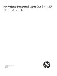
System board architecture<br />
The following figure shows the <strong>HP</strong> <strong>xw4600</strong> <strong>Workstation</strong> system board block diagram.<br />
Figure 1-1 System board block diagram<br />
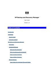
<strong>Workstation</strong> components<br />
The following figure shows the components of a typical <strong>HP</strong> <strong>xw4600</strong> <strong>Workstation</strong>. Drive configurations<br />
can vary.<br />
2 Chapter 1 Product overview ENWW
See http://partsurfer.hp.com for current information on supported spare parts.<br />
Figure 1-2 <strong>Workstation</strong> components view<br />
Table 1-1 Component view<br />
Item Description Item Description<br />
1 Power supply 9 Processor<br />
2 Hard drive 10 Memory module<br />
3 Optical drive 11 System board<br />
4 Side access panel 12 PCI Express card<br />
5 System fan 13 PCI card<br />
6 Chassis 14 Speaker<br />
7 Diskette drive 15 Front bezel<br />
8 Processor heatsink<br />
ENWW Product features 3
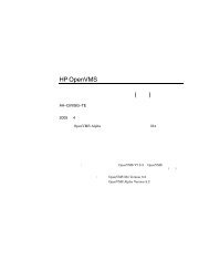
Front panel components<br />
The following figure shows the front panel components of a typical <strong>HP</strong> <strong>xw4600</strong> <strong>Workstation</strong>. Drive<br />
configurations can vary.<br />
Figure 1-3 Front panel components<br />
Table 1-2 Front panel components<br />
Item Symbol Description Item Symbol Description<br />
1 Optical drive eject button 8 IEEE-1394 Connector (optional)<br />
2 Power on light 9 Diskette drive eject button<br />
3 Power button 10 Diskette drive activity light<br />
4 Hard drive activity light 11 Diskette drive (optional)<br />
5 USB 2.0 (2) 12 5.25–inch drive bays (2)<br />
6 Headphone connector 13 Optical drive activity light<br />
7 Microphone connector 14 Optical drive<br />
4 Chapter 1 Product overview ENWW
Rear panel components<br />
The following figure shows the rear panel components of a typical <strong>HP</strong> <strong>xw4600</strong> <strong>Workstation</strong>.<br />
Figure 1-4 Rear panel components<br />
Table 1-3 Rear panel components<br />
Item Symbol Description Item Symbol Description<br />
1 Power supply Built-In Self Test (BIST)<br />
LED<br />
10 Padlock loop<br />
2 Universal chassis clamp opening 11 Graphics adapter<br />
3 PS/2 mouse connector (green) 12 eSATA adapter<br />
4 Parallel connector (red) 13 USB 2.0 (1)<br />
5 USB 2.0 (4) 14 USB 2.0 (2)<br />
6 Audio line-in connector (blue) 15 Microphone connector (pink)<br />
7 Audio line-out connector (green) 16 Serial connector (blue-green)<br />
8 RJ-45 network connector 17 PS/2 keyboard connector<br />
9 Cable lock slot 18 Power cord connector<br />
NOTE: The rear panel connectors are labeled with industry-standard icons and colors to assist you in<br />
connecting your peripheral devices.<br />
ENWW Product features 5
Serial number and COA label location<br />
Each workstation has two unique serial number labels (1) and a Certificate of Authentication (COA) label<br />
(2) (for Microsoft® Windows® preinstalled systems only). The serial number labels can usually be found<br />
on the top panel or on the side or rear of the workstation. Keep this number available when contacting<br />
customer service for assistance.<br />
Figure 1-5 Location of serial number and COA label<br />
Maximizing the airflow<br />
● Keep your workstation in an area where the airflow is not obstructed.<br />
● Keep the workstation off of surfaces where dust can gather.<br />
● Keep the front of the workstation clear of any obstruction.<br />
● Remove any dust on the front panel (vent area) and the rear fans with a small vacuum, compressed<br />
air, or dust rag.<br />
● Keep the back of the workstation at least 0.15 m (6 in.) away from a wall or other obstruction.<br />
Figure 1-6 Maintain proper clearance<br />
6 Chapter 1 Product overview ENWW
<strong>Workstation</strong> specifications<br />
The following table lists the physical characteristics of the <strong>HP</strong> <strong>xw4600</strong> <strong>Workstation</strong>.<br />
Table 1-4 Physical characteristics<br />
Weight (typical<br />
configuration)<br />
16 kg (35 lb.)<br />
Tower dimensions 45 cm (17.7 in.) high<br />
80 Plus power supply<br />
16.8 cm (6.6 in.) wide<br />
45.6 cm (17.9 in.) deep<br />
The <strong>HP</strong> <strong>xw4600</strong> <strong>Workstation</strong> includes a 475W energy efficient 80 Plus® power supply compatible with<br />
Energy Star requirements. This section describes the power supply and lists its specifications.<br />
Table 1-5 Power supply source voltages<br />
Source voltage Description<br />
+3.3V PCI, PCI Express, audio, CK505, ICH9R, super I/O, BIOS ROM, and<br />
onboard logic<br />
+5.1V Storage (hard drive, optical drive, diskette drive), PCI, PCI Express, ICH9R,<br />
audio, keyboard/mouse<br />
+12 V–B PCI, PCI Express, and system fans<br />
+12 V-D Storage (hard drive, optical drive, diskette drive), PCI Express x16 auxiliary<br />
connector<br />
+12 VCPU Input to onboard regulator that supplies power to the processor.<br />
-12V PCI, serial ports<br />
+5 VSB Sleep circuitry<br />
Table 1-6 Maximum current per rail<br />
Voltage rail Maximum continuous current<br />
+3.3V 15A<br />
+5.1V 21A<br />
+12 VCPU 15A<br />
+12 V-B 17.5A<br />
+12 V-D 12A<br />
-12V 0.3A<br />
+5 VSB 2.25A<br />
ENWW <strong>Workstation</strong> specifications 7
WARNING! Do not exceed 110W of 5-V and 3.3-V power combination.<br />
Do not exceed 34.5A (414W) of 12V (CPU/B/D) power combination.<br />
Do not exceed 475W of total continuous output power.<br />
Power supply specifications<br />
Table 1-7 Power supply specifications<br />
Item Description<br />
Power supply 475 watt custom power supply – (Wide<br />
Ranging, Active PFC)<br />
Operating voltage range 90 – 269 VAC<br />
Rated voltage range 100–240 VAC 118 VAC<br />
Rated line frequency 50–60 Hz 400 Hz<br />
Operating line frequency range 47–66 Hz 393–407 Hz<br />
Rated input current 10A @ 100-127 VAC<br />
Heat dissipation<br />
(Configuration and software dependent)<br />
6A @ 200–240 VAC<br />
10A @ 118 VAC<br />
Typical 1419 BTU/hr = (358 kg-cal/hr)<br />
Maximum 2027 BTU/hr = (511 kg-cal/hr)<br />
Power supply fan 92x25 mm variable speed<br />
ENERGY STAR 4.0 compliant Yes<br />
80 Plus compliant Yes<br />
FEMP Standby Power compliant @115V (
● One 160-GB SATA hard drive<br />
● One optical drive<br />
● One diskette drive<br />
● One monitor, powered separately<br />
Table 1-8 Power supply example configuration 1 energy consumption<br />
LAN<br />
Enabled<br />
115 VAC 230 VAC 100 VAC<br />
LAN<br />
Disabled<br />
LAN<br />
Enabled<br />
LAN<br />
Disabled<br />
LAN<br />
Enabled<br />
Windows Idle (S0) 67.4W 66.4W 65.5W<br />
Windows Busy Typ (S0) 89.7W 88.4W 88.2W<br />
Windows Busy Max (S0) 114.1W 109.6W 110.0W<br />
Sleep (S3)* 3.61W 2.82W 3.89W 3.12W 3.61W 2.82W<br />
Power Off (S5) 1.51W 1.30W 1.81W 1.60W 1,50W 1.28W<br />
* ENERGY STAR low energy mode.<br />
Table 1-9 Power supply example configuration 1 heat dissipation**<br />
LAN<br />
Enabled<br />
115 VAC 230 VAC 100 VAC<br />
LAN<br />
Disabled<br />
LAN<br />
Enabled<br />
LAN<br />
Disabled<br />
LAN<br />
Enabled<br />
Windows Idle (S0) 230.1 BTU/hr 226.6 BTU/hr 223.6 BTU/hr<br />
Windows Busy Typ (S0) 306.3 BTU/hr 301.6 BTU/hr 300.9 BTU/hr<br />
Windows Busy Max (S0) 389.4 BTU/hr 374.1 BTU/hr 375.4 BTU/hr<br />
LAN<br />
Disabled<br />
LAN<br />
Disabled<br />
Sleep (S3)* 12.3 BTU/hr 9.62 BTU/hr 13.3 BTU/hr 10.6BTU/hr 12.3 BTU/hr 9.62 BTU/hr<br />
Power Off (S5) 5.15 BTU/hr 4.44 BTU/hr 6.18 BTU/hr 5.46 BTU/hr 5.12 BTU/hr 4.37 BTU/hr<br />
* ENERGY STAR low energy mode.<br />
** Heat dissipation is calculated based on the measured watts, assuming the service level is attained for one hour.<br />
NOTE: To reach zero power consumption, unplug the workstation from the power outlet or use a power<br />
strip with a switch. For additional information on power-saving features, see your operating system<br />
documentation.<br />
Power supply example configuration 2<br />
● One 3.0 -GHz Intel® Core 2 Extreme QX6850 processor<br />
● Two 1-GB 800-MHz memory modules<br />
● Nvidia FX1700 graphics card<br />
● Two 73-GB SAS hard drives<br />
ENWW <strong>Workstation</strong> specifications 9
● 2 optical drives<br />
● 1 diskette drive<br />
Table 1-10 Power supply example configuration 2 energy consumption<br />
LAN<br />
Enabled<br />
115 VAC 230 VAC 100 VAC<br />
LAN<br />
Disabled<br />
LAN<br />
Enabled<br />
LAN<br />
Disabled<br />
LAN<br />
Enabled<br />
Windows Idle (S0) 113W 108W 113W<br />
WindowsBusy Typ (S0) 138W 133W 138W<br />
Windows Busy Max (S0) 186W 178W 183W<br />
Sleep (S3)* 3.70W 2.90W 3.95W 3.20W 3.70W 2.90W<br />
Power Off (S5) 1.52W 1.30W 1.81W 1.58W 1.50W 1.28W<br />
* ENERGY STAR low energy mode.<br />
Table 1-11 Power supply example configuration 2 heat dissipation**<br />
LAN<br />
Enabled<br />
115 VAC 230 VAC 100 VAC<br />
LAN<br />
Disabled<br />
LAN<br />
Enabled<br />
LAN<br />
Disabled<br />
LAN<br />
Enabled<br />
Windows Idle (S0) 386 BTU/hr 369 BTU/hr 386 BTU/hr<br />
Windows Busy Typ (S0) 471 BTU/hr 454 BTU/hr 471 BTU/hr<br />
Windows Busy Max (S0) 635 BTU/hr 608 BTU/hr 625 BTU/hr<br />
LAN<br />
Disabled<br />
LAN<br />
Disabled<br />
Sleep (S3)* 12.6 BTU/hr 9.89 BTU/hr 13.5 BTU/hr 10.9 BTU/hr 12.6 BTU/hr 9.89 BTU/hr<br />
Power off (S5) 5.19 BTU/hr 4.44 BTU/hr 6.18 BTU/hr 5.39 BTU/hr 5.12 BTU/hr 4.37 BTU/hr<br />
* ENERGY STAR low energy mode<br />
** Heat dissipation is calculated based on the measured watts, assuming the service level is attained for one hour.<br />
Power supply example configuration 3<br />
● One 3.0-GHz Intel® Pentium Dual Core E6850 processor<br />
● Two 1-GB 667-MHz memory modules<br />
● Nvidia FX1700 graphics card<br />
● Two 160-GB SATA hard drives<br />
● 1 optical drives<br />
Table 1-12 Power supply Example configuration 3 energy consumption<br />
115 VAC 230 VAC 100 VAC<br />
On-idle, ENERGY STAR 76.3W 75.3W 76.6W<br />
10 Chapter 1 Product overview ENWW
Idle (S0)<br />
ENERGY STAR Ptec (Total energy<br />
consumption)<br />
Windows running Linpack and<br />
Viewperf<br />
ENERGY STAR<br />
Sleep (S3)*<br />
ENERGY STAR<br />
Standby (Off) (S5)<br />
i1 * ENERGY STAR low energy mode<br />
115 VAC 230 VAC 100 VAC<br />
162.3W 159.6W 163.2W<br />
3.7W 4.1W 3.8W<br />
1.5W 1.8W 1.5W<br />
Table 1-13 Power supply example configuration 3 heat dissipation**<br />
On-idle, ENERGY STAR<br />
Idle (S0)<br />
ENERGY STAR Ptec (Total energy<br />
consumption)<br />
Windows running Linpack and<br />
Viewperf<br />
ENERGY STAR<br />
Sleep (S3)*<br />
System fans<br />
Table 1-12 Power supply Example configuration 3 energy consumption (continued)<br />
ENERGY STAR<br />
Standby (Off) (S5)<br />
115 VAC 230 VAC 100 VAC<br />
260 BTU/hr 257 BTU/hr 261 BTU/hr<br />
554 BTU/hr 545 BTU/hr 557 BTU/hr<br />
12.6 BTU/hr 14.0 BTU/hr 13.0 BTU/hr<br />
5.12 BTU/hr 6.14 BTU/hr 5.12 BTU/hr<br />
* ENERGY STAR low energy mode<br />
** Heat dissipation is calculated based on the measured watts, and assumes that the service level is attained for one hour.<br />
This workstation includes one rear system fan, one processor heatsink fan, and one power supply fan.<br />
In addition, an optional front system fan is available for special environments, and some graphics cards<br />
include onboard fans.<br />
ENWW <strong>Workstation</strong> specifications 11
Resetting the power supply<br />
If an overload triggers the power supply overload protection, all power is immediately disconnected. To<br />
reset the power supply:<br />
1. Disconnect the power cord from the workstation..<br />
2. Determine what caused the overload and fix the problem. See System diagnostics and<br />
troubleshooting on page 109 for troubleshooting information.<br />
3. Reconnect the power cord and reboot the workstation.<br />
When you power off the workstation through the operating system, power consumption falls below what<br />
is considered low power consumption, but does not reach zero. This low power consumption feature<br />
extends the life of the power supply.<br />
Environmental specifications<br />
This section describes the environmental specifications of your workstation.<br />
Table 1-14 Environmental specifications<br />
Temperature (operating) 5° to 35°C (40° to 95°F)<br />
Temperature (nonoperating) -40° to 60°C (-40° to 140°F)<br />
Humidity (operating) 8% to 85% RH, noncondensing<br />
Humidity (nonoperating) 8% to 90% RH, noncondensing<br />
Altitude (operating) 0 to 3,048m (10,000 ft)<br />
Altitude (nonoperating) 0 to 9,144m (30,000 ft)<br />
Shock (operating) 1/2-sine: 40G, 2–3 ms<br />
Shock (nonoperating) 1/2-sine: 160 cm/s, 2–3 ms (~100g)<br />
Square: 20G, 422 cm/s<br />
NOTE: Values represent individual shock events and are not<br />
indicative of repetitive shock events.<br />
Vibration (operating) Operating random: 0.5G (rms), 5–300 Hz<br />
Vibration (nonoperating) Random: 2.0G (rms), 10–500 Hz<br />
NOTE: Values are not indicative of continuous vibration.<br />
12 Chapter 1 Product overview ENWW
ENERGY STAR<br />
<strong>HP</strong> computers marked with the ENERGY STAR logo are compliant with the applicable U.S.<br />
Environmental Protection Agency (EPA) ENERGY STAR specifications for computers. The EPA<br />
ENERGY STAR logo does not imply endorsement by the EPA. As an ENERGY STAR Partner, <strong>Hewlett</strong>-<br />
<strong>Packard</strong> Company has determined the products marked with the ENERGY STAR logo are ENERGY<br />
STAR qualified per the applicable ENERGY STAR guidelines for energy efficiency. The following logo<br />
appears on all ENERGY STAR qualified computers.<br />
Figure 1-7 ENERGY STAR logo<br />
The ENERGY STAR Computers Program was created by the EPA to promote energy efficiency and<br />
reduce air pollution through more energy-efficient equipment in homes, offices, and factories. One way<br />
products achieve this energy efficiency is by reducing power consumption when not being used through<br />
the Microsoft Windows Power Management feature.<br />
The Power Management feature enables the workstation to enter a low-power (or “sleep”) mode after<br />
a period of inactivity. When used with an external monitor that is ENERGY STAR compliant, this feature<br />
also supports the monitor's similar power management features.<br />
To take advantage of this energy savings:<br />
● The Power Management feature has been preset to power down the computer after 30 minutes of<br />
inactivity.<br />
● The Power Management feature has been preset to power down the monitor after 15 minutes of<br />
inactivity.<br />
Both the computer and monitor can be woken from “sleep” mode through user interaction with any of<br />
the computer input devices (mouse, keyboard, and so on). When configured with Wake On LAN (WOL)<br />
enabled, the workstation can also be awoken by a network signal.<br />
See the EPA ENERGY STAR Power Management Web site for more information about the energy and<br />
financial savings potential of the Power Management Feature: http://www.energystar.gov/<br />
powermanagement.<br />
See the EPA ENERGY STAR Web site for more information about the ENERGY STAR program and<br />
its environmental benefits: http://www.energystar.gov.<br />
CAUTION: Using the Energy Save Monitor feature with monitors that are not ENERGY STAR<br />
compliant can cause video distortion when an Energy Save timeout occurs.<br />
NOTE: ENERGY STAR is not supported on Linux workstations.<br />
If it is necessary to restore the operating system, you must also reset the ENERGY STAR settings (if<br />
applicable) after the restore.<br />
To verify the factory default power settings for your workstation, select Start>Control Panel and doubleclick<br />
Power Options.<br />
ENWW ENERGY STAR 13
Dual- and quad-core processors<br />
The <strong>HP</strong> <strong>xw4600</strong> <strong>Workstation</strong> supports dual- and quad-core processors that provide two or four true<br />
processors in a single socket. Dual- and quad-core processors are better at handling the load of multithreaded<br />
applications (such as rendering images in Digital Content Creation) and highly multi-tasked<br />
environments (such as running several productivity applications while listening to music).<br />
<strong>HP</strong> Cool Tools<br />
<strong>HP</strong> <strong>xw4600</strong> <strong>Workstation</strong> includes additional software preloaded that is not automatically installed when<br />
you first boot your system. Additionally, there are a number of preinstalled tools on your workstation that<br />
can enhance your workstation experience. To access or learn more about these applications:<br />
● Open the <strong>HP</strong> Cool Tools folder by selecting Start>All Programs><strong>HP</strong> Cool Tools.<br />
● Select the <strong>HP</strong> Cool Tools icon on the desktop.<br />
To learn more about these applications, select <strong>HP</strong> Cool Tools—Learn More.<br />
To install or launch the applications, select the appropriate application.<br />
14 Chapter 1 Product overview ENWW
2 Configuring and restoring the operating<br />
system<br />
This chapter describes how to install and restore the operating system and includes the following topics.<br />
● Setting up Microsoft Windows Vista Business software on page 15<br />
● Setting up Microsoft Windows XP Professional on page 18<br />
● Protecting your software on page 22<br />
● <strong>HP</strong> software on page 22<br />
● Setting up Red Hat Linux on page 23<br />
If your workstation includes a preinstalled operating system, it is configured automatically the first time<br />
you power on the workstation.<br />
CAUTION: Do not add optional hardware or third-party devices to the <strong>HP</strong> workstation until the<br />
operating system is successfully installed. Adding hardware might cause errors and prevent the<br />
operating system from installing correctly.<br />
Setting up Microsoft Windows Vista Business software<br />
This section describes how to install and restore Microsoft Windows Vista® Business on your<br />
workstation.<br />
Configuring the Windows Vista Business operating system<br />
This section describes how to configure the Windows Vista Business operating system on your <strong>HP</strong><br />
workstation.<br />
Configuring the software<br />
When you first power on the workstation, the operating system is configured. Configuration takes<br />
approximately 5 to 10 minutes. Carefully follow the instructions on the screen to complete the<br />
configuration.<br />
CAUTION: After the automatic configuration has begun, do not power off your workstation until this<br />
process is complete. Powering off your workstation during the process might damage the software that<br />
runs the system.<br />
If it is necessary to reinstall the operating system, see the operating system documentation included<br />
with your workstation. Additional information is available from the online help tool after you have<br />
successfully configured the operating system.<br />
ENWW Setting up Microsoft Windows Vista Business software 15
Selecting a language<br />
When the preinstalled operating system is first booted, you might be prompted to select a language for<br />
the operating system. After selecting the language, read and follow the instructions on the screen<br />
to complete the installation of the operating system. This process might take a while, depending on the<br />
system hardware configuration and the language choice. During the process, do not power off your<br />
workstation unless you are prompted to do so.<br />
After you have selected a language during the initial boot of the operating system, the language is locked<br />
on the hard drive. If the system is restored using <strong>HP</strong> Backup and Recovery, only the previously selected<br />
language can be installed. If using RestorePlus! DVDs, the RestorePlus! DVD looks for the language<br />
stored on the hard drive and restores only the original preinstalled language. If a new hard drive is<br />
installed or no language is found on the disk, the RestorePlus! DVD installs any language requested.<br />
Creating recovery disks<br />
For more information about the <strong>HP</strong> Backup and Recovery, see Restoring the Windows Vista Business<br />
operating system on page 16.<br />
Installing or upgrading device drivers<br />
To install hardware devices after the operating system installation is complete, the appropriate device<br />
drivers must be installed before the devices are installed. In addition, for optimum performance, your<br />
operating system must have the most recent updates, patches, and software fixes. For driver and<br />
software updates, access the following resources:<br />
● The Microsoft Web site provides updates for your operating system, including current patches and<br />
software fixes.<br />
● Device drivers are provided on CDs supplied with peripheral devices.<br />
● Some peripheral device drivers developed for Windows XP or Vista might not be included with your<br />
workstation. Current device drivers are available at http://www.hp.com/support/<br />
workstation_swdrivers.<br />
● Driver installation and workstation operation documentation is available at http://www.hp.com/<br />
support/workstation_manuals/.<br />
Restoring the Windows Vista Business operating system<br />
There are several methods to restore the Windows Vista Business operating system on your workstation<br />
to a near-factory state, or to the state of the system at a predefined restore point. Your workstation has<br />
a recovery partition on the system hard drive that contains the software and data required for the restore<br />
process as described in the following sections.<br />
If you must restore the operating system with Windows Vista Business Original Equipment Manufacturer<br />
(OEM) DVDs (that is, installing without using the Restore Plus! DVDs), you must call Microsoft and<br />
provide your Stock Keeping Unit (SKU) number. The SKU information is listed on the service tag. It<br />
appears as the OS product number in the lower right hand portion of the tag in this format: “OS:<br />
XXXXXXX,” where “XXXXXXX” is the OS product number.<br />
Using the <strong>HP</strong> Backup and Restore process<br />
The Windows operating system and device drivers (for devices included with the system) are reinstalled<br />
using the <strong>HP</strong> Backup and Restore (<strong>HP</strong>BR) process. This process can be executed from a DVD, CD, or<br />
from the recovery partition on your system hard drive.<br />
16 Chapter 2 Configuring and restoring the operating system ENWW
To launch the <strong>HP</strong>BR, slect Start>All Programs><strong>HP</strong> Backup & Recovery><strong>HP</strong> Backup and Recovery<br />
Manager.<br />
CAUTION: Before you attempt any operating system restore, backup your data . All data on the<br />
Windows partition is deleted when you perform a system restore using the <strong>HP</strong>BR process. However,<br />
the recovery partition on the system drive and other partitions will not be affected.<br />
Creating system recovery DVDs or CDs<br />
You can create a set of system recovery DVDs or CDs if you have a writable optical drive. After launching<br />
the <strong>HP</strong> Backup and Restore Manager, you can create International Standards Organization (ISO)<br />
images of the factory image, or write them directly to CD or DVD. You can also create a supplemental<br />
<strong>HP</strong> Backup and Recovery Manager CD. (There may be additional CDs you can create depending on<br />
the options purchased.) You can also move CD images to another location, such as a network share,<br />
or to be copied to a DVD or CD at a later time or from another system.<br />
Restoring from <strong>HP</strong>BR DVDs or CDs<br />
To start the system recovery process, boot from the DVD or CD you created previously, then carefully<br />
follow the online instructions.<br />
Restoring a system directly from the recovery partition<br />
Follow these steps to start the <strong>HP</strong>BR system restore process from the Recovery Manager:<br />
1. Boot the workstation.<br />
2. When prompted on the boot splash screen to enter the Recovery Manager, press F11.<br />
3. Follow the prompts to restore the system to factory-like condition.<br />
Reclaiming hard drive space from the recovery partition<br />
To free up hard drive space, you can remove only the recovery partition, or you can completely uninstall<br />
the <strong>HP</strong> Backup and Recovery Manager application.<br />
CAUTION: If the recovery partition is removed:<br />
– The F11 Emergency Recovery function becomes unavailable.<br />
– The ability to recover the system is lost.<br />
– Any recovery images contained in the recovery partition are deleted.<br />
– The ability to create a recovery media set is lost.<br />
CAUTION: If you uninstall the <strong>HP</strong> Backup and Recovery Manager application, emergency recovery<br />
and data backup and recovery are no longer possible.<br />
● Removing only the recovery partition—The recovery partition can be removed by selecting<br />
Remove <strong>HP</strong> Recovery Partition from the <strong>HP</strong> Backup and Recovery program folder. When the<br />
<strong>HP</strong> Recovery Partition is removed, the recovery partition is deleted, the user partition is extended<br />
to reclaim the unused hard drive space, and the F11 boot prompt is removed. The <strong>HP</strong> Backup and<br />
Recovery Manager application remains and can be used for data backup and restore.<br />
● Uninstalling the <strong>HP</strong> Backup and Recovery Manager application—The <strong>HP</strong> Backup and<br />
Recovery Manager application can be uninstalled using the Programs and Features utility under<br />
ENWW Setting up Microsoft Windows Vista Business software 17
Windows Control Panel>Programs and Features. When the application is uninstalled, the<br />
recovery partition is deleted, the user partition is extended to reclaim the unused space, and the<br />
F11 boot prompt is removed. After the application is uninstalled, emergency recovery and data<br />
backup and recovery can no longer be performed.<br />
CAUTION: Deleting the recovery partition or uninstalling the <strong>HP</strong> Backup and Recovery Manager<br />
application reduces or eliminates the ability to recover the system.<br />
Ordering backup software<br />
If you are unable to create system recovery CDs or DVDs, you can order a recovery disk set from the<br />
<strong>HP</strong> support center. Before calling <strong>HP</strong> to order the software, have your workstation serial number<br />
available.<br />
To obtain the support center telephone number for your region:<br />
1. Go to http://welcome.hp.com/country/us/en/wwcontact_us.html.<br />
2. Select your region.<br />
3. Under the Call <strong>HP</strong> heading, select Technical support after you buy.<br />
Transferring files and settings using Windows Easy Transfer<br />
Windows Easy Transfer, a Microsoft data migration tool, provides a guide that helps you choose what<br />
files and data to transfer from another Windows computer to your Windows Vista Business workstation<br />
and explains how to transfer it. You can use one of the following interconnect or storage methods with<br />
Windows Easy Transfer to migrate data from another Windows computer to your workstation:<br />
● Network—can be used when both the source computer and your workstation are connected to the<br />
same network.<br />
● Easy Transfer cable—a specially designed USB cable that connects the source computer to your<br />
workstation when performing a Windows Easy Transfer. While an Easy Transfer cable is not a<br />
standard USB cable, it is commonly available from local electronics suppliers.<br />
● DVDs or CDs—can be used if you have writeable DVD or CD drives on the source computer and<br />
your workstation.<br />
● USB flash drive or an external hard drive—can access both the source computer and your<br />
workstation.<br />
To use the Windows Easy Transfer tool, select Start>All Programs>Accessories>System<br />
Tools>Windows Easy Transfer.<br />
NOTE: For more information about using Windows Easy Transfer with your workstation, see<br />
http://www.microsoft.com/windows/products/windowsvista/features/details/easytransfer.mspx.<br />
Setting up Microsoft Windows XP Professional<br />
This section describes how to configure and restore Microsoft® Windows XP Professional on your<br />
workstation.<br />
18 Chapter 2 Configuring and restoring the operating system ENWW
Configuring Windows XP Professional<br />
This section describes how to configure Windows XP on your workstation.<br />
When you first power on to the workstation, the operating system is configured. Configuration takes<br />
approximately 5 to 10 minutes. Carefully follow the instructions on the screen to complete the<br />
configuration.<br />
CAUTION: After configuration begins, do not power off your workstation until the process is complete.<br />
Powering off your workstation during the configuration process might damage the software that runs the<br />
system.<br />
If it is necessary to reinstall the operating system, see the operating system documentation included<br />
with your workstation. Additional information is available from the online help tool after you have<br />
successfully configured the operating system.<br />
Selecting a language<br />
When the preinstalled operating system is first booted, you might be prompted to select a language for<br />
the operating system. After selecting the language, read and follow the instructions on the screen<br />
to complete the installation of the operating system. This process might take quite a while, depending<br />
on the system hardware configuration and the language choice. During the process, do not power off<br />
your workstation unless you are prompted to do so.<br />
NOTE: After you have selected a language during the initial boot of the operating system, the language<br />
is locked on the hard drive. If the system is restored using <strong>HP</strong> Backup and Recovery, only the previously<br />
selected language can be installed. If using RestorePlus! DVDs, the RestorePlus! DVD looks for the<br />
language stored on the hard drive and restores only the original preinstalled language. If a new hard<br />
drive is installed, or no language is found on the disk, the RestorePlus! DVD installs any language<br />
requested.<br />
Creating recovery disks<br />
Refer to or Restoring the Windows XP Professional operating system on page 20 for details on the<br />
<strong>HP</strong> Backup and Recovery process.<br />
Installing or upgrading device drivers<br />
To install hardware devices after the operating system installation is complete, the appropriate device<br />
drivers must be installed before the devices are installed. In addition, for optimum performance, your<br />
operating system must have the most recent updates, patches, and software fixes. For driver and<br />
software updates, access the following resources:<br />
● The Microsoft Web site provides updates for your operating system, including current patches and<br />
software fixes.<br />
● Device drivers are provided on CD supplied with peripheral devices.<br />
● Some peripheral device drivers developed for Windows XP or Vista might not be included with your<br />
workstation. Current device drivers are available at: http://www.hp.com/support/.<br />
● For documentation on installing drivers and workstation operation, see http://www.hp.com/support/<br />
workstation_manuals/.<br />
ENWW Setting up Microsoft Windows XP Professional 19
Restoring the Windows XP Professional operating system<br />
There are several methods to restore the Windows XP operating system on your workstation to a nearfactory<br />
state, or to the state of the system at a predefined snapshot in time. Your workstation has a<br />
recovery partition on the system hard drive that contains the software and data required for the restore<br />
process as described in the following sections.<br />
The RestorePlus! process<br />
The Windows operating system and device drivers (for devices included with the system) are reinstalled<br />
using the RestorePlus! process. Some application software might not be restored using this process. If<br />
specific application software was not restored, you must install the application software from the<br />
appropriate application CD. The RestorePlus! process can be executed from a CD or from the recovery<br />
partition on your system hard drive.<br />
CAUTION: Before you attempt any operating system restore, back up your data . All data on the<br />
Windows partition is deleted when you perform a system restore using the RestorePlus! process.<br />
However, the recovery partition on the system drive and other partitions are not affected.<br />
Creating a RestorePlus! CD<br />
You can create a set of the system recovery CDs if you have a writable optical drive. When you first<br />
boot the workstation, you are prompted to create CDs for RestorePlus!, the Windows operating system,<br />
and a supplemental <strong>HP</strong> Backup and Recovery Manager. (There might be additional CDs you can create,<br />
depending on the options purchased.) You also have the option to move CD images to another location,<br />
such as a network share, to be copied to CD at a later time, or from another system.<br />
Restoring your system from RestorePlus! CDs<br />
Start the RestorePlus! process by booting from the RestorePlus! CD.<br />
Restoring your system from RestorePlus! on the recovery partition<br />
Follow these steps to start the RestorePlus! process from the Emergency Recovery menu:<br />
1. Boot the workstation.<br />
2. When prompted during the boot process to select the Emergency Recovery menu, press F11 . The<br />
F11 prompt appears briefly during the boot process.<br />
If you have a recovery partition but the F11 prompt is not visible:<br />
a. To access the setup menu, press F10. (See Using the Computer Setup (F10) Utility<br />
on page 28 for details.)<br />
b. From the drop down menu, select Advanced.<br />
c. Select Power-On Options.<br />
d. Ensure that the F11 prompt is set to Displayed.<br />
e. Ensure that Factory Recovery Boot Support is set to Enabled.<br />
f. Reboot the workstation and press F11 when prompted.<br />
3. Select Recover PC’s factory installed operating system, drivers, utilities, and applications<br />
from the Emergency Recovery menu.<br />
20 Chapter 2 Configuring and restoring the operating system ENWW
NOTE: Some applications might not be restored using this method.<br />
Reclaiming hard drive space from the recovery partition<br />
The recovery partition can be removed to reclaim the hard drive space.<br />
CAUTION: If the recovery partition is removed:<br />
- The F11 Emergency Recovery function becomes unavailable.<br />
- The ability to recover the system from data on the recovery partition is lost.<br />
- Any recovery images contained in the recovery partition are deleted.<br />
- The ability to create a recovery media set is lost.<br />
To free up hard drive space, you can remove only the recovery partition, or you can completely uninstall<br />
the <strong>HP</strong> Backup and Recovery Manager application.<br />
CAUTION: If you uninstall the <strong>HP</strong> Backup and Recovery Manager application, Emergency Recovery<br />
and data backup and recovery can no longer be performed.<br />
● Removing only the recovery partition—The recovery partition can be removed by selecting<br />
Remove <strong>HP</strong> Recovery Partition from from the <strong>HP</strong> Backup and Recovery program folder. When<br />
the <strong>HP</strong> Recovery Partition is removed, the recovery partition is deleted, the user partition is<br />
extended to reclaim the unused hard drive space, and the F11 boot prompt is removed. The <strong>HP</strong><br />
Backup and Recovery Manager application remains, and can be used for data backup and restore.<br />
● Uninstalling the <strong>HP</strong> Backup and Recovery Manager application—The <strong>HP</strong> Backup and<br />
Recovery Manager application can be uninstalled using the Programs and Features utility under<br />
Windows Control Panel>Programs and Features. When the application is uninstalled, the<br />
recovery partition is deleted, the user partition is extended to reclaim the unused space, and the<br />
F11 boot prompt is removed. After the application is uninstalled, emergency recovery as well as<br />
data backup and recovery can no longer be performed.<br />
CAUTION: Deleting the recovery partition or uninstalling the <strong>HP</strong> Backup and Recovery Manager<br />
application reduces or eliminates the ability to recover the system.<br />
Using the <strong>HP</strong> Backup and Restore process<br />
The Windows operating system and device drivers (for devices included with the system) are reinstalled<br />
using the <strong>HP</strong> Backup and Restore (<strong>HP</strong>BR) process. This process can be executed from a DVD, CD, or<br />
from the recovery partition on your system hard drive.<br />
To launch the <strong>HP</strong>BR, slect Start>All Programs><strong>HP</strong> Backup & Recovery><strong>HP</strong> Backup and Recovery<br />
Manager.<br />
CAUTION: Before you attempt any operating system restore, backup your data . All data on the<br />
Windows partition is deleted when you perform a system restore using the <strong>HP</strong>BR process. However,<br />
the recovery partition on the system drive and other partitions will not be affected.<br />
Creating system recovery DVDs or CDs<br />
You can create a set of system recovery DVDs or CDs if you have a writable optical drive. After launching<br />
the <strong>HP</strong> Backup and Restore Manager, you can create International Standards Organization (ISO)<br />
images of the factory image, or write them directly to CD or DVD. You can also create a supplemental<br />
<strong>HP</strong> Backup and Recovery Manager CD. (There may be additional CDs you can create depending on<br />
ENWW Setting up Microsoft Windows XP Professional 21
the options purchased.) You can also move CD images to another location, such as a network share,<br />
or to be copied to a DVD or CD at a later time or from another system.<br />
Restoring from <strong>HP</strong>BR DVDs or CDs<br />
To start the system recovery process, boot from the DVD or CD you created previously, then carefully<br />
follow the online instructions.<br />
Restoring a system directly from the recovery partition<br />
Follow these steps to start the <strong>HP</strong>BR system restore process from the Recovery Manager:<br />
1. Boot the workstation.<br />
2. When prompted on the boot splash screen to enter the Recovery Manager, press F11 .<br />
3. Follow the prompts to restore the system to factory-like condition.<br />
Ordering backup software<br />
If you are unable to create system recovery CDs or DVDs, you can order a recovery disk set from the<br />
<strong>HP</strong> support center.<br />
NOTE: Before calling <strong>HP</strong> to order the software, have your workstation serial number available.<br />
To obtain the support center telephone number for your region:<br />
1. Visit http://www.hp.com/support/contact<strong>HP</strong>.<br />
2. Select your region.<br />
3. Under the Call <strong>HP</strong> heading, select Technical support after you buy.<br />
Protecting your software<br />
To protect your software from loss or damage, keep a backup copy of all system software and related<br />
files stored on the hard drive. For instructions on making backup copies of data files, see the operating<br />
system or backup utility documentation.<br />
<strong>HP</strong> software<br />
The following <strong>HP</strong> software might be installed on your workstation, depending on the operating system<br />
and options purchased:<br />
● Computer Setup (F10) Utility and diagnostics<br />
● <strong>HP</strong> support software, including device drivers<br />
● Security management tools (optional)<br />
● Software support management tools<br />
Additional software is available for download:<br />
● <strong>HP</strong> Client Manager Software is available at http://www.hp.com/go/easydeploy<br />
● System Software Manager is available at http://www.hp.com/go/ssm<br />
22 Chapter 2 Configuring and restoring the operating system ENWW
NOTE: In certain situations, additional <strong>HP</strong> software might be required<br />
Setting up Red Hat Linux<br />
This section describes how to install and restore the Red Hat Linux operating system on your<br />
workstation.<br />
Linux preinstalled workstations<br />
With Linux preinstalled, follow the instructions in this section to set up your operating system and<br />
software.<br />
After the boot process is complete, you can view additional <strong>HP</strong> Linux documentation by opening your<br />
Web browser (the browser is automatically set to use the local <strong>HP</strong> documentation page as its default).<br />
You can also access Linux links for Red Hat (Internet access is required) by using your Web browser.<br />
For additional information about setting up Linux-preinstalled or Linux-enabled workstations, see the<br />
<strong>HP</strong> User Manual for Linux at: http://www.hp.com/support/linux_user_manual.<br />
For more information about <strong>HP</strong> and Linux, see http://www.hp.com/linux.<br />
Starting the Linux operating system<br />
The first time you boot your workstation, the Red Hat First Boot utility displays. This program enables<br />
you to enter your password, network, graphics, time, and keyboard settings for your workstation.<br />
CAUTION: After the automatic installation has begun, do not power down your workstation until the<br />
process is complete. Powering down your workstation during the installation process might damage the<br />
software that runs your workstation or prevent its proper installation.<br />
When you enable the YPBind feature in the Network tab of the Linux Setup Tool, you might get a blank<br />
screen for approximately 15–30 seconds after you have selected and saved all of your settings and<br />
exited the utility. This behavior is expected. The boot process continues its execution after the screen<br />
returns.<br />
Restoring the Linux operating system on preloaded workstations<br />
The <strong>HP</strong> Driver CD and Red Hat Enterprise Linux (RHEL) restore media are required to restore the Linux<br />
operating system. Download the most recent <strong>HP</strong> Driver CD to obtain new enhancements.<br />
NOTE: Linux does not support mixed drive types in a manufacturing preload. When restoring the<br />
operating system, mixed drive types can be handled with the restoration media.<br />
Creating restore media<br />
<strong>HP</strong> Red Hat Enterprise Linux includes a Red Hat ISO icon on the desktop. You can click on this icon to<br />
go to the /iso directory. The /iso directory contains all the iso images used to preload your workstation.<br />
To recover or restore the original image, follow the instructions in the readme file in the /iso directory to<br />
copy the ISO image file onto CDs<br />
NOTE: <strong>HP</strong> recommends that you copy the ISO recovery images to CD as backup files in case your<br />
workstation experiences a hard drive failure.<br />
The /iso directory also contains an ISO image of the <strong>HP</strong> Driver CD used to create your preloaded system.<br />
You can use this version or download the latest version from the <strong>HP</strong> Website.<br />
ENWW Setting up Red Hat Linux 23
Downloading the latest <strong>HP</strong> driver CD contents<br />
To download the latest <strong>HP</strong> Driver CD:<br />
1. Go to http://www.hp.com and select Software and Drive Downloads.<br />
2. Locate your workstation and operating system.<br />
3. Select your driver CD and then follow the directions under the Release Notes.<br />
Reinstalling the factory Linux image with the <strong>HP</strong> driver CD<br />
1. Boot your workstation from the Red Hat box set, Binary CD 1.<br />
2. When prompted, insert the Linux operating system restore media CDs.<br />
3. Continue following the installation prompts until the operating system is successfully installed.<br />
4. Configure the X server to start on reboot.<br />
5. Reboot your workstation.<br />
6. Follow the onscreen prompts to set up your system with the Red Hat First Boot utility.<br />
7. When prompted by First Boot to add additional CDs, insert the <strong>HP</strong> Driver CD into the optical drive<br />
of your workstation.<br />
8. Select Install next to Additional CDs. The <strong>HP</strong> Driver CD window opens.<br />
9. To begin the installation, select Press to continue.<br />
When installation is complete, you are given two options— Reboot now... (on the left side), and<br />
Press to continue, reboot later... (on the right side).<br />
10. Select Reboot now...<br />
Upgrading device drivers<br />
To upgrade a Linux device driver, see http://www.hp.com/support/workstation_swdrivers.<br />
Linux-enabled workstations<br />
Linux-enabled workstations do not have Linux preinstalled, nor do they include installation media for a<br />
Linux distribution. To install Linux, you must have the installation binary set for a Linux distribution (CD<br />
or DVD media, or a version on your network), and the <strong>HP</strong> Installer Kit for Linux. The <strong>HP</strong> Installer kit<br />
includes the <strong>HP</strong> CDs necessary to complete the installation of all versions of the distribution box set that<br />
are supported by <strong>HP</strong> workstation hardware. See the Linux hardware support matrix at<br />
http://www.hp.com/support/linux_hardware_matrix to determine which versions of are supported on<br />
your workstation.<br />
NOTE: If you want to use the drivers available in the <strong>HP</strong> Installer kit with Linux distributions other than<br />
RHEL, you must manually extract the drivers from the <strong>HP</strong> Driver CD and install them. <strong>HP</strong> does not test<br />
the installation of these drivers on other Linux distributions, nor does <strong>HP</strong> support this type of operation.<br />
24 Chapter 2 Configuring and restoring the operating system ENWW
Verifying hardware compatibility<br />
To determine which Linux versions are supported on your <strong>HP</strong> workstation hardware:<br />
1. See http://www.hp.com/support/linux_hardware_matrix.<br />
2. Select your <strong>HP</strong> workstation model.<br />
Setting up Red Flag Linux<br />
<strong>Hewlett</strong>-<strong>Packard</strong> offers the Red Flag Linux operating system as a preloaded option on the <strong>HP</strong> <strong>xw4600</strong><br />
<strong>Workstation</strong> in certain countries, but <strong>HP</strong> does not support the Red Flag Linux operating system. For<br />
more information about Red Flag Linux and the Red Flag operating system software, see<br />
http://www.redflag-linux.com.<br />
ENWW Setting up Red Hat Linux 25
26 Chapter 2 Configuring and restoring the operating system ENWW
3 System management<br />
This section describes the various tools and utilities that provide system management for your<br />
workstation and includes the following topics:<br />
● Computer Setup (F10) Utility on page 27<br />
● <strong>Workstation</strong> management on page 35<br />
Computer Setup (F10) Utility<br />
The Computer Setup (F10) Utility enables you to:<br />
● Change factory default settings and set or change the system configuration, which might be<br />
necessary when you add or remove hardware.<br />
● Determine if all of the devices installed on the workstation are recognized by the system and<br />
functioning properly.<br />
● Determine information about the operating environment of the workstation.<br />
● Solve system configuration errors that are detected but not automatically fixed during the Power-<br />
On Self-Test (POST).<br />
● Establish and manage passwords and other security features.<br />
● Establish and manage energy-saving time-outs (not supported on Linux platforms).<br />
● Modify or restore factory default settings.<br />
● Set the system date and time.<br />
● Set, view, change, or verify the system configuration, including settings for processor, graphics,<br />
memory, audio, storage, communications, and input devices.<br />
● Modify the boot order of installed mass storage devices such as SATA, SAS, diskette drives, optical<br />
drives, network drives, and LS-120 drives.<br />
● Configure the boot priority of SATA and SAS hard-drive controllers.<br />
● Enable or disable Network Server Mode, that enables the workstation to boot the operating system<br />
when the power-on password is enabled with or without a keyboard or mouse attached. When<br />
attached to the system, the keyboard and mouse remain locked until the power-on password is<br />
entered.<br />
● Select POST Messages Enabled or Disabled to change the display status of POST messages.<br />
POST Messages suppresses most POST messages, such as memory count, product name, and<br />
other non-error text messages. If a POST error occurs, the error is displayed regardless of the<br />
ENWW Computer Setup (F10) Utility 27
BIOS ROM<br />
mode selected. To manually switch to POST Messages Enabled during POST, press any key<br />
except F1 through F12.<br />
● Establish an Ownership Tag, the text of which is displayed each time the system is powered on or<br />
restarted.<br />
● Enter the Asset Tag or property identification number assigned by your company to this<br />
workstation.<br />
● Enable power-on password prompts during system restarts (warm-boots) and power on.<br />
● Hide or show the integrated I/O functionality, including serial, USB, or parallel ports, audio, or<br />
embedded NIC. Any hidden devices are inaccessible which increases overall system security.<br />
● Enable or disable removable media boot ability.<br />
● Enable or disable removable media write ability (if supported by hardware).<br />
● Replicate your system setup by saving system configuration information on CD or diskette and<br />
restoring it on one or more workstations.<br />
● Execute self-tests on specified SATA and SAS hard drives (if supported by the drive).<br />
The BIOS ROM is a collection of machine language programs stored as firmware in ROM. It includes<br />
functions such as POST, PCI device initialization, Plug and Play support, power management, and the<br />
Computer Setup (F10) Utility. The BIOS ROM is a 1-MB Serial Peripheral Interface (SPI) port. The<br />
firmware contained in the BIOS ROM supports the following systems and specifications:<br />
● Microsoft Windows Hardware Quality Labs (WHQL)<br />
● Alert-On-LAN (AOL) and Wake-On-LAN (WOL)<br />
● Advanced Configuration and Power Interface (ACPI) 1.0 and OnNow<br />
● System Management BIOS (SMBIOS) 2.3.5<br />
● PC98/99/00 and NetPC<br />
● Preboot Execution Environment (PXE) boot ROM for the integrated LAN controller<br />
● BIOS Boot Specification 1.01<br />
● Enhanced Disk Drive Specification 3.0<br />
● “El Torito” Bootable CD Format Specification 1.0<br />
● AT Attachment Packet Interface (ATAPI) Removable Media Device BIOS Specification 1.0<br />
● Multiprocessor Specification (MPS) 1.4 (for booting Linux SMP)<br />
Using the Computer Setup (F10) Utility<br />
You can only open the Computer Setup (F10) Utility by powering on or restarting the workstation.<br />
28 Chapter 3 System management ENWW
To access the Computer Setup (F10) Utility menu:<br />
1. Power on or restart the workstation.<br />
2. As soon as your display is active and F10=Setup appears in the lower right corner of the screen,<br />
press the F10 key .<br />
NOTE: If you do not press F10 at the appropriate time, try again. Turn the workstation off, then<br />
on, and press F10 again to access the utility. You can also press the Ctrl + Alt + Delete keys before<br />
boot if you miss the opportunity to press F10.<br />
3. Select your language from the list and press the Enter key. In the Computer Setup (F10) Utility<br />
menu, five headings are displayed: File, Storage, Security, Power, and Advanced.<br />
4. Use the left and right arrow keys to select the appropriate heading. Use the up and down arrow<br />
keys to select an option, and then press Enter.<br />
5. To apply and save changes, select File>Save Changes, and then select F10=YES.<br />
● If you have made changes that you do not want applied, select Ignore Changes and then<br />
select F10=YES.<br />
● To reset to factory settings, select File>Default setup>Restore Factory Settings as<br />
Default. Press F10 to accept the changes. Select Apply Defaults and Exit. This option<br />
restores the original factory system defaults.<br />
CAUTION: Do not power off the workstation while the ROM is saving your Computer Setup (F10)<br />
Utility changes because the Complementary Metal-Oxide Semiconductor (CMOS) could become<br />
corrupted. After you exit the F10 Setup screen, it is safe to disconnect power from the workstation.<br />
Computer Setup (F10) Utility menu<br />
NOTE: With new BIOS releases, the following content is subject to change , so your menu might<br />
appear different than shown.<br />
Table 3-1 Computer Setup (F10) Utility menu descriptions<br />
Heading Option Description<br />
File System<br />
Information<br />
● Product Name<br />
● SKU Number<br />
● Processor Type/Speed/Stepping<br />
● Cache Size (L1/L2)<br />
● Installed Memory Size<br />
● Integrated MAC<br />
● System BIOS<br />
● Chassis Serial Number<br />
● Asset Tracking Number<br />
About Displays copyright information.<br />
Set Time and<br />
Date<br />
Enables you to set system time and date.<br />
ENWW Computer Setup (F10) Utility 29
Table 3-1 Computer Setup (F10) Utility menu descriptions (continued)<br />
Heading Option Description<br />
Flash System<br />
ROM<br />
Replicated<br />
Setup<br />
CD-ROM—Enables you to upgrade the BIOS from a ROM image on a CD.<br />
USB—Enables you to upgrade the BIOS from a ROM image on a USB drive or memory stick.<br />
Save to Removable Media—Saves the system configuration, including CMOS, in the qsetup.txt<br />
file. This file can be saved to a formatted, blank 1.44-MB diskette, or to a USB device.<br />
Restore from Removable Media—Restores the system configuration from a diskette.<br />
Default Setup Save Current Settings as Default—Saves the current settings as default settings for the next<br />
operation.<br />
Apply Defaults<br />
and Exit<br />
Ignore Changes<br />
and Exit<br />
Save Changes<br />
and Exit<br />
Storage Device<br />
Configuration<br />
Restore Factory Settings as Default—Restores the factory settings as the default settings for the<br />
next operation.<br />
Restores factory default settings.<br />
Exits computer setup without applying or saving any changes.<br />
Saves changes to system configuration and exits the computer setup.<br />
Lists all installed nonSCSI storage devices (except SATA devices) and provides options for<br />
obtaining specific information about each device.<br />
Hard Disk—Provides information about the hard disk drives in the system.<br />
CD-ROM—Provides information about the optical drives in the system.<br />
Diskette Type (for legacy diskette drives only)— Identifies the highest capacity media type<br />
accepted by the diskette drive. Options are 3.5" (1.44 MB), 5.25" (1.2 MB), and Not Installed.<br />
Default Values—Resets devices to their default configuration (SATA is the default).<br />
Multisector Transfers options are 8, 16, and Disable (16 is the default).<br />
Transfer Mode specifies the active data transfer mode. Options (which are subject to device<br />
capabilities) are: Max UDMA, PIO 0, Max PIO, Enhanced DMA, and Ultra DMA0 (Max UDMA is<br />
the default).<br />
Translation Mode enables the BIOS to automatically determine the translation mode used to<br />
configure a previously formatted SATA or USB mass storage device. This prevents you from having<br />
to know how the mass storage device was previously formatted.<br />
Ordinarily, the translation mode selected automatically by the BIOS should not be changed. If the<br />
selected translation mode is not compatible with the translation mode that was active when the<br />
drive was partitioned and formatted, the data on the disk is inaccessible.<br />
Translation Mode Options are: Automatic, Bit Shift, LBA Assisted, Use (Cylinders, Heads, Sectors),<br />
and Off (Automatic is default).<br />
Storage Options Removable Media Boot—Enables and disables the ability to boot the system from removable<br />
media.<br />
Legacy Diskette Write—Enables and disables the ability to write data to removable media.<br />
30 Chapter 3 System management ENWW
Table 3-1 Computer Setup (F10) Utility menu descriptions (continued)<br />
Heading Option Description<br />
SATA Emulation—Sets the SATA emulation mode with the following options:<br />
● RAID–RAID OPROM executes. This emulation mode offers the best performance and most<br />
functionality.<br />
● IDE–Offers standard SATA support (four ports only).<br />
● AHCI–Offers full SATA and SATA-II functionality with no support for RAID.<br />
DPS Self-test Enables you to select a drive test for a SATA drive. It is not displayed by default and not available<br />
for RAID and AHCI configurations.<br />
Boot Order Enables you to configure the boot, diskette drive, and hard drive orders by physically reordering<br />
the menu entries. The default boot order presents the following selections:<br />
● Optical Drive<br />
● Diskette Drive<br />
● USB Device<br />
● Hard Drive<br />
● Broadcom Ethernet controller<br />
Press Enter to drag a device to a preferred place. Press F5 to remove the device from consideration<br />
as a bootable device.<br />
NOTE: MS-DOS drive lettering assignments might not apply after an operating system other than<br />
MS-DOS has started.<br />
Boot devices can be disabled in the boot order process. These order changes are stored in the<br />
physical ROM when the F10 Setup changes are confirmed with File>Save Changes and Exit.<br />
You can temporarily override the boot order:<br />
You can temporarily override the boot order. To boot one time from a device other than the default<br />
device specified in Boot Order, restart the workstation and press F9 when the F9=Boot Menu<br />
message appears on the screen. After POST completes, a list of bootable devices is displayed.<br />
Use the arrow keys to select the preferred bootable device and press Enter. The workstation then<br />
boots from the selected nondefault device for this one time.<br />
To boot one time from a device other than the default device specified in Boot Order, restart the<br />
workstation and press F9 when the F9=Boot Menu message appears on the screen. After POST<br />
completes, a list of bootable devices is displayed. Use the arrow keys to select the preferred<br />
bootable device and press Enter. The workstation then boots from the selected nondefault device<br />
this time only.<br />
Security Setup Password Enables you to set and enable setup (administrator) password.<br />
Power-On<br />
Password<br />
Password<br />
Options<br />
NOTE: If the setup password is set, it is required to change computer setup options, flash the<br />
ROM, and make changes to certain Plug and Play settings under Windows.<br />
Enables you to set and enable the power-on password.<br />
Lock Legacy Resources–Prevents the operating system from changing resources to Serial,<br />
Parallel, and Diskette controller.<br />
Setup Browse Mode–If a setup password is created, this mode enables read-only access to the<br />
F10 Setup menu for users without a password.<br />
Smart Cover Allows you to disable the cover removal sensor or to notify you if the sensor has been activated.<br />
Device Security Makes the following devices available or unavailable to the system:<br />
ENWW Computer Setup (F10) Utility 31
Table 3-1 Computer Setup (F10) Utility menu descriptions (continued)<br />
Heading Option Description<br />
Network Service<br />
Boot<br />
● Serial port<br />
● Parallel port<br />
● Front USB port<br />
● Rear USB port<br />
● Internal USB port<br />
● System audio<br />
● Network controller<br />
● Legacy diskette<br />
● Embedded Security Device<br />
● SATA0–5<br />
For each device, Device Available is the default setting and allows the operating system to access<br />
the device. Device Hidden makes the device unavailable; it is disabled by the BIOS and cannot be<br />
enabled by the operating system. When enabled, Embedded Security Device offers these options:<br />
● Embedded Security Device Support<br />
● Enable/Disable—Turns the Trusted Platform Mechanism (TPM) on and off. If this option is<br />
enabled, the following options become available:<br />
◦ Power-On Authentication Support—Enables and disables an authentication feature that<br />
requires you to enter a TPM user key password to boot the system. This feature uses<br />
the TPM to generate and store the authentication password.<br />
◦ Reset Authentication Credential—Resets the authentication functionality and clears all<br />
authentication credentials.<br />
NOTE: A setup password must be set to enable the Embedded Security Device and to access<br />
any security features associated with the Embedded Security Device.<br />
Enables or disables the ability to boot to the network using the F12 key or the boot order.<br />
System IDs Asset Tag—A 16–byte string identifying the system.<br />
DriveLock<br />
Security<br />
Ownership Tag—An 80–byte string identifying ownership of the system. This tag is displayed on<br />
the screen during POST.<br />
Universal Unique Identifier (UUID)—Can only be updated if the current chassis serial number is<br />
invalid. (These ID numbers are normally set in the factory and are used to uniquely identify the<br />
system.)<br />
Keyboard—Enables you to set the keyboard locale for System ID entry.<br />
Allows you to select a hard drive, enable or disable DriveLock security on that drive, and set a<br />
DriveLock password. This option appears only if your drive supports DriveLock.<br />
CAUTION: Enabling DriveLock can render a hard drive permanently inaccessible if the master<br />
password is lost or forgotten. No method exists to recover the password or access the data.<br />
System Security Data Execution Prevention—Enables or disables Data Execution Prevention mode in the<br />
processors. This mode prohibits code from running in pages that were set up as data pages, and<br />
prevents attacks such as buffer overflows. Operating system support is required for this feature.<br />
Virtualization Technology (VTx)—Enables Intel Virtualization Technology to increase workstation<br />
performance.<br />
32 Chapter 3 System management ENWW
Table 3-1 Computer Setup (F10) Utility menu descriptions (continued)<br />
Heading Option Description<br />
Setup Security<br />
Level<br />
Power OS Power<br />
Management<br />
Hardware Power<br />
Management<br />
Advanced** Power-On<br />
Options<br />
Virtualization Technology Directed<br />
OS Management of Embedded Security Device—Enables or disables the ability of the operating<br />
system to control the TPM device, including turning it on and off, initializing it, and resetting it.<br />
Reset of Embedded Security Device through OS—Enables or disables the ability of the operating<br />
system to reset the TPM.<br />
Enables the administrator to selectively set the security level for each setup feature. The options<br />
are: Setup Password and None. Browser mode must be enabled to use this option.<br />
Enables or disables:<br />
● Runtime Power Management<br />
● ACPI S3 Hard Disk Reset<br />
● ACPI S3 PS 2 Mouse Wakeup<br />
● USB Wake on Device Insertion<br />
● Unique Sleep State Blink Rates<br />
Enables or disables SATA Power Management<br />
Thermal Enables you set the rate of the system fan when the processor is in idle.<br />
Allows you to set:<br />
● POST Mode (QuickBoot, FullBoot, or FullBoot every 1–30 days).<br />
● POST Messages (Enable or Disable).<br />
● F9 Prompt (Enable or Disable). Enabling this feature displays F9=Boot Menu during POST.<br />
Disabling this feature prevents the text from being displayed. However, pressing the F9 key<br />
still accesses the boot menu.<br />
● F10 Prompt (Enable or Disable)—Enabling this feature displays F10=Setup during POST.<br />
Disabling this feature prevents the text from being displayed, but pressing F10 still accesses<br />
the Setup screen.<br />
● F11 Prompt (Enable or Disable)—Makes the Factory Recovery option visible during POST.<br />
Disabling this feature prevents the text from being displayed, but pressing F10 still accesses<br />
the Setup screen. Factory Recovery Boot Support must be enabled to use this option.<br />
● F12 Prompt (Enable or Disable)—Enabling this feature displays F12=Network Service Boot<br />
during POST. Disabling this feature prevents the text from being displayed but pressing F12<br />
still forces the system to attempt booting from the network.<br />
● Factory Recovery Boot Support (Enable or Disable)—Recovery partition hard disk drive<br />
(HDD) option available. Vista leaves the factory with this support in place.<br />
● Option ROM prompt* (Enable or Disable)—Enabling this feature causes the system to display<br />
a message before loading options ROMs.<br />
● Remote Wakeup Boot Source<br />
● After Power Loss (On or Off)—Enabling this option directs the previous state to be the default.<br />
● POST Delay (in seconds) (Enable or Disable)—Enabling this feature adds a user-specified<br />
delay to the POST process. This delay is sometimes needed for hard drives on some PCI<br />
cards that spin up slowly (so slowly that they are not ready to boot by the time POST is<br />
ENWW Computer Setup (F10) Utility 33
Table 3-1 Computer Setup (F10) Utility menu descriptions (continued)<br />
Heading Option Description<br />
Execute<br />
Memory Test<br />
finished). The POST delay also gives you more time to select F10 to enter the Computer<br />
Setup (F10) Utility.<br />
● Limit (CPUID Maximum Value to 3) (Enable/Disable)<br />
Tests workstation memory. The workstation reboots, and any changes that have been made are<br />
lost. The workstation might boot with memory in a sub optimal configuration.<br />
BIOS Power-On Enables you to disable or specify a weekday and time for BIOS power-on.<br />
Onboard<br />
Devices<br />
Enables you to set resources for or disable onboard system devices such as serial ports, parallel<br />
ports, and diskette controllers. Operating system parameters generally override Onboard Devices<br />
settings.<br />
PCI Devices Enables you to set the IRQ for or disable the following devices during POST:<br />
● Intel USB controllers<br />
● Intel HD audio device<br />
● Intel RAID controller<br />
● nVidia VGA controller<br />
Bus Options The options are:<br />
● Broadcom Ethernet controller<br />
Operating system parameters generally override PCI Devices settings.<br />
Available IRQ values are 5, 10, and 11.<br />
● PCI SERR# Generation (Enable/Disable)<br />
● PCI VGA Palette Snooping (Enable/Disable)<br />
● ECC Support (Enable/Disable)<br />
Device Options ● Printer Mode (EPP + ECP, Output-Only, Bi-Directional)<br />
Slot 1 (PCI<br />
Express x 1)<br />
Slot 2 (PC<br />
Express x16)<br />
Slot 3 (PCI<br />
Express 4)<br />
Slot 4 (PCI<br />
Express x16)<br />
● Num Lock State at Power-On (On or Off)<br />
● S5 Wake-on-LAN (Enable or Disable)<br />
● Multi-Processor-Turns multi-core function to single-core<br />
● Internal Speaker (Enable or Disable)<br />
● Monitor Tracking (Enable or Disable)<br />
● NIC PxE Option ROM Download (Enable or Disable)<br />
● SATA RAID Option ROM Download (Enable or Disable)<br />
Slot 1 option ROM download (Enable/Disable)<br />
Slot 2 option ROM download (Enable/Disable) and latency timer.<br />
Slot 3 option ROM download (Enable/Disable).<br />
Slot 4 option ROM download (Enable/Disable).<br />
34 Chapter 3 System management ENWW
Table 3-1 Computer Setup (F10) Utility menu descriptions (continued)<br />
Heading Option Description<br />
* Available on selected models.<br />
Slot 5 (PCI) Slot 5 option ROM download (Enable/Disable) and latency timer.<br />
Slot 6 (PCI) Slot 6 option ROM download (Enable/Disable) and latency timer.<br />
Slot 7 (PCI) Slot 7 option ROM download (Enable/Disable) and latency timer.<br />
**These options should be used by advanced users only.<br />
<strong>Workstation</strong> management<br />
The <strong>HP</strong> Client Management Solutions (CMS) which are available for download from http://www.hp.com/<br />
go/easydeploy are standards-based solutions for managing and controlling workstations in a networked<br />
environment. This section summarizes capabilities, features, and key components of workstation<br />
management including:<br />
● Initial workstation configuration and deployment on page 35<br />
● Installing a remote system on page 36<br />
● Replicating the setup on page 36<br />
● Updating and managing software on page 37<br />
● ROM Flash on page 39<br />
● FailSafe Boot Block ROM on page 39<br />
● Asset tracking and security on page 40<br />
● Fault notification and recovery on page 49<br />
● Dual-state power button on page 49<br />
NOTE: Support for specific features described in this guide can vary by model and software version.<br />
Initial workstation configuration and deployment<br />
Your workstation includes a preinstalled system software image. After a brief software unbundling<br />
process, the workstation is ready to use.<br />
If you prefer to replace the preinstalled software image with a customized set of system and application<br />
software, several methods are available for deploying a customized software image, including:<br />
● Installing additional software applications after unbundling the preinstalled software image<br />
● Using a disk cloning process to copy the contents from one hard drive to another<br />
The best deployment method depends on your information technology environment and processes. The<br />
PC Deployment section of the <strong>HP</strong> Lifecycle Solutions Web site (http://www.hp.com/support/<strong>HP</strong>LS)<br />
provides information to help you select the best deployment method.<br />
The Restore Plus! CD, ROM-based setup, and ACPI hardware provide further assistance with recovery<br />
of system software, configuration management and troubleshooting, and power management.<br />
ENWW <strong>Workstation</strong> management 35
Installing a remote system<br />
Remote system installation enables you to start and set up your system using the software and<br />
configuration information located on a network server. This feature is usually used as a system setup<br />
and configuration tool and can be used for the following tasks:<br />
● Deploying a software image on one or more new PCs<br />
● Formatting a hard drive<br />
● Installing application software or drivers<br />
● Updating the operating system, application software, or drivers<br />
To initiate a remote system installation, press F12 when F12=Network Service Boot appears in the<br />
lower right corner of the <strong>HP</strong> logo screen. Follow the onscreen instructions to continue the installation<br />
process. The default boot order is a BIOS configuration setting that can be changed to always attempt<br />
a PXE boot.<br />
Replicating the setup<br />
The following procedures enable you to copy one setup configuration to other workstations of the same<br />
model for faster, more consistent configuration of multiple workstations. Both procedures require a<br />
diskette drive or a USB device such as an <strong>HP</strong> Drive Key.<br />
Copying a setup configuration to a single workstation<br />
CAUTION: A setup configuration is model-specific. File system corruption can result if source and<br />
target workstations are not the same model. For example, do not copy the setup configuration from an<br />
<strong>HP</strong> xw4200 <strong>Workstation</strong> to an <strong>HP</strong> <strong>xw4600</strong> <strong>Workstation</strong>.<br />
1. Select a setup configuration to copy, and then reboot the workstation.<br />
2. As soon as the workstation powers on, press and hold the F10 key until you enter the Computer<br />
Setup (F10) Utility. If necessary, press Enter to bypass the title screen.<br />
NOTE: If you do not press the F10 key at the appropriate time, you must restart the workstation,<br />
and then press and hold the F10 key again to access the utility.<br />
If you are using a PS 2 keyboard, you may see a keyboard error message—disregard it.<br />
3. If you are using a diskette or other storage device, insert it now. If not, proceed to the next step.<br />
4. Select File>Replicated Setup>Save to Removable Media. Follow the instructions on the screen<br />
to create the configuration diskette.<br />
5. Power off the workstation you are configuring and insert the configuration diskette into the diskette<br />
drive.<br />
6. Power on the workstation you are configuring.<br />
7. Press and hold the F10 key until you enter the Computer Setup (F10) Utility. If necessary, press<br />
Enter to bypass the title screen.<br />
8. Select File>Replicated Setup>Restore from Removable Media, and then follow the instructions<br />
on the screen.<br />
9. Restart the workstation when the configuration is complete.<br />
36 Chapter 3 System management ENWW
Copying a setup configuration to multiple workstations<br />
CAUTION: A setup configuration is model-specific. If source and target workstations are not the same<br />
model, file system corruption can result . For example, do not copy the setup configuration from an <strong>HP</strong><br />
xw4200 <strong>Workstation</strong> to an <strong>HP</strong> <strong>xw4600</strong> <strong>Workstation</strong>.<br />
This method takes a little longer to prepare the configuration diskette, but copying the configuration to<br />
target workstations is fast.<br />
NOTE: A bootable diskette is required for this procedure. If Windows XP is not available to create a<br />
bootable diskette, use the method for copying to a single workstation instead (see Copying a setup<br />
configuration to a single workstation on page 36.)<br />
1. Create a bootable diskette.<br />
2. Select a setup configuration to copy.<br />
3. Restart the workstation.<br />
4. As soon as the workstation powers on, press and hold the F10 key until you enter the Computer<br />
Setup (F10) Utility. If necessary, press Enter to bypass the title screen.<br />
NOTE: If you do not press the F10 key at the appropriate time, you must restart the workstation,<br />
and then press and hold the F10 key again to access the utility.<br />
If you are using a PS 2 keyboard, you might see a keyboard error message—disregard it.<br />
5. If you are using a diskette or other storage device, insert it now. If not, proceed to the next step.<br />
6. Select File>Replicated Setup>Save to Removable Media. Follow the instructions on the screen<br />
to create the configuration diskette.<br />
7. Download a BIOS utility for replicating setup (repset.exe) and copy it to the configuration diskette.<br />
To obtain this utility, see http://www.hp.com/support/files. Enter the model number of the<br />
workstation.<br />
8. On the configuration diskette, create an autoexec.bat file containing repset.exe and<br />
cpqsetup.txt.<br />
9. Power off the workstation you are configuring. Insert the configuration diskette, and then power on<br />
the workstation. The configuration utility runs automatically.<br />
10. Restart the workstation when the configuration is complete.<br />
Updating and managing software<br />
<strong>HP</strong> provides several tools for managing and updating software on desktops and workstations: <strong>HP</strong> Client<br />
Manager Software, Altiris Client Management Solutions, System Software Manager, Proactive Change<br />
Notification, and Subscriber’s Choice.<br />
<strong>HP</strong> Client Manager Software<br />
<strong>HP</strong> Client Manager Software (<strong>HP</strong> CMS) assists customers in managing workstation hardware. It offers:<br />
● Detailed views of hardware inventory for asset management<br />
● PC health-check monitoring and diagnostics<br />
● Proactive notification of changes in the hardware environment<br />
ENWW <strong>Workstation</strong> management 37
● Web-accessible reporting of business-critical details such as thermal warnings, memory alerts, and<br />
more<br />
● Remote updating of system software such as device drivers and ROM BIOS<br />
● Remote changing of boot order<br />
● Configuration of system BIOS settings<br />
For more information about the <strong>HP</strong> Client Manager, see http://www.hp.com/go/ssm.<br />
Altiris Client Management Solutions<br />
Altiris and <strong>HP</strong> have partnered to provide comprehensive, tightly integrated systems management<br />
solutions to reduce the cost of owning <strong>HP</strong> client PCs. The <strong>HP</strong> Client Manager Software is the foundation<br />
for additional Altiris Client Management Solutions that address:<br />
● Inventory and asset management<br />
● Deployment and migration<br />
● Help desk and problem resolution<br />
● Software and operations management<br />
For more information about the following topics, go to http://www.hp.com/go/ssm:<br />
● How <strong>HP</strong> Client Manager Software works<br />
● Which solutions are compatible with your operating system<br />
● How to download a fully functional, 30-day evaluation version of Altiris solutions<br />
System Software Manager<br />
System Software Manager (SSM) is a utility that enables you to update system-level software on multiple<br />
systems simultaneously. When executed on a PC client system, SSM detects both hardware and<br />
software versions, and then updates the appropriate software from a central repository, also known as<br />
a file store. Driver versions that are supported by SSM are denoted with a special icon on the software,<br />
the driver download Web site, and on the Support Software CD. To download the utility or to obtain more<br />
information about SSM, see http://www.hp.com/go/ssm.<br />
Proactive Change Notification<br />
The Proactive Change Notification program uses the Subscriber's Choice Web site to proactively and<br />
automatically:<br />
● Send you Proactive Change Notification (PCN) emails informing you up to 60 days in advance<br />
about hardware and software changes to most commercial workstations and servers<br />
● Send you e-mails containing customer bulletins, customer advisories, customer notes, and driver<br />
alerts for most commercial workstations and servers<br />
You can create your own profile to ensure that you only receive the information relevant to your specific<br />
IT environment. To learn more about the PCN program and to create a custom profile, see Subscriber’s<br />
Choice on page 39.<br />
38 Chapter 3 System management ENWW
Subscriber’s Choice<br />
ROM Flash<br />
Subscriber’s Choice is a client-based service from <strong>HP</strong> that supplies you with personalized product tips,<br />
feature articles, and driver and support alerts and notifications based on your individual profile.<br />
Subscriber’s Choice Driver and Support Alerts and Notifications delivers email notifying you that the<br />
information you subscribed to in your profile is available for review and retrieval. To learn more about<br />
Subscriber’s Choice and create a custom profile, see http://www.hp.com/subscriberschoice.<br />
Your <strong>HP</strong> workstation comes with a programmable flash ROM. By establishing a setup password in the<br />
Computer Setup (F10) Utility, you can protect the ROM from being inadvertently updated or overwritten.<br />
This function is important to ensure the operating integrity of the workstation. To upgrade the ROM,<br />
download the latest SoftPaq images from http://www.hp.com//support/files.<br />
NOTE: For maximum ROM protection, be sure to establish a setup password. The setup password<br />
prevents unauthorized ROM upgrades. System Software Manager enables you to create the setup<br />
password on one or more workstations simultaneously. For more information, see http://www.hp.com/<br />
go/ssm.<br />
Remote ROM Flash<br />
<strong>HP</strong>QFlash<br />
Remote ROM Flash allows system administrators to safely upgrade the ROM on remote <strong>HP</strong><br />
workstations directly from a centralized network management console, resulting in a consistent<br />
deployment of, and greater control over, <strong>HP</strong> PC ROM images over the network.<br />
To use Remote ROM Flash, the workstation must be powered on, or turned on using Remote Wakeup.<br />
For more information about Remote ROM Flash, see the <strong>HP</strong> Client Manager Software or System<br />
Software Manager sections at http://www.hp.com/go/ssm.<br />
The <strong>HP</strong>QFlash utility is used to locally update or restore the system ROM on individual PCs through a<br />
Windows operating system.<br />
For more information about <strong>HP</strong>QFlash, visit http://www.hp.com/go/ssm, and enter the name of your<br />
workstation.<br />
FailSafe Boot Block ROM<br />
The FailSafe Boot Block ROM enables system recovery in the unlikely event of a ROM flash failure. For<br />
example, if a power failure occurs during a ROM upgrade, the Boot Block uses a flash-protected section<br />
of the ROM to check for a valid system ROM flash when power to the system is restored.<br />
● If the system ROM is valid, the system starts normally.<br />
● If the system ROM fails the validation check, the FailSafe Boot Block ROM provides enough support<br />
to start the system from a BIOS image CD created from a SoftPaq. The BIOS image CD programs<br />
the system ROM with a valid image.<br />
When Boot Block detects an invalid system ROM, the workstation power LED blinks red eight times and<br />
beeps eight times, then the workstation pauses for two seconds. Also, eight simultaneous beeps will be<br />
heard. A Boot Block recovery mode message is displayed on the screen (some models).<br />
In preparation for system recovery, use the BIOS CD media file in the SoftPaq to create a BIOS image<br />
CD.<br />
ENWW <strong>Workstation</strong> management 39
To recover the system after it enters Boot Block recovery mode:<br />
1. If there is media in the diskette or optical drives, remove it.<br />
2. Insert a BIOS image CD into the CD drive. USB media (such as an <strong>HP</strong> DriveKey) can also be used.<br />
3. Power off, then power on the workstation.<br />
If no BIOS image CD or USB is found, you are prompted to insert one and restart the workstation.<br />
If a setup password has been established, the Caps Lock light illuminates and you are prompted<br />
for the password.<br />
4. Enter the setup password.<br />
If the system successfully starts from the CD or USB and successfully reprograms the ROM, then<br />
the three keyboard lights illuminate. A rising-tone series of beeps also signals successful recovery.<br />
5. Remove the CD or USB media and power off the workstation.<br />
6. Restart the workstation.<br />
The following table lists the various keyboard light combinations used by the Boot Block ROM (when a<br />
PS 2 keyboard is attached to the workstation) and explains the meaning and action associated with<br />
each combination.<br />
Table 3-2 Keyboard light combinations used by Boot Block ROM<br />
FailSafe Boot<br />
Block mode<br />
Keyboard LED activity* State/Message<br />
Num Lock On SoftPaq media is not present, is bad, or the drive not ready<br />
Caps Lock On Enter password<br />
Num, Caps,<br />
Scroll Lock<br />
Num, Caps,<br />
Scroll Lock<br />
Flash in sequence, one at<br />
a time—N,C, SL<br />
Keyboard locked in network mode<br />
On Boot Block ROM Flash successful. Reboot the system<br />
*Diagnostic lights do not flash on USB keyboards.<br />
Asset tracking and security<br />
Asset tracking features incorporated into your workstation provide asset tracking data that can be<br />
managed using <strong>HP</strong> Systems Insight Manager (SIM), <strong>HP</strong> Client Manager Software, or other systems<br />
management applications. Seamless, automatic integration between asset tracking features and these<br />
products enables you to choose the management tool that is best suited to your environment and to<br />
leverage investments in existing tools.<br />
<strong>HP</strong> also offers several solutions for controlling access to valuable components and information. <strong>HP</strong><br />
ProtectTools Embedded Security, if installed, prevents unauthorized access to data, checks system<br />
integrity, and authenticates third-party users attempting system access. Security features such as<br />
ProtectTools and the Hood Sensor (Smart Cover Sensor) help prevent unauthorized access to your<br />
data and to the internal components of the workstation. By disabling parallel, serial, or USB ports, or by<br />
disabling removable-media boot capability, you can protect valuable data assets. Memory Change and<br />
Hood Sensor (Smart Cover Sensor) alerts can be automatically forwarded to system management<br />
applications to deliver proactive notification of tampering with a workstation’s internal components.<br />
40 Chapter 3 System management ENWW
NOTE: ProtectTools, the Hood Sensor (Smart Cover Sensor), and the (Smart Cover Lock) are<br />
available as options on select systems.<br />
Use the following utilities to manage security settings on the <strong>HP</strong> workstation:<br />
● Locally, using the Computer Setup (F10) Utility<br />
● Remotely, using the <strong>HP</strong> Client Manager Software or System Software Manager which enables the<br />
secure, consistent deployment and control of security settings from a simple command line utility<br />
The following table and sections refer to the management of workstation security through the Computer<br />
Setup (F10) Utility<br />
Table 3-3 Security features overview<br />
Feature Purpose How it is established<br />
Removable Media Boot Control Prevents booting from the removable media<br />
drives<br />
Serial, Parallel, USB, or Infrared<br />
Interface Control<br />
Prevents transfer of data through the<br />
integrated serial, parallel, USB, or infrared<br />
interface<br />
Power-On Password Prevents use of the workstation until the<br />
password is entered (applies to both initial<br />
system startup and restarts)<br />
Setup Password Prevents reconfiguration of the workstation<br />
(use of the Setup utility) until the password is<br />
entered<br />
Network Server Mode Provides unique security features for<br />
workstations used as servers<br />
Password security<br />
From the Computer Setup (F10)<br />
Utility menu<br />
From the Computer Setup (F10)<br />
Utility menu<br />
From the Computer Setup (F10)<br />
Utility menu<br />
From the Computer Setup (F10)<br />
Utility menu<br />
From the Computer Setup (F10)<br />
Utility menu<br />
NOTE: For more information about the Computer Setup (F10) Utility, see Computer Setup (F10) Utility menu on page 29.<br />
The power-on password prevents unauthorized use of the workstation by requiring entry of a password<br />
to access applications or data each time the workstation is powered on or restarted. The setup password<br />
specifically prevents unauthorized access to the Computer Setup (F10) Utility and can also be used as<br />
an override to the power-on password. When prompted for the power-on password, entering the setup<br />
password instead enables access to the workstation.<br />
You can establish a network-wide setup password to enable the system administrator to log in to all<br />
network systems to perform maintenance without having to know the power-on password.<br />
NOTE: System Software Manager and <strong>HP</strong> Client Manager Software enable remote management of<br />
setup passwords and other BIOS settings in a networked environment. For more information, see<br />
http://www.hp.com/go/easydeploy.<br />
Establishing a setup password using the Computer Setup (F10) Utility<br />
Establishing a setup password through the Computer Setup (F10) Utility prevents reconfiguration of the<br />
workstation (through the use of the Computer Setup (F10) Utility) until the password is entered.<br />
ENWW <strong>Workstation</strong> management 41
To establish a setup password using the Computer Setup (F10) menu:<br />
1. Power on or restart the workstation.<br />
2. As soon as the computer is powered on, press and hold the F10 key until you enter the Computer<br />
Setup (F10) Utility. Press Enter to bypass the title screen, if necessary.<br />
NOTE: If you do not press the F10 key at the appropriate time, you must restart the workstation,<br />
and then press and hold the F10 key again to access the utility.<br />
If you are using a PS 2 keyboard, you might see a keyboard error message—disregard it.<br />
3. Select Security>Setup Password, and then follow the onscreen instructions.<br />
4. Before exiting, select File>Save Changes, and then select Exit.<br />
Establishing a power-on password using workstation setup<br />
Establishing a power-on password through the Computer Setup (F10) Utility prevents access to the<br />
workstation when power is connected, unless the password is entered. When a power-on password is<br />
set, the Computer Setup (F10) Utility presents Password Options in the Security menu. The password<br />
options include Network Server Mode and Password Prompt on Warm Boot.<br />
When Network Server Mode is disabled, the password must be entered each time the workstation is<br />
powered on when the key icon appears on the monitor. When Password Prompt on Warm Boot<br />
is enabled, the password must also be entered each time the workstation is rebooted. When Network<br />
Server Mode is enabled, the password prompt is not presented during POST, but any attached PS 2<br />
keyboard remains locked until you enter the power-on password.<br />
To enable Network Server Mode, a power-on password must be set. The option to set this password is<br />
available under Advanced>Password Options. This option enables the system to boot without requiring<br />
the power-on password, but the keyboard and mouse are locked until you enter the password. The<br />
keyboard LEDs rotate constantly when the system is in locked mode.<br />
To establish a power-on password through the Computer (F10) menu:<br />
1. Power on or restart the workstation.<br />
2. As soon as your workstation is powered on, press and hold the F10 key until you enter the Computer<br />
Setup (F10) Utility. Press Enter to bypass the title screen, if necessary.<br />
NOTE: If you do not press the F10 key at the appropriate time, you must restart the workstation,<br />
and then press and hold the F10 key again to access the utility.<br />
If you are using a PS 2 keyboard, you might see a keyboard error message—disregard it.<br />
3. Select Security>Power-On Password, and then follow the onscreen instructions.<br />
4. Before exiting, select File>Save Changes, and then Exit.<br />
Entering a power-on password<br />
1. Restart the workstation.<br />
2. When the key icon appears on the monitor, enter the current password, and then press Enter.<br />
NOTE: Type carefully. For security reasons, the characters you enter do not appear on the screen.<br />
42 Chapter 3 System management ENWW
If you enter the password incorrectly, a broken key icon appears. Try again. After three unsuccessful<br />
tries, you must restart the workstation before you can continue.<br />
Entering a Setup Password<br />
If a setup password has been established on the workstation, you will be prompted to enter it each time<br />
you run the Computer Setup (F10) Utility.<br />
To enter a setup password:<br />
1. Restart the workstation.<br />
2. As soon as the workstation is powered on, press and hold the F10 key until you enter the Computer<br />
Setup (F10) Utility. Press Enter to bypass the title screen, if necessary.<br />
NOTE: If you do not press the F10 key at the appropriate time, you must restart the workstation<br />
and press and hold the F10 key again to access the utility.<br />
If you are using a PS 2 keyboard, you might see a keyboard error message—disregard it.<br />
3. When the key icon appears on the monitor, enter the setup password, and press Enter.<br />
NOTE: Type carefully. For security reasons, the characters you enter do not appear on the screen.<br />
If you enter the password incorrectly, a broken key icon appears. Try again. After three unsuccessful<br />
tries, you must restart the workstation before you can continue.<br />
Changing a power-on or setup password<br />
1. Restart the workstation.<br />
2. To change the power-on password, go to step 4.<br />
3. To change the setup password, as soon as the workstation is powered on, press and hold the<br />
F10 key until you enter the Computer Setup (F10) Utility. Press Enter to bypass the title screen, if<br />
necessary.<br />
NOTE: If you do not press F10 at the appropriate time, you must restart the workstation, and then<br />
press and hold the F10 key again to access the utility.<br />
If you are using a PS 2 keyboard, you might see a keyboard error message—disregard it.<br />
4. When the key icon appears, enter the current password, a slash (/) or alternative delimiter<br />
character, your new password, another slash (/) or alternative delimiter character, and your new<br />
password again as shown:<br />
current password/new password/new password<br />
See National keyboard delimiter characters on page 44 for information about the alternative<br />
delimiter characters.<br />
NOTE: Type carefully. For security reasons, the characters you enter do not appear on the<br />
screen.<br />
5. Press Enter.<br />
The new password takes effect the next time you power on the workstation.<br />
ENWW <strong>Workstation</strong> management 43
The power-on and setup passwords can also be changed using the Security options in the Computer<br />
Setup (F10) Utility.<br />
Deleting a power-on or setup password<br />
1. Power on or restart the workstation.<br />
2. To delete the power-on password, go to step 4.<br />
3. To delete the setup password, as soon as the workstation is powered on, press and hold the<br />
F10 key until you enter the Computer Setup (F10) Utility. (Press Enter to bypass the title screen,<br />
if necessary.)<br />
NOTE: If you do not press the F10 key at the appropriate time, you must restart the computer<br />
and then press and hold the F10 key again to access the utility.<br />
Use the appropriate operating system shutdown process.<br />
4. When the key icon appears, enter your current password followed by a slash (/) or alternative<br />
delimiter character: current password/.<br />
NOTE: See National keyboard delimiter characters on page 44 for information about the<br />
alternative delimiter characters.<br />
5. Press Enter.<br />
National keyboard delimiter characters<br />
Each keyboard is designed to meet country-specific requirements. The syntax and keys that you use<br />
for changing or deleting passwords depend on the keyboard included with your workstation.<br />
Table 3-4 National keyboard delimiter characters<br />
Language Delimiter Language Delimiter Language Delimiter<br />
Arabic / Greek - Russian /<br />
Belgian = Hebrew . Slovakian -<br />
BHCSY* - Hungarian - Spanish -<br />
Brazilian / Italian - Swedish/Finnish /<br />
Chinese / Japanese / Swiss -<br />
Czech - Korean / Taiwanese /<br />
Danish - Latin American - Thai /<br />
French ! Norwegian - Turkish .<br />
French<br />
Canadian<br />
é Polish - U.K. English /<br />
German - Portuguese - U.S. English /<br />
NOTE: * Bosnia-Herzegovina, Croatia, Slovenia, and Yugoslavia<br />
44 Chapter 3 System management ENWW
Clearing passwords<br />
DriveLock<br />
If you forget your password, you cannot access the workstation. See Resetting the password jumper<br />
on page 149 for instructions about clearing passwords.<br />
WARNING! Enabling DriveLock can render a hard drive permanently inaccessible if the master<br />
password is lost or forgotten. No method exists to recover the password or access the data.<br />
DriveLock uses an industry-standard security feature that prevents unauthorized access to the data on<br />
an ATA hard drive. DriveLock has been implemented as an extension to Computer Setup (F10)<br />
functions. It is only available when hard drives that support the ATA security command set are detected.<br />
On <strong>HP</strong> workstations, it is not available when the SATA emulation mode is RAID+AHCI or RAID.<br />
DriveLock is intended for <strong>HP</strong> customers for whom data security is a paramount concern. For such<br />
customers, the cost of a hard drive and the loss of the data stored on it is inconsequential when compared<br />
to the damage that could result from unauthorized access to its contents.<br />
In order to balance this level of security with the practical need to address the issue of a forgotten<br />
password, the <strong>HP</strong> implementation of DriveLock employs a two-password security scheme. One<br />
password is intended to be set and used by a system administrator, while the other is typically set and<br />
used by the end-user. There is no "back door" that can be used to unlock the drive if both passwords<br />
are lost. Therefore, DriveLock is most safely used when the data contained on the hard drive is replicated<br />
on a corporate information system or is regularly backed up. In the event that both DriveLock passwords<br />
are lost, the hard drive is rendered unusable. For users who do not fit the previously defined customer<br />
profile, this may be an unacceptable risk. For users who do fit this profile, it may be a tolerable risk,<br />
given the nature of the data stored on the hard drive.<br />
DriveLock applications<br />
The most practical use of the DriveLock security feature is in a corporate environment. The system<br />
administrator would be responsible for configuring the hard drive, which involves setting the DriveLock<br />
master password and a temporary user password. In the event that the user forgets the user password<br />
or the equipment is passed on to another employee, the master password can always be used to reset<br />
the user password and regain access to the hard drive.<br />
<strong>HP</strong> recommends that corporate system administrators who choose to enable DriveLock also establish<br />
a corporate policy for setting and maintaining master passwords. This should be done to prevent a<br />
situation where an employee intentionally or unintentionally sets both DriveLock passwords before<br />
leaving the company. In such a scenario, the hard drive is rendered unusable and requires replacement.<br />
Likewise, by not setting a master password, system administrators might find themselves locked out of<br />
a hard drive and unable to perform routine checks for unauthorized software, other asset control<br />
functions, and support.<br />
For users with less stringent security requirements, <strong>HP</strong> does not recommend enabling DriveLock. Users<br />
in this category include personal users, or users who do not maintain sensitive data on their hard drives<br />
as a common practice. For these users, the potential loss of a hard drive resulting from forgetting both<br />
passwords is much greater than the value of the data DriveLock has been designed to protect.<br />
Access to Computer Setup (F10) and DriveLock can be restricted through the setup password. By<br />
specifying a setup password and not giving it to end users, system administrators are able to restrict<br />
users from enabling DriveLock.<br />
ENWW <strong>Workstation</strong> management 45
Using DriveLock<br />
When one or more hard drives that support the ATA security command set are detected, the DriveLock<br />
option appears under the Security menu in Computer Setup (F10). You are presented with options to<br />
set the master password and to enable DriveLock. A user password must be provided to enable<br />
DriveLock. Since the initial configuration of DriveLock is typically performed by a system administrator,<br />
a master password should be set first. <strong>HP</strong> encourages system administrators to set a master password<br />
whether they plan to enable DriveLock or not. This gives the administrator the ability to modify DriveLock<br />
settings if the drive is locked in the future. Once the master password is set, the system administrator<br />
might enable DriveLock or choose to leave it disabled.<br />
If a locked hard drive is present, POST requires a password to unlock the device. If a power-on password<br />
is set and it matches the device’s user password, POST does not prompt the user to re-enter the<br />
password. Otherwise, the user is prompted to enter a DriveLock password. For a cold-boot, use the<br />
master or user password. For a warm-boot, you must enter the same password used to unlock the drive<br />
during the preceding cold-boot. Users are given two attempts to enter a correct password. During coldboot,<br />
if neither attempt succeeds, POST continues but the drive remains inaccessible. During a warmboot<br />
or restart from Windows, if neither attempt succeeds, POST halts and the user is instructed to cycle<br />
power.<br />
To enable and set the DriveLock user password:<br />
1. Power on or restart the workstation.<br />
2. As soon as the workstation is powered on, press and hold the F10 key until you enter the Computer<br />
Setup (F10) Utility. Press Enter to bypass the title screen, if necessary.<br />
NOTE: If you do not press the F10 key at the appropriate time, you must restart the workstation,<br />
and then press and hold the F10 key again to access the utility.<br />
If you are using a PS2 keyboard, you might see a keyboard error message—disregard it.<br />
3. Select Security>DriveLock Security.<br />
4. For each DriveLock-capable drive, select a drive by pressing the F10 key to accept.<br />
5. Under Enable/Disable DriveLock options, select Enable, and then press the F10 key to enable<br />
DriveLock for a particular drive.<br />
CAUTION: Forgetting the DriveLock password renders the drive unusable.<br />
6. Enter a new user password, and then press the F10 key to accept. This password may be 1 to 32<br />
characters long.<br />
7. Enter the password again in the Enter New Password Again field. If you forget this password, the<br />
drive is rendered permanently disabled.<br />
8. Select File>Save Changes and Exit, and then press the F10 key. After you press the F10 key,<br />
the system performs a cold-boot before invoking the DriveLock function.<br />
NOTE: This process can also be used to set the DriveLock master password by selecting Master in<br />
Step 5.<br />
When the workstation starts, you are prompted to enter the DriveLock password for each DriveLockcapable<br />
drive for which you have previously set a password. You are given two attempts to enter the<br />
password correctly. If the password is not entered correctly, the workstation attempts to boot anyway.<br />
However, the boot process most likely fails because data from a locked drive cannot be accessed.<br />
46 Chapter 3 System management ENWW
In a single drive workstation, if the drive has DriveLock enabled, the workstation might not be able to<br />
boot to the operating system, and might try to boot from the network or from another storage device<br />
instead (depending on the boot ordering options). Regardless of the outcome of the boot attempts, the<br />
drive-locked drive remains inaccessible without the DriveLock password.<br />
In a two-drive workstation that has a boot drive and a data drive, you can apply the DriveLock feature<br />
to the data drive only. In this case, the workstation can always boot, but the data drive is accessible only<br />
when the DriveLock password is entered.<br />
Cold-boots require that you enter DriveLock passwords. However, DriveLock passwords are also<br />
required for warm-boots. For example, if you boot to DOS and enter Ctrl-Alt-Del, you must enter the<br />
DriveLock password before the workstation completes the next boot cycle. This warm-boot behavior is<br />
consistent with the DriveLock feature.<br />
Hood Sensor (Smart Cover Sensor) (optional)<br />
The optional Hood Sensor is a combination of hardware and software technology that can alert you<br />
when the workstation side access panel has been removed (if the sensor has been properly configured<br />
in the Computer Setup (F10) Utility). There are three levels of Hood Sensor protection:<br />
Table 3-5 Hood Sensor protection levels<br />
Level Setting Description<br />
Level 0 Disabled Hood Sensor is disabled (default).<br />
Level 1 Notify User When the workstation restarts, a message is displayed indicating that the<br />
workstation side access panel has been removed.<br />
Level 2 Setup Password When the workstation is restarted, a message is displayed indicating that the<br />
workstation side access panel has been removed. You must enter the setup<br />
password to continue.<br />
Hood Sensor settings can be changed using the Computer Setup (F10) Utility.<br />
Setting the Hood Sensor protection level<br />
1. Power on or restart the workstation.<br />
2. As soon as the workstation is powered on, press and hold the F10 key until you enter the Computer<br />
Setup (F10) Utility. Press Enter to bypass the title screen, if necessary.<br />
NOTE: If you do not press the F10 key at the appropriate time, you must restart the computer,<br />
and then press and hold the F10 key again to access the Computer Setup (F10) Utility.<br />
If you are using a PS 2 keyboard, you might see a keyboard error message—disregard it.<br />
3. Select Security>Smart Cover>Cover Removal Sensor, and follow the onscreen instructions.<br />
4. Before exiting, select File>Save Changes, and then select Exit.<br />
Hood Lock (Smart Cover Lock) (optional)<br />
The is an optional solenoid that secures the workstation access cover to the chassis. It is controlled by<br />
a BIOS password. When installed, the Hood Lock can prevent unauthorized access to the internal<br />
workstation components.<br />
CAUTION: For maximum cover lock security, be sure to establish a setup password. The setup<br />
password prevents unauthorized access to the Computer Setup utility.<br />
ENWW <strong>Workstation</strong> management 47
Locking the Hood Lock<br />
1. Power on or restart the workstation.<br />
2. As soon as the workstation is powered on, press and hold the F10 key until you enter the Computer<br />
Setup (F10) Utility. Press Enter to bypass the title screen, if necessary.<br />
NOTE: If you do not press the F10 key at the appropriate time, you must restart the workstation<br />
and press and hold the F10 key again to access the utility.<br />
If you are using a PS2 keyboard, you might see a keyboard error message—disregard it.<br />
3. Select Security>Smart Cover>Cover Lock>Lock.<br />
4. Select Fire>Save Changes and Exit.<br />
Unlocking the Hood Lock<br />
1. Turn on or restart the workstation.<br />
2. As soon as the workstation is powered on, press and hold the F10 key until you enter the Computer<br />
Setup (F10) Utility. Press Enter to bypass the title screen, if necessary.<br />
NOTE: If you do not press the F10 key at the appropriate time, you must restart the workstation<br />
and press and hold the F10 key again to access the utility.<br />
If you are using a PS2 keyboard, you might see a keyboard error message—disregard it.<br />
3. Select Security>Smart Cover>Cover Lock>Unlock.<br />
4. Select File>Save Changes and Exit.<br />
Using the FailSafe key<br />
If you enable the Hood Lock and cannot enter your password to disable it, you must have a FailSafe<br />
key to open the workstation side access panel. The FailSafe key is required in any of the following<br />
circumstances:<br />
● Power outage<br />
● Startup failure<br />
● PC component failure (such as a processor or power supply)<br />
● Forgotten password<br />
CAUTION: The side access panel FailSafe key is a specialized tool available from <strong>HP</strong>. Be sure to<br />
order the key from <strong>HP</strong> in advance so it is available when you need it.<br />
To obtain the FailSafe Key, contact <strong>HP</strong> post sales support by telephone at: 1-800–hp-invent, or by<br />
visiting http://welcome.hp.com/country/us/en/wwcontact_us.html.<br />
Cable lock (optional)<br />
To prevent theft, the rear chassis panel of your workstation accommodates a keyed cable lock. This<br />
cable lock attaches to the chassis and secures it to the work area.<br />
48 Chapter 3 System management ENWW
Security lock (Padlock loop) (optional)<br />
The rear chassis panel of your workstation provides a padlock loop. A padlock can be attached in this<br />
loop to prevent workstation access panel removal.<br />
Universal chassis clamp lock (optional)<br />
The universal chassis clamp lock secures the access panel to the chassis using a screw-type<br />
attachment. A built in key lock prevents access to the securing screw. In addition, cables can be added<br />
to the universal chassis clamp lock to secure workstation peripherals, and to secure the workstation to<br />
the work area.<br />
Fault notification and recovery<br />
Fault notification and recovery features combine innovative hardware and software technology to<br />
prevent the loss of critical data and minimize unplanned downtime.<br />
If the workstation is connected to a network that is managed by <strong>HP</strong> Client Manager Software, the<br />
computer sends a fault notice to the network management application. With <strong>HP</strong> Client Manager<br />
Software, you can also remotely schedule diagnostics to automatically run on all managed PCs and<br />
create a summary report of failed tests.<br />
Drive Protection System<br />
The Drive Protection System (DPS) is a diagnostic tool built into the hard drives that is installed in select<br />
<strong>HP</strong> workstations. The DPS is designed to help diagnose problems that might result in unwarranted hard<br />
drive replacement.<br />
When <strong>HP</strong> workstations are built, each installed hard drive is tested using the DPS, and a permanent<br />
record of key information is written onto each drive. Every time the DPS is run, test results are written<br />
to the hard drive. The service provider can use this information to help diagnose conditions that required<br />
you to run the DPS software.<br />
ECC fault prediction<br />
When the workstation encounters an excessive number of error checking and correcting (ECC) memory<br />
errors, it displays a local alert message. This message contains detailed information about the errant<br />
memory module, enabling you to take action before you experience noncorrectable memory errors. ECC<br />
memory modules are standard on the <strong>HP</strong> <strong>xw4600</strong> <strong>Workstation</strong>.<br />
Thermal sensors<br />
There are several thermal sensors in your <strong>HP</strong> <strong>xw4600</strong> <strong>Workstation</strong> that regulate the workstation fans<br />
to maintain an acceptable, efficient chassis temperature.<br />
Dual-state power button<br />
With ACPI enabled, the power button can function either as an on/off switch or as a button. This feature<br />
does not completely turn off power, but instead causes the workstation to enter a low-power standby<br />
state. This allows you to power of the wowrkstation without closing applications, and to return to the<br />
same operational state without any data loss.<br />
ENWW <strong>Workstation</strong> management 49
To change the power button configuration:<br />
1. Select Start, and then select Control Panel>Power Options.<br />
2. In Power Options Properties, select the Advanced tab.<br />
3. In the Power Button section, select Hibernate. (Hibernate must be enabled in the Hibernate<br />
tab.)<br />
After configuring the power button to function as a button, press the power button to put the system in<br />
a very low power state. Press the button again to bring the system out of this very low power state to<br />
full power state. To completely turn off all power to the system, press and hold the power button for four<br />
seconds.<br />
CAUTION: Do not use the power button to power off the workstation unless the system is not<br />
responding; turning off the power without operating system interaction could cause damage to or loss<br />
of data on the hard drive.<br />
50 Chapter 3 System management ENWW
4 Removal and replacement procedures<br />
This chapter describes the removal and replacement procedures for most internal workstation<br />
components including the following topics:<br />
● Warnings and cautions on page 52<br />
● Service considerations on page 53<br />
● Customer Self-Repair on page 58<br />
● Predisassembly procedures on page 58<br />
● System board components on page 59<br />
● Removing and replacing components on page 60<br />
● Product recycling on page 108<br />
ENWW 51
Warnings and cautions<br />
Observe the following warnings and cautions when performing the removal and replacement<br />
procedures.<br />
WARNING! Any product shipped in packaging marked with this symbol indicates the product must<br />
always be lifted by two persons to avoid personal injury due to product weight.<br />
WARNING! Any surface or area of the equipment marked with this symbol indicates the presence<br />
of a hot surface or hot component. If this surface is contacted, the potential for injury exists. To reduce<br />
the risk of injury from a hot component, enable the surface to cool before touching.<br />
WARNING! Any surface or area of the equipment marked with this symbol indicates the presence<br />
of an electrical shock hazard. To reduce the risk of injury from electrical shock, do not open any enclosed<br />
area marked with this symbol.<br />
WARNING! To reduce the risk of electric shock or damage to your equipment:<br />
— Do not disable the power cord grounding plug. The grounding plug is an important safety feature.<br />
— Plug the power cord in a grounded (earthed) outlet that is easily accessible at all times.<br />
— Disconnect power from the equipment by unplugging the power cord from the electrical outlet.<br />
WARNING! To reduce the risk of serious injury, read the Safety & Comfort Guide. It describes proper<br />
workstation setup, posture, health, and work habits for computer users, and provides important electrical<br />
and mechanical safety information. This guide is located at http://www.hp.com/ergo and on the<br />
documentation CD (if one is included with the product).<br />
CAUTION: Static electricity can damage the electronic components of the workstation. Before<br />
beginning these procedures, be sure you discharge static electricity by briefly touching a grounded metal<br />
object.<br />
CAUTION: Observe the following cautions when removing or replacing a processor:<br />
— Installing a processor incorrectly can damage the system board. Contact an <strong>HP</strong> authorized reseller<br />
or service provider to install the processor. If you plan to install the processor yourself, read all of the<br />
instructions carefully before you begin.<br />
— Failure to follow the workstation preparation instructions can result in an improperly installed<br />
processor, causing extensive workstation damage.<br />
— Processor socket pins are delicate and bend easily. Use extreme care when placing the processor<br />
in the socket.<br />
52 Chapter 4 Removal and replacement procedures ENWW
CAUTION: To prevent damage to the workstation, observe the following Electrostatic Discharge<br />
(ESD) precautions while performing the system parts removal and replacement procedures:<br />
— Work on a static-free mat.<br />
— Wear a static strap to ensure that any accumulated electrostatic charge is discharged from your body<br />
to the ground.<br />
— Create a common ground for the equipment you are working on by connecting the static-free mat,<br />
static strap, and peripheral units to that piece of equipment.<br />
NOTE: <strong>HP</strong> accessories are for use in <strong>HP</strong> <strong>Workstation</strong> products. They have been extensively tested<br />
for reliability and are manufactured to high quality standards.<br />
Service considerations<br />
The following sections describe service considerations that should be reviewed and practiced before<br />
removing and replacing any system components.<br />
WARNING! When lifting or moving the workstation, do not use the front bezel as a handle or lifting<br />
point. Lifting the workstation from the front bezel, or lifting it incorrectly, can cause the workstation to fall,<br />
possibly harming you and damaging the workstation. To properly and safely lift the workstation, lift it<br />
from the bottom.<br />
Cautions, warnings, and safety precautions<br />
For your safety, review Warnings and cautions on page 52 before accessing the workstation<br />
components. Also, review the Safety and Regulatory Guide that came with your workstation for more<br />
information.<br />
ESD information<br />
A sudden discharge of static electricity from your finger or other conductor can destroy static-sensitive<br />
devices or microcircuitry. Often, the discharge is neither felt nor heard, but damage occurs nonetheless.<br />
An electronic device exposed to electrostatic discharge (ESD) might not appear to be affected at all and<br />
can function normally for a while, but it has been degraded in the internal layers, reducing its life<br />
expectancy.<br />
Networks built into many integrated circuits provide some protection, but in many cases, the discharge<br />
contains enough power to alter device parameters or melt silicon junctions.<br />
Generating static<br />
The following table shows that different activities generate different amounts of static electricity. Static<br />
electricity increases as humidity decreases.<br />
Table 4-1 Static electricity<br />
Relative humidity<br />
Event 55% 40% 10%<br />
Walking across carpet<br />
Walking across vinyl floor<br />
7,500V<br />
3,000V<br />
15,000V<br />
5,000V<br />
35,000V<br />
12,000V<br />
ENWW Service considerations 53
Table 4-1 Static electricity (continued)<br />
Relative humidity<br />
Motions of bench worker 400V 800V 6,000V<br />
Removing bubble pack from PCB<br />
Packing PCBs in foam-lined box<br />
CAUTION: 700 volts can degrade a product.<br />
Preventing ESD equipment damage<br />
7,000V<br />
5,000V<br />
20,000V<br />
11,000V<br />
26,500V<br />
21,000V<br />
Many electronic components are sensitive to ESD. Circuitry design and structure determine the degree<br />
of sensitivity. The following packaging and grounding precautions are necessary to prevent damage to<br />
electric components and accessories:<br />
● Transport products in static-safe containers such as tubes, bags, or boxes, to avoid hand contact.<br />
● Protect all electrostatic parts and assemblies with nonconductive or approved containers or<br />
packaging.<br />
● Keep electrostatic-sensitive parts in their containers until they arrive at static-free stations.<br />
● Place items on a grounded surface before removing them from their containers.<br />
● When handling or touching a sensitive component or assembly, ground yourself by touching the<br />
chassis.<br />
● Avoid contact with pins, leads, or circuitry.<br />
● Place reusable electrostatic-sensitive parts from assemblies in protective packaging or<br />
nonconductive foam.<br />
Personal grounding methods and equipment<br />
Use the following items to help prevent ESD damage to equipment:<br />
● Wrist straps—flexible straps with a maximum of one megohm ± 10% resistance in the ground<br />
cords. To provide a proper ground, wear the strap against bare skin. The ground cord must be<br />
connected and fit snugly into the banana plug connector on the grounding mat or workstation.<br />
● Heel straps, toe straps, and boot straps—can be used at standing workstations and are<br />
compatible with most types of shoes or boots. On conductive floors or dissipative floor mats, use<br />
them on both feet with a maximum of one megohm ± 10% resistance between the operator and<br />
ground.<br />
Table 4-2 Static shielding protection levels<br />
Antistatic plastic<br />
Method Voltage<br />
Carbon-loaded plastic<br />
Metallized laminate<br />
1,500V<br />
7,500V<br />
15,000V<br />
54 Chapter 4 Removal and replacement procedures ENWW
Grounding the work area<br />
To prevent static damage in your work area:<br />
● Cover the work surface with approved static-dissipative material. Use a wrist strap connected to<br />
the work surface, and properly grounded tools and equipment.<br />
● Use static-dissipative mats, foot straps, or air ionizers to give added protection.<br />
● Handle electrostatic-sensitive components, parts, and assemblies by the case or PCB laminate.<br />
Handle them only in static-free work areas.<br />
● Disconnect power and input signals before inserting and removing connectors or test equipment.<br />
● Use fixtures made of static-safe materials when fixtures must directly contact dissipative surfaces.<br />
● Keep work area free of nonconductive materials, such as ordinary plastic assembly aids and<br />
Styrofoam.<br />
● Use field service tools that are conductive, such as cutters, screwdrivers, and vacuums.<br />
Recommended ESD prevention materials and equipment<br />
Materials and equipment that are recommended for use in preventing static electricity include:<br />
● Antistatic tape<br />
● Antistatic smocks, aprons, and sleeve protectors<br />
● Conductive bins and other assembly or soldering aids<br />
● Conductive foam<br />
● Conductive tabletop workstations with a ground cord of one megohm ± 10% resistance<br />
● Static-dissipative table or floor mats with a hard-tie to ground<br />
● Field service kits<br />
● Static awareness labels<br />
● Wrist straps and footwear straps providing one megohm ± 10% resistance<br />
● Material-handling packages<br />
● Conductive plastic bags<br />
● Conductive plastic tubes<br />
● Conductive tote boxes<br />
● Opaque shielding bags<br />
● Transparent metallized shielding bags<br />
● Transparent shielding tubes<br />
ENWW Service considerations 55
Tools and software requirements<br />
Screws<br />
● Torx T-15 driver<br />
● Flat blade and cross-tip screwdrivers<br />
● Diagnostics software<br />
The screws used in the workstation are not interchangeable. Metric screws are used for optical and<br />
diskette devices, and American National Standards Institute (ANSI) screws are used for hard drives. If<br />
an incorrect screw is used during the reassembly process, it can damage the workstation. <strong>HP</strong> strongly<br />
recommends that you keep all screws removed during disassembly with the removed part, and then<br />
returned to their proper locations.<br />
NOTE: Metric screws have a black finish. ANSI (unified) screws have a silver finish.<br />
As each subassembly is removed from the workstation, place the subassembly away from the work<br />
area to prevent damage.<br />
Additional drive-guide screws are provided on the system chassis in case they are needed. The<br />
Figure 4-1 Metric and ANSI screw identification on page 56 figure shows the eight metric M3 screws<br />
(1) located on the chassis near the 5.25-inch optical drive bays. These screws can be used to mount<br />
additional optical drives or an optional diskette drive. There are four ANSI 6–32 screws (2) located on<br />
the chassis near the hard drive. These screws can be used to mount additional hard drives in the 3.5<br />
inch hard drive cage.<br />
NOTE: The metric (black) and ANSI (silver) screws are not interchangeable.<br />
Figure 4-1 Metric and ANSI screw identification<br />
56 Chapter 4 Removal and replacement procedures ENWW
Table 4-3 Screw ID<br />
Item Description<br />
1<br />
Metric screws (M3)<br />
2 ANSI screws (6–32)<br />
Special handling of components<br />
The components included in this section require special handling when servicing the workstation.<br />
WARNING! Do not use the front bezel as a handle or lifting point when lifting or moving the workstation.<br />
Lifting the workstation from the front bezel, or lifting it incorrectly, could cause the workstation to fall,<br />
causing possible injury to you, and damage to the workstation. To properly and safely lift the workstation,<br />
lift from the bottom of the workstation for either the desktop or minitower configuration.<br />
Cables and connectors<br />
Hard drives<br />
Cables must be handled with care to avoid damage. Apply only the tension required to seat or unseat<br />
cables during insertion or removal from the connector. Handle cables by the connector or pull-strap<br />
whenever possible. In all cases, avoid bending or twisting the cables, and be sure that the cables are<br />
routed in such a way that they cannot be caught or snagged by parts being removed or replaced.<br />
CAUTION: When servicing this workstation, be sure that cables are placed in their proper location<br />
during the reassembly process. Improper cable placement can damage the workstation.<br />
Hard drives are fragile, precision components. Therefore, you must avoid subjecting them to physical<br />
shock and vibration. This guideline applies to failed drives and replacement drives and spares.<br />
● Do not remove hard drives from the shipping package for storage. Keep hard drives in their<br />
protective packaging until they are actually mounted in the workstation.<br />
● Avoid dropping hard drives from any height.<br />
● If you are inserting or removing a hard drive, power off the workstation. Do not remove a hard drive<br />
while the workstation is powered on or in standby mode.<br />
● Before handling a drive, be sure that you discharge static electricity. While handling a drive, avoid<br />
touching the connector. For more information about preventing electrostatic damage, see ESD<br />
information on page 53.<br />
CAUTION: To prevent possible ESD damage when the drive is installed, always connect the<br />
drive power cable before connecting the data cable. This discharges accumulated static electricity<br />
through the drive power cable to the workstation chassis.<br />
● Do not use excessive force when inserting a drive.<br />
● Avoid exposing a hard drive to liquids, temperature extremes, or products with magnetic fields such<br />
as monitors or speakers.<br />
ENWW Service considerations 57
Lithium coin cell battery<br />
The battery included with the workstation provides power to the real-time clock and has a minimum<br />
lifetime of about three years.<br />
For instructions on battery removal and replacement, see Battery on page 87.<br />
WARNING! This workstation contains a lithium battery. There is a risk of fire and chemical burn if the<br />
battery is handled improperly. Do not disassemble, crush, puncture, short the external contacts, dispose<br />
of in water or fire, or expose the battery to temperatures higher than 60° Centigrade (140° Fahrenheit).<br />
NOTE: Batteries, battery packs, and accumulators should not be disposed of with general household<br />
waste.<br />
Customer Self-Repair<br />
Customer Self-Repair enables you to obtain replacement parts and install them yourself on the<br />
workstation. For more information, see: http://www.hp.com/go/selfrepair/.<br />
Predisassembly procedures<br />
Perform the following steps before servicing the workstation:<br />
1. Close all open software applications.<br />
2. Remove all diskettes, CDs, and DVDs from the workstation.<br />
3. Shut down the operating system.<br />
4. Power off the workstation and all peripheral devices connected to it.<br />
5. Remove or disengage all security devices that prevent you from opening the workstation.<br />
6. Disconnect the power cord from the electrical outlet and then from the workstation.<br />
7. Disconnect all peripheral device cables from the workstation.<br />
58 Chapter 4 Removal and replacement procedures ENWW
System board components<br />
The following figure shows the system board connectors and sockets on the <strong>HP</strong> <strong>xw4600</strong> <strong>Workstation</strong>.<br />
Figure 4-2 System board component identification<br />
Table 4-4 System board components<br />
No. Component No. Component No. Component<br />
1 Keyboard/mouse 13 Clear CMOS button 25 PCI Express x8 (4)*<br />
2 Rear chassis fan 14 Front chassis fan 26 PCI Express x16<br />
3 Processor power 15 Front control panel 27 PCI Express x1<br />
4 Processor 16 Battery 28 2nd serial adapter port<br />
5 Solenoid hood lock 17 Front USB 29 eSATA<br />
6 Processor fan 18 USB 30 USB<br />
7 Memory module sockets 19 Internal USB 31 Network/USB<br />
8 Diskette drive 20 Speaker 32 Audio<br />
9 Main power 21 Front audio 33 USB<br />
10 Chassis intrusion switch 22 Auxiliary audio 34 Parallel<br />
11 Password jumper 23 PCI 32/33 35 Serial<br />
12 SATA 24 PCI Express x16<br />
* Electrically x4 bandwidth<br />
ENWW System board components 59
Removing and replacing components<br />
This section provides procedures to remove and install hardware components on your workstation.<br />
Before servicing your workstation, review the safety information and precautions in the Service<br />
considerations on page 53, and the Safety and Regulatory Information for your workstation.<br />
1. Read all safety information and precautions.<br />
2. Locate and clear a suitable work area.<br />
3. Power down the workstation and disconnect power from the workstation.<br />
4. Gather your tools.<br />
5. Service the workstation.<br />
6. Restore power to the workstation.<br />
60 Chapter 4 Removal and replacement procedures ENWW
Disassembly order<br />
Use the following table to determine the sequence in which to remove major workstation components.<br />
Table 4-5 <strong>Workstation</strong> component disassembly order<br />
Predisassembly (Predisassembly procedures<br />
on page 58)<br />
Security lock (Security lock (Padlock loop)<br />
(optional) on page 62<br />
Side access panel (Side access panel<br />
on page 64)<br />
Hood Sensor (Hood Sensor (Smart Cover Sensor)<br />
(optional) on page 65)<br />
Smart Cover Lock solenoid (Smart Cover Lock solenoid<br />
(optional) on page 66)<br />
Front bezel (Front bezel<br />
on page 67)<br />
Bezel blanks (Bezel blanks on page 68)<br />
Front panel I/O device assembly (Front panel I/O device<br />
assembly on page 69)<br />
Power button assembly (Power button<br />
assembly on page 71)<br />
Optical drives (Optical drive (minitower configuration)<br />
on page 90, Optical drive (desktop configuration)<br />
on page 92<br />
Diskette drive (Diskette drive (optional)<br />
on page 95)<br />
System speaker (System speaker<br />
on page 72)<br />
Power supply (Power supply<br />
on page 73)<br />
System fan (System fan assembly<br />
on page 74)<br />
PCI card guide and front fan (optional) (Front PCI card<br />
guide and fan removal (optional) on page 86)<br />
Memory (Memory on page 75)<br />
PCI retainer (PCI card<br />
support bracket<br />
on page 80)<br />
PCI slots (PCI card slots<br />
on page 79)<br />
PCI Express card (PCI Express cards<br />
on page 81)<br />
PCI card (PCI card<br />
on page 83)<br />
ENWW Removing and replacing components 61
Table 4-5 <strong>Workstation</strong> component disassembly order (continued)<br />
Hard drives (SAS hard drive<br />
on page 96), SATA hard drive<br />
on page 99)<br />
Processor heatsink (Processor heatsink<br />
on page 103)<br />
Battery (Battery<br />
on page 87)<br />
Processor (System<br />
processor on page 105)<br />
Security lock (Padlock loop) (optional)<br />
System board (System board<br />
on page 107)<br />
If a security padlock is installed on your workstation, remove it before servicing the workstation.<br />
Removing the security lock<br />
To remove the padlock, unlock it and slide it out of the padlock loop as shown in the following figure.<br />
Figure 4-3 Removing the security lock<br />
Cable lock (optional)<br />
If a cable lock is installed on your workstation, remove it before servicing the workstation.<br />
62 Chapter 4 Removal and replacement procedures ENWW
Removing the cable lock<br />
To remove the cable lock, unlock it and pull it out of the cable lock slot as shown in the following figure.<br />
Figure 4-4 Removing the cable lock<br />
Universal chassis clamp lock (optional)<br />
If a universal chassis clamp lock is installed on your workstation, remove it before servicing the<br />
workstation.<br />
Removing the chassis clamp lock<br />
To remove the lock:<br />
1. Unlock the device and remove the locking mechanism.<br />
Figure 4-5 Unlocking the device<br />
ENWW Removing and replacing components 63
2. Remove the screw attaching the lock to the chassis.<br />
Side access panel<br />
Figure 4-6 Removing the lock screws<br />
Before accessing the internal components of the workstation, the side access panel must be removed.<br />
This section describes how to remove and replace the side access panel.<br />
Removing the side access panel<br />
To remove the side access panel:<br />
WARNING! Before removing the workstation side access panel, be sure that the workstation is<br />
powered off and that the power cord is disconnected from the electrical outlet.<br />
1. Disconnect power from the system<br />
(Predisassembly procedures on page 58).<br />
2. Unlock any locks that may be present (cable lock or padlock).<br />
64 Chapter 4 Removal and replacement procedures ENWW
3. Pull open the access panel handle (1).<br />
Figure 4-7 Removing the access panel<br />
4. Slide the access panel toward the rear of the workstation and lift off the cover (2).<br />
Replacing the side access panel<br />
To replace the side access panel:<br />
1. Place the access panel over the chassis and align the tabs along the edges of the access panel<br />
with the slots in the chassis.<br />
2. Press the access panel down, fitting the tabs into the slots.<br />
3. Slide the access panel toward the front of the chassis until it locks into place.<br />
Figure 4-8 Installing the access panel<br />
Hood Sensor (Smart Cover Sensor) (optional)<br />
This section describes how to remove the Hood Sensor.<br />
ENWW Removing and replacing components 65
Removing the Hood Sensor<br />
To remove the Hood Sensor:<br />
1. Disconnect power from the system (Predisassembly procedures on page 58) and remove the side<br />
access panel (Removing the side access panel on page 64).<br />
2. Disconnect the Hood Sensor connector from system board (1).<br />
Figure 4-9 Removing the Hood Sensor<br />
3. Slide the Hood Sensor forward, push it down, and then remove it from the chassis (2).<br />
NOTE: To replace the Hood Sensor, reverse the previous steps.<br />
Smart Cover Lock solenoid (optional)<br />
This section describes how to remove the Smart Cover Lock solenoid<br />
Removing the Smart Cover Lock solenoid<br />
To remove the Smart Cover Lock solenoid:<br />
NOTE: To purchase a FailSafe key, contact your authorized <strong>HP</strong> reseller or service provider, or visit<br />
the <strong>HP</strong> Web site for ordering information.<br />
1. Disconnect power from the system (Predisassembly procedures on page 58) and remove the side<br />
access panel (Removing the side access panel on page 64).<br />
66 Chapter 4 Removal and replacement procedures ENWW
Front bezel<br />
2. Disconnect the solenoid cable from the system board (1).<br />
Figure 4-10 Removing the Smart Cover Lock solenoid assembly<br />
3. Using the FailSafe key (T-15 wrench), unscrew the two screws from the back of the chassis (2).<br />
4. Slide the solenoid assembly away from the chassis and out of the workstation (3).<br />
NOTE: To install the Smart Cover Lock solenoid assembly, reverse the previous steps.<br />
This section describes how to remove and replace the front bezel.<br />
ENWW Removing and replacing components 67
Removing the front bezel<br />
To remove the front bezel:<br />
1. Lift the two release snaps located on the front bezel (1).<br />
Figure 4-11 Removing the front bezel<br />
2. Rotate the front bezel away from the chassis to remove the bezel (2).<br />
Replacing the front bezel<br />
Bezel blanks<br />
To replace the front bezel, align front bezel on the bottom and rotate in until it snaps into place.<br />
This section describes how to remove bezel blanks<br />
Removing bezel blanks<br />
To remove bezel blanks:<br />
1. Disconnect power from the system (Predisassembly procedures on page 58) and remove the front<br />
bezel (Removing the front bezel on page 68).<br />
68 Chapter 4 Removal and replacement procedures ENWW
2. Gently push the subpanel out the back of the front bezel (1).<br />
Figure 4-12 Removing the bezel blanks<br />
3. Remove the desired bezel blank by applying outward pressure on the subpanel (1) and pulling the<br />
blank away (2).<br />
NOTE: The bezel blanks are keyed to assist you in replacing them. Also, the subpanel can be rotated<br />
90 degrees to install optical drives in a desktop orientation.<br />
Front panel I/O device assembly<br />
This section describes how to remove and install a front panel I/O device assembly.<br />
Removing the front panel I/O device assembly<br />
To remove the front panel I/O device assembly:<br />
1. Disconnect power from the system (Predisassembly procedures on page 58), remove the side<br />
access panel (Removing the side access panel on page 64), and then remove the front bezel<br />
(Removing the front bezel on page 68).<br />
ENWW Removing and replacing components 69
2. If necessary, unlatch the plastic snap that secures the cables inside the chassis (1), and then<br />
disconnect the front panel I/O device assembly cables from the system board (2).<br />
Figure 4-13 Removing front panel I/O device cables<br />
3. Remove the two smaller Torx screws (1) that hold the front panel I/O device assembly and bracket<br />
to the chassis (3).<br />
Figure 4-14 Removing the front panel I/O device assembly<br />
4. Remove the two larger Torx screws (2) that hold the front panel I/O device assembly to the bracket<br />
(3).<br />
5. Separate the bracket from the front panel I/O device assembly.<br />
6. Pull the front panel I/O device assembly out about two inches from the chassis (5).<br />
7. Pull the front panel cables through the chassis and through the front of the workstation. You might<br />
have to slide the cables out one at a time.<br />
70 Chapter 4 Removal and replacement procedures ENWW
Installing the front panel I/O device assembly<br />
To instal the front panel I/O device assembly:<br />
1. Thread each front panel I/O device assembly cable through the same holes from which they were<br />
removed.<br />
2. Push the front panel I/O device assembly into the chassis. Using your fingers, orient the cables so<br />
that there is enough room for the front panel I/O device assembly to easily fit in its slot.<br />
3. Loosely place the bracket on the front panel I/O device assembly and hook the bracket to the<br />
chassis.<br />
4. Screw the bracket to the front panel I/O device assembly, and then screw the bracket to the chassis.<br />
5. Connect the front audio cable to the audio connector (1). Connect the front USB cable to the USB<br />
connector (2). Connect the front control panel cable to the control panel connector (3). If an<br />
IEEE-1394 card is installed, connect the front IEEE-1394 cable to the card connector.<br />
Figure 4-15 Attaching the front panel I/O device assembly cables<br />
Power button assembly<br />
This section describes how to remove the power button assembly.<br />
Removing the power button assembly<br />
To remove the power button assembly:<br />
1. Disconnect power from the system (Predisassembly procedures on page 58), remove the side<br />
access panel (Removing the side access panel on page 64), remove the front bezel (Removing<br />
the front bezel on page 68), and then remove the front panel I/O device assembly (Removing the<br />
front panel I/O device assembly on page 69).<br />
ENWW Removing and replacing components 71
2. Disconnect the power button assembly cable from the system board.<br />
Figure 4-16 Removing the power button assembly cable<br />
3. Press in on the clips that secure the power button assembly to the chassis (1).<br />
Figure 4-17 Removing the power button assembly<br />
4. Dislodge the metal clip from the chassis by rocking the power button assembly back and forth, and<br />
then slide the power button assembly out from the front of the chassis (2).<br />
NOTE: To replace the power button assembly, reverse the previous steps.<br />
System speaker<br />
This section describes how to remove the system speaker.<br />
72 Chapter 4 Removal and replacement procedures ENWW
Removing the system speaker<br />
Power supply<br />
To remove the system speaker:<br />
1. Disconnect power from the system (Predisassembly procedures on page 58) and remove the side<br />
access panel (Removing the side access panel on page 64).<br />
2. Disconnect the speaker cable from the system board (1).<br />
Figure 4-18 Removing a system speaker<br />
3. Remove the four screws (2) securing the speaker to the chassis and remove the speaker from the<br />
chassis (3).<br />
NOTE: To replace the speaker, reverse the previous steps.<br />
This section describes how to remove the power supply.<br />
Removing the power supply<br />
To remove the power supply:<br />
1. Disconnect power from the system (Predisassembly procedures on page 58) and remove the side<br />
access panel (Removing the side access panel on page 64).<br />
TIP: The next step requires disconnecting several power cables. To ease the installation of the<br />
power supply, it is helpful to write down the numbers on the cables so you can easily reconnect<br />
the cables to the correct devices.<br />
2. Disconnect all cables from the system board, drives, and cards.<br />
ENWW Removing and replacing components 73
3. Remove the four screws from the back panel (1).<br />
Figure 4-19 Removing the power supply<br />
4. Slide the power supply toward the front of the chassis and lift it out of the chassis (2).<br />
NOTE: To replace the power supply, reverse the previous steps.<br />
System fan assembly<br />
This section describes how to remove the system fan assembly.<br />
Removing the system fan assembly<br />
To remove the system fan assembly:<br />
1. Disconnect power from the system (Predisassembly procedures on page 58) and remove the side<br />
access panel (Removing the side access panel on page 64).<br />
74 Chapter 4 Removal and replacement procedures ENWW
Memory<br />
2. Disconnect the fan plug from the system board (1).<br />
Figure 4-20 Removing the system fan<br />
3. Use a cross-tip screwdriver to remove the four screws from the rear of the chassis (2).<br />
4. Lift the system fan out of the chassis (3).<br />
CAUTION: When replacing the system fan, be sure that the fan is seated with the airflow direction<br />
arrow pointing toward the rear of the chassis.<br />
NOTE: To install the system fan assembly, reverse these steps.<br />
This section describes how to remove and install a memory module.<br />
Removing a memory module<br />
1. Disconnect power from the system (Predisassembly procedures on page 58) and remove the side<br />
access panel (Removing the side access panel on page 64).<br />
CAUTION: To ensure that memory modules are not damaged during removal or installation,<br />
power off the workstation and unplug the power cord from the AC power outlet. If you do not unplug<br />
the power cord before installing memory, the modules might be damaged and the system will not<br />
recognize the memory changes.<br />
ENWW Removing and replacing components 75
2. Push gently outward on the socket levers (1).<br />
Figure 4-21 Removing a memory module<br />
3. Lift the DIMM straight up and out of the socket. Store the DIMM in an anti static bag (2).<br />
Installing a memory module<br />
This section describes how to install a memory module.<br />
Supported DIMM configurations<br />
The <strong>HP</strong> <strong>xw4600</strong> <strong>Workstation</strong> supports these memory module configurations:<br />
● Four DIMM slots<br />
● Memory configuration from 512 MB to 2 GB<br />
● Dual-channel DIMMs<br />
Memory module requirements<br />
CAUTION: <strong>HP</strong> only ships DIMMs that are electrically and thermally compatible with this workstation.<br />
Because third-party DIMMs might not be electrically or thermally compatible, they are not supported by<br />
<strong>HP</strong>.<br />
NOTE: DIMMs and their sockets are keyed for proper installation. Be sure these guides line up when<br />
installing DIMMs.<br />
Use only industry-standard, unbuffered, PC2–5300E (667 MHz) or PC2–6400E (800 MHz) DIMMs.<br />
If multiple DIMMs are installed in a workstation, they must be installed in pairs of the same size and type<br />
in each channel.<br />
76 Chapter 4 Removal and replacement procedures ENWW
Required DIMM installation order<br />
Use the following illustration as a guide for installing memory:<br />
● If installing only one DIMM, it must be installed in socket (1).<br />
● The first DIMM pair must be installed in sockets (1) and (3).<br />
● The second DIMM pair must be installed in sockets (2) and (4).<br />
Figure 4-22 Required DIMM installation order<br />
Installing a memory module<br />
To install a memory module:<br />
1. Disconnect power from the system (Predisassembly procedures on page 58), and then remove<br />
the side access panel (Removing the side access panel on page 64).<br />
ENWW Removing and replacing components 77
2. Push gently outward on the socket levers.<br />
Figure 4-23 Opening the DIMM socket levers<br />
3. Align the DIMM connector key with the DIMM socket key, and then seat the DIMM firmly in the<br />
socket (1).<br />
4. Secure the socket levers (2).<br />
Figure 4-24 Installing a memory module<br />
78 Chapter 4 Removal and replacement procedures ENWW
PCI card slots<br />
The following figure illustrates the <strong>xw4600</strong> <strong>Workstation</strong> PCI card slots.<br />
Figure 4-25 Identifying PCI card slots<br />
Table 4-6 PCI slots<br />
Slot Type Slot power (Maximum)<br />
1 PC-Express x1 25W<br />
2 PCI-Express x16* 75W<br />
3 PCI-Express x8 (x4) 25W<br />
4 PCI-Express x16* 75W<br />
5 PCI 32/33 25W<br />
6 PCI 32/33 25W<br />
7 PCI 32/33 25W<br />
* The maximum graphics configuration can be: two 75W cards<br />
(one in slot two; one in slot four), or one 150W card, preferably in<br />
slot 2. If a 150W card is used, <strong>HP</strong> suggests that the adjacent slot<br />
remain empty.<br />
in either slot 2 or slot 4. If a 150W card is used, the adjacent slot<br />
must remain empty.<br />
in either slot 2 or slot 4. If a 150W card is used, the adjacent slot<br />
must remain empty.<br />
Graphics cards greater than 75W require the use of a graphics<br />
cable adapter.<br />
NOTE: In addition to these slot power specifications, the overall power consumption of the system<br />
(including I/O cards, processor, and memory) must not exceed the maximum rating of the system power<br />
supply.<br />
ENWW Removing and replacing components 79
PCI card support bracket<br />
Some PCI cards have retainers installed to prevent movement during shipping.<br />
Removing a PCI card support bracket<br />
To remove a PCI card support bracket:<br />
1. Disconnect power from the system (Predisassembly procedures on page 58) and remove the side<br />
access panel (Removing the side access panel on page 64)<br />
2. Remove the two screws that attach the bracket to the chassis (1).<br />
Figure 4-26 Removing a PCI card support bracket<br />
3. Lift the bracket out of the chassis (2).<br />
Installing a PCI card support bracket<br />
To install the PCI card support bracket:<br />
1. Disconnect power from the system (Predisassembly procedures on page 58) and remove the side<br />
access panel (Removing the side access panel on page 64).<br />
80 Chapter 4 Removal and replacement procedures ENWW
2. Align the rear bracket with the holes in the rear of the chassis (1), and then rotate the bracket down<br />
into position (2).<br />
Figure 4-27 Installing a PCI card support bracket<br />
3. Secure the bracket to the chassis with two screws (3).<br />
PCI Express cards<br />
PCI Express improves system attributes and enables a low-power, scalable, high-bandwidth<br />
communication path using a small number of connections, or wires, compared to traditional parallel<br />
interfaces such as PCI. The PCI Express I/O slots can support other PCI Express cards with less bus<br />
bandwidth than what is physically defined for the slot. Use the following table to determine PCI Express<br />
card compatibility.<br />
Table 4-7 PCI Express compatibility matrix for the <strong>HP</strong> <strong>xw4600</strong> <strong>Workstation</strong><br />
Slot type Mechanical compatibility Electrical compatibility<br />
PCI Express x1 slot x1 cards x1 modes<br />
PCI Express x8 (x4) slot x1, x4, and x8 x1 and x4 modes<br />
PCI Express x16 slot x1, x4, x8 and x16 cards x1, x4, x8, and x16 modes<br />
Removing a PCI Express card<br />
To remove a PCI Express card:<br />
1. Disconnect power from the system (Predisassembly procedures on page 58), remove the side<br />
access panel (Removing the side access panel on page 64), and then remove the PCI retainer, if<br />
installed (PCI card support bracket on page 80).<br />
ENWW Removing and replacing components 81
2. Open the PCI card retention clamp. Press the retention clamp levers down to unsnap, and then<br />
rotate them up (1).<br />
Figure 4-28 Removing a PCI Express card<br />
3. If removing a PCI Express x16 graphics card, press in on the release lever (2) while lifting the card<br />
(3) out of the chassis. Store the card in an anti-static bag.<br />
If removing s PCI Express card without a release lever, simply lift the card out of the chassis.<br />
4. Install a PCI slot cover and close the PCI retention clamp. If the PCI retention clamp levers do not<br />
close, ensure that all cards are properly seated, and then try again.<br />
Installing a PCI Express card<br />
To install a PCI Express card:<br />
1. Disconnect power from the system (Predisassembly procedures on page 58), remove the side<br />
access panel (Removing the side access panel on page 64), and remove the PCI retainer (PCI<br />
card support bracket on page 80), if installed.<br />
82 Chapter 4 Removal and replacement procedures ENWW
PCI card<br />
2. Open the PCI card retention clamp. Press the retention clamp levers down to unsnap, and then<br />
rotate them up (1).<br />
Figure 4-29 Installing a PCI Express card<br />
3. Remove the PCI slot cover (2).<br />
4. Align the keyed components of the PCI card with the slot , and then firmly seat the card in the slot<br />
(3).<br />
5. Close the PCI card retention clamp by rotating the clamp downward and pressing the two green<br />
clamp levers from the rear panel of the chassis (4).<br />
This section describes removing and installing PCI cards.<br />
Removing a PCI card<br />
To remove a PCI card:<br />
1. Disconnect power from the system (Predisassembly procedures on page 58), remove the side<br />
access panel (Removing the side access panel on page 64), and then remove the PCI card support<br />
bracket, if installed (PCI card support bracket on page 80).<br />
ENWW Removing and replacing components 83
2. Open the PCI card retention clamp. Press the retention clamp levers down to unsnap, and then<br />
rotate them up (1).<br />
Figure 4-30 Removing a PCI card<br />
3. Lift the PCI card out of the chassis (2). Store the card in an anti static bag.<br />
4. Install a PCI slot cover and close the PCI retention clamp. If the PCI retention clamp levers do not<br />
close, ensure that all cards are properly seated, and then try again.<br />
Installing a PCI card<br />
To install a PCI card:<br />
1. Disconnect power from the system (Predisassembly procedures on page 58), remove the side<br />
access panel (Removing the side access panel on page 64), and then remove the PCI card support<br />
bracket, if installed (PCI card support bracket on page 80).<br />
84 Chapter 4 Removal and replacement procedures ENWW
2. Open the PCI card retention clamp. Press the retention clamp levers down to unsnap, and then<br />
rotate them up (1).<br />
Figure 4-31 Installing a PCI card<br />
3. Remove the PCI slot cover (2).<br />
4. Align the keyed components of the PCI card with the slot , and then firmly seat the card in the slot<br />
(3).<br />
5. Close the PCI retention clamp by rotating the clamp downward and pressing the two green clamp<br />
levers from the rear panel of the chassis (4).<br />
IEEE-1394 card (optional)<br />
This section describes how to remove an IEEE-1394 card.<br />
Removing an IEEE-1394 card<br />
To remove an IEEE-1394 card:<br />
1. Disconnect power from the system (Predisassembly procedures on page 58), remove the side<br />
access panel (Removing the side access panel on page 64), and then remove the front bezel<br />
(Removing the front bezel on page 68).<br />
ENWW Removing and replacing components 85
2. Open the PCI card retention clamp. Press the retention clamp levers down to unsnap, and then<br />
rotate them up (1).<br />
Figure 4-32 Removing an IEEE-1394 card<br />
3. Disconnect the front I/O cable and power cable from the card (2).<br />
4. Lift the IEEE-1394 card out of the chassis (3). Store the card in an anti static bag.<br />
5. Install a PCI slot cover and close the PCI card retention clamp. If the PCI levers do not close, ensure<br />
that all cards are properly seated, and then try again.<br />
NOTE: To install an IEEE-1394 card, reverse the previous steps.<br />
Front PCI card guide and fan removal (optional)<br />
This unit acts as a front fan housing and card guide. This section describes how to remove and replace<br />
the fan housing/card guide and the front fan.<br />
NOTE: The fan is only used for special configurations, but the card guide is used with all full-length<br />
add-in cards.<br />
Removing the front PCI card guide and fan<br />
To remove the front PCI card guide and fan:<br />
1. Disconnect power from the system (Predisassembly procedures on page 58), remove the side<br />
access panel (Removing the side access panel on page 64), and then remove the front bezel<br />
(Removing the front bezel on page 68).<br />
86 Chapter 4 Removal and replacement procedures ENWW
Battery<br />
2. Disconnect the fan wire from the connector on the system board and thread it out of the card guide<br />
(1).<br />
Figure 4-33 Removing the front fan housing/card guide<br />
3. Unsnap the fan housing/card guide from the chassis (2) and lift it out of the chassis (3).<br />
4. Remove the fan from the fan housing/card guide by applying outward pressure on the fan housing<br />
while pushing the fan out of the housing.<br />
Figure 4-34 Removing the fan from fan housing/card guide<br />
NOTE: To replace the front fan, reverse the previous steps, ensuring that the airflow direction arrow<br />
on the side of the fan points to the rear of the chassis.<br />
This section describes how to remove and install the battery.<br />
The battery that comes with the workstation provides power to the real-time clock and has a minimum<br />
lifetime of about three years.<br />
ENWW Removing and replacing components 87
WARNING! This workstation includes a lithium battery. There is a risk of fire and chemical burn if the<br />
battery is handled improperly. Do not disassemble, crush, puncture, short external contacts, dispose in<br />
water or fire, or expose it to temperatures higher than 60°C (140°F).<br />
CAUTION: Before removing the battery, ensure that the CMOS settings are backed up in case they<br />
are lost when the battery is removed. To back up the CMOS settings, select the Save to Diskette option<br />
in the Computer Setup (F10) Utility.<br />
NOTE: Batteries, battery packs, and accumulators should not be disposed of together with general<br />
household waste.<br />
Removing the battery<br />
To remove the battery:<br />
1. Disconnect power from the system (Predisassembly procedures on page 58) and remove the side<br />
access panel (Removing the side access panel on page 64).<br />
2. On the system board, press the release tab of the battery holder.<br />
3. Rotate the battery just enough to get beyond the latch, and then lift it straight up.<br />
Installing the battery<br />
To install the battery:<br />
1. Confirm the polarity (positive or negative) of the battery to position it correctly in the battery holder.<br />
2. Place the battery edge under the plastic housing tab.<br />
Figure 4-35 Removing the battery<br />
3. Press down on the battery until the metal snaps engage.<br />
88 Chapter 4 Removal and replacement procedures ENWW
Power connections to drives<br />
For help identifying power cables, see the following figure. Ensure that all cables are routed or tied so<br />
that they cannot interfere with the processor heatsink fans.<br />
Figure 4-36 Identifying Identifying workstation power connectors for a typical configurationIdentifying<br />
Table 4-8 <strong>Workstation</strong> power connector description<br />
Item Description<br />
1 Power supply<br />
2 P8<br />
3 P6P7<br />
4 P4/P5<br />
5 Optical drive 1<br />
6 Optical drive 2 and Hard drive 4<br />
7 Optical drive 3 and Hard drive 3<br />
8 Diskette<br />
9 P11<br />
10 Hard drive 2<br />
11 Hard drive 1<br />
12 P10<br />
ENWW Removing and replacing components 89
Table 4-8 <strong>Workstation</strong> power connector description (continued)<br />
Item Description<br />
13 P9<br />
14 P1<br />
15 P13<br />
16 1394 card<br />
17 P12<br />
18 Graphics card<br />
19 P3<br />
Optical drive (minitower configuration)<br />
This section describes how to remove and install an optical disk drive in a minitower workstation<br />
configuration.<br />
Removing an optical drive (minitower configuration)<br />
1. Disconnect power from the system (Predisassembly procedures on page 58), remove the side<br />
access panel (Removing the side access panel on page 64), and then remove the front bezel<br />
(Removing the front bezel on page 68).<br />
2. Disconnect the power (1) and data (2) cables from the optical drive.<br />
Figure 4-37 Disconnecting the optical drive cables<br />
90 Chapter 4 Removal and replacement procedures ENWW
3. Lift the green drive-lock release lever (1) and gently slide the drive out of the chassis (2).<br />
Figure 4-38 Removing the optical drive from the chassis<br />
4. After removing the optical drive (1), if you plan to install another drive, remove only the four guide<br />
screws from the drive casing (2).<br />
Figure 4-39 Removing the optical drive screws<br />
Installing an optical drive (minitower configuration)<br />
1. Disconnect power from the system (Predisassembly procedures on page 58), remove the side<br />
access panel (Removing the side access panel on page 64), and then remove the front bezel<br />
(Removing the front bezel on page 68).<br />
ENWW Removing and replacing components 91
2. Insert the four black metric M3 guide screws into the drive casing (1).<br />
Figure 4-40 Installing the optical drive<br />
3. Align the screws with the grooves in the drive bay, and then gently slide the drive into the<br />
workstation until it snaps into place (2).<br />
CAUTION: Ensure that the optical drive is secure in the workstation chassis by pulling on the<br />
drive to see if it can become easily disengaged. Failure to properly secure the drive can damage<br />
the drive when moving the workstation.<br />
4. Connect the power and data cables to the drive and system board.<br />
NOTE: SATA optical drives can be configured in a workstation with SATA hard drives. When the SATA<br />
Configuration Mode for this workstations is set to:<br />
IDE Mode—Only SATA ports 0 and 2 are functional for any SATA devices.<br />
AHCI Mode—All SATA ports are functional for any SATA devices.<br />
RAID + AHCI Mode—You will not be able to update system BIOS from the SATA optical drive.<br />
Optical drive (desktop configuration)<br />
This section describes how to remove and install an optical drive in the workstation desktop<br />
configuration.<br />
Removing an optical drive (desktop configuration)<br />
1. Disconnect power from the system (Predisassembly procedures on page 58), remove the side<br />
access panel (Removing the side access panel on page 64) and then remove the front bezel<br />
(Removing the front bezel on page 68).<br />
92 Chapter 4 Removal and replacement procedures ENWW
2. Disconnect the data (1), power (2) cables from the drive. The connector colors might be different<br />
than shown in the following figure.<br />
Figure 4-41 Disconnecting the optical drive cables<br />
3. Press down on the yellow drive-lock release lever (1) and gently slide the drive out of the chassis<br />
(2).<br />
Figure 4-42 Removing the optical drive from chassis<br />
ENWW Removing and replacing components 93
4. After pulling the drive out (1), if you plan to install another drive, remove only the four guide screws<br />
from the drive (2).<br />
Figure 4-43 Removing the optical drive screws<br />
Installing an optical drive (desktop configuration)<br />
1. Disconnect power from the system (Predisassembly procedures on page 58), remove the side<br />
access panel (Removing the side access panel on page 64), remove the front bezel (Removing<br />
the front bezel on page 68), and then remove the bezel blank (Removing bezel blanks<br />
on page 68) where the drive is being added.<br />
2. Install the four black metric M3 guide screws into the drive (1).<br />
Figure 4-44 Installing the optical drive<br />
3. Align the screws with the grooves in the drive bay and gently slide the drive into the casing until it<br />
snaps into place (2).<br />
CAUTION: Ensure that the optical drive is secure in the workstation chassis by pulling the drive<br />
to see if it can become disengaged. Failure to properly secure the drive can cause damage to the<br />
drive when moving the workstation.<br />
4. Connect the power and drive cables to the drive and system board.<br />
NOTE: SATA optical drives can be configured in a workstation with SATA hard drives. When the<br />
SATA Configuration Mode for this workstations is set to:<br />
IDE Mode—Only SATA ports 0 and 2 are functional for any SATA devices.<br />
AHCI Mode—All SATA ports are functional for any SATA devices.<br />
RAID + AHCI Mode—You will not be able to update system BIOS from the SATA optical drive.<br />
94 Chapter 4 Removal and replacement procedures ENWW
Diskette drive (optional)<br />
This section describes how to remove and install a diskette drive.<br />
Removing a diskette drive<br />
1. Disconnect power from the system (Predisassembly procedures on page 58), remove the side<br />
access panel (Removing the side access panel on page 64), and then remove the front bezel<br />
(Removing the front bezel on page 68).<br />
2. Disconnect the power (1) and data (2) cables from the back of the diskette drive.<br />
Figure 4-45 Disconnecting the diskette drive cables<br />
3. Lift the green drive-lock release tab (1) and gently slide the drive out of the chassis at the same<br />
time (2).<br />
Figure 4-46 Removing the diskette drive from chassis<br />
NOTE: To install a diskette drive, reverse the previous steps. You might need to remove the front bezel<br />
to install the drive.<br />
ENWW Removing and replacing components 95
SAS hard drive<br />
This section describes how to remove and install a SAS hard drive.<br />
Removing a SAS hard drive<br />
1. Disconnect power from the system (Predisassembly procedures on page 58), and then remove<br />
the side access panel (Removing the side access panel on page 64).<br />
2. Disconnect the power (1) and data (2) cables from the hard drive.<br />
Figure 4-47 Disconnecting the SAS hard drive cables<br />
3. Lift the green drive-lock release tab (1), and then slide the hard drive out of the chassis (2).<br />
Figure 4-48 Removing the SAS hard drive<br />
96 Chapter 4 Removal and replacement procedures ENWW
4. Remove the four guide screws from the hard drive and retain them for later use.<br />
Installing a SAS hard drive<br />
1. Disconnect power from the system (Predisassembly procedures on page 58), and then remove<br />
the side access panel (Removing the side access panel on page 64).<br />
2. Attach a SAS-to-SATA cable adapter to the connector on the SAS hard drive.<br />
Figure 4-49 Attaching the SAS-SATA adapter to the SAS hard drive<br />
3. Install the four silver, ANSI 6–32 guide screws into the hard drive.<br />
ENWW Removing and replacing components 97
4. Push the drive into the selected bay until it snaps into place (1).<br />
Figure 4-50 Installing the SAS hard drive<br />
5. Attach the power (2) and data (3) cables to the SAS drive.<br />
6. Insert the SAS controller card into an available PCI slot in the workstation chassis.<br />
7. Connect the data cable from the hard drive (1) to the controller card (2).<br />
Figure 4-51 Connecting the SAS cable to SAS hard drive<br />
8. If necessary, install the SAS card in an empty PCI Express slot, and then install the LED cable from<br />
the card to the system board. You can find the location of this connector on the service label on<br />
the inside of the side access panel.<br />
NOTE: To install three or four SAS drives, install the third and fourth drives in the workstation optical<br />
drive bays. See Installing SATA hard drives in the optical drive bays (optional) on page 102 for<br />
instructions.<br />
98 Chapter 4 Removal and replacement procedures ENWW
SATA hard drive<br />
For more information about SATA hard drives and SATA RAID configurations, see Configuring RAID<br />
devices on page 141.<br />
This section describes how to remove and install a SATA hard drive.<br />
Removing a SATA hard drive<br />
To remove a SATA hard drive:<br />
1. Disconnect power from the system (Predisassembly procedures on page 58), and then remove<br />
the side access panel (Removing the side access panel on page 64).<br />
2. Disconnect the data (1) and power (2) cables from the SATA hard drive.<br />
Figure 4-52 Disconnecting the SATA hard drive cables<br />
ENWW Removing and replacing components 99
3. Lift the green drive-lock release tab (1) and slide the hard drive out of the chassis (2).<br />
Figure 4-53 Removing the SATA hard drive<br />
4. Remove the four guide screws from the hard drive and retain them for later use.<br />
Installing a SATA hard drive<br />
To install one or two SATA hard drives:<br />
1. Disconnect power from the system (Predisassembly procedures on page 58), and then remove<br />
the side access panel (Removing the side access panel on page 64).<br />
2. Select a drive bay in which to install the SATA hard drive.<br />
3. Install the four silver, ANSI 6–32 guide screws into the hard drive.<br />
4. Slide the SATA drive into the selected bay until it snaps into place.<br />
100 Chapter 4 Removal and replacement procedures ENWW
5. Attach the data (1) and power (2) cables to the SATA drive.<br />
Figure 4-54 Connecting the SATA cables to the SATA drive<br />
6. For a single SATA drive, connect the SATA 0 data cable from the hard drive (1) to the SATA0 port<br />
(2) in the workstation chassis.<br />
For a second SATA drive, connect the SATA 1 data cable from the hard drive to the SATA1 port<br />
in the workstation chassis.<br />
Figure 4-55 Connecting the SATA data cable to the workstation SATA port<br />
NOTE: To install three or four SATA drives, install the third and fourth drives in the workstation optical<br />
bays. See Installing SATA hard drives in the optical drive bays (optional) on page 102 for instructions.<br />
ENWW Removing and replacing components 101
Installing SATA hard drives in the optical drive bays (optional)<br />
1. If necessary, remove the EMI shield.<br />
2. Disconnect power from the system (Predisassembly procedures on page 58), remove the side<br />
access panel (Removing the side access panel on page 64), and then remove the front bezel<br />
(Removing the front bezel on page 68).<br />
3. Place the SATA hard drive in the drive bracket (1), and then install four silver, ANSI 6–32 screws<br />
through the bracket and into the hard drive as shown in the following figure (2).<br />
Figure 4-56 Installing the hard drive in bracket<br />
4. Install additional black, metric M3 screws into the bracket (1). Align the screws with the grooves in<br />
the optical drive bay, and then slide the drive into the workstation chassis (2).<br />
Figure 4-57 Installing the hard drive in the optical drive bay<br />
102 Chapter 4 Removal and replacement procedures ENWW
5. Connect the data cable to the hard drive (1) and to the system board (2).<br />
Figure 4-58 Connecting the data cable<br />
6. Connect the power cable (not shown).<br />
Processor heatsink<br />
This section describes how to remove and install a processor heatsink.<br />
NOTE: Not all heatsinks are the same. Therefore, the heatsink shown in the following figures is an<br />
example of what might be installed in your workstation.<br />
Removing the processor heatsink<br />
To remove a heatsink:<br />
1. Power down the workstation (Predisassembly procedures on page 58), disconnect power from the<br />
workstation (Predisassembly procedures on page 58), and then remove the side access panel<br />
(Removing the side access panel on page 64).<br />
ENWW Removing and replacing components 103
2. Slowly and evenly loosen one pair of diagonally opposite screws (1) from the processor until the<br />
screw shanks disengage from the system board. Loosen the remaining pair (2).<br />
CAUTION: Do not fully loosen one screw, and then move on to the next. Loosen all screws a<br />
little at a time, ensuring that the processor remains level.<br />
Figure 4-59 Identify proper screw loosening sequence<br />
3. Disconnect the processor heatsink fan cable from the system board (1).<br />
4. Gently twist the heatsink to break the thermal grease binding.<br />
5. Lift the processor heatsink out of the chassis (2).<br />
Figure 4-60 Removing the processor heatsink<br />
6. Use alcohol and a soft cloth to clean all of the thermal interface residue from the processor and<br />
the heatsink.<br />
CAUTION: Allow the alcohol on the processor and processor heatsink to dry completely.<br />
104 Chapter 4 Removal and replacement procedures ENWW
Installing the processor heatsink<br />
To install a heatsink:<br />
1. Disconnect power from the system (Predisassembly procedures on page 58), remove the side<br />
access panel (Removing the side access panel on page 64). and then remove the processor<br />
heatsink (Removing the processor heatsink on page 103).<br />
2. If reusing the original heatsink, apply thermal grease to the center of the processor top surface. If<br />
using a new processor heatsink, do not apply thermal grease to the processor; the a new heat sink<br />
will have grease already applied to the heatsink surface. In this case, discard the thermal grease<br />
protective liner from the bottom of the new heatsink before installing.<br />
3. Carefully seat the processor heatsink onto the system board.<br />
CAUTION: Do not overtighten the heatsink screws. If you overtighten them, you might strip the<br />
threads in the system board tray.<br />
4. Carefully tighten the four screws a little at a time, that is, do not fully tighten one screw and move<br />
onto the next. If you have a torque-limited driver available, tighten the screws to 6 in-lbs.<br />
System processor<br />
CAUTION: Ensure that the processor remains level as you tighten the screws.<br />
This section describes how to remove and install a system processor.<br />
Removing a system processor<br />
1. Disconnect power from the system (Predisassembly procedures on page 58), remove the side<br />
access panel (Removing the side access panel on page 64), and then remove the processor<br />
heatsink (Removing the processor heatsink on page 103).<br />
ENWW Removing and replacing components 105
2. Raise the processor socket lever (1) and open the cover (2).<br />
Figure 4-61 Removing the system processor<br />
CAUTION: The processor socket contacts are delicate. To avoid bending the contacts, use<br />
extreme care when handling the processor.<br />
3. Pull the processor straight out of the socket (3).<br />
CAUTION: Do not touch the processor socket pins or the gold pads underneath the processor.<br />
Handle the processor by the edges.<br />
NOTE: Store the processor in a static free container in a safe place where it cannot be damaged.<br />
Installing a system processor<br />
1. Disconnect power from the system (Predisassembly procedures on page 58), remove the side<br />
access panel (Removing the side access panel on page 64), remove the processor heatsink<br />
(Removing the processor heatsink on page 103), and then remove the processor (Removing a<br />
system processor on page 105).<br />
2. Raise the processor socket lever and cover fully.<br />
CAUTION: The processor socket contacts are delicate. To avoid bending the contacts, use<br />
extreme care when installing the processor in the socket.<br />
106 Chapter 4 Removal and replacement procedures ENWW
3. Align the triangle on the top of the processor with the triangle on the corner of the processor socket,<br />
and then install the processor into the socket. Ensure that the underside of the processor is level<br />
with the top of the processor socket. Close the socket cover and lightly press down on processor<br />
while closing the socket lever.<br />
System board<br />
Figure 4-62 Seating the processor<br />
This section describes removing and installing the system board.<br />
Removing the system board<br />
To remove the system board:<br />
1. Disconnect power from the system (Predisassembly procedures on page 58) and remove the side<br />
access panel (Removing the side access panel on page 64).<br />
NOTE: Although the processor heatsink can remain in place, you might want to remove it for<br />
convenience.<br />
2. Remove all expansion boards and graphics cards (Removing a PCI Express card on page 81,<br />
Removing a PCI card on page 83), and then remove the processor heatsink (Removing the<br />
processor heatsink on page 103).<br />
TIP: Make a note of the cable connections before disconnecting them from the system board.<br />
For more information, refer to Power connections to drives on page 89 .<br />
3. Disconnect all cabling from the system board.<br />
ENWW Removing and replacing components 107
4. Press the release tab as shown in the following illustration (1).<br />
Figure 4-63 Removing the system board<br />
5. Slide the system board toward the front of the chassis and then lift it out of the workstation (2).<br />
Installing the system board<br />
To install the system board:<br />
1. Set the system board in the chassis, slightly away from the rear of the chassis. The mounting hooks<br />
will seat in the recesses of the tray so that the tray lies flat on the chassis base.<br />
2. Slide the tray towards the rear of the chassis until the heat sink mounting holes are aligned.<br />
3. Reinstall the processor heatsink, cards, and cables.<br />
Product recycling<br />
The Planet Partners recycling service provides an easy way to recycle computer equipment,<br />
rechargeable batteries, or <strong>HP</strong> printing supplies. <strong>HP</strong> processes ensure that unwanted hardware or empty<br />
<strong>HP</strong> printing supplies are recycled responsibly.<br />
For information about recycling <strong>HP</strong> components or products, visit http://www.hp.com/go/recycle.<br />
108 Chapter 4 Removal and replacement procedures ENWW
5 System diagnostics and<br />
troubleshooting<br />
This chapter describes the tools available for diagnosing and troubleshooting system issues, and<br />
includes the following topics:<br />
● Customer Self Help on page 110<br />
● Troubleshooting checklist on page 129<br />
● LED color definitions on page 129<br />
● <strong>HP</strong> Insight Diagnostics Offline Edition on page 131<br />
● POST error messages on page 135<br />
ENWW 109
Customer Self Help<br />
Help and Support Center<br />
The <strong>HP</strong> Help and Support Center (HSC) provides online access to technical support information,<br />
software updates and downloads, diagnostic tools, and <strong>HP</strong> support contact information.<br />
To open the online HSC from your desktop, select Start>Help and Support.<br />
HSC contains four support areas:<br />
● <strong>HP</strong> Product Information (requires Internet access)—Links to the <strong>HP</strong> Technical Support website for<br />
your product. You can access all related documentation, downloads and updates, tools, and more.<br />
● <strong>HP</strong> Software and Driver Downloads (requires Internet access)—Links to software downloads and<br />
updates specific to <strong>HP</strong> products.<br />
● <strong>HP</strong> Support Tools (requires Internet access)—Links to self-help tools and diagnostics offered by<br />
<strong>HP</strong> Instant Support Professional Edition.<br />
● Contact <strong>HP</strong> for Support (does not require Internet access)—Provides two options:<br />
◦ Chat with an expert online (requires Internet access)—Provides a tool to communicate with<br />
a support specialist online through Active Chat.<br />
◦ Call a support agent—Provides hardware details about your workstation and <strong>HP</strong> support<br />
phone numbers worldwide.<br />
<strong>HP</strong> SoftPaq Download Manager<br />
The <strong>HP</strong> SoftPaq Download Manager enables you to download software updates for your workstation<br />
from the <strong>HP</strong> support site. To use the download manager:<br />
1. Go to http://h20331.www2.hp.com/Hpsub/cache/509658-0-0-225-121.html.<br />
2. Select your workstation model, operating system, and language, and then click Find Available<br />
SoftPaqs. All available SoftPaqs matching the selected criteria are displayed.<br />
3. Select the updates you want to download.<br />
4. Select Download.<br />
Diagnostic LED codes<br />
NOTE: <strong>Workstation</strong> beeps are emitted from the onboard piezo speaker, the chassis speaker. The<br />
flashing lights and beeps repeat for five cycles. After five cycles, only the flashing lights repeat.<br />
110 Chapter 5 System diagnostics and troubleshooting ENWW
Table 5-1 Diagnostic LED codes<br />
Chassis indicator LEDs<br />
Power LED and sound<br />
activity<br />
Diagnosis and service action<br />
None <strong>Workstation</strong> does not power on. Press the power button. If the hard drive LED is<br />
GREEN, then:<br />
Blinks red 2 times (once per<br />
second), then a 2–second<br />
pause, and then 2 beeps<br />
Blinks red 3 times (once per<br />
second), then a 2-second<br />
pause, and then 3 beeps<br />
1. Remove expansion cards one at a time.<br />
2. Replace the system board.<br />
OR<br />
Press the power button. If the hard drive LED does not illuminate, then:<br />
1. Verify that the workstation is plugged into a working AC outlet.<br />
2. Open the access panel and verify that the power button harness is properly<br />
connected to the inline front panel I/O device assembly connector.<br />
3. Verify that the power supply cables are properly connected to the system board.<br />
4. Verify power supply functionality.<br />
a. Disconnect AC power.<br />
b. Remove all internal power supply cables from the system board.<br />
c. Plug in AC power.<br />
◦ If the power supply fan spins and the BIST LED illuminates, then the power<br />
supply is good. Replace the system board.<br />
◦ If the power supply fan does not spin or the BIST LED does not illuminate,<br />
then replace the power supply.<br />
Thermal shutdown has occurred:<br />
1. Ensure that the workstation air vents are not blocked and the cooling fan is<br />
running.<br />
2. Open the access panel, press power button, and determine whether the processor<br />
fan spins. If it does not spin, ensure the fan cable is plugged into the system board.<br />
Ensure that the fan is properly seated.<br />
3. If the fan is plugged in and seated but not spinning, then replace processor fan.<br />
4. Reseat the processor heatsink and verify that the fan assembly is properly<br />
attached.<br />
Processor not installed<br />
1. Install processor.<br />
2. Reseat processor.<br />
ENWW Customer Self Help 111
Table 5-1 Diagnostic LED codes (continued)<br />
Chassis indicator LEDs<br />
Power LED and sound<br />
activity<br />
Blinks red 4 times (once per<br />
second), then a 2-second<br />
pause, and then 4 beeps<br />
Blinks red 5 times (once per<br />
second), then a 2-second<br />
pause, and then 5 beeps<br />
Blinks red 6 times (once per<br />
second), then a 2-second<br />
pause, and then 6 beeps<br />
Blinks red 7 times (once per<br />
second), then a 2-second<br />
pause, and then 7 beeps<br />
Diagnosis and service action<br />
Power supply failure.<br />
1. Open the access panel, and be sure the four-wire power supply cable is properly<br />
connected to the system board.<br />
2. Locate a faulty device by removing all devices and then reinstalling one at a time<br />
until the workstation fails. Replace the device causing the failure. Continue adding<br />
devices to ensure all are functioning properly.<br />
3. Verify the power supply functionality.<br />
a. Disconnect AC power.<br />
b. Remove all internal power supply cables from the system board.<br />
c. Plug in AC power.<br />
● If the power supply fan spins and the BIST LED illuminates, then the<br />
power supply is good. Replace the system board.<br />
● If the power supply fan does not spin or the BIST LED does not<br />
illuminate, replace the power supply.<br />
Pre-video memory error.<br />
1. Reseat memory modules.<br />
2. Replace memory modules one at a time to find the faulty module.<br />
3. Replace third-party modules with <strong>HP</strong> memory.<br />
4. Replace the system board.<br />
Pre-video graphic card error.<br />
For systems with integrated graphics, replace the system board.<br />
For systems with graphic cards:<br />
Pre-video graphic card error. For systems with integrated graphics, replace the system<br />
board. For systems with graphic cards:<br />
1. Reseat the graphic card. Power on the workstation.<br />
2. Replace the graphic card.<br />
3. Replace the system board.<br />
System board failure (ROM detected a failure before video).<br />
Replace system board.<br />
112 Chapter 5 System diagnostics and troubleshooting ENWW
Table 5-1 Diagnostic LED codes (continued)<br />
Chassis indicator LEDs<br />
Power LED and sound<br />
activity<br />
Blinks red 8 times (once per<br />
second), then a 2-second<br />
pause, and then 8 beeps<br />
Blinks red 9 times (once per<br />
second), then a 2-second<br />
pause, and then 9 beeps<br />
Diagnosis and service action<br />
Invalid ROM based on bad checksum.<br />
1. Reflash the ROM.<br />
2. Replace the system board.<br />
System powers on, but is unable to boot.<br />
1. Replace the system board.<br />
2. Replace the processor.<br />
Troubleshooting scenarios and solutions<br />
This section presents an extensive overview of various troubleshooting scenarios and includes possible<br />
solutions for each.<br />
Solving minor problems<br />
Table 5-2 Minor problems<br />
Problem Cause Possible Solution<br />
<strong>Workstation</strong> appears frozen<br />
and does not shut down when<br />
the power button is pressed.<br />
<strong>Workstation</strong> seems to be<br />
frozen.<br />
<strong>Workstation</strong> date and time<br />
display is incorrect.<br />
<strong>Workstation</strong> appears to pause<br />
periodically.<br />
Cursor does not move using<br />
the arrow keys on the keypad.<br />
Poor performance is<br />
experienced.<br />
Software control of the power<br />
switch is not functional.<br />
Program in use has stopped<br />
responding to commands.<br />
Real-time clock (RTC) battery<br />
might need replacement.<br />
Network driver is loaded and no<br />
network connection is<br />
established.<br />
1. Press and hold the power button for at least four<br />
seconds until the workstation shuts down.<br />
2. Disconnect the electrical plug from outlet.<br />
3. Restart the workstation.<br />
1. Attempt the normal Windows shutdown procedure.<br />
2. Restart the workstation using the power button.<br />
1. Reset the date and time under the Control Panel.<br />
2. Replace the RTC battery.<br />
Establish a network connection, or use the Computer Setup<br />
(F10) Utility or the Microsoft Windows Device Manager to<br />
disable the network controller.<br />
The Num Lock key might be on. Press the Num Lock key. The Num Lock key can be<br />
disabled (or enabled) in the Computer Setup (F10) Utility.<br />
Processor is hot. 1. Be sure airflow to the workstation is not blocked.<br />
2. Be sure the fans are connected and working properly<br />
(some fans only operate when needed).<br />
3. Be sure the processor heatsink is installed properly.<br />
Hard drive is full. Transfer data from the hard drive to create more space on<br />
the hard drive.<br />
ENWW Customer Self Help 113
Table 5-2 Minor problems (continued)<br />
Problem Cause Possible Solution<br />
<strong>Workstation</strong> powered off<br />
automatically and the Power<br />
LED flashes red 2 times (once<br />
every second), followed by a 2second<br />
pause, and then two<br />
simultaneous beeps sounded.<br />
System does not power on,<br />
and the LEDs on the front of<br />
the workstation are not<br />
flashing.<br />
Processor thermal protection<br />
activated.<br />
A fan might be blocked or not<br />
turning.<br />
OR<br />
Solving power supply problems<br />
The processor heatsink is not<br />
properly attached to<br />
the processor.<br />
1. Be sure workstation air vents are not blocked and the<br />
cooling fan is running.<br />
2. Open the access panel, press the power button, and<br />
then verify that the processor fan spins. If not spinning,<br />
ensure that the fan cable is plugged into the system<br />
board header. Ensure that the fan is fully/properly<br />
seated or installed.<br />
3. Replace the processor fan.<br />
4. Reseat processor heatsink and verify that the fan<br />
assembly is properly attached.<br />
System is unable to power on. Press and hold the power button for less than 4 seconds. If<br />
the hard drive LED turns green, then:<br />
This section presents power supply troubleshooting scenarios.<br />
1. Remove the expansion cards.<br />
2. Replace the system board.<br />
OR<br />
OR Press and hold the power button for less than 4 seconds.<br />
If the hard drive LED does not illuminate, then:<br />
Press and hold the power button for less than 4 seconds. If<br />
the hard drive LED does not illuminate, then:<br />
Press and hold the power button for less than 4 seconds. If<br />
the hard drive LED does not illuminate, then:<br />
1. Verify that the workstation is plugged into a working AC<br />
outlet.<br />
2. Open the access panel and verify that the power button<br />
harness is properly connected to the inline front panel<br />
I/O device assembly connector.<br />
3. Verify that the power supply cables are properly<br />
connected to the system board.<br />
4. Verify the power supply functionality:<br />
a. Disconnect AC power.<br />
b. Remove all internal power supply cables from the<br />
system board.<br />
c. Plug in AC power.<br />
● If the power supply fan spins and the BIST<br />
LED illuminates, then the power supply is<br />
good. Replace the system board.<br />
● If the power supply fan does not spin or the<br />
BIST LED does not illuminate, replace the<br />
power supply.<br />
114 Chapter 5 System diagnostics and troubleshooting ENWW
Testing power supply<br />
Before replacing the power supply, use the Built-In Self-Test (BIST) feature to learn if the power supply<br />
still works.<br />
To test the power supply:<br />
1. Unplug the AC power.<br />
2. Disconnect all internal power supply cables from the system board.<br />
3. Plug in AC power.<br />
● If the green BIST LED (illustrated below) on the rear of the workstation is illuminated and the<br />
fan is spinning, the power supply is functional.<br />
● If the green BIST LED is not illuminated or the fan is not spinning, replace the power supply.<br />
Figure 5-1 Testing power supply with BIST LED<br />
Table 5-3 Power supply problems<br />
Power supply shuts down<br />
intermittently.<br />
Problem Cause Solution<br />
Power supply fault. Replace the power supply.<br />
ENWW Customer Self Help 115
Table 5-3 Power supply problems (continued)<br />
Problem Cause Solution<br />
<strong>Workstation</strong> powered off<br />
automatically and the Power LED<br />
flashes red 2 times (once every<br />
second), followed by a 2-second<br />
pause.<br />
Power LED flashes red (once every<br />
2 seconds).<br />
Solving diskette problems<br />
Table 5-4 Diskette problems<br />
Processor thermal protection<br />
activated.<br />
A fan might be blocked or not<br />
turning.<br />
OR<br />
The processor heatsink fan<br />
assembly is not properly<br />
attached to the processor.<br />
Power failure (power supply is<br />
overloaded).<br />
1. Be sure that the workstation air vents are not blocked<br />
and the cooling fan is running.<br />
2. Open the access panel, press the power button, and<br />
determine whether the processor fan spins. If the<br />
processor fan is not spinning, be sure the fan’s cable<br />
is plugged into the system board header. Be sure the<br />
fan is properly seated or installed.<br />
3. Replace the processor fan.<br />
4. Reseat processor heatsink and verify that the fan<br />
assembly is properly attached.<br />
1. Determine whether a device is causing the problem<br />
by removing all attached devices. Power on the<br />
system. If the system enters the POST, then power<br />
off and replace one device at a time and repeat this<br />
procedure until a failure occurs. Replace the device<br />
causing the failure. Continue adding devices one at a<br />
time to ensure all devices are functioning properly.<br />
2. Verify the power supply functionality.<br />
a. Disconnect AC power.<br />
b. Remove all internal power supply cables from<br />
the system board.<br />
c. Plug in AC power.<br />
● If the power supply fan spins and the BIST<br />
LED illuminates, then the power supply is<br />
good. Replace the system board.<br />
● If the power supply fan does not spin or the<br />
BIST LED does not illuminate, replace the<br />
power supply.<br />
Problem Cause Solution<br />
Diskette drive light stays on. Diskette is damaged. Right-click Start, select Explore, and then select a drive.<br />
Select File>Properties>Tools. Under Error-checking,<br />
select Check Now.<br />
Diskette is incorrectly inserted. Remove and reinsert diskette.<br />
Files on diskette are damaged. Verify the program diskettes.<br />
Drive cable is not properly<br />
connected.<br />
Reconnect power cable. Be sure that all four pins are<br />
connected.<br />
Drive not found. Cable is loose. Reseat diskette drive data and power cables.<br />
Diskette drive cannot write to a<br />
diskette.<br />
Removable drive is not seated<br />
properly.<br />
Reseat the drive.<br />
Diskette is not formatted. Format the diskette.<br />
116 Chapter 5 System diagnostics and troubleshooting ENWW
Table 5-4 Diskette problems (continued)<br />
Problem Cause Solution<br />
Diskette is write-protected. Use another diskette or remove the write protection.<br />
Writing to the wrong drive. Verify the drive letter in the path statement.<br />
Not enough space is left on the<br />
diskette.<br />
Diskette write-control is<br />
enabled.<br />
Use another diskette.<br />
Diskette is damaged. Replace the damaged disk.<br />
Use the Computer Setup (F10) Utility to verify the storage<br />
security feature disabled settings.<br />
Cannot format diskette. Invalid media reported. When formatting a disk in MS-DOS, you might need to<br />
specify diskette capacity. For example, to format a 1.44–<br />
MB diskette, enter the following command at the MS-<br />
DOS prompt: FORMAT A: /F:1440<br />
A problem has occurred with a disk<br />
transaction.<br />
Diskette drive cannot read<br />
a diskette.<br />
“Invalid system disk” message is<br />
displayed.<br />
The directory structure is bad,<br />
or there is a problem with a file.<br />
Diskette is not formatted. Format the diskette.<br />
You are using the wrong<br />
diskette type for the drive type.<br />
You are reading the wrong<br />
drive.<br />
Right-click Start, select Explore, and then select a drive.<br />
Select File>Properties>Tools. Under Error-checking,<br />
select Check Now.<br />
Verify the type of drive that you are using and use the<br />
correct diskette type.<br />
Verify the drive letter in the path statement.<br />
Diskette is damaged. Replace the diskette with a new one.<br />
A diskette that does not contain<br />
the system files needed to start<br />
the workstation has been<br />
inserted into the drive.<br />
When drive activity stops, remove the diskette and press<br />
the Spacebar. The workstation should start up.<br />
Diskette error has occurred. Restart the workstation by pressing the power button.<br />
Cannot Boot to Diskette. Diskette is not bootable. Replace with a bootable diskette.<br />
Solving hard drive problems<br />
Table 5-5 Hard drive problems<br />
Diskette boot has been<br />
disabled in Computer Setup.<br />
Removable media boot has<br />
been disabled in Computer<br />
Setup.<br />
Diskette MBR validation is<br />
enabled.<br />
Run Computer Setup and enable diskette boot in<br />
Storage>Boot Order.<br />
Run Computer Setup and enable Removable Media Boot<br />
in Storage>Storage Options.<br />
Run the Computer Setup (F10) Utility and disable<br />
Diskette MBR Validation in Storage>Storage Options.<br />
Problem Cause Solution<br />
Hard drive error occurs. Hard disk has bad sectors or<br />
has failed.<br />
Use a utility to locate and block usage of bad sectors. If<br />
necessary, reformat the hard disk.<br />
Or, if the drive is detected by the BIOS, then run DPS Selftest<br />
.<br />
ENWW Customer Self Help 117
Table 5-5 Hard drive problems (continued)<br />
Problem Cause Solution<br />
Disk transaction problem. The directory structure is bad,<br />
or there is a problem with a file.<br />
Drive not found (identified). Loose cable. Verify cable connections.<br />
Nonsystem disk or NTLDR missing<br />
message.<br />
The system might not have<br />
automatically recognized a<br />
newly installed device.<br />
Drive jumper settings might be<br />
incorrect.<br />
Drive responds slowly<br />
immediately after power-up.<br />
System is trying to start from a<br />
nonbootable diskette.<br />
System is trying to start from a<br />
damaged hard drive.<br />
System files missing or not<br />
properly installed.<br />
Hard drive boot disabled in<br />
Computer Setup.<br />
Right-click Start, select Explore, and select a drive.<br />
Select File>Properties>Tools. Under Error-checking,<br />
select Check Now.<br />
1. Run the Computer Setup (F10) Utility.<br />
2. If the system still does not recognize the new device,<br />
verify that the device is listed in the Computer Setup<br />
(F10) Utility. If it is listed, the probable cause is a driver<br />
problem. If it is not listed, the probable cause is a<br />
hardware problem.<br />
3. If this drive is newly installed, enter Setup and try<br />
adding a POST delay under Advanced>Power-On.<br />
If the drive is a secondary drive that has just been installed<br />
on the same cable as the primary drive, verify that the<br />
jumpers for both drives are set correctly.<br />
Run the Computer Setup (F10 utility, and then increase the<br />
POST Delay in Advanced>Power-On Options.<br />
Remove the diskette from the diskette drive.<br />
1. Insert a bootable diskette into the diskette drive and<br />
restart the workstation.<br />
2. If the hard drive is still inaccessible and MBR Security<br />
is enabled, try restoring the previously saved<br />
MBR image by entering Setup, and then selecting<br />
Security>Restore Master Boot Record.<br />
1. Insert a bootable system diskette and restart.<br />
2. Verify that the hard drive is partitioned and formatted.<br />
3. Install the system files for the appropriate operating<br />
system, if necessary.<br />
Run the Computer Setup (F10) Utility, and then enable the<br />
hard drive entry in the Storage>Boot Order list.<br />
<strong>Workstation</strong> will not start. Hard drive is damaged. Observe the beeps and LEDs on the front of the<br />
workstation. Refer to POST error messages<br />
on page 135.<br />
Solving display problems<br />
Table 5-6 Display problems<br />
Problem Cause Solution<br />
Blank screen (no video). The cable connections are not<br />
correct.<br />
Verify the cable connections from the monitor to the<br />
workstation and to a working electrical outlet.<br />
The monitor is off. Switch the monitor on (LED is on). You might need to refer<br />
to the monitor manual for an explanation of the LED<br />
signals.<br />
118 Chapter 5 System diagnostics and troubleshooting ENWW
Table 5-6 Display problems (continued)<br />
Problem Cause Solution<br />
The display works properly during<br />
the POST but goes blank when the<br />
operating system starts.<br />
Power LED flashes red 6 times<br />
(once every second), followed by a<br />
2–second pause, and then the<br />
workstation beeps 6 times.<br />
Monitor does not function properly<br />
when used with Energy Saver<br />
features.<br />
Screen blanking utility installed<br />
or energy saver features<br />
enabled.<br />
System ROM is bad; system is<br />
running in FailSafe Boot Block<br />
mode (indicated by 8 beeps).<br />
Fixed-sync monitor does not<br />
sync at the resolution<br />
specified.<br />
Computer is in Hibernate<br />
mode.<br />
<strong>Workstation</strong> monitor settings<br />
are not compatible with the<br />
monitor.<br />
The display settings in the<br />
operating system are<br />
incompatible with your<br />
graphics card and monitor.<br />
Press any key or press the mouse button, and, if set, enter<br />
your password.<br />
Reflash the ROM using a SoftPaq.<br />
Be sure that the monitor can accept the same horizontal<br />
scan rate as the resolution specified.<br />
Press the power button to resume from Hibernate mode.<br />
1. When you see Press F8 in the bottom-right corner of<br />
the screen, restart the workstation and press F8<br />
during startup.<br />
2. Using the keyboard arrow keys, select Enable VGA<br />
Mode and then press Enter.<br />
3. In Windows Control Panel, double-click the Display<br />
icon and then select the Settings tab.<br />
4. Use the sliding control to reset the resolution.<br />
1. Restart your workstation in VGA mode.<br />
2. After the operating system starts, change the display<br />
settings to match those supported by your graphics<br />
card and monitor.<br />
3. Refer to your operating system and graphics card<br />
documentation for information about changing display<br />
settings.<br />
Pre-video graphics error. For systems with a graphics card:<br />
Monitor without Energy Saver<br />
capabilities is being used with<br />
Energy Saver features<br />
enabled.<br />
Dim characters The brightness and contrast<br />
controls are not set properly.<br />
Blurry video or requested<br />
resolution cannot be set.<br />
Cables are not properly<br />
connected.<br />
If the graphics controller was<br />
upgraded, the correct video<br />
drivers might not be loaded.<br />
Monitor is not capable of<br />
displaying requested<br />
resolution.<br />
1. Reseat the graphics card.<br />
2. Replace the graphics card.<br />
3. Replace the system board.<br />
Disable monitor Energy Saver feature.<br />
Adjust the monitor brightness and contrast controls.<br />
Verify that the graphics cable is securely connected to the<br />
graphics card and the monitor.<br />
Install the video drivers included in the upgrade kit.<br />
Change requested resolution.<br />
ENWW Customer Self Help 119
Table 5-6 Display problems (continued)<br />
Problem Cause Solution<br />
The picture is broken up, rolls,<br />
jitters, or flashes.<br />
Vibrating or rattling noise coming<br />
from inside a CRT monitor when<br />
powered on.<br />
Clicking noise coming from inside a<br />
CRT monitor.<br />
High pitched noise coming from<br />
inside a flat-panel monitor.<br />
Fuzzy focus; streaking, ghosting,<br />
or shadowing effects; horizontal<br />
scrolling lines; faint vertical bars; or<br />
unable to center the picture on the<br />
screen (flat-panel monitors using<br />
an analog VGA input connection<br />
only.)<br />
Certain typed symbols do not<br />
appear correctly.<br />
Solving audio problems<br />
Table 5-7 Audio problems<br />
The monitor connections might<br />
be incomplete, or the monitor<br />
might be incorrectly adjusted.<br />
Monitor must be degaussed. Degauss the monitor.<br />
Monitor degaussing coil has<br />
been activated.<br />
Electronic relays have been<br />
activated inside the monitor.<br />
Brightness and contrast<br />
settings are too high.<br />
Flat-panel monitor’s internal<br />
digital conversion circuits<br />
might be unable to correctly<br />
interpret the output<br />
synchronization of the<br />
graphics card.<br />
The font you are using does<br />
not support that particular<br />
symbol.<br />
1. Be sure the monitor cable is securely connected to the<br />
workstation.<br />
2. In a two-monitor system, or if another monitor is in<br />
close proximity, ensure that the monitors are not<br />
interfering with each other’s electromagnetic field by<br />
moving them apart.<br />
3. Fluorescent lights or fans might be too close to the<br />
monitor.<br />
None. It is normal for the degaussing coil to be activated<br />
when the monitor is powered on.<br />
None. It is normal for some monitors to make a clicking<br />
noise when turned on and off, when going in and out of<br />
Standby mode, and when changing resolutions.<br />
Lower brightness and contrast settings.<br />
1. Select the monitor’s Auto-Adjustment option in the<br />
monitor’s onscreen display menu.<br />
2. Manually synchronize the Clock and Clock Phase<br />
onscreen display functions. Download SoftPaq<br />
SP20930 or SP22333 (depending on the monitor) to<br />
assist with the synchronization).<br />
Use the Character Map to locate and select the appropriate<br />
symbol. Select Start>All Programs><br />
Accessories>System Tools>Character Map. You can<br />
copy the symbol from the Character Map into a document.<br />
Problem Cause Solution<br />
Sound does not come out of the<br />
speaker or headphones.<br />
Software volume control is<br />
turned down.<br />
The external speakers are not<br />
turned on.<br />
External speakers plugged into<br />
the wrong audio jack.<br />
Double-click the Speaker icon on the taskbar and use the<br />
volume slider to adjust the volume.<br />
Turn on the external speakers.<br />
See your sound card documentation for proper speaker<br />
connection.<br />
Audio cable not connected. Connect audio cable between CD or DVD-ROM drive and<br />
the system board.<br />
Digital CD audio is<br />
not enabled.<br />
Enable digital CD audio:<br />
1. From the Control Panel, select System.<br />
2. On the Hardware tab, select the Device Manager<br />
button.<br />
120 Chapter 5 System diagnostics and troubleshooting ENWW
Table 5-7 Audio problems (continued)<br />
Problem Cause Solution<br />
Noise or no sound comes out of the<br />
speakers or headphones.<br />
Headphones or devices<br />
connected to the line-out<br />
connector have muted the<br />
internal speaker.<br />
3. Right-click the CD/DVD device and select<br />
Properties.<br />
4. On the Properties tab, ensure that Enable digital CD<br />
audio for this CD-ROM device is selected.<br />
Turn on and use headphones or external speakers, if<br />
connected, or disconnect headphones or external<br />
speakers.<br />
Volume is muted. 1. From the Control Panel, select Sound, Speech and<br />
Audio Devices, and then select Sounds and Audio<br />
Devices.<br />
2. Deselect the Mute checkbox.<br />
Computer is in Standby mode. Press the power button to resume from Standby mode.<br />
1. If using digital speakers that have a stereo jack and<br />
you want the system to auto switch to digital, use a<br />
stereo-to-mono adapter to properly engage the auto<br />
sense feature, or use the multimedia device<br />
properties to manually switch the audio signal from<br />
analog to digital.<br />
2. If the headphones have a mono jack, use the<br />
multimedia device properties to switch the system to<br />
analog out.<br />
NOTE: If you set digital as the Output Mode, the internal speaker and external analog speakers no longer output audio until you<br />
switch back to an auto sense or analog mode.<br />
If you set analog as the Output Mode, external digital speakers do not function until you change the output mode back to an autosense<br />
or digital mode.<br />
Sound occurs intermittently. Processor resources are being<br />
used by other open<br />
applications.<br />
<strong>Workstation</strong> appears to be locked<br />
up while recording audio.<br />
Solving printer problems<br />
Table 5-8 Printer problems<br />
Shut down all open processor-intensive applications.<br />
The hard disk might be full. 1. Before recording, be sure there is enough free space<br />
on the hard disk.<br />
2. Try recording the audio file in a compressed format.<br />
Problem Cause Solution<br />
Printer does not print. Printer is not turned on and<br />
online.<br />
The correct printer driver for<br />
the application is not installed.<br />
Turn the printer on and be sure it is online.<br />
1. Install the correct printer driver for the application.<br />
2. Try printing using the MS-DOS command:<br />
DIR C:\> [printer port]<br />
where printer port is the address of the printer used.<br />
If the printer works, reload the printer driver.<br />
ENWW Customer Self Help 121
Table 5-8 Printer problems (continued)<br />
Problem Cause Solution<br />
If you are on a network, you<br />
might not have made a<br />
connection to the printer.<br />
Printer does not turn on. The cables might not be<br />
connected properly.<br />
Printer might have failed. Run printer self-test.<br />
Printer prints garbled information. The correct printer driver is not<br />
installed.<br />
The cables might not be<br />
connected properly.<br />
Printer memory might be<br />
overloaded.<br />
Printer is offline. The printer might be out of<br />
paper.<br />
Solving keyboard and mouse problems<br />
Table 5-9 Keyboard and mouse problems<br />
Make the proper network connection to the printer.<br />
Reconnect all cables.<br />
Install the correct printer driver for the application.<br />
Reconnect all cables.<br />
Reset the printer by turning it off for one minute, then turn<br />
it back on.<br />
1. Verify that the paper tray and refill it if it is empty.<br />
2. Select Online.<br />
Problem Cause Solution<br />
Keyboard commands and typing<br />
are not recognized by the<br />
workstation.<br />
Cursor will not move using the<br />
arrow keys on the keypad.<br />
Mouse does not respond to<br />
movement or is too slow.<br />
Keyboard connector is not<br />
properly connected.<br />
Program in use has stopped<br />
responding to commands.<br />
1. Power off the workstation.<br />
Keyboard needs repairs. Replace the keyboard.<br />
2. Reconnect the keyboard to the back of the<br />
workstation and restart the workstation.<br />
Shut down the workstation using the mouse, and then<br />
restart the workstation.<br />
Keyboard key is stuck down. Remove any debris from the keyboard.<br />
<strong>Workstation</strong> is in Hibernate<br />
mode.<br />
The Num Lock key might be<br />
on.<br />
Mouse connector is<br />
not properly plugged into the<br />
back of the workstation.<br />
Program in use has stopped<br />
responding to commands.<br />
Mouse needs repairs. Replace the mouse.<br />
Press the power button to resume from Hibernate mode.<br />
Press the Num Lock key. The Num Lock light should not<br />
be on if you want to use the arrow keys. The Num Lock key<br />
can be disabled or enabled in the Computer Setup (F10)<br />
Utility.<br />
1. Shut down the workstation using the keyboard.<br />
2. Plug the mouse connector into the PS/2 mouse<br />
connector slot in the workstation, and then restart the<br />
workstation.<br />
Shut down the workstation using the keyboard and then<br />
restart the workstation.<br />
122 Chapter 5 System diagnostics and troubleshooting ENWW
Table 5-9 Keyboard and mouse problems (continued)<br />
Problem Cause Solution<br />
Mouse only moved vertically or<br />
horizontally, or the movement is<br />
jerky.<br />
<strong>Workstation</strong> is in Standby<br />
mode.<br />
Solving front panel component problems<br />
Press the power button to resume from Standby mode.<br />
Mouse rollerball is dirty. Remove the rollerball cover from the bottom of the mouse,<br />
clean it, and then replace cover.<br />
If you are experiencing problems with one of the front panel ports, you might be able to try your device<br />
in the corresponding port on the back side of the computer. If this does not fix the problem, or you must<br />
use the front panel ports, continue troubleshooting.<br />
Some problems in this section are also discussed in other troubleshooting suggestions in this chapter.<br />
Table 5-10 Front panel component problems<br />
Problem Cause Solution<br />
A USB device, headphone, or<br />
microphone is not recognized by<br />
the workstation.<br />
A USB, audio, or IEEE-1394 device<br />
is not working.<br />
A device in the IEEE-1394 port is<br />
not responsive.<br />
The device is not properly<br />
connected.<br />
The device does not have<br />
power.<br />
The correct device driver is not<br />
installed.<br />
The cable from the device to<br />
the computer does not work.<br />
1. Power off the workstation.<br />
2. Reconnect the device to the front of the workstation<br />
and restart the workstation.<br />
If the USB device requires AC power, be sure one end is<br />
connected to the device and one end is connected to a live<br />
outlet.<br />
1. Install the correct driver for the device.<br />
2. You might need to reboot the workstation.<br />
1. If possible, replace the cable.<br />
2. Restart the workstation.<br />
The device is not working. 1. Replace the device.<br />
The internal cables might not<br />
be connected to the system<br />
board or the PCI card.<br />
Cables of the external device<br />
are loose, or power cables are<br />
unplugged.<br />
The power switch on the<br />
device is not turned on.<br />
The IEEE-1394 port is not active. The port is not there because it<br />
was not purchased with the<br />
system.<br />
Solving hardware installation problems<br />
2. Restart the workstation.<br />
1. Power off the workstation.<br />
2. Connect the cables correctly.<br />
Be sure that all cables are properly and securely<br />
connected.<br />
Power off the workstation, power on the external device,<br />
then power on the workstation to integrate the device<br />
with the workstation system.<br />
You can buy an IEEE 1394 PCI adapter card. Contact an<br />
<strong>HP</strong> seller.<br />
You might need to reconfigure the workstation when you add or remove hardware, such as an additional<br />
diskette drive. If you install a Plug and Play (PnP) device, the operating system automatically recognizes<br />
ENWW Customer Self Help 123
the device and configures the workstation. If you install a nonPnP device, you must reconfigure the<br />
workstation after completing installation of the new hardware.<br />
Table 5-11 Hardware installation problems<br />
Problem Cause Solution<br />
A new device is not recognized as<br />
part of the system.<br />
Device is not seated or<br />
connected properly.<br />
Cables of new external device<br />
are loose, or power cables are<br />
unplugged.<br />
Power switch of new external<br />
device is not turned on.<br />
When the system advises you<br />
about changes to the<br />
configuration, you do not<br />
accept them.<br />
A PnP board might not<br />
automatically configure when<br />
added if the default<br />
configuration conflicts with<br />
other devices.<br />
Device hardware is not<br />
properly jumpered or<br />
otherwise configured.<br />
<strong>Workstation</strong> does not start. Wrong memory modules were<br />
used in the upgrade, or<br />
memory modules were<br />
installed in the wrong location.<br />
Power LED flashes red 5 times<br />
(once every second), followed by a<br />
2–second pause, and then the<br />
workstation beeps 5 times.<br />
Power LED flashes red 6 times<br />
(once every second), followed by a<br />
2–second pause, and then the<br />
workstation beeps 6 times.<br />
PCI Express power cable<br />
might be plugged into the<br />
wrong connector on the<br />
system board.<br />
Memory is installed incorrectly<br />
or is bad.<br />
Video card is not seated<br />
properly or is bad, or system<br />
board is bad.<br />
Be sure that the device is properly and securely connected<br />
and that pins in the connector are not bent.<br />
Be sure that all cables are properly and securely connected<br />
and that pins in the cable or connector are not bent.<br />
Power off the workstation, power on the external device,<br />
and then power on the workstation to integrate the device<br />
into the workstation system.<br />
Reboot the workstation and follow the instructions for<br />
accepting the changes.<br />
Use Windows XP Device Manager to deselect the<br />
automatic settings for the board and choose a basic<br />
configuration that does not cause a resource conflict. You<br />
can also use the Computer Setup (F10) Utility to<br />
reconfigure or disable devices to resolve the resource<br />
conflict.<br />
Read the device-specific configuration information and<br />
check for incorrect settings or conflicts with other devices<br />
already installed in the system.<br />
1. Review the documentation that came with the system<br />
to determine if you are using the correct memory<br />
modules and to verify the proper installation.<br />
2. Observe the beeps and LEDs on the front of the<br />
workstation. Refer to POST error messages<br />
on page 135 to determine possible causes.<br />
Connect the auxiliary PCI Express power cable to the PCI<br />
Express card.<br />
1. Reseat DIMMs.<br />
2. Replace DIMMs one at a time to isolate the faulty<br />
module.<br />
3. Replace third-party memory with <strong>HP</strong> memory.<br />
4. Replace the system board.<br />
For systems with a graphics card:<br />
1. Reseat the graphics card.<br />
2. Replace the graphics card.<br />
3. Replace the system board.<br />
124 Chapter 5 System diagnostics and troubleshooting ENWW
Solving network problems<br />
The following table provides fixes for common network problems.<br />
Table 5-12 Network problems<br />
Problem Cause Solution<br />
Wake-on-LAN feature is not<br />
functioning.<br />
Network driver does not detect<br />
network controller.<br />
Network status link light does not<br />
illuminate or never flashes.<br />
The network status light does not<br />
flash when there is network<br />
activity.<br />
Wake-on-LAN is not enabled. Use the network control application to enable Wake-on-<br />
LAN.<br />
Network controller is disabled. Run the Computer Setup (F10) Utility to enable network<br />
controller.<br />
Incorrect network driver. Review the network controller documentation to verify the<br />
correct driver, or obtain the latest driver from the<br />
manufacturer’s website.<br />
No active network is detected. Verify cabling and network equipment for proper<br />
connection.<br />
Network controller is not set up<br />
properly.<br />
Network driver is not properly<br />
loaded.<br />
System cannot auto sense the<br />
network.<br />
Diagnostics reports a failure. The cable is not securely<br />
connected.<br />
Diagnostics passes, but the<br />
workstation does not<br />
communicate with the network.<br />
Network controller stopped<br />
working when an expansion<br />
board was added to the<br />
workstation.<br />
The cable is attached to the<br />
incorrect connector.<br />
There is a problem with the cable<br />
or a device at the other end of the<br />
cable.<br />
Network controller interrupt is<br />
shared with an expansion board.<br />
The network controller<br />
is defective.<br />
Network drivers are not loaded, or<br />
driver parameters do not match<br />
current configuration.<br />
The network controller is not<br />
configured for this workstation.<br />
Network controller interrupt is<br />
shared with an expansion board.<br />
The network controller requires<br />
drivers.<br />
Use the network control application to verify that the<br />
device is working properly.<br />
Reinstall network drivers.<br />
Disable auto sensing capabilities and force the system<br />
into the correct operating mode.<br />
Be sure that both ends of the data cable are securely<br />
connected.<br />
Be sure that the cable is attached to the correct connector.<br />
Be sure that the cable and device at the other end are<br />
operating correctly.<br />
Under the Computer Setup (F10) Utility Advanced menu,<br />
change the resource settings for the board.<br />
Replace the NIC.<br />
1. Be sure the network drivers are loaded and that the<br />
driver parameters match the configuration of the<br />
network controller.<br />
2. Be sure the correct network client and protocol is<br />
installed.<br />
Double-click the Network icon in the Control Panel and<br />
configure the network controller.<br />
Under the Computer Setup (F10) Utility Advanced menu,<br />
change the resource settings for the board.<br />
Verify that the drivers were not accidentally deleted when<br />
the drivers for the expansion board were installed.<br />
ENWW Customer Self Help 125
Table 5-12 Network problems (continued)<br />
Problem Cause Solution<br />
Network controller stops working<br />
without apparent cause.<br />
The expansion board installed is a<br />
network card and conflicts with the<br />
embedded network card.<br />
The files containing the network<br />
drivers are corrupted.<br />
The cable is not securely<br />
connected.<br />
The network controller is<br />
defective.<br />
New network card does not boot. New network card might be<br />
defective or might not meet<br />
industry-standard specifications.<br />
Cannot connect to network<br />
server when attempting remote<br />
system installation.<br />
Computer Setup (F10) Utility<br />
reports unprogrammed<br />
EEPROM.<br />
Solving memory problems<br />
The network controller is not<br />
configured properly.<br />
Under the Computer Setup (F10) Advanced menu,<br />
change the resource settings for the board.<br />
Reinstall the network drivers using the Restore Plus! CD.<br />
Be sure that both ends of the cable are securely attached<br />
to the correct devices.<br />
Replace the NIC.<br />
Unprogrammed EEPROM. Flash the ROM.<br />
Install a working, industry-standard NIC, or change the<br />
boot sequence to boot from another source.<br />
Verify network connectivity, that a DHCP server is<br />
present, and that the Remote System Installation Server<br />
contains the NIC drivers for your NIC.<br />
CAUTION: For those systems that support ECC memory, <strong>HP</strong> does not support mixing ECC and<br />
nonECC memory. The operating system does not boot with mixed-ECC memory.<br />
Table 5-13 Memory problems<br />
Problem Cause Solution<br />
System does not boot (or does not<br />
function properly) after installing<br />
additional memory modules.<br />
A memory module is not the<br />
correct type or speed or the<br />
new memory module is not<br />
seated properly.<br />
Out of memory error. Memory configuration might<br />
not be set up correctly.<br />
Memory count during POST is<br />
wrong.<br />
Insufficient memory error during<br />
operation.<br />
Power LED flashes red 5 times<br />
(once every second), followed by a<br />
2-second pause, and then the<br />
workstation beeps 5 times.<br />
You have run out of memory to<br />
run the application.<br />
The memory modules might<br />
not be installed correctly.<br />
Too many Terminate and Stay<br />
Resident (TSR) programs are<br />
installed.<br />
You have run out of memory<br />
for the application.<br />
Memory is installed incorrectly<br />
or is bad.<br />
Replace module with the correct, industry-standard device<br />
for the workstation.<br />
On some models, ECC and nonECC memory modules<br />
cannot be mixed.<br />
Use the Device Manager to verify memory configuration.<br />
Review the application documentation to determine the<br />
memory requirements.<br />
Verify that the memory modules have been installed<br />
correctly and that proper modules are used.<br />
Delete any TSRs that you do not need.<br />
Verify the memory requirements for the application or add<br />
more memory to the workstation.<br />
1. Reseat DIMMs.<br />
2. Replace DIMMs one at a time to isolate the faulty<br />
module.<br />
126 Chapter 5 System diagnostics and troubleshooting ENWW
Table 5-13 Memory problems (continued)<br />
Solving processor problems<br />
Problem Cause Solution<br />
Table 5-14 Processor problems<br />
3. Replace third-party memory with <strong>HP</strong> memory.<br />
4. Replace the system board.<br />
Problem Cause Solution<br />
Poor performance is experienced. Processor is hot. 1. Be sure the airflow to the workstation is not blocked.<br />
Power LED is red and stays on. Processor is not seated<br />
properly or not installed.<br />
Solving DVD problems<br />
Table 5-15 DVD problems<br />
2. Be sure the fans are connected and working properly<br />
(some fans only operate when needed).<br />
3. Be sure the processor heatsink is installed properly.<br />
1. Verify that the processor is present.<br />
2. Reseat the processor.<br />
Problem Cause Solution<br />
System does not boot from DVD<br />
drive.<br />
DVD devices are not detected or<br />
the driver is not loaded.<br />
Movie does not play in the DVD<br />
drive.<br />
The DVD boot is not enabled<br />
through the Computer Setup<br />
(F10) Utility.<br />
Run the Computer Setup (F10) Utility and enable booting<br />
to removable media and verify boot order settings.<br />
Nonbootable CD in drive. Try a bootable CD in the drive.<br />
Drive is not connected properly<br />
or not properly configured.<br />
Movie might be regionalized<br />
for a different country.<br />
Decoder software is not<br />
installed.<br />
Cannot eject CD (tray-load unit). Disc not properly seated in the<br />
drive.<br />
CD-RW or DVD-R/RW drive<br />
cannot read a disc or takes too long<br />
to start.<br />
CD has been inserted upside<br />
down.<br />
The DVD-ROM drive takes<br />
longer to start because it has to<br />
determine the type of media<br />
played, such as audio or video.<br />
1. Reconnect power and data cables to the drive.<br />
2. Install correct device driver.<br />
See the documentation included with the DVD drive.<br />
Install decoder software.<br />
1. Power off the workstation and insert a thin metal rod<br />
(such as a paper clip) into the emergency eject hole<br />
and push firmly.<br />
2. Slowly pull the tray out from the drive until the tray is<br />
fully extended, and then remove the disc.<br />
Reinsert the CD with the label facing up.<br />
Wait at least 30 seconds to let the DVD-ROM drive<br />
determine the type of media being played. If the disc still<br />
does not start, read the other solutions listed for this topic.<br />
DVD disc is dirty. Clean DVD with a CD cleaning kit.<br />
ENWW Customer Self Help 127
Table 5-15 DVD problems (continued)<br />
Problem Cause Solution<br />
Recording audio CDs is difficult or<br />
impossible.<br />
Solving Internet access problems<br />
Table 5-16 Internet access problems<br />
Windows does not detect the<br />
DVD-ROM drive.<br />
Wrong or poor-quality media<br />
type.<br />
1. Use Device Manager to remove or uninstall the<br />
device.<br />
2. Restart the workstation and allow Windows to detect<br />
the device.<br />
1. Use a slower recording speed.<br />
2. Verify that you are using the correct media for the<br />
drive.<br />
3. Try a different brand of media. Quality varies widely<br />
between manufacturers.<br />
Problem Cause Solution<br />
Unable to connect to the Internet. Internet Service Provider (ISP)<br />
account is not set up properly.<br />
Cannot automatically launch<br />
Internet programs.<br />
Internet takes too long to download<br />
websites.<br />
Verify Internet settings or contact the ISP for assistance.<br />
Modem is not set up properly. Reconnect the modem. Verify the connections are correct<br />
using the quick setup documentation.<br />
Web browser is not set up<br />
properly.<br />
Cable/ DSL modem is not<br />
plugged in.<br />
Cable/DSL service is not<br />
available or has been<br />
interrupted because of bad<br />
weather.<br />
The CAT5 10/100/1000 cable<br />
is disconnected.<br />
IP address is not configured<br />
properly.<br />
Verify that the Web browser is installed and set up to work<br />
with your ISP.<br />
Plug in cable/DSL modem. When properly connected, the<br />
power LED on the front of the cable/DSL modem should be<br />
illuminated.<br />
Try connecting to the Internet at a later time, or contact your<br />
ISP. If the cable/DSL service is connected, the cable LED<br />
light on the front of the cable/DSL modem is on.<br />
Connect the CAT5 10/100/1000 cable between the cable<br />
modem and the workstations’s RJ-45 connector. (If the<br />
connection is good, the “PC” LED on the front of the cable/<br />
DSL modem will be on.)<br />
Contact the ISP for the correct IP address.<br />
Cookies are corrupted. 1. Select Start>Control Panel.<br />
You must log on to the ISP<br />
before some programs will<br />
start.<br />
2. Double-click Internet Options.<br />
3. On the General tab, select the Delete Cookies button.<br />
Log on to the ISP and launch the desired program.<br />
Modem is not set up properly. 1. Select Start>Control Panel.<br />
2. Double-click System, and then select the Hardware<br />
tab.<br />
3. In the Device Manager area, select the Device<br />
Manager button.<br />
128 Chapter 5 System diagnostics and troubleshooting ENWW
Table 5-16 Internet access problems (continued)<br />
Problem Cause Solution<br />
Troubleshooting checklist<br />
4. Double-click Ports (COM & LPT).<br />
5. Right-click the COM port that your modem uses, and<br />
then select Properties.<br />
6. Under Device status, verify that the modem is working<br />
properly.<br />
7. Under Device usage, verify that the modem is<br />
enabled.<br />
8. If there are further problems, select the<br />
Troubleshoot button and follow the onscreen<br />
instructions.<br />
Before running any of the diagnostic utilities, use the following checklist to find possible solutions for<br />
workstation or software problems.<br />
● Is the workstation and monitor connected to a working electrical outlet?<br />
● Is the workstation powered on?<br />
● Is the green power light illuminated?<br />
● Is the monitor on?<br />
● Is the green monitor light illuminated?<br />
● If the monitor is dim, adjust the monitor brightness and contrast controls .<br />
● Press and hold any key. If the system beeps, then the keyboard is operating correctly.<br />
● Check all cables for loose or improper connections.<br />
● After installing a nonPnP expansion board or other option (such as a diskette drive), reconfigure<br />
the workstation.<br />
● Are all of the necessary device drivers installed?<br />
● Have all printer drivers been installed for each application?<br />
● Have you removed all diskettes and CDs from the drives before you power on the workstation?<br />
● Are you running the latest version of BIOS, drivers, and software?<br />
LED color definitions<br />
The following table describes what each LED light on your workstation front panel signifies.<br />
Table 5-17 LED color definitions<br />
LED state LED color System status<br />
Solid Green System is on<br />
ENWW Troubleshooting checklist 129
Table 5-17 LED color definitions (continued)<br />
LED state LED color System status<br />
Flashing Green System is in Standby<br />
Solid or flashing Red System has experienced an error. See Diagnostic LED codes<br />
on page 110<br />
None No light System is in Hibernate, or it is off<br />
130 Chapter 5 System diagnostics and troubleshooting ENWW
<strong>HP</strong> Insight Diagnostics Offline Edition<br />
The diagnostics utility enables you to perform testing and to view critical computer hardware and<br />
software configuration information from various sources. This utility enables you to:<br />
● Run diagnostics<br />
● View the hardware configuration of the system<br />
Key features and benefits<br />
<strong>HP</strong> Insight Diagnostics simplifies the process of effectively identifying, diagnosing, and isolating<br />
hardware issues.<br />
In addition to robust management tools, service tools can be invaluable in quickly resolving system<br />
problems. To streamline the service process and resolve problems quickly, it is necessary to have the<br />
right information available at the time that a service call is placed. The primary information requirement,<br />
which is also the one that provides the greatest insight into potential system issues, is the configuration<br />
of the system. Insight Diagnostics helps provide higher system availability. Typical uses of the Insight<br />
Diagnostics are:<br />
● Testing and diagnosing apparent hardware failures<br />
● Documenting system configurations for upgrade planning, standardization, inventory tracking,<br />
disaster recovery, and maintenance<br />
● Sending configuration information to another location for more in-depth analysis<br />
Theory of operation<br />
Insight Diagnostics Offline Edition operates in offline mode only. The operating system is not running<br />
and software information from the system is not available to the diagnostics.<br />
Offline Survey is available to display the current system configuration.<br />
The Insight Diagnostics Test feature provides the capability to test functionality of all the major hardware<br />
components in the system. The Test feature is designed with flexibility to enable you to customize test<br />
selections by specifying different modes and types of testing.<br />
A Quick Test provides a predetermined script where a sample of each hardware component is tested<br />
and requires no user intervention.<br />
A Complete Test provides a predetermined script during which each hardware component is fully tested.<br />
You can select Interactive or Unattended tests. This changes the devices tested during the Complete<br />
Test. There are more tests available in the interactive mode, but these require user intervention.<br />
A Custom Test provides the most flexibility in controlling the testing of a system. The Custom Test mode<br />
enables you to specifically select which devices, tests, and test parameters are run. You can select tests<br />
that do not require any user interaction through the Interactive and Unattended tests modes.<br />
Diagnostic utility on CD<br />
<strong>HP</strong> Insight Diagnostics is available on the Documentation Library CD included with your workstation.<br />
ENWW <strong>HP</strong> Insight Diagnostics Offline Edition 131
To start the diagnostic utility on the Documentation Library CD:<br />
1. To enter the Computer Setup (F10) Utility, power on your workstation and press F10 during the<br />
initial boot process .<br />
2. Select your language from the list and press the Enter key. In the Computer Setup Utilities menu,<br />
four headings are displayed: File, Storage, Security, and Advanced. There might be other<br />
headings, depending on your workstation.<br />
3. Use the right arrow key to select Storage.<br />
4. Use the down arrow key to select Boot Order, and then press Enter.<br />
5. Select CD-ROM Drive, and then press F5 to enable it as a bootable device. (If the CD drive is not<br />
already enabled, pressing F5 again disables it.) The default setting is Enabled.<br />
6. Set the optical drive at the top of the boot order. To do this, select CD-ROM, press the Enter key,<br />
and then use the up arrow to move it to the top of the boot order.<br />
7. To apply and save changes, press the F10 key, and then select File>Save Changes and Exit.<br />
8. Insert the Documentation Library CD into the workstation.<br />
9. Restart your system and <strong>HP</strong> Insight Diagnostics launches automatically.<br />
Downloading the latest diagnostic utility<br />
1. Go to http://www.hp.com.<br />
2. Select the Support & Drivers link.<br />
3. Select the Download driver and software radio button.<br />
4. Enter your product number (for example, <strong>xw4600</strong>) in the text box, and then press Enter.<br />
5. Select your operating system.<br />
6. Select the Diagnostic link.<br />
7. Locate <strong>HP</strong> Insight Diagnostics Offline and select Download.<br />
User Interface<br />
Navigation<br />
Survey tab<br />
The Insight Diagnostics home page contains these tabs: Survey, Test, Status, Log, and Help. These<br />
tabs separate the major functions of Insight Diagnostics.<br />
When the Survey tab is selected, the Survey menu is displayed and enables you to view important<br />
system configuration information. The Summary view limits the amount of data displayed, while the<br />
Advanced view shows all the data in the selected category. Regardless of whether you choose<br />
Advanced or Summary, the following categories of information are available on the Survey menu:<br />
Overview—Provides a listing of general information about the computer.<br />
All—Provides a listing of all information about the computer.<br />
132 Chapter 5 System diagnostics and troubleshooting ENWW
Test tab<br />
Architecture—Displays the workstation bus type and BIOS information. In addition, if the bus is PCI,<br />
information about the PCI configuration is displayed.<br />
Asset Control—Displays the serial number of the computer and also provides processor information.<br />
Communication—Displays information about the computer parallel (LPT) and serial (COM) port<br />
settings, USB, and network controller information.<br />
Graphics—Displays information about the graphics subsystem of the computer.<br />
Input Devices—Displays information about the type of keyboard and mouse.<br />
Memory—Displays information about all memory in the computer, including memory on the board and<br />
any memory modules installed.<br />
Miscellaneous—Displays information obtained from the computers configuration memory (CMOS),<br />
BIOS data area, Interrupt Vector table, and diagnostics component information.<br />
Storage—Displays information about storage media connected to the computer, including all fixed<br />
disks, diskette drives, and optical drives.<br />
System—Displays product type, processor type and speed, coprocessor information, and information<br />
about all ROMs in the computer.<br />
The Insight Diagnostics utility provides the capability to test all the major hardware components in the<br />
workstation. You can select from several types of tests:<br />
Quick Test—Provides a predetermined script that samples most hardware components and requires<br />
no user intervention.<br />
Complete Test—Provides a predetermined script during which most hardware components are fully<br />
tested. You can select Interactive or Unattended tests. This changes the devices tested during the<br />
Complete Test. More tests are available in the interactive mode, but these require user intervention.<br />
Custom Test—Provides the most flexibility in controlling the testing of a system. The Custom Test mode<br />
enables you to specifically select which devices, tests, and test parameters to run. You can select tests<br />
that do not require any user interaction through the Interactive and Unattended test modes. More tests<br />
are available in the interactive mode, but these tests require user intervention.<br />
To begin diagnostics testing:<br />
1. Select the Test tab.<br />
2. Select Type of Test to perform, select Test Mode, and then select either Interactive or<br />
Unattended.<br />
3. Choose how you want the test to be executed, either Number of Loops or Total Test Time.<br />
● When choosing to run the test over a specified number of loops, enter the number of loops to<br />
perform.<br />
● If you want to run the diagnostic test for a specified time period, enter the amount of time in<br />
minutes.<br />
4. To start the test, select Begin Testing in the lower right corner of the display.<br />
ENWW <strong>HP</strong> Insight Diagnostics Offline Edition 133
Status tab<br />
Log tab<br />
While tests are performed, you can monitor the progress by viewing the Status tab. Any errors that are<br />
detected are summarized in the Error Log. Select Save to save the report to a diskette or a USB key<br />
drive (if attached).<br />
If the diagnostics utility detects an error during a test, the user can mouse over the failed text in the<br />
Status tab to display additional information about the type of error and the error code.<br />
To view all test failure information, select Error Log. To view the status of all testing that has been<br />
performed, select the Log tab.<br />
The Status tab displays the status of the selected tests. The type of test executed (for example, Quick,<br />
Complete, or Custom) is displayed. The main progress bar displays the percentage of completion of the<br />
current set of tests. While testing is in progress, the Cancel Testing button is displayed. Select this to<br />
cancel the test.<br />
After testing is complete, the Cancel Testing button is replaced with the Select New Tests and Retest<br />
buttons. Select New Tests enables you to go back to the previous test selection page to select a new<br />
set of tests. The Retest button retests the last set of tests executed. This enables you to rerun a set of<br />
tests without having to go back to the test selection page.<br />
The Status page also shows:<br />
● Devices being tested<br />
● Tests currently running<br />
● Overall test time<br />
● Individual test times<br />
● Condition status of each test<br />
The Log tab consists of the following views.<br />
Test Log—Displays all tests that have been executed, number of times a test was executed, the number<br />
of times a test failed, and the time it took to complete the test. The Clear Test Log button clears the<br />
contents of the Test Log.<br />
Error Log—Displays the tests that have failed during diagnostic testing. Besides displaying the device<br />
and test, this section might also include error details. The description section describes the error that<br />
the diagnostic test found. The Recommended Repair will give a recommended action that should be<br />
performed to resolve the hardware problem. The error count is the number of times the test has failed.<br />
The Clear Error Log button clears the contents of the Error Log.<br />
134 Chapter 5 System diagnostics and troubleshooting ENWW
Help tab<br />
The Help tab provides three views:<br />
● <strong>HP</strong> Insight Diagnostics—Provides introductory and detailed information about Insight Field<br />
Diagnostics.<br />
● Error Codes—Provides error code listings, including devices tested, messages, and<br />
recommended repair information.<br />
● Test Components—Reloads and refreshes all components and displays component details after<br />
the refresh.<br />
POST error messages<br />
Power On Self Test (POST) is a program run at startup that initializes and runs tests on installed<br />
hardware. An audible and/or visual message appears if the POST encounters a problem. POST checks<br />
the following items to ensure that the workstation system is functioning properly:<br />
NOTE: If the power-on password is set, a key icon appears on the screen while POST is running. You<br />
must enter the password before continuing.<br />
Table 5-18 POST error messages<br />
Screen message Probable cause Recommended action<br />
101—Option ROM Error System ROM checksum Verify the correct ROM:<br />
1. Flash the ROM, if needed.<br />
2. If an expansion card was recently added, remove<br />
it to find out if the problem remains.<br />
3. Clear CMOS. If the message disappears, there<br />
might be a problem with the expansion card<br />
4. Replace the system board.<br />
102—System Board Failure DMA, timers, and so on 1. Clear CMOS.<br />
2. Remove expansion boards.<br />
3. Replace the system board.<br />
103—System Board Failure DMA, timers, and so on 1. Clear CMOS.<br />
110—Out of Memory for<br />
Option ROMs<br />
Option ROM for a device was unable<br />
to run due to memory constraints.<br />
162—System Options Not Set Configuration incorrect. RTC battery<br />
might need replacement.<br />
2. Remove expansion boards.<br />
3. Replace the system board.<br />
Run the Computer Setup (F10) Utility to enable the<br />
ACPO/USB Buffers at Top of Memory under the<br />
Advanced>Power-On option.<br />
1. Run Computer Setup (F10) Utility.<br />
2. Set the date and time from the Control Panel or in<br />
the setup utility (depending on the operating<br />
system).<br />
3. If the problem persists, replace the RTC battery.<br />
ENWW POST error messages 135
Table 5-18 POST error messages (continued)<br />
Screen message Probable cause Recommended action<br />
163—Time and Date Not Set Invalid time or date in configuration<br />
memory.<br />
RTC battery might need replacement.<br />
CMOS jumper might not be properly<br />
installed.<br />
1. Set the date and time from the Control Panel or in<br />
the Computer Setup (F10) Utility (depending on<br />
the operating system).<br />
2. If the problem persists, replace the RTC battery.<br />
164—Memory Size Error Memory configuration is incorrect. 1. Run the Computer Setup (F10) Utility or Windows<br />
utilities.<br />
2. Verify that the memory modules (if any) are<br />
installed properly.<br />
3. If third-party memory has been added, test using<br />
<strong>HP</strong> memory only.<br />
4. Verify proper memory module type.<br />
201—Memory Error RAM failure. 1. Run the Computer Setup (F10) utiltiy or Windows<br />
utilities.<br />
2. Be sure that memory and continuity modules are<br />
installed correctly.<br />
3. Verify proper memory module type.<br />
4. Remove and replace memory modules one at a<br />
time to isolate faulty modules.<br />
5. Replace faulty memory modules.<br />
6. If error persists after replacing memory modules,<br />
replace the system board.<br />
202—Memory Type Mismatch Memory modules do not match. Replace memory modules with matched sets.<br />
207—ECC Corrected Single<br />
Bit Errors in Memory Socket(s)<br />
y,y<br />
Single-bit ECC error. 1. Verify proper memory module type.<br />
2. Insert the DIMM in another memory socket.<br />
3. Replace memory module if problem persists.<br />
212—Failed Processor Processor has failed to initialize. 1. Reseat the processor in its socket.<br />
213—Incompatible memory<br />
Module in memory Socket(s)<br />
x,x<br />
214—DIMM Configuration<br />
Warning<br />
215—Memory Mismatch<br />
Warning<br />
A memory module in memory socket<br />
identified in the error message is<br />
missing critical SPD information or is<br />
incompatible with the chipset.<br />
DIMMs not installed correctly (not<br />
paired correctly).<br />
There are one or more mismatched<br />
pairs of DIMMs between channel A and<br />
channel B. Some memory has been<br />
disabled. Install matching pairs or<br />
remove the mismatched DIMMs from<br />
channel B.<br />
2. If the processor does not respond, replace it.<br />
1. Verify proper memory module type.<br />
2. Insert the DIMM in another memory socket.<br />
3. Replace module with a DIM conforming to the<br />
SPD standard.<br />
See the illustration on the side access panel for the<br />
correct memory configurations, and reseat the DIMMs<br />
accordingly.<br />
See the illustration on the side access panel for the<br />
correct memory configurations, and reseat the DIMMs<br />
accordingly.<br />
136 Chapter 5 System diagnostics and troubleshooting ENWW
Table 5-18 POST error messages (continued)<br />
Screen message Probable cause Recommended action<br />
216—Memory Size Exceeds<br />
Maximum Supported<br />
219—ECC Memory Module<br />
Detected.<br />
The amount of memory installed<br />
exceeds that supported by the<br />
hardware.<br />
ECC modules not supported on this<br />
platform.<br />
1. Verify how much memory your system supports.<br />
2. Remove the excess memory.<br />
Remove the ECC module.<br />
301—Keyboard Error Keyboard failure. 1. Reconnect the keyboard with the workstation<br />
powered off.<br />
303—Keyboard Controller<br />
Error<br />
304—Keyboard or System<br />
Unit Error<br />
411—Network Interface Card<br />
Interrupt Conflict<br />
2. Check the connector for bent or missing pins.<br />
3. Be sure that none of the keys are pressed.<br />
4. Replace the keyboard.<br />
I/O board keyboard controller. 1. Reconnect keyboard with workstation turned off.<br />
2. Replace the system board.<br />
Keyboard failure. 1. Reconnect the keyboard with workstation turned<br />
off.<br />
IRQ address conflicts with another<br />
device.<br />
2. Be sure that none of the keys are pressed.<br />
3. Replace keyboard.<br />
4. Replace system board.<br />
Reset the IRQ.<br />
501—Display Adapter Failure Graphics display controller. 1. Reseat the graphics card (if applicable).<br />
510—Splash Screen image<br />
corrupted<br />
511—CPU, CPUA, or CPUB<br />
Fan not detected<br />
512—Chassis, rear chassis, or<br />
front chassis fan not detected<br />
514—CPU or Chassis Fan not<br />
detected<br />
2. Clear CMOS.<br />
3. Verify that the monitor is attached and turned on.<br />
Splash Screen image has errors. To restore the image, install the latest SoftPaq.<br />
Fan is not connected, or might have<br />
malfunctioned.<br />
Fan is not connected, might have<br />
malfunctioned.<br />
Processor fan is not connected or<br />
might have malfunctioned.<br />
601—Diskette Controller Error Diskette controller circuitry or diskette<br />
drive circuitry incorrect.<br />
1. Reseat the fan cable.<br />
2. Reseat the fan.<br />
3. Replace the fan.<br />
1. Reseat the chassis, rear chassis, or front chassis<br />
fan cable.<br />
2. Reseat the chassis, rear chassis, or front<br />
chassis fan.<br />
3. Replace the chassis, rear chassis, or front<br />
chassis fan.<br />
1. Reseat the processor or chassis fan.<br />
2. Replace the processor or chassis fan.<br />
1. Run the Computer Setup (F10) utiltiy.<br />
2. Verify and replace cables.<br />
3. Clear CMOS.<br />
ENWW POST error messages 137
Table 5-18 POST error messages (continued)<br />
Screen message Probable cause Recommended action<br />
605—Diskette Drive Type<br />
Error<br />
912—Computer Cover Has<br />
Been Removed Since Last<br />
System Start Up<br />
914— Coil is not Connected Mechanism is missing or not<br />
connected.<br />
916—Power Button Not<br />
Connected<br />
917—Front Audio Not<br />
Connected<br />
918—Front USB Not<br />
Connected<br />
960—CPU Overtemp<br />
occurred<br />
1720—SMART Hard Drive<br />
Detect Imminent Failure<br />
4. Replace diskette drive.<br />
5. Replace the system board.<br />
Mismatch in drive type. 1. Run the Computer Setup (F10) Utility.<br />
2. Disconnect any other diskette controller devices<br />
(tape drives).<br />
3. Clear CMOS.<br />
N/A No action required.<br />
1. Reconnect or replace ing mechanism.<br />
2. Reseat or replace ing mechanism cable.<br />
The power button is not connected. Connect power button.<br />
The front audio cable is not connected. Connect front audio cable.<br />
Front USB is not connected. Connect front USB cable.<br />
The ambient temperature could<br />
exceed operating limits<br />
(maximum=95F), or there are<br />
obstructions to airflow, including dust<br />
buildup.<br />
Hard drive is about to fail. (Some hard<br />
drives have a firmware patch that fixes<br />
erroneous error messages.)<br />
1780—Disk 0 Failure The drive is not installed correctly or<br />
has failed.<br />
1. Be sure you are not operating the system in an<br />
environment that exceeds 95F.<br />
2. Disconnect power and open the access panel.<br />
3. Verify that cables are not blocking processor<br />
heatsink fans or front fan (if installed).<br />
4. Verify that there is not excessive dust on major<br />
components.<br />
5. If airflow is acceptable and there is not excessive<br />
dust, the thermal sensing circuitry has failed on the<br />
processors or on the system board. You must<br />
replace the processors and/or the system board.<br />
1. Determine if hard drive is giving correct error<br />
message.<br />
2. Run the Drive Protection System test (if<br />
applicable).<br />
3. Apply firmware patch (if applicable).<br />
See http://www.hp.com/support.<br />
4. Back up contents and replace the hard drive.<br />
1. Be sure that any jumpers are set correctly, and<br />
that power and drive cables are connected, both<br />
to the drive and the system board.<br />
2. Verify that the cables are the correct cables for<br />
your computer model. If this message persists,<br />
your workstation might require service.<br />
138 Chapter 5 System diagnostics and troubleshooting ENWW
Table 5-18 POST error messages (continued)<br />
Screen message Probable cause Recommended action<br />
1781—Disk 1 Failure The drive is not installed correctly or<br />
has failed.<br />
1. Be sure that any jumpers are set correctly and that<br />
power and drive cables are connected, both to the<br />
drive and the system board.<br />
2. Verify that the cables are the correct cables for<br />
your computer model. If this message persists,<br />
your workstation might require service.<br />
1782—Disk Controller Failure Hard drive circuitry error. 1. Run the Computer Setup (F10) utiltiy.<br />
1790—Disk 0 Error The drive is not installed correctly or<br />
has failed.<br />
1791—Disk 1 Error The drive is not installed correctly or<br />
has failed.<br />
1792—Secondary Disk<br />
Controller Failure<br />
1793—Secondary Controller<br />
or Disk Failure<br />
2. Clear CMOS.<br />
3. Verify cable seating and jumper settings.<br />
4. Run hard-drive diagnostics.<br />
5. Disconnect additional drives.<br />
6. Run the Drive Protection System test (if available).<br />
7. Replace the hard drive.<br />
8. Replace the system board.<br />
1. Be sure that any jumpers are set correctly and that<br />
power and drive cables are connected to both the<br />
hard drive and the system board.<br />
2. Verify that the cables are the correct cables for<br />
your computer model. If this message persists,<br />
you may need service for your workstation.<br />
1. Be sure that any jumpers are set correctly and that<br />
power and drive cables are connected to both the<br />
hard drive and the system board.<br />
2. Verify that the cables are the correct cables for<br />
your computer model. If this message persists,<br />
you may need service for your workstation<br />
Hard drive circuitry error. 1. Run the Computer Setup (F10) utilty.<br />
2. Clear CMOS.<br />
3. Verify cable seating/jumper settings.<br />
4. Run hard-drive diagnostics.<br />
5. Disconnect additional drives.<br />
6. Run the Drive Protection System test (if available).<br />
7. Replace the hard drive.<br />
Hard drive circuitry error. 1. Run the Computer Setup (F10) Utility.<br />
2. Clear CMOS.<br />
3. Verify cable seating and jumper settings.<br />
4. Run hard-drive diagnostics.<br />
5. Disconnect additional drives.<br />
ENWW POST error messages 139
Table 5-18 POST error messages (continued)<br />
Screen message Probable cause Recommended action<br />
1801—Microcode Patch Error Processor not supported by ROM<br />
BIOS.<br />
1802—Processor Not<br />
Supported<br />
1803-BIOS Update Needed for<br />
Processor<br />
1998—Master Boot Record<br />
has been lost<br />
Invalid Electronic Serial<br />
Number<br />
ECC Multiple Bit Error<br />
Detected in Memory Module<br />
The system board does not support the<br />
processor.<br />
This BIOS revision does not support<br />
the installed processor.<br />
The previously saved copy of the MBR<br />
is corrupted.<br />
6. Run the Drive Protection System test (if available).<br />
7. Replace the hard drive.<br />
Upgrade BIOS to proper version.<br />
Replace the processor with a compatible one.<br />
Install the latest BIOS downloaded from<br />
http://www.hp.com.<br />
Run the Computer Setup (F10) Utility and save the<br />
MBR of the current bootable disk.<br />
Electronic serial number is corrupted 1. Run the Computer Setup (F10) Utility.<br />
The chipset has detected more than<br />
one bad bit in a 64-bit quadword of the<br />
memory array.<br />
2. If the setup utility already has data in the field, or<br />
it will not allow the serial number to be entered,<br />
see http://www.hp.com.<br />
3. Download and run the sp5572.exe (snzero.exe)<br />
utility.<br />
4. Run the Computer Setup (F10) Utility again and<br />
try to enter the serial number under<br />
Security>System ID.<br />
5. Ssave the changes.<br />
Replace the memory module.<br />
Parity Check 2 Parity RAM failure. Run the Computer Setup (F10) Utility and the<br />
Diagnostic utilities.<br />
140 Chapter 5 System diagnostics and troubleshooting ENWW
6 Configuring RAID devices<br />
This chapter describes how to configure SAS and SATA RAID devices:<br />
● Configuring SAS RAID devices on page 141<br />
● Configuring SATA RAID devices on page 144<br />
For additional information about configuring RAIDs, see http://www.hp.com/support/RAID_FAQs. For<br />
information about preparing your workstation for RAID configuration, see http://www.hp.com/support/<br />
workstation_manuals.<br />
Configuring SAS RAID devices<br />
Supported configurations<br />
The following RAID configurations are supported on the <strong>HP</strong> <strong>xw4600</strong> <strong>Workstation</strong>.<br />
NOTE: This section does not apply to configuring RAID in the Linux environment. For RAID in the<br />
Linux environment, configure RAID configurations as provided by Red Hat Enterprise Linux.<br />
● Up to four internal SAS hard disk drives<br />
● SAS to SATA data and power converter<br />
● LSI MegaRAID Storage Manager (MSM) for Windows<br />
The following RAID configurations are supported on the <strong>HP</strong> <strong>xw4600</strong> <strong>Workstation</strong>:<br />
● RAID 0 – Striped disk array<br />
◦ Two drive minimum<br />
◦ Improved I/O performance<br />
◦ No fault tolerance<br />
● RAID 1 — Mirrored disk array<br />
◦ Two drives<br />
◦ 100% redundancy<br />
ENWW Configuring SAS RAID devices 141
◦ Can recover from single drive failure<br />
◦ Improved read performance<br />
● RAID 1E<br />
◦ Three drives minimum<br />
◦ Can be an odd number of drives<br />
◦ Can always recover from a single drive failure and, in some cases, can recover from two drive<br />
failures<br />
SAS RAID 0 configuration<br />
Follow the steps below to configure an Integrated Striped (IS) volume with the BIOS-based configuration<br />
utility. The configuration procedure assumes that the system already has the required disk and disk<br />
controllers.<br />
1. On the Main menu screen of the BIOS-based configuration utility, use the arrow keys to select an<br />
adapter.<br />
2. Press Enter to go to the Adapter Properties screen.<br />
3. On the Adapter Properties screen, use the arrow keys to select RAID Properties.<br />
4. Press Enter to go to the RAID Properties screen.<br />
5. In the RAID Properties screen, use the arrow keys to select the first disk for the IS volume. Then<br />
use the arrow keys to move to the Array Disk column for this disk, and press the SPACE, +, or -<br />
key to select Yes as the value for this column. If partitions are defined on the selected disk, a<br />
message appears warning you that data on the disk will be lost when the striped volume is created.<br />
Press the M key to migrate, or the D key to delete the data on the drive.<br />
6. Repeat the previous step to select up to three more disks for the striped volume.<br />
7. Press the C key to create the array once all drives have been chosen, then press Esc and<br />
select Save.<br />
SAS RAID 1 configuration<br />
Follow the steps below to configure an Integrated Mirroring (IM) volume with the BIOS-based<br />
configuration utility. The configuration procedure assumes that the system already has the required disk<br />
and disk controllers.<br />
1. On the Main menu screen of the BIOS-based configuration utility, use the arrow keys to select an<br />
adapter.<br />
2. Press Enter to go to the Adapter Properties screen.<br />
3. On the Adapter Properties screen use the arrow keys to select RAID Properties.<br />
4. Press Enter to go to the RAID Properties screen. .<br />
5. Chose one of the following options:<br />
142 Chapter 6 Configuring RAID devices ENWW
To configure a two-disk mirrored volume with an optional hot spare disk:<br />
● In the RAID Properties screen, use the arrow keys to select the primary disk for the IM volume<br />
(the disk with the data you want to mirror.)<br />
● Use the arrow keys to move to the Array Disk column for this disk and use the SPACE key to<br />
select Yes as the value. If partitions are defined on the selected disk, a message appears<br />
warning you that data on the disk will be lost when the striped volume is created. Press the<br />
M key to migrate, or the D key to delete the data on the drive.<br />
● When the Keep Data/Erase Disk message appears, press F3 to keep the data currently on<br />
this disk. The value in the Array Disk column changes to Primary.<br />
● Use the arrow keys to select the secondary (mirrored) disk for the IM volume. Select Yes as<br />
the value for the Array Disk column.<br />
If partitions are defined on this disk, a message warns you that data on the disk will be lost<br />
when the mirrored volume is created. Press Delete to confirm erasing data from the disk, or<br />
press any other key to deselect the disk. Continue with Step 6.<br />
SAS RAID 1E configuration<br />
Follow the steps below to configure an Integrated Mirroring Extended (IME) volume with the BIOS-based<br />
configuration utility. The configuration procedure assumes that the system already has the required disk<br />
and disk controllers.<br />
1. On the Main menu screen of the BIOS-based configuration utility, use the arrow keys to select an<br />
adapter.<br />
2. Press Enter to go to the Adapter Properties screen.<br />
3. On the Adapter Properties screen use the arrow keys to select RAID Properties on the screen.<br />
4. Press Enter to go to the RAID Properties screen. Continue with Step 5 to configure a two-disk<br />
mirrored volume. Go to Step 6 to configure a mirrored volume with three to six disks.<br />
5. To configure a mirrored volume with three to six disks, or three to five disks with an optional hot<br />
spare disk:<br />
● In the RAID Properties screen, use the arrow keys to select the first disk for the IME volume.<br />
● Use the arrow keys to move to the Array Disk column for this disk, and use the + and - keys<br />
to select Yes as the value.<br />
● When the Keep Data/Erase Disk message appears, press Delete to erase the disk.<br />
● Use the arrow keys to select the next disk for the IME volume. Select Yes as the value for the<br />
Array Disk column.<br />
If partitions are defined on this disk, a message warns you that data on the disk will be lost<br />
when the mirrored volume is created. Press Delete to confirm erasing data from the disk, or<br />
press any other key to deselect the disk.<br />
● Repeat the previous steps to select up to four more disks for the IME volume. If you want to<br />
configure a hot spare disk for the volume, you can only select up to three more disks.<br />
ENWW Configuring SAS RAID devices 143
6. (Optional) Use the arrow keys to select a hot spare disk for the IME volume. Select Yes as the<br />
value for the Hot Spare column.<br />
7. When you have selected all disks for the IME volume, press Esc and select Save changes, then<br />
exit this menu. If you do not want to create the IME volume, select Discard changes, then exit<br />
this menu.<br />
The IME volume exists as soon as you save the changes. The RAID Properties screen now displays<br />
the IME volume properties and status.<br />
Configuring SATA RAID devices<br />
This section describes how to use the Intel Matrix Storage Manager option ROM Configuration utility to<br />
set up and manage SATA RAID volumes.<br />
NOTE: If only a single HDD is attached, the Intel Matrix Storage Manager option ROM will not execute.<br />
All associated messages will not be displayed.<br />
The Intel SATA AHCI BIOS always executes when RAID/AHCI is selected for the SATA emulation mode.<br />
This BIOS is only used to support serial attached optical drives. When an HDD is attached, the AHCI<br />
BIOS properly identifies the HDD that is connected to the appropriate SATA port and displays Device<br />
not supported in this configuration. This message is expected and does not indicate a problem.<br />
Attaching SATA HDDs<br />
Attach the required number of SATA hard drives for the desired RAID level.<br />
● RAID 0: two to three hard drives<br />
● RAID 1: two hard drives<br />
● RAID 5: three hard drives<br />
● RAID 10: four hard drives<br />
Configuring system BIOS<br />
Configure the system BIOS to enable embedded SATA RAID functionality.<br />
1. Press F10 to enter the system BIOS setup.<br />
2. Use the arrow keys to highlight the desired language, then press Enter.<br />
3. Use the arrows on your keyboard to highlight Storage>Storage Options, then press Enter.<br />
4. Use the up or down arrow key to highlight SATA Emulation.<br />
5. Use the left or right arrow key to select RAID/AHCI.<br />
6. Press F10 to accept the new setting.<br />
7. Use the arrows on your keyboard to highlight Advanced > Power-On Options, then press<br />
Enter.<br />
8. Use the up or down arrow key to highlight POST Messages.<br />
9. Use the left or right arrow key to select Enable.<br />
144 Chapter 6 Configuring RAID devices ENWW
10. Press F10 to accept the new setting.<br />
11. Use the arrow keys to highlight Advanced>Device Options, and press Enter.<br />
12. Use the up or down arrow key to highlight SATA RAID Option ROM Download, and press<br />
Enter.<br />
13. Use the left or right arrow key to select Enable.<br />
14. Press F10 to accept the new setting.<br />
15. Use the arrows on your keyboard to highlight File>Save Changes and Exit, and press Enter.<br />
16. Press F10 when prompted.<br />
Creating RAID volumes<br />
Use the Intel Matrix Storage Manager option ROM Configuration utility to create RAID volumes.<br />
1. Press Ctrl+I when prompted to enter the Intel Matrix Storage Manager option ROM Configuration<br />
utility.<br />
2. If required, see Deleting RAID volumes on page 145 to make enough physical drives available to<br />
create the desired RAID volume.<br />
3. Use the up or down arrow key to highlight 1. Create RAID Volume, and press Enter.<br />
4. Type the desired RAID volume name in the “Name:” field, and press Tab.<br />
5. Use the up or down arrow key to select the desired RAID level in the RAID Level: field, then<br />
press Tab.<br />
6. Press Enter to display the Select Disks dialog.<br />
7. Use the up and down arrow keys and Space to mark individual physical disks as members of the<br />
volume.<br />
8. Press Enter to exit the Select Disks dialog and return to the Create Volume Menu dialog.<br />
9. If appropriate, use the up or down arrow key to select the Strip Size in the Strip Size: field, and<br />
press Tab.<br />
10. Type the desired volume size in the Capacity: field, and press Tab.<br />
11. Press Enter to initiate volume creation.<br />
12. When prompted, press Y to acknowledge the warning message and create the volume.<br />
13. Return to step 3 to create additional RAID volumes, or use ? or ? to highlight 4. Exit, and press<br />
Enter.<br />
14. Press Y when prompted to confirm the exit.<br />
Deleting RAID volumes<br />
Use the Intel Matrix Storage Manager option ROM Configuration utility to delete RAID volumes.<br />
1. Use the up or down arrow key to highlight 2. Delete RAID Volume, and press Enter.<br />
2. Use the up or down arrow key to highlight the RAID volume to be deleted, and press Del.<br />
ENWW Configuring SATA RAID devices 145
3. When prompted, press Y to confirm the deletion of the selected RAID volume.<br />
4. Choose one of the following steps:<br />
● Return to step 1 to delete additional RAID volumes.<br />
● To create RAID volumes, see Creating RAID volumes on page 145.<br />
● Use the up or down arrow key to highlight 4. Exit, and press Enter.<br />
● Use the up or down arrow key to highlight 3. Reset Disks to Non-RAID, and press Enter.<br />
5. Use the up and down arrow keys and Space to mark individual physical disks to be reset.<br />
6. Press Enter to complete the selection.<br />
7. When prompted, press Y to confirm the reset action.<br />
8. Choose one of the following steps:<br />
● Return to step 1. to delete additional RAID volumes.<br />
● To create RAID volumes, see Creating RAID volumes on page 145.<br />
● Use the up or down arrow key to highlight 4. Exit, and press Enter.<br />
146 Chapter 6 Configuring RAID devices ENWW
7 Configuring password security and<br />
resetting CMOS<br />
This chapter describes how to configure password security and to reset CMOS, and includes these<br />
topics:<br />
● Preparing to configure passwords on page 148<br />
● Resetting the password jumper on page 149<br />
● Resetting the password jumper on page 149<br />
ENWW 147
Preparing to configure passwords<br />
The Computer Setup (F10) Utility enables you to create setup and power-on passwords.<br />
When you create a setup password, only the power-on password is required to access the Computer<br />
Setup (F10) Utility and any other information on the workstation. When you create both passwords, only<br />
the setup password gives you access to the Computer Setup (F10) Utility.<br />
When both passwords are created, the setup password can also be used in place of the power-on<br />
password as an override to log into the workstation (a useful feature for a network administrator).<br />
If you forget a password, two methods are available for clearing the password to gain access to the<br />
information on the workstation:<br />
● Reset the password jumper<br />
● Press the Clear CMOS button<br />
CAUTION: Pressing the Clear CMOS button resets CMOS values to factory defaults and erases any<br />
customized information, including passwords, asset numbers, and special settings. It is important to<br />
back up your workstation CMOS settings before resetting them in case they are necessary later. To<br />
back up the CMOS settings, run the Computer Setup (F10) Utility and select Save to Diskette from the<br />
File menu.<br />
148 Chapter 7 Configuring password security and resetting CMOS ENWW
Resetting the password jumper<br />
To disable the power-on or setup password features and clear the power-on and setup passwords:<br />
WARNING! To reduce the risk of personal injury from electrical shock and hot surfaces, be sure to<br />
disconnect the power cord from the wall outlet and allow the internal system components to cool before<br />
touching.<br />
CAUTION: When the workstation is plugged in, the power supply always has voltage applied to the<br />
system board even when the workstation is turned off. Failure to disconnect the power cord can result<br />
in damage to the system.<br />
CAUTION: Static electricity can damage the electronic components of the workstation or optional<br />
equipment. Before beginning these procedures, be sure that you are discharged of static electricity by<br />
briefly touching a grounded metal object.<br />
1. Shut down the operating system, and then power off the workstation and any external devices.<br />
Disconnect the workstation power cord and any external devices from the power outlets.<br />
2. Disconnect the keyboard, monitor, and any other external devices that are connected to the<br />
workstation.<br />
3. Remove the access panel.<br />
4. Locate the password header and jumper. The password header is E49.<br />
NOTE: Ensure that the AC power cord is disconnected from the power outlet. The CMOS button<br />
does not clear CMOS if the power cord is connected.<br />
The password jumper is green so that it can be easily identified. For assistance locating the<br />
password jumper and other system board components, see the service label located on the inside<br />
of the workstation access panel, or see System board components on page 59.<br />
.<br />
5. Remove the jumper from either pin 1 or 2. Place the jumper on pins 1 and 2 (connecting both pins<br />
together).<br />
6. Replace the access panel.<br />
7. Reconnect the external equipment.<br />
8. Plug in and power on the workstation. Allow the operating system to start. This process clears the<br />
current passwords and disables the password features.<br />
9. To establish new passwords, repeat steps 1 through 4, replace the password jumper on either pin<br />
1 or pin 2 (but not both), and repeat steps 6 through 8. Establish the new passwords using the<br />
Computer Setup (F10) Utility.<br />
ENWW Resetting the password jumper 149
Clearing and Resetting the CMOS<br />
The CMOS of the workstation stores password information and information about the workstation<br />
configuration. This section describes the steps necessary to successfully clear and reset the CMOS.<br />
Using the CMOS Button<br />
Follow the steps below to clear CMOS using the Clear CMOS button:<br />
WARNING! To reduce the risk of personal injury from electrical shock and hot surfaces, be sure to<br />
disconnect the power cord from the wall outlet and allow the internal system components to cool before<br />
touching.<br />
CAUTION: When the workstation is plugged in, the power supply always has voltage applied to the<br />
system board even when the workstation is powered off. Failure to disconnect the power cord can result<br />
in damage to the system<br />
CAUTION: Static electricity can damage the electronic components of the workstation or optional<br />
equipment. Before beginning these procedures, be sure that you are discharged of static electricity by<br />
briefly touching a grounded metal object.<br />
1. Shut down the operating system, and then power off the workstation and any external devices.<br />
Disconnect the workstation power cord and any external devices from the power outlets.<br />
2. Disconnect the keyboard, monitor, and any other external devices that are connected to the<br />
workstation.<br />
3. Remove the access panel.<br />
CAUTION: Pushing the Clear CMOS button resets CMOS values to factory defaults and erases<br />
any customized information, including passwords, asset numbers, and special settings. It is<br />
important to back up the workstation CMOS settings before resetting them in case they are<br />
necessary later. To back up the CMOS settings, use the Computer Setup (F10) Utility and<br />
select Save to Diskette from the File menu.<br />
4. Locate, press, and hold the CMOS button for five seconds.<br />
NOTE: Be sure that the AC power cord is disconnected from the power outlet. The CMOS button<br />
does not clear CMOS if the power cord is connected.<br />
NOTE: For assistance locating the CMOS button and other system board components, see<br />
System board components on page 59.<br />
5. Replace the access panel.<br />
6. Reconnect any external devices.<br />
7. Plug in and power on the workstation.<br />
NOTE: The workstation passwords and any special configuration information, including the<br />
system date and time, must be reset.<br />
The workstation powers up for three to five seconds, then powers down.<br />
150 Chapter 7 Configuring password security and resetting CMOS ENWW
Using the Computer Setup (F10) Utility to Reset CMOS<br />
1. Access the Computer Setup (F10) Utility menu. When the Computer Setup message appears in<br />
the lower-right corner of the screen, press F10. Press Enter to bypass the title screen, if necessary.<br />
NOTE: If you do not press the F10 key while the message is displayed, the workstation must be<br />
powered off, then on again, to access the utility.<br />
2. From the Computer Setup (F10) Utility menu, select File>Set Defaults, and then select Exit. This<br />
restores the settings that include boot sequence order and other factory settings. However, it does<br />
not force hardware rediscovery.<br />
NOTE: The workstation passwords and any special configuration information, including the<br />
system date and time, must be reset.<br />
ENWW Clearing and Resetting the CMOS 151
152 Chapter 7 Configuring password security and resetting CMOS ENWW
A Appendix A—Connector pins<br />
Connector pin descriptions<br />
<strong>Workstation</strong><br />
<strong>Workstation</strong> keyboard connector<br />
Pin Signal<br />
1<br />
2<br />
3<br />
4<br />
5<br />
6<br />
Data<br />
Unused<br />
Ground<br />
+5 VDC<br />
Clock<br />
Unused<br />
<strong>Workstation</strong> mouse connector Pin Signal<br />
1<br />
2<br />
3<br />
4<br />
5<br />
6<br />
Data<br />
Unused<br />
Ground<br />
+5 VDC<br />
Clock<br />
Unused<br />
ENWW Connector pin descriptions 153
<strong>Workstation</strong> Ethernet connector Pin 10/100–MbSignal 1000–Mb<br />
signal<br />
<strong>Workstation</strong> parallel connector<br />
Pin Signal Pin Signal Pin Signal<br />
1<br />
2<br />
3<br />
4<br />
5<br />
6<br />
Strobe<br />
Data Bit 0<br />
Data Bit 1<br />
Data Bit 2<br />
Data Bit 3<br />
Data Bit 4<br />
7<br />
8<br />
9<br />
10<br />
11<br />
12<br />
Data Bit 5<br />
Data Bit 6<br />
Data Bit 7<br />
Acknowledge<br />
Busy<br />
Paper End<br />
13<br />
14<br />
15<br />
16<br />
17<br />
18-25<br />
1<br />
2<br />
3<br />
4<br />
5<br />
6<br />
7<br />
8<br />
Select<br />
(+) Transmit Data<br />
(-) Transmit Data<br />
(+) Receive Data<br />
Unused<br />
Unused<br />
(-) Receive Data<br />
Unused<br />
Unused<br />
Auto Linefeed<br />
Error<br />
Initialize Printer<br />
Select IN Signal<br />
Ground<br />
<strong>Workstation</strong> serial connector Pin Signal<br />
1<br />
2<br />
3<br />
4<br />
5<br />
6<br />
7<br />
8<br />
9<br />
Carrier Detect<br />
Receive Data<br />
Transmit Data<br />
Data Terminal Ready<br />
Signal Ground<br />
Data Set Ready<br />
Request to Send<br />
Clear to Send<br />
Ring Indicator<br />
154 Appendix A Appendix A—Connector pins ENWW<br />
TX/RX<br />
TX/RX<br />
TX/RX<br />
TX/RX<br />
RX/RX<br />
TX/RX<br />
TX/RX<br />
TX/RX<br />
0<br />
0<br />
1<br />
2<br />
2<br />
1<br />
3<br />
3<br />
+<br />
–<br />
+<br />
+<br />
–<br />
–<br />
+<br />
–
<strong>Workstation</strong> USB connector Pin Signal<br />
1<br />
2<br />
3<br />
4<br />
+5 VDC<br />
- Data<br />
+ Data<br />
Ground<br />
<strong>Workstation</strong> IEEE 1394 connector Pin Signal<br />
1 Power<br />
2 GND<br />
3 TPB-<br />
4 TPB+<br />
5 TPA-<br />
6 TPA+<br />
Microphone cable connector (1/8 inch) Pin Signal<br />
1 (Tip)<br />
2 (Ring)<br />
3 (Shield)<br />
Audio<br />
Power<br />
Ground<br />
Headphone cable connector (1/8 inch) Pin Signal<br />
1 (Tip)<br />
2 (Ring)<br />
3 (Shield)<br />
Audio_Left<br />
Audio_Right<br />
Ground<br />
Line-in audio cable connector (1/8 inch) Pin Signal<br />
1 (Tip)<br />
2 (Ring)<br />
3 (Shield)<br />
Audio_In_Left<br />
Audio_In_Right<br />
Ground<br />
Line-out audio cable connector (1/8 inch) Pin Signal<br />
1 (Tip)<br />
2 (Ring)<br />
Audio_Out_Left<br />
Audio_Out_Right<br />
ENWW Connector pin descriptions 155
Line-out audio cable connector (1/8 inch) Pin Signal<br />
SATA drive connector<br />
Pin Signal Pin Signal Pin Signal<br />
Data Cable Power Cable Power Cable<br />
S1 Ground P1 3.3V power P8 5V power<br />
S2* A+ P2 3.3V power P9 5V power<br />
S3* A- P3 3.3V power P10 Ground<br />
S4 Ground P4 Ground P11 Reserved<br />
S5** B- P5 Ground P12 Ground<br />
S6** B+ P6 Ground P13 12V power<br />
S7 Ground P7 5V power P14 12V power<br />
* S2 and S3 differential signal pair<br />
**S5 and S6 differential signal pair<br />
SAS drive connector<br />
P15 12V power<br />
Segment Pin Backplane<br />
receptacle<br />
3 (Shield) Ground<br />
Plug and<br />
cable<br />
receptacles<br />
Primary signal segment S1 SIGNAL GROUND<br />
S2 TP+ RP+<br />
S3 TP- RP-<br />
S4 SIGNAL GROUND<br />
S5 RP- TP-<br />
S6 RP+ TP+<br />
S7 SIGNAL GROUND<br />
156 Appendix A Appendix A—Connector pins ENWW
SAS drive connector<br />
Segment Pin Backplane<br />
receptacle<br />
Plug and<br />
cable<br />
receptacles<br />
Secondary signal segment S8 SIGNAL GROUND<br />
Power segment P1 V 33 c<br />
S9 TS+ RS+<br />
S10 TS- RS-<br />
S11 SIGNAL GROUND<br />
S12 RS- TS-<br />
S13 RS+ TS+<br />
S14 SIGNAL GROUND<br />
P2 V 33 c<br />
P3 V 33 c precharge c<br />
P4 GROUND<br />
P5 GROUND<br />
P6 GROUND<br />
P7 V 5 c precharge c<br />
P8 V 5 c<br />
P9 V 5 c<br />
P10 GROUND<br />
P11 READY LED d<br />
P12 GROUND<br />
P13 V 12 precharge c<br />
P14 V 12 c<br />
P15 V 12 c<br />
ENWW Connector pin descriptions 157
<strong>Workstation</strong> VGA connector<br />
Pin Signal Pin Signal Pin Signal<br />
1<br />
2<br />
3<br />
4<br />
5<br />
Red Analog<br />
Green Analog<br />
Blue Analog<br />
Monitor ID<br />
GND<br />
DVI-I cable connector<br />
6<br />
7<br />
8<br />
9<br />
10<br />
GND<br />
GND<br />
GND<br />
+5 VDC<br />
GND<br />
11<br />
12<br />
13<br />
14<br />
15<br />
Monitor ID<br />
DDC Serial Data<br />
Horizontal Sync<br />
Vertical Sync<br />
DDC Serial Clock<br />
Pin Signal Pin Signal<br />
1 T.M.D.S DATA 2- 16 HOT PLUG DETECT<br />
2 T.M.D.S DATA 2+ 17 T.M.D.S DATA 0-<br />
3 T.M.D.S DATA 2/4 SHIELD 18 T.M.D.S DATA 0+<br />
4 T.M.D.S DATA 4- 19 T.M.D.S DATA 0/5 SHIELD<br />
5 T.M.D.S DATA 4+ 2 0 T.M.D.S DATA 5-<br />
6 DDC CLOCK 21 T.M.D.S DATA 5+<br />
7 DDC DATA 22 T.M.D.S CLOCK SHIELD<br />
8 ANALOG VERT. SYNC 23 T.M.D.S CLOCK+<br />
9 T.M.D.S DATA 1- 24 T.M.D.S CLOCK-<br />
10 T.M.D.S DATA 1+<br />
11 T.M.D.S DATA 1/3 SHIELD C1 ANALOG RED<br />
12 T.M.D.S DATA 3- C2 ANALOG GREEN<br />
13 T.M.D.S DATA 3+ C3 ANALOG BLUE<br />
14 +5V POWER C4 ANALOG HORZ SYNC<br />
15 GND C5 ANALOG GROUND<br />
158 Appendix A Appendix A—Connector pins ENWW
24-pin main power cable connector<br />
13 24<br />
1 12<br />
1 +3.3V 7 GND 13 +3.3V 19 GND<br />
2 +3.3V 8 POK 14 -12V 20 GND<br />
3 GND 9 +5 Vaux 15 GND 21 +5V<br />
4 +5V 10 +12 V-B 16 PS_ON_L 22 +5V<br />
5 GND 11 +12 V-B 17 GND 23 Unused<br />
6 +5V 12 Unused 18 GND 24 GND<br />
4-pin power (CPU/memory/aux. sys.<br />
board) cable connector<br />
6-pin power (auxiliary PCI Express)<br />
cable connector<br />
4 6<br />
1<br />
3<br />
Pin Color Signal<br />
1 BLK GND<br />
2 BLK GND<br />
3 WHT +12 VCPU<br />
4 WHT +12 VCPU<br />
Pin Color Signal<br />
1 YEL +12 V-D<br />
2 YEL +12 V-D<br />
3 YEL +12 V-D<br />
4 BLK GND<br />
5 BLK GND<br />
6 BLK GND<br />
CAUTION: Ensure that you can differentiate between which power cable<br />
connects to the PCI Express x16 graphics card and which power cable connects<br />
to the system board. These two cables have different pin counts and different<br />
colors. The PCI Express power cable has a 6-pin black connector, and the system<br />
board power cable has an 4-pin white connector. When power is present, you<br />
must never connect the PCI Express power cable to the system board. If you do<br />
so, the system board can be damaged and your warranty voided. To see a picture<br />
of the PCI Express cable and where it must be connected, see PCI Express<br />
cards on page 81.<br />
ENWW Connector pin descriptions 159
6-pin power (auxiliary PCI Express)<br />
cable connector<br />
Pin Color Signal<br />
NOTE: The 6-pin power (auxiliary PCI Express) is only required with highpowered<br />
graphics cards.<br />
<strong>Workstation</strong> AUX_IN connector Pin Signal<br />
Internal USB system board 2x5<br />
connector<br />
CAUTION: Possible equipment damage.<br />
The 2x5 system board connector can be<br />
mated to either a wide 2x5 option cable<br />
connector or a narrow 1x5 option cable<br />
connector.<br />
To prevent damage to the connectors,<br />
always connect a narrow 1x5 option cable<br />
connector to pins 1,3,5, and 7 only of the<br />
2x5 system board connector (pin 9 is not<br />
keyed on the system board connector).<br />
1 AUX_LEFT<br />
2 AGND<br />
3 AGND<br />
4 AUX_RIGHT<br />
Pin Signal<br />
1 +5V<br />
2 +5V<br />
3 USB6#<br />
4 USB7#<br />
5<br />
6<br />
7<br />
8<br />
9<br />
10<br />
USB6<br />
USB7<br />
GND<br />
GND<br />
(not keyed)<br />
Not connected<br />
160 Appendix A Appendix A—Connector pins ENWW
<strong>Workstation</strong> processor, PCI, and rear<br />
chassis fan connector<br />
Pin Signal<br />
1 Ground<br />
2 +12V<br />
3 Tach<br />
4 CMD<br />
5 MT<br />
<strong>Workstation</strong> FDD connector Pin Signal Pin Signal<br />
1 Ground 18 FLP_DIR#<br />
2 FLP_LOWDEN# 19 Ground<br />
3 Tach 20 FLP_STEP#<br />
4 FLP_WDO 21 Ground<br />
5 MT 22 FLP_STEP#<br />
6 Unused 23 Ground<br />
7 Ground 24 FLP_WRTEN#<br />
8 FLP_INDEX# 25 Ground<br />
9 Ground 26 FLP_TRACK#<br />
10 FLP_MOTOR# 27 Ground<br />
11 Ground 28 FLP_WP#<br />
12 Unused 29 Ground<br />
13 Ground 30 FLP_RD_D#<br />
14 FLP_SEL_A# 31 Ground<br />
15 Ground 32 FLP_HD_SEL#<br />
16 Unused 33 Ground<br />
17 Ground 34 FLP_DSKCHG#<br />
ENWW Connector pin descriptions 161
<strong>Workstation</strong><br />
internal serial connector<br />
Pin Signal Pin Signal<br />
1 DTR2# 9 +5V<br />
2 RXD2 10 +3.3V AUX<br />
3 CTS2# 11 RTS2#<br />
4 DSR2# 12 +3.3V<br />
5 TXD2 13 DCD2#<br />
6 +3.3V AUX 14 -12V<br />
7 Ground 15 +12V<br />
8 Ground<br />
162 Appendix A Appendix A—Connector pins ENWW
B Appendix B—System board<br />
designators<br />
This appendix lists the system board designators for this system.<br />
Designator Silkscreen Component<br />
MTG1-MTG10 N/A Mounting holes<br />
E14 E14 Boot block header/jumper<br />
E49 E49 Clear password header/jumper<br />
J20 SLOT 5 PCI PCI slot<br />
J21 SLOT 6 PCI PCI slot<br />
J22 Slot 7 PCI PCI slot<br />
J33 SLOT 3 PCIe x8 (4) PCI Express slot<br />
J31 SLOT1 PCIe x1 PCI Express slot<br />
J32 SLOT4 PCIe2 x16 75W + 75W PCI Express slot<br />
J41 SLOT2 PCIe2 x16 75W + 75W PCI Express slot<br />
P60-64 SATA0 – SATA4 SATA Connectors<br />
CN6 CN6 External SATA<br />
J50, P53 PARALLEL/SERIAL Parallel port and serial port stack connector<br />
P52 P52 Optional serial port<br />
J68 KBD_MS Stacked keyboard/mouse connector<br />
J9 J9 Stacked RJ 45/dual USB<br />
J10 QUAD USB Quad stacked USB<br />
CN7 USB Single vertical USB<br />
J83 J83 Triple stacked audio jack<br />
SW50 CMOS Clear CMOS switch/push button<br />
P1 P1 Power supply connector (24-pin)<br />
P3 PWRCPU Processor power<br />
P10 FDD Diskette driver connector<br />
P11 AUX-IN Auxiliary audio connector<br />
ENWW 163
Designator Silkscreen Component<br />
P23 FRNT AUDIO Front panel audio header<br />
P24 FRNT USB Front panel USB header<br />
P25 INT USB Internal USB header<br />
U1037 U1037 Internal Type A USB<br />
P29 P29 HDD LED connector<br />
P5 CONTROL PANEL Main power/HDD LED/internal speaker<br />
connector<br />
P70 CPU FAN Primary processor fan header<br />
P8 SYS FAN Chassis fan header<br />
P9 PCI FAN PCI fan header<br />
XBT1 BATTERY Battery retainer<br />
XMM1 DIMM1 Memory slot<br />
XMM2 DIMM3 Memory slot<br />
XMM3 DIMM2 Memory slot<br />
XMM4 DIMM4 Memory slot<br />
U1 XU1 Primary processor socket<br />
E15 E15 Crisis recovery header/jumper<br />
164 Appendix B Appendix B—System board designators ENWW
C Appendix C—Routine care<br />
General cleaning safety precautions<br />
● Never use solvents or flammable solutions to clean the workstation.<br />
● Never immerse any component in water or cleaning solutions; apply any liquids to a clean cloth<br />
and then use the cloth on the component.<br />
● Always unplug the workstation before cleaning the keyboard, mouse, or air vents.<br />
● Always disconnect the keyboard before cleaning it.<br />
● Wear safety glasses equipped with side shields when cleaning the keyboard.<br />
ENWW General cleaning safety precautions 165
Cleaning the workstation case<br />
● Follow the service consideration (Service considerations on page 53) presented before cleaning<br />
the workstation.<br />
● To remove light stains or dirt, use plain water with a clean, lint-free cloth or swab.<br />
● For stronger stains, use a mild dish washing liquid diluted with water. Rinse well by wiping it with<br />
a cloth or swab dampened with clear water.<br />
● For stubborn stains, use isopropyl (rubbing) alcohol. No rinsing is required because the alcohol<br />
evaporates quickly and does not leave a residue.<br />
● After cleaning, always wipe the workstation with a clean, lint-free cloth.<br />
● Occasionally, clean the air vents on the workstation. Lint and other foreign matter can block the<br />
vents and limit the airflow.<br />
Cleaning the keyboard<br />
CAUTION: Use safety glasses equipped with side shields before attempting to clean debris from under<br />
the keys.<br />
● Follow the safety precautions presented in Service considerations on page 53 before cleaning the<br />
keyboard.<br />
● Visible debris underneath or between the keys can be removed by vacuuming or shaking.<br />
● Canned, pressurized air can be used to clean debris from under the keys. Use caution because<br />
too much air pressure can dislodge lubricants applied under the wide keys.<br />
● If you remove a key, use a specially designed key remover to prevent damage to the keys. This<br />
tool is available from many electronic supply outlets.<br />
CAUTION: Never remove a wide key (like the space bar key) from the keyboard. If these keys<br />
are improperly removed or installed, the keyboard might not function properly.<br />
● Clean under a key with a swab moistened with isopropyl alcohol and squeezed out. Be careful not<br />
to wipe away lubricants necessary for proper key functions. Allow the parts to air dry before<br />
reassembly.<br />
● Use tweezers to remove any fibers or dirt in confined areas.<br />
Cleaning the monitor<br />
● Follow the safety precautions presented in Service considerations on page 53 before cleaning the<br />
monitor.<br />
● To clean the monitor, wipe the monitor screen with a towelette designed for cleaning monitors or<br />
a clean cloth moistened with water.<br />
CAUTION: Do not use sprays or aerosols directly on the screen—the liquid might seep into the<br />
housing and damage a component.<br />
Never use solvents or flammable liquids on the monitor because display or housing damage may<br />
result.<br />
166 Appendix C Appendix C—Routine care ENWW
Cleaning the mouse<br />
1. Follow the safety precautions presented in Service considerations on page 53 before cleaning the<br />
mouse.<br />
2. Remove the mouse ball from the housing by removing the retaining plate.<br />
3. Clean the mouse ball.<br />
4. Pull out any debris from the ball socket, and wipe the ball with a clean, dry cloth.<br />
5. Reassemble the mouse.<br />
ENWW Cleaning the mouse 167
168 Appendix C Appendix C—Routine care ENWW