
Create successful ePaper yourself
Turn your PDF publications into a flip-book with our unique Google optimized e-Paper software.
<strong>MP3000E</strong> <strong>Series</strong><br />
<strong>USER</strong> <strong>MANUAL</strong><br />
Including Table I/O Card, MTA100 Card, Port2 Expansion Card<br />
PRELIMINARY<br />
All content Copywrited 2005 by <strong>CandCNC</strong>. All rights reserved.<br />
No repoduction allowed without permission of <strong>CandCNC</strong>
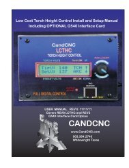
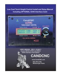
REAR PANEL FEATURES<br />
Single 9 Pin Cable interface to the MPG101B<br />
OPTIONAL Hand Controller<br />
(PORT2 CARD Installed)<br />
Plug-in for<br />
UNIVERSAL POWER PAK<br />
POWER ADAPTER<br />
Common<br />
UBOB II <br />
Technology<br />
ON<br />
+5 VDC<br />
OFF<br />
INTERNAL<br />
POWER<br />
<strong>MP3000E</strong> INTRO<br />
PORT2 PASSTHROUGH<br />
(NO CONNECTION)<br />
+12 VDC<br />
AXIS I/O Out<br />
1 5<br />
6 9<br />
*<br />
to<br />
MTA100/ESP<br />
SERIAL PASSTHROUGH<br />
to<br />
ESP CONTROLLER<br />
SERIES E<br />
Single Cable interface to MTA100<br />
terminal card for interface to Motor<br />
drives of EZPlug Cards<br />
Single Cable serial interface to remote<br />
Power Supply and Drive cabinet.<br />
Gives ESP to MACH interface
Push<br />
Read<br />
Optional PORT2<br />
Expansion for<br />
Hand Controller<br />
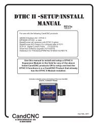
INTRODUCING THE MP3000 Master Control Unit<br />
10.062<br />
Built-in Self Test for EXPANSION<br />
Modules verifies operation<br />
Connection for REMOTE<br />
Table I/O Card for<br />
Inputs and Outputs<br />
Input for EXPANSION<br />
Modules (DTHC, SPINDLE SPEED)<br />
MP3000 INTRO<br />
MP3000<br />
Multi-Axis Interface<br />
EXPANSION<br />
MODULE<br />
TEST<br />
DTHC / SPS<br />
PORT2 OPTION<br />
INPUT<br />
Isolated Table I/O<br />
3.266<br />
1 5<br />
6 9<br />
Multi-Axis Interface<br />
SERIES E<br />
Hand Controller<br />
UBOB II<br />
Technology<br />
Port1 INPUT<br />
To PC<br />
CP PWR<br />
SERIAL INPUT<br />
To PC<br />
SINGLE PORT<br />
Interface<br />
PORT EXPANDER<br />
Technology<br />
Indicator for Charge Pump active<br />
True RS232 Serial signals<br />
Used for DTHC and ISS-02<br />
Interface to MACH<br />
Basic Features<br />
Expanded Single port interface + serial (True RS232 signals)<br />
Modular design allows for easy upgrades and easy repair<br />
Bi-directional communication with MACH3<br />
100% Digital Control<br />
Field Ungradable to DTHC or Spindle Speed with single plug-in card<br />
Custom Screens allow 100% control form MACH3<br />
Charge Pump Active Indicator<br />
Unit is plug compatible with other quality <strong>CandCNC</strong> products<br />
Buffered Step & Direction (4 or 5 axis operation options)<br />
All 8 power outputs double buffered: all 9 inputs opto isolated<br />
Rear Panel connector for MPG (hand controller)<br />
Exclusive remote Table I/O card makes hooking up homes and limits quick and easy. Two High Current relay outputs at the table where they belong.<br />
All connects made via standard data cables (DB25 & DB9)<br />
Universal Power Pak allows operation world wide<br />
Works with any TTL level step & dir type motor drives including ALL versions of Gecko drives<br />
Included interface card for multiple output options<br />
Quality components. Designed and built in the USA.<br />
Two Year Warranty Parts and Labor. Free unlimited support<br />
DTHC Features<br />
Voltage control to + - 1/4 volt<br />
Built-in self test<br />
Usable with hand or machine torches<br />
Optional Arc Good sensor for machines not equipped with that signal.<br />
Presettable volts from MACH3 screen or from Cut Profile.<br />
Unlimited Cut Profiles store/recall critical settings; Select your material from a list. Edit.Add new profiles<br />
Full DTHC operation from one screen in MACH<br />
TOTAL DC (analog) ISOLATION between Plasma (Tip Volts) and computer/controller logic<br />
On-the-fly push button adjustment for Preset Volts allows dynamic height adjust<br />
New “TIP SAVER” feature has Head Lock to prevent diving on turns or over voids<br />
Last setting retained on power down<br />
Advance Digital Torch Height Controller responds thousands of times per second<br />
Advanced logic functions like Auto THC enable, Torch off on Fault, Stop on fault, etc<br />
Optimized for use with touch-n-go surface sensing<br />
Compatable with SheetCAM
The setup of the MP3000 <strong>Series</strong> Interface involves the installation of<br />
MACH3 software and some support files on the PC to be used for the<br />
machine controller. While we will guide you through the setup for MACH3<br />
the MACH3 manual gives more in depth instructions on each feature.<br />
Familiarize yourself with the controls on the MP3000 and with the loading<br />
and operation of MACH3 with the proper profile. The initial part of this<br />
manual is devoted to getting MACH3 properly installed with the right<br />
support files and profile to run the MP3000. After you have the software<br />
installed and the cables and satellite cards hooked up you will be guided<br />
through a series of tests to determine if everything is working. We ask that<br />
you go through the setup and manual in the order presented. If at some<br />
point you cannot get the expected results and check your connections and<br />
setup with no success then call our tech support person (also the engineer,<br />
assembler, tester, webmaster and marketing guy!) at 903-364-2740. While<br />
we work a lot of strange hours we may not always be available to answer<br />
the call so leave a detailed message of the problem and how to get in touch<br />
with you will hear back from one of the staff.<br />
GENERAL SETUP<br />
Installation and setup of your MP3000.<br />
There are a series of steps you must complete to setup and interface the<br />
MP3000 with your PC and Your Plasma torch<br />
Install and setup the Primary parallel port in your PC<br />
Setup and configure the first serial port (COM1) on your PC<br />
Install MACH3 software<br />
Copy your MACH3 license into the MACH3 main folder<br />
Run the install program from the <strong>CandCNC</strong> disk to load custom<br />
screens and setup files and Plug-ins<br />
Open MACH3 and check screens and configure the PLUG-INs<br />
Connect the 2 PC port cables (one 25Pin, one 9 Pin) to the front of<br />
the MP3000<br />
Connect the Table I/O card to the Table I/O port on the front of the<br />
MP3000<br />
Connect the Axis I/O Card to the motor drive modules, or the EZPlug<br />
Gecko cards (stepper or servo) via the provided MTA100 Card<br />
Run a quick series of tests to confirm the ports are working and that<br />
MACH3 is configured correctly<br />
Do final checkout.<br />
Setup and test any Expansion Cards (DTHC or Spindle Speed)<br />
Fire up the machine and cut a test file.
INSTALL and SETUP PRIMARY and/or SECONDARY PARALLEL<br />
PORTS<br />
NOTE: USE THIS SECTION ONLY IF YOUR PC DOES NOT HAVE A BUILT-IN<br />
PARALLEL PORT and/or SERIAL PORT OR YOU HAVE PURCHASED THE<br />
MPG101B HAND CONTROLLER THAT USES A SECOND PARALLEL PORT.<br />
Use the same procedure to install a primary (PORT1) Parallel Port (if your<br />
PC does not have one) or a second port. Do not attempt to use two<br />
separate parallel port cards of the same type to get two ports. For two<br />
ports use a Dual Parallel Port card. <strong>CandCNC</strong> stocks low cost parallel and<br />
parallel/serial PCI expansion cards.<br />
PC HARDWARE SETUP<br />
Make sure the card you install has drivers for the version of Windows you are<br />
running. Win2000 drivers may or may not work in XP (or visa versa). When you<br />
install the card in your computer and turn it back on, it should find the new<br />
hardware and when prompted, you should use the disk that comes with the port<br />
card to install the correct drivers. There should be instructions with the card on<br />
the proper way to install the drivers.<br />
After you install the parallel port and Windows recognizes the port(s) then open<br />
the device manager from the Hardware section under Windows /Control<br />
Panel/System and open the Ports icon and find the Port entries. Open that and<br />
click on the resources tab.<br />
Write down the first number in the Input/Output range (DE00 in this case above). We will<br />
have to enter that number in the MACH3 setup procedure later
INSTALL and SETUP PRIMARY and/or SECONDARY PARALLEL<br />
PORTS<br />
PC HARDWARE SETUP<br />
You will have to setup the COM1 serial port in Windows. It should be setup with<br />
9600 baud, 8 bits, no parity, 1 stop bit, no Flow control.<br />
Testing: We will test the functionality of the com port after we hook up the<br />
MP3000 to the computer.
INSTALL MACH SOFTWARE<br />
Software Install Instructions<br />
If you are installing from the Support CD you can find the MACH3 ver 3.042.020 in the BladeRunner\MACH-<br />
PROG folder as Mach3VersionR3.042.exe. If you are installing from a web download you will first have to UNZIP<br />
the files you downloaded and place them in a Folder on your PC. Name the folder something that you can easily<br />
identify later. Unzip the files all into that folder (MACH3 program, BladeRunner-Install.exe, etc)<br />
While MACH will run under Windows Vista a lot of other programs you may need won’t. Vista uses LOT’s of<br />
resources so your PC needs to be the fastest one with 2G of RAM to have a shot at making it work. We do not<br />
currently support Vista so PLEASE don’t call and ask for support for MACH from us if you are running anything<br />
but WIN2000 or XP (any level).<br />
PC SOFTWARE SETUP<br />
A NOTE ABOUT HARDWARE (PC) THAT YOU NEED TO RUN MACH:<br />
1. Not all hardware is compatible with MACH3 regardless of how fast the PC is. It’s rare that a PC rated over<br />
1.8GHZ won’t run MACH but not unheard of. Usually the problems show up as jerky motor movements, bad<br />
motion in running code and other control problems. Things like Inputs and Outputs and not getting any motor<br />
movement is NOT typically a MACH / PC issue. If in doubt about the ability of the PC run DriverTest.exe (With<br />
MACH not running) located in the MACH3 folder.<br />
2. The minimum computer recommended is a 1 GHZ processor with 256MRam. We find that a 1.8 or 2.4 GHZ<br />
with 512M RAM tends to work better especially if the MB has on-board video. The higher you can run the core<br />
freq in MACH the more Steps per Second you can get and the smoother the pulse train of those steps. There<br />
are also Windows processes that can effect the timing in MACH. Never run realtime virus protection or other<br />
“tray” programs not needed for basic Windows functions.<br />
Start Install of MACH3 software by clicking on the MachProgram/ MACH3ver3.042.020.exe file . If you already<br />
have a version of MACH on the PC, you will be prompted to upgrade the version. Let it upgrade. If you have a<br />
version NEWER than 3.042.20 then be aware that while there will probably be no problems we have not tested<br />
the custom drivers (plug-ins) with versions after 3.42.020. You will see the screen above when you start the<br />
install.
About the MACH3 License<br />
You must copy your MACH3 license (provided when you purchase a full copy<br />
from the Mach3 website or from an authorized dealer) into the main MACH3<br />
folder. A MACH2 license will work as well. You can check to make sure your<br />
license is active by re-loading MACH3 after the license copy and opening the<br />
Help/About and making sure the “licensed to” line is NOT “Demo”. The<br />
<strong>MP3000E</strong>-DTHC( THC functions) WILL NOT WORK WITH A DEMO copy of the<br />
software. The other motor drive functions will work. If you cannot get the THC<br />
button to show active (green LED), then check your copy to make sure the<br />
license is there. If you upgrade the version, the license will remain but if you<br />
manually remove the MACH3 folder or change it’s name prior to loading a new<br />
copy the license file will have to be re-installed into the working directory.<br />
PC SOFTWARE SETUP<br />
Setting up the Port 2 address. (Used only if you have installed a second<br />
parallel port) for use with the MPG101B Hand Control. The new UBOB<br />
interface card used in all <strong>CandCNC</strong> products has a Port Expander that<br />
increases the number of IO signals and eliminates the need for a second<br />
parallel port unless you are adding the optional Hand Controller. It’s<br />
recommended you do not install the Hand Control unit until you have the<br />
MP3000 working correctly and cutting from the screen and keyboard.<br />
Within MACH3 on the Ports and Pins/ Port Setup and Axis Selection tab:<br />
<br />
<br />
<br />
<br />
If you are using a motherboard parallel port for PORT1 , confirm the<br />
address is 0X378 in PORT address box in MACH<br />
If you are using a PORT1 or PORT2 expansion card, Enter the hex<br />
address you recorded earlier for your parallel port(s). The actual address<br />
you have written down should be proceeded by a<br />
”0X” (Zero, X) so something like DE00 becomes 0XDE00 for the input<br />
value (or 0xde00 will work since the value is not case sensitive)<br />
For PORT2 installs Make sure the “Use Pins 2-9 as Inputs” box is checked<br />
If the port1 address is correct the CP (Charge Pump) LED should be on<br />
when MACH3 is out of RESET. If it does not come on, then Port 1 may not<br />
be working correctly. We have found that some older Parallel Port add-in<br />
cards do not work properly with XP. Make sure your card has specific<br />
drivers for the version of Windows you are running.
Tree structure of Support CD: Root Folder<br />
PC SOFTWARE SETUP<br />
INSTALLING <strong>CandCNC</strong> Custom drivers, profiles and screen sets.<br />
The Support CD has a folder named AUTO INSTALL FILES. Under that are two folders. One is<br />
CurrentProducts. Open that folder and you will see the auto-install files for the various<br />
products. For any <strong>MP3000E</strong> product run the <strong>MP3000E</strong> -Instal.exe FIRST. If you have the<br />
MP3000-DTHC or are adding the DTHC module to your existing MP3000-Basic then run the<br />
<strong>MP3000E</strong>-UBOBII-DTHC_Install AFTER the <strong>MP3000E</strong>-Instal file.<br />
.<br />
The <strong>MP3000E</strong>-Instal.exe Auto Install does the following:<br />
Installs the custom MACH XML (Profile) and SET (Screen file) files into the MACH3 directory<br />
Installs 2 custom Plug-ins used in all of <strong>CandCNC</strong>’s products .<br />
Adds in the proper side files for the screen files (embedded VB)<br />
Removes the default Icons MACH installs on the Desktop (except for LOADER) and puts a MP3000 Icon on<br />
the Desktop so you can start your MP3000 directly from that ICON.<br />
Removes unneeded XML’s from MACH so they don’t show up in the Loader List.
Load and Testing MACH<br />
After you have installed MACH and run the <strong>MP3000E</strong>_INSTALL on the Support CD, open<br />
MACH using either the MACH Loader and the MP3000-Base selection from the list OR<br />
using the MP3000-Basic Icon created in the desktop.<br />
You should see the following screen or something very close. If you are missing the icon or<br />
it’s not in the selection list, re-run the <strong>MP3000E</strong>-INSTALL again. If you have the Profile<br />
(MP3000-Basic) listed in the MACH Loader and the screen does not display go to the top<br />
menu bar and select VIEW/Load Screens and naviagate to the MACH3 folder and select<br />
MP3000-Basic.set. If it is missing any of the Bitmaps (picture buttons and/or backgrounds<br />
then confirm the Installer created the <strong>CandCNC</strong> folder under the MACH3/Bitmaps Folder<br />
and there are files in that folder. We have included a ZIp file on the CD of all the bitmaps<br />
and the ZIP file is on the <strong>CandCNC</strong>Support Forum site in the FILES/MP3000 Support Files<br />
Folder. You can UNZIP the files in the Bitmaps.ZIP file directly to the<br />
MACH3/Bitmaps/<strong>CandCNC</strong> folder. Along with bitmaps and other features the MP3000<br />
screens contain several custom functions embedded as code behind certain buttons. If you<br />
elect to use another screen SET file with the MP3000 be aware some functions may not<br />
work.<br />
PC SOFTWARE SETUP
Setting up and confirming Parallel addresses in MACH<br />
PC SOFTWARE SETUP<br />
NOTE: Each PROFILE (XML) you setup in MACH has it’s own separate set of<br />
settings (config) it maintains, so any changes or additions to a setup changes<br />
the profile and ONLY that profile. So, adding in a port profile, tuning motors,<br />
changing a pin function, etc, is saved only in the profile you have loaded.<br />
If you<br />
have multiple profiles you will need to make the listed changes/setup in each<br />
one.<br />
Checking PORT1 and (optional) PORT2 Setup in MACH CONFIG<br />
NOTE: Not all computers will run with a Kernel Speed greater than 35000HZ. If you start<br />
MACH after loading our Auto Install (see next page) and MACH locks ups you may need<br />
to run at a lower Kernel Speed. We have modified the install to set the default Kernel<br />
Speed at 45000. You will need to increase that speed if you are running a servo based<br />
system and you need more Pulses per Second to get the RPM from the motors.<br />
Example: With 500 line encoders (2000 pulses per rev) you will need 66,000 pps to<br />
produce 2000 RPM of the motor. Pulse rates over 60,000 need to be tested with a<br />
specific computer to verify it can operate at that Kernel Speed.
MACH Setup<br />
CHECKING PLUG-IN LOAD<br />
The auto install program should load<br />
the ccc_comm and ccc_UBOB plug-ins<br />
and Enable them. Some installs will<br />
also load the ccc_pendant as well. If<br />
you do not have an MPG101B Hand<br />
Controller then disable (RED X) the<br />
ccc_pendant plug-in if it is Enabled.<br />
Open the CONFIG (yellow tab) on the<br />
ccc_comm and set your environment<br />
up to match the products you are<br />
running. You can start with “Neither”<br />
in both selection lists. Later if you add<br />
the DTHC or Spindle Speed Modules<br />
the install SHOULD change the settings<br />
but always check to make sure the<br />
changes were made. If you have a<br />
DTHC (MP3000-DTHC) and have loaded<br />
the DTHC upgrade install and the DTHC<br />
does not appear to be communicating<br />
with the screen (MACH) check the<br />
settings in the ccc_Comm plug-in.<br />
There are currently no settings to<br />
change in the ccc_UBOB plug-in
PC<br />
Single DB9 Cable<br />
Parallel<br />
Ports<br />
MP1000 Master Controller Interface Block Diagram<br />
Single DB25 Cable<br />
TABLE I/O<br />
REMOTE<br />
TABLE I/O<br />
CARD<br />
Mounted on table<br />
Table Limits<br />
Homes<br />
Safety<br />
Remote E-Stop<br />
30A Relay<br />
15A Relay<br />
15A Relay<br />
Mounted at plasma or VFD<br />
THC<br />
SENSOR<br />
FIGURE 5<br />
Sensor Cable<br />
Serial<br />
Port<br />
MP3000 Interface Control<br />
NOTE: Entire MP3000 can be installed inside the<br />
Power Control Enclosure. A<br />
Special mounting plate and kit is<br />
available from <strong>CandCNC</strong><br />
AXIS I/O<br />
Single DB9 Cable<br />
Single DB25 Cable<br />
OR<br />
SPINDLE<br />
SPEED<br />
POWER SUPPLY<br />
MOTOR DRIVES<br />
To Table Motors<br />
MP3000 Setup
MP3000 Interface Control<br />
MP3000 to Power Supply & Motor Drivers<br />
Note: ESP & EZPlug modules<br />
are sold<br />
as separate items<br />
FIGURE 6<br />
Note: MTA100 Extension Card comes with<br />
MP3000 Units<br />
Single DB25 Cable<br />
AC Line IN<br />
MTA100<br />
CARD<br />
Main Switch<br />
REMOTE Power<br />
& Motor Drive<br />
Box<br />
ESP Smart Power<br />
Module<br />
Motor DC<br />
Buffered<br />
Step & Dir<br />
X5<br />
EZPLUG<br />
Stepper/servo<br />
cards<br />
Main Fuse<br />
Components Available<br />
from <strong>CandCNC</strong><br />
FAN<br />
MOTOR<br />
DRIVER<br />
MOTOR<br />
DRIVER<br />
MOTOR<br />
DRIVER<br />
MP3000 Setup
HARDWARE SETUP<br />
Plugging in Universal Power Pak<br />
Checking PWR LED<br />
Installing External I/O Cards<br />
<br />
<br />
<br />
TABLE I/O Setup (Homes, Limits, Relays)<br />
MTA150 Setup (Motor Driver, S&D signals)<br />
Motor Driver Options<br />
Setting up outputs<br />
OPTIONAL PORT2 Interface (port 2 signals)<br />
Connecting MP3000 to<br />
Wiring options fo<br />
MP3000 Setup
MP3000 Setup<br />
INPUT POWER<br />
100 - 240VAC 50/60 HZ<br />
Standard IEC<br />
POWER Cord<br />
Use correct cord for<br />
Plugs in your country<br />
For UBOB Builders Kits the plug must be removed (cut off)<br />
and the wires stripped back for use with the input screw<br />
terminals on the UBOBII card (see illustration). There are 4<br />
wires + a shield. The two Yellow rires are BOTH + 12VDC.<br />
The Two RED wires are BOTH +5VDC. The sheild is<br />
Ground (common) for all 4 power wires. See the power<br />
hookup on next page.<br />
Cord supplied is for North America<br />
AC Plugs (120 60HZ)<br />
If you are using the MP3000 on another voltage (like 220VAC 50HZ) you<br />
will need to change out the plug on the end of the supplied cord. You<br />
can also use an IEC cord with the proper connector to fit the wall socket<br />
you need to connect to. IEC cords are the same cords used on Personal<br />
Computers. There are no switches or settings to change on the Power<br />
Pak when changing voltages of line frequency.
Push<br />
Read<br />
Plugging in the International Power Pak to the MP3000<br />
The Mini-DIN plug on the Power Pak has 4 pins inside a<br />
circular connector. The plug has a locator pin and only plugs<br />
in one way. Rotate the plug unit it fits the POWER ADAPTER<br />
input jack and plug it completely in. Make sure the AC Cord is<br />
in the other end of the Power Pak and the unit is plugged into<br />
a live AC socket. After you plug in the DIN connector. Turn on<br />
the INTERNAL POWER swtich and turn the MP3000 around so<br />
you can see the front. Confirm that the Green PWR Led is ON.<br />
It should turn on and off when the INTERNAL POWER Switch<br />
is turned ON/OFF<br />
MP3000 Setup<br />
Plug-in for<br />
UNIVERSAL POWER PAK<br />
UBOB II<br />
Technology<br />
POWER ADAPTER<br />
Common<br />
+12 VDC +5 VDC<br />
1 5<br />
PORT2 PASSTHROUGH<br />
(NO CONNECTION)<br />
AXIS I/O Out<br />
ON<br />
OFF<br />
INTERNAL<br />
POWER<br />
6 9<br />
SERIES E<br />
SERIAL PASSTHROUGH<br />
to<br />
ESP CONTROLLER<br />
to<br />
MTA100/ESP<br />
MP3000<br />
Multi-Axis Interface<br />
EXPANSION<br />
MODULE<br />
TEST<br />
DTHC / SPS<br />
PORT2 OPTION<br />
INPUT<br />
Isolated Table I/O<br />
1 5<br />
6 9<br />
Multi-Axis Interface<br />
SERIES E<br />
Hand Controller<br />
UBOB II<br />
Technology<br />
Port1 INPUT<br />
To PC<br />
CP PWR<br />
SERIAL INPUT<br />
To PC<br />
PWR should be on when rear<br />
Switch is ON. CP lamp DOES<br />
not light until MACH is<br />
connected to PC and MACH is<br />
out of RESET
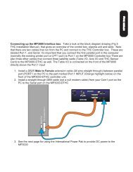
MP3000 Setup<br />
Connecting up the MP3000 Interface box. Take a look at the block diagram drawing (Fig 5<br />
THC Installation Manual), that gives an overview of the control box, plasma unit and table. Note<br />
that there are two cables that run from the PC and connect to the THC Controller box. These are<br />
labeled Port 1, and Serial It’s important that you connect the first parallel port in the computer<br />
(normally the existing printer port or LPT1 port) to Port 1 on the MP3000 Controller box There are<br />
also three other cables that connect three satellite cards (Table I/O, Axis I/O and THC Sensor<br />
Card) to the MP3000-DTHC as well. The Table I/O is connected on the front of the MP3000<br />
directly above the Port 1 input<br />
1. Install a DB25 Male to Female extension cable (All pins straight through) between parallel<br />
port (PORT1 on the PC to the part marked Port 1 INPUT (Orange highlight below) on the<br />
front of the MP3000-DTHC controller unit.<br />
2. Install a straight through DB9 cable (not a null modem cable) from your Com1 port on the<br />
PC to the Serial port on the MP3000-DTHC<br />
Serial Port<br />
PC Parallel Port 1<br />
3. See the next page for using the International Power Pak to provide DC power to the<br />
MP3000
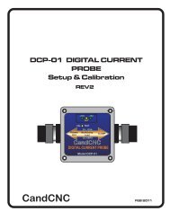
Installing the Table I/O Card.<br />
We have provided a functional remote breakout card to use as your interface at the<br />
machine to connect the Home and any limit switches via crimp-on connectors. The<br />
Table I/O card has status LED's for each main signal mounted on the card so you can<br />
see and test the switch functions. The Table I/O is a way to easily connect all of your<br />
I/O at one point. Since the Card can be mounted remote from the MP3000 Interface<br />
box the multitiude of wires at the table need only pull to the Table I/O card.. While the<br />
card will mount inside the main control cabinet it requires a lot less wire and wire<br />
routing to put it at the table and use a single DB25 to connect it to the MP3000.<br />
MP3000 Setup<br />
K3 MAIN RELAY<br />
20A COM<br />
Normally OPEN<br />
Terminal<br />
K3 MAIN RELAY<br />
20A COM<br />
Terminal<br />
Isolated<br />
INPUTS<br />
PORT 1<br />
Inputs<br />
K4 Aux RELAY<br />
20A COM & NO<br />
Terminals<br />
EPO<br />
Jumper for<br />
operation<br />
BHome and AUX<br />
inputs [PORT 2]<br />
only<br />
IDC Header for<br />
DB9 adapter.<br />
Quad Relay<br />
Expansion Plug<br />
The TABLE I/O CARD MUST be attached to the Table I/O Input plug on the Front of the MP3000 or you will not be<br />
able to bring MACH3 out of RESET. You MUST have a jumper (or NC switch) across the EPO jumpers on the card<br />
(see diagram next page) to bring MACH out of reset. You do NOT have to have the Homes or any other inputs or<br />
outputs hooked up to run MACH.
TABLE I/O II CARD<br />
The TableI/O card provides a breakout of inputs and outputs. It connects to the UBOB/MP3000 via a 25<br />
pin computer cable into the TABLE I/O plug (see overlay next page). The card can be close to or up to<br />
20ft from the UBOB/MP3000. You have the option to mount the card close to the UBOB, with the Motor<br />
drivers in the main controller box, and pull the Homes and other inputs into the card, or you can mount the<br />
card out on the Table and connect all of the inputs with short runs. Having the Power relays out on the<br />
table for larger machines can be an advantage.<br />
MP3000 Setup<br />
HOME INPUTS<br />
Use Normally Open<br />
Switches.<br />
X - A Home are port 1<br />
inputs<br />
Limits are typically<br />
setup as normally<br />
closed and connected<br />
in series at the<br />
switches with<br />
beginning and end of<br />
string into the LIMITS<br />
Tabs.<br />
The DOWN, UP and<br />
ARC OK inputs are<br />
also Port 1 inputs and<br />
can be used for any<br />
switch type input.<br />
The EPO is the E-stop<br />
(software) input. IT<br />
HAS TO BE CLOSED.<br />
A JUMPER IS<br />
NEEDED IF IT”S NOT<br />
USED WITH A NC E-<br />
stop Button (not<br />
T12<br />
C2<br />
T14<br />
T16<br />
C4<br />
T18<br />
C5<br />
C8<br />
T7<br />
T6<br />
C7<br />
T8<br />
C6<br />
T9<br />
Xhome<br />
YHome<br />
ZHome<br />
AHome<br />
LIMITS<br />
C9<br />
DOWN<br />
AUX0 UP<br />
T13<br />
T15<br />
C3<br />
T17<br />
T19<br />
T2 T3 T4<br />
T5<br />
K3<br />
LIMITS D2<br />
K3<br />
NO<br />
Com1<br />
AHome<br />
K3<br />
52<br />
EPO<br />
ARC OK<br />
R1<br />
K5 D15<br />
ARC OK<br />
D9<br />
UP<br />
C1<br />
K4<br />
AUX1<br />
BHOME<br />
D3<br />
K4<br />
AUX2<br />
AUX4<br />
DANGER!<br />
DANGER!<br />
J2<br />
1<br />
13<br />
PLUG<br />
Xhome<br />
YHome<br />
ZHome<br />
50<br />
DWN<br />
AUX0<br />
T20<br />
49<br />
T10<br />
T21<br />
T11<br />
6<br />
1<br />
J1<br />
C14<br />
J9<br />
J10<br />
J6<br />
J8<br />
10<br />
J33<br />
14<br />
25<br />
K4<br />
J4<br />
J7<br />
AUX3<br />
C&CNC<br />
47 TABLE I/O<br />
REV 6<br />
J18<br />
J5<br />
NO Com2<br />
C13C12<br />
C11<br />
J13<br />
C10<br />
QUAD RELAY<br />
J12<br />
J11<br />
K3<br />
Main Relay Output<br />
20A Normally open<br />
contacts<br />
See hook up details for<br />
driving external loads<br />
K4<br />
Secondary Relay 10A<br />
Normally open contacts.<br />
See hook up details for<br />
driving external loads.<br />
AUX 0 - AUX4 and B Home<br />
are PORT2 inputs and only<br />
work if you have the<br />
optional Port 2 card<br />
installed and a 2nd parallel<br />
port on thePC active and<br />
LED’s are indicators that the circuit is working when a switch is<br />
closed. They only come on if the Table I/O is connected to the<br />
UBOB and the UBOB is powered up. You can short across an<br />
input Pair (example: T12 to T13 for X Home. The LED should light<br />
and the X Home Screen LED in MACH for X Home should light.<br />
The LED is in series with the Input Opto and is a good indication
C5<br />
C8<br />
C7<br />
C6<br />
J2<br />
Xhome<br />
YHome<br />
ZHome<br />
LIMITS<br />
1<br />
AHome<br />
DWN<br />
AUX0<br />
14<br />
UP<br />
K3<br />
D2<br />
D9<br />
K5<br />
C1<br />
ARC OK<br />
6<br />
1<br />
D15<br />
K3<br />
D3<br />
K4<br />
R1<br />
QUAD RELAY<br />
10<br />
K4<br />
25<br />
13<br />
NO<br />
Com1<br />
J18<br />
J5<br />
C11<br />
Home and limit switch hook ups<br />
Typical connections for Homes and Limits<br />
MP3000 Setup<br />
All of the inputs are opto isolated and map to a<br />
specific pin on the parallel port(s). In reality you can<br />
use any input for any signal. Inputs are not fast<br />
enough for Encoder feedback faster than a few<br />
pulses per second. The inputs use a “floating” ground<br />
(+12 return). If you need more inputs than the 8 (9<br />
with EPO) then a PORT 2 card can be hooked to the<br />
UBOB and the added Aux and BHome inputs will<br />
work with a second parallel port.<br />
Normally closed contacts<br />
For far limits. Wired in series<br />
NC NC NC<br />
C C C<br />
YHome<br />
JUMPER EPO to be able to<br />
bring MACH out of RESET<br />
C<br />
ZHome<br />
NO<br />
C<br />
NO<br />
C<br />
XHome<br />
NO<br />
PLUG<br />
T9<br />
AUX0 UP<br />
T5<br />
T8<br />
T7<br />
DOWN<br />
C9<br />
T6<br />
LIMITS<br />
T2 T3 T4<br />
T18<br />
AHome<br />
T19<br />
C4<br />
T16<br />
ZHome<br />
T17<br />
C3<br />
T14<br />
YHome<br />
T15<br />
C2<br />
T12<br />
Xhome<br />
T13<br />
52<br />
J9<br />
C14<br />
J1<br />
T20<br />
EPO<br />
T21<br />
K4<br />
T10<br />
ARC OK<br />
T11<br />
BHOME<br />
J10<br />
J8<br />
C10<br />
AUX1<br />
J13<br />
J6<br />
C13C12<br />
AUX4<br />
J33<br />
C&CNC<br />
47 TABLE I/O<br />
REV 6<br />
AUX2<br />
J12<br />
J7<br />
AUX3<br />
J11<br />
NO Com2<br />
J4<br />
48<br />
R2<br />
DANGER!<br />
DANGER!<br />
QUAD RELAY HEADER<br />
is for an optional quad relay card<br />
and adds 4 more relays to the outputs.
C5<br />
C8<br />
C7<br />
C6<br />
J2<br />
Xhome<br />
YHome<br />
ZHome<br />
LIMITS<br />
1<br />
AHome<br />
DWN<br />
AUX0<br />
14<br />
UP<br />
K3<br />
D2<br />
D9<br />
K5<br />
C1<br />
ARC OK<br />
6<br />
1<br />
K3<br />
D3<br />
K4<br />
R1<br />
QUAD RELAY<br />
K3<br />
10<br />
K4<br />
25<br />
13<br />
NO<br />
Com1<br />
J18<br />
J5<br />
C11<br />
Outputs for 2 low<br />
Current Relays<br />
QUAD RELAY EXPANSION CARD<br />
6 RELAY SETUP USING OPTIONAL QUAD RELAY EXPANSION CARD<br />
or QUAD RELAY BOX<br />
K2<br />
K5<br />
See Quad Relay Manual for Connection details<br />
+<br />
D9<br />
K3<br />
A PLUG HOT<br />
J3<br />
BREAKER A<br />
B PLUG HOT<br />
J10<br />
K4<br />
BREAKER B<br />
J8<br />
J9<br />
BREAKER A & B<br />
PLUGS NEU<br />
J7<br />
SFTY GND L2 HOT<br />
J14<br />
L1 NEU<br />
MP3000 OPTION<br />
+<br />
33<br />
J17<br />
J2<br />
SKT<br />
1<br />
Not Used<br />
34<br />
Db9 Fem to DB9 Male EXTENSION CABLE<br />
up to 25ft can be used<br />
IDC 10 to DB9 Male<br />
Adapter<br />
PLUG<br />
T9<br />
AUX0 UP<br />
T5<br />
T8<br />
T7<br />
DOWN<br />
C9<br />
T6<br />
LIMITS<br />
T2 T3 T4<br />
T18<br />
AHome<br />
T19<br />
C4<br />
T16<br />
ZHome<br />
T17<br />
C3<br />
T14<br />
YHome<br />
T15<br />
C2<br />
T12<br />
Xhome<br />
T13<br />
52<br />
50<br />
J9<br />
C14<br />
J1<br />
T20<br />
EPO<br />
T21<br />
K4<br />
T10<br />
ARC OK<br />
T11<br />
49<br />
BHOME<br />
J10<br />
J8<br />
C10<br />
AUX1<br />
J13<br />
J6<br />
C13C12<br />
AUX4<br />
J33<br />
AUX2<br />
J12<br />
DANGER!<br />
DANGER!<br />
47<br />
C&CNC<br />
TABLE I/O<br />
REV 6<br />
J7<br />
AUX3<br />
J11<br />
NO Com2<br />
J4<br />
48<br />
R2
USING OUTPUT RELAYS<br />
TABLE IO CARD II<br />
Connect Safety ground (GreenWire) on equipment that has three conductors<br />
DANGER: High Voltage present.<br />
Do not connect with power applied<br />
Hot (L1)<br />
Use wire size rated<br />
for the continuous current of the load<br />
#16 up 5A (10A peak)<br />
#14 up 10A (15A peak)<br />
#12 up 15A (15A peak)<br />
SPST Relay<br />
K3<br />
NO<br />
Main Output<br />
Normally Output 1 for spindle motors<br />
20A @240VAC Max<br />
#10 up 25A (35A peak)<br />
#8 up 35A (45A peak)<br />
SPDT<br />
NC<br />
C<br />
NO<br />
10A Max<br />
High Current Load (up to 20A)<br />
Note: Current ratings for wires are approximation ONLY.<br />
Factors such as ambient temps, insulation type, length<br />
of run, bundled or unbundled, etc. make exact ratings difficult.<br />
Use this as a general guide only and follow the recommendations<br />
of your equipment manufacturer. Use at least the wire<br />
size of the equipment cord. Use commercial splices and<br />
heatshrink on all terminals or a sealed electrical box.<br />
Load can be any AC inductive (motors) or resistive (lights) load<br />
up to 20A.<br />
Outputs K4 are rated to 10A max.
PLUG<br />
X - Y<br />
1<br />
J5<br />
1<br />
2<br />
1<br />
Z - A<br />
J19<br />
S&D Test<br />
AXIS I/O IN<br />
AXIS I/O IN<br />
14 25<br />
1<br />
B - Y'<br />
13<br />
J1<br />
Encoder V<br />
5V Source<br />
INSTALLING the MTA150 (Axis I/O) Card for interface to Motor Drives and EZPlug<br />
Gecko Interface Cards (sold separately)<br />
The MTA100 card is supplied wih all MP3000 series units. If you have ordered a<br />
Complete Electronics Package (PlazPak, RouterPak or MillPak) then the MTA150 is<br />
already mounted inside the Enclosure and has a DB25 access plug externally. The<br />
following instructions are based on the MP3000 being sold as a stand-alone<br />
product and shows how to use the MTA150 to connect discrete motor drives or the<br />
<strong>CandCNC</strong> EZPlug Stepper or Servo Interface cards using single cables for up to 6<br />
drives. If you have the Complete Electronics Package you can skip this section on<br />
the MTA150 Setup and testing.<br />
MP3000 Setup<br />
THE MTA150 connection plug is on the back of the MP3000 and labled as the AXIS<br />
I/O . It takes a single MALE to FEMALE DB25 Extension Cable up to 20Ft long. In<br />
most circumstances the MTA150 card will be mounted in the same case as the<br />
Motor Drives and Power Supply. If you are building a single box control cabinet<br />
and you are embedding the MP3000 outside it’s case inside the enclosure, you can<br />
get a short 26 pin IDC cable to interface directly between the AXIS I/O plug on the<br />
UBOB and the MTA100 card. Please contact us to order the part or check the<br />
website.<br />
Since the MP3000 can be the front-end in a wide variety of motor driver<br />
configurations we are including several pages of different hookup possibilities.<br />
These will cover most applications.<br />
DB25 Cable FEMALE end<br />
G540 INTERFACE<br />
Dir<br />
B<br />
STEP<br />
U6<br />
J55<br />
S<br />
D<br />
J52<br />
1<br />
1<br />
B Axis<br />
J3<br />
S<br />
<strong>CandCNC</strong><br />
MTA150<br />
REV4<br />
S<br />
D<br />
S<br />
D<br />
1<br />
X<br />
Y<br />
Z<br />
To AXIS I/O<br />
on Rear of<br />
MP3000<br />
S<br />
D<br />
D<br />
1 PC +5<br />
A<br />
2<br />
1<br />
ESP Interface<br />
20<br />
19<br />
J34<br />
2<br />
10<br />
1<br />
9<br />
PCGND PCGND<br />
J2<br />
REV2<br />
MTA150 Mounted Remotely in Drive / Power<br />
Enclosure
PLUG<br />
X - Y<br />
1<br />
J5<br />
1<br />
2<br />
1<br />
Z - A<br />
J19<br />
S&D Test<br />
AXIS I/O IN<br />
AXIS I/O IN<br />
14 25<br />
1<br />
B - Y'<br />
13<br />
J1<br />
Encoder V<br />
5V Source<br />
MTA150 Card not used<br />
in BladeRunner<br />
MTA150 Motor Driver Interface Card<br />
The MTA 100 provides a remote (or local) breakout card to access the 5 sets of step & dir signals from<br />
the MP3000 AXIS I/O Port . When placed in a separate cabinet with the Motor Drivers and/or power<br />
supply, the MTA150 can be mounted so the DB25 connector (AXIS I/O In) can be used with a standard<br />
M-F DB 25 extension cable and IDC Adapter at the UBOBII Axis I/O Header to make avaialble all the<br />
signals for using Step & Direction based drives. The Card also has additional connectors that provide<br />
interface to an external G540 4 axis Gecko Driver product and headers to plug in <strong>CandCNC</strong> EZPlug®<br />
Stepper or Servo Interface cards. Axis I/O interface to the UBOBII can also be via the 26 pin IDC<br />
header behind the DB25 connector labeled as AXIS I/O. 5th Axis (B) signals are provided using the B<br />
channel signals from the UBOBII but independent 5 axis motion (not hardware slaved) requires a 2nd<br />
parallel port card. The following pages show several different type of hookups to common motor drives<br />
and to our EZplug cards. The are for illustration only and should be used as guides.<br />
MP3000 Setup<br />
G540 INTERFACE<br />
B<br />
Dir<br />
STEP<br />
U6<br />
S<br />
D<br />
J52<br />
1<br />
1<br />
<strong>CandCNC</strong><br />
MTA150<br />
REV4<br />
1<br />
1 PC +5<br />
+5<br />
+5<br />
X<br />
Y<br />
Z<br />
A<br />
STEP<br />
Dir<br />
STEP<br />
Dir<br />
STEP<br />
Dir<br />
STEP<br />
Dir<br />
For +5 Common Drives<br />
Screw Terminals for<br />
Hard wiring Drives<br />
(non-EZPLUG)<br />
PCGND<br />
PCGND<br />
PCGND<br />
PCGND<br />
For GND Common Drives<br />
(Gecko 203)<br />
MTA100<br />
REV2<br />
J55<br />
S<br />
Z<br />
A<br />
2<br />
1<br />
20<br />
19<br />
10<br />
2<br />
9<br />
1<br />
J2<br />
B Axis<br />
J3<br />
D<br />
S<br />
S<br />
D<br />
S<br />
D<br />
D<br />
X<br />
Y<br />
ESP Interface<br />
J34<br />
PCGND<br />
PCGND<br />
J1: Sets the source of 5V for Servo Card Encoder.<br />
CAUTION DO NOT CHANGE THIS UNLESS YOU ARE<br />
TOLD to DO SO. This option is for systems running<br />
encoders that draw more than 50ma.<br />
Ours do not. It is USED ONLY WITH SERVO SYSTEMS
D<br />
S<br />
D<br />
S<br />
D<br />
S<br />
D<br />
J2<br />
J55<br />
J34<br />
<strong>CandCNC</strong><br />
S MTA150<br />
REV4<br />
B Axis<br />
1<br />
1<br />
J52<br />
S<br />
D<br />
ESP Interface<br />
U6<br />
G540 INTERFACE<br />
MOTOR POWER AND ENCODER (Servo models) CONNECTIONS<br />
NOT SHOWN<br />
MTA100 Mass Termination Adapter<br />
X MOTOR<br />
GECKO<br />
S<br />
LOW Cost Interface with discreet wiring<br />
201<br />
320<br />
D<br />
COM<br />
GECKO<br />
X<br />
Y MOTOR<br />
Dir<br />
PLUG<br />
201<br />
320<br />
J5<br />
Y<br />
X - Y<br />
J3<br />
STEP<br />
B<br />
1<br />
1<br />
2<br />
1<br />
Z<br />
1<br />
DB25
1<br />
2<br />
1<br />
2<br />
1<br />
X MOTOR<br />
X Encoder<br />
MTA100 Mass Termination Adapter<br />
USED WITH MP3000 DTHC, SPINDLE SPEED or<br />
BASIC<br />
GECKO<br />
<strong>CandCNC</strong><br />
EZPLUG<br />
10 pin ribbon cables<br />
10”<br />
MP3000-DTHC<br />
Gecko Servo<br />
Interface Card<br />
MP3000-SPS<br />
MP3000-BASIC GECKO<br />
10<br />
9<br />
X<br />
J25 J24 J23 J22 J21 J20 J18<br />
A Z Y<br />
X - Y<br />
J55<br />
10<br />
2<br />
1 9<br />
1<br />
9<br />
EXT Port<br />
<strong>CandCNC</strong><br />
MULTI-AXIS INTERFACE<br />
REV1<br />
J52<br />
C1<br />
MINI-IO IN<br />
1<br />
Y Encoder<br />
Y MOTOR<br />
U5<br />
AXIS I/O Plug<br />
J8<br />
J7<br />
Remote Shutdown<br />
10<br />
9<br />
J55<br />
RS<br />
S&D CARD<br />
J50<br />
Z - A<br />
2<br />
1<br />
2<br />
1<br />
D3<br />
D2<br />
D1<br />
10<br />
9<br />
5V Source<br />
J4 Encoder V<br />
J1<br />
11<br />
+5<br />
J19<br />
OR<br />
J6<br />
PC GND<br />
GECKO<br />
J5<br />
PC +5<br />
D6<br />
D5<br />
J19 D4<br />
AXIS I/O IN<br />
DB25
D<br />
S<br />
D<br />
S<br />
D<br />
S<br />
D<br />
J2<br />
J55<br />
J34<br />
<strong>CandCNC</strong><br />
S MTA150<br />
REV4<br />
B Axis<br />
1<br />
1<br />
J52<br />
S<br />
D<br />
ESP Interface<br />
U6<br />
G540 INTERFACE<br />
DO NOT USE the recommended<br />
GECKO 540 Pin setups in the GECKO<br />
data sheet. The UBOB or MP3000<br />
XML for MACH on our Support CD has<br />
the correct pin settings<br />
IDC to DB25 FEMALE Adapter<br />
X<br />
Optional<br />
Step & Dir<br />
Monitor<br />
Card<br />
Screw terminals not used<br />
Y<br />
X - Y<br />
J3<br />
2<br />
1<br />
Z<br />
1<br />
A<br />
Z - A<br />
J19<br />
S&D Test<br />
1PC +5<br />
PCGND<br />
10<br />
9<br />
1<br />
B - Y'<br />
J1<br />
Encoder V<br />
5V Source<br />
20<br />
19<br />
PCGND<br />
1<br />
2<br />
REV2<br />
MP3000 Setup<br />
Dir<br />
STEP<br />
B<br />
1<br />
AXIS I/O IN<br />
2<br />
1<br />
PLUG<br />
J5<br />
1<br />
13<br />
AXIS I/O IN<br />
14 25<br />
G540 Drive UNIT<br />
See GECKO Manual for<br />
Motor connections and<br />
Tuning<br />
TO AXIS I/O<br />
Plug on<br />
UBOBII or<br />
Back of<br />
MP3000> Use<br />
M-F DB25<br />
Extension<br />
Cable for<br />
interface.<br />
Optional IDC to<br />
IDC ribbon<br />
cable for<br />
setups with the<br />
UBOBII close<br />
CONNECTIONS TO GECKO 540 4 AXIS MOTOR DRIVER.<br />
NOTE: Only signals used too/from G540 are Step & Dir signals for XYZ & A. All Other I/O signals<br />
(outputs, Homes, Limits etc) are handled by the UBOBII and it’s I/O cards.
PINOUT INFORMATION for<br />
MTA100 and MTA150 Interface cards supplied with<br />
UBOB Builders Kit; MP3000 (all models).<br />
NOTE: the chart is for reference only. The proper signals are setup in MACH when using<br />
the profiles (XML) provided. The auto installer will load the correct profiles, screens and<br />
icons.<br />
MP3000 Setup<br />
AXIS I/O CABLE CONNECTIONS MTA100 & MTA150<br />
Connectors<br />
INPUT PINs Signal UBOB MTA 150<br />
1 RX Serial REC NC Not Used<br />
2 X Step X Step J18 - 1 S-TERM<br />
3 X Dir X Dir J18 - 2 S-TERM<br />
4 Y Step Y Step J20 - 1 S-TERM<br />
5 Y Dir Y Dir J20 -2 S-TERM<br />
6 Z Step Z Step J21 - 1 S-TERM<br />
7 Z Dir Z Dir J21 - 2 S-TERM<br />
8 A Step A Step J22 - 1 S-TERM<br />
9 A Dir A Dir J22 - 2 S-TERM<br />
10 PC GND PC GND J24 & J25 S-TERM<br />
11 STOP SW J8 - 6 J9 -15 Not Used<br />
12 GND (PS) J8 - 2 J9 - 6 Not Used<br />
13 +9 to 12 (PS) J8 - 1 J9 - 5 ESP<br />
14 PC +5 PC +5 J23- 1 & 2 S-TERM<br />
15 Estop - NC J6 - 1 J9 - 8 ESP<br />
16 Estop - Com J6 - 2 J9 - 7 ESP<br />
17 NC Not Used<br />
18 B Step Port2 out J3 - 1 S-TERM<br />
19 B Dir Port2 out J3 - 2 S-TERM<br />
20 PC +12 PC + 12 NC Not Used<br />
21 TX Serial XMT NC Not Used<br />
22 NC Not Used<br />
23 STOP LED J8 - 3 J9 - 14 Not Used<br />
24 RUN LED J8 - 4 J9 - 13 Not Used<br />
25 RUN SW J8 - 5 J9 - 16 Not Used<br />
Jack numbers are on MTA100 & MTA150 Cards
MP3000 OPTIONS<br />
As part of our TOTAL MODULAR SYSTEM <strong>CandCNC</strong> has developed a product line to make<br />
interface to Gecko drives a single cable project. The MTA100 card is the interface to the EZPLug<br />
Stepper Interface Card and/or the EZPlug Servo Interface card. The following pages show the<br />
most common connections and setups for building an integrated Gecko based Controller. The<br />
MP3000 becomes the front end interface to the PC and supports expansion options like Digital<br />
Torch Height Control and Isolated Spindle Speed Control. Because MACH and the MP3000 use<br />
Step & Direction signaling the type of motor is completely dependant on the Motor Drive. Our<br />
Interface cards make it easy to connect any Gecko 200 series (except the 250 and 251) or 300<br />
series servo drives. You can even choose to run a mixed system of steppers and servo motors.<br />
The optional Gecko Mounting plates allow you to build 4 (or up to 6 with Triple Stack version)<br />
Drive stacks. The plates act as heatsinks and mounting for both the Gecko and the EZPlug card<br />
and the drive connectors stick out the opposite side to make hooking up motors (and encoders on<br />
servos) a 2 second process. If you would like more information about the EZPlug series of cards<br />
and plates visit http://www.<strong>CandCNC</strong>.com and Select MODULAR BLOCKS from the top tabs.
1<br />
2<br />
1<br />
2<br />
1<br />
MTA100 Mass Termination Adapter<br />
PC withMACH3<br />
Quick and Easy 3 or 4 axis<br />
Controller<br />
Parallel Port<br />
NOT TO SCALE<br />
GECKO<br />
<strong>CandCNC</strong><br />
10 pin ribbon cables<br />
10”<br />
DB25
EZPLUG MOUNTING PLATE SYSTEM<br />
MP3000 OPTIONS<br />
GECKO GECKO<br />
UPPER PLATE<br />
LOWER PLATE
EXPLODED VIEW GECKO TRIPLE STACK MOUNING PALTES<br />
B<br />
Y2<br />
GECKO GECKO<br />
UPPER PLATE<br />
Y2 Slaved to Y Hardware<br />
MP3000 OPTIONS<br />
X<br />
Y<br />
GECKO<br />
GECKO<br />
MIDDLE PLATE<br />
LOWER PLATE<br />
A<br />
Z
Power and DB25 Panel Passthrough Adapter<br />
Remote power On/OFF<br />
Used Only on BladeRunner<br />
Power Commander.<br />
4 PIN MiniDIN<br />
for Universal<br />
Power Pak<br />
All pins straight through<br />
Used for AXIS I/O or<br />
PORT2 passthrough to<br />
panel<br />
J6<br />
SKT<br />
RJ45<br />
J3<br />
1<br />
2<br />
25<br />
14<br />
J2<br />
POWER DISTRIBUTION CARD<br />
USED in MP3000 rear panel<br />
13<br />
1<br />
1<br />
8<br />
3<br />
+5 & 4 +12 IN<br />
J5<br />
Port2<br />
PASSTHROUGH<br />
C2<br />
C1<br />
<strong>CandCNC</strong><br />
Power<br />
Interface<br />
Safety Relay<br />
J4<br />
REV1<br />
AXIS I/O<br />
1<br />
To UBOB II<br />
SWT B# SWT A SWT A#<br />
SWT B<br />
J8<br />
J10<br />
J12<br />
J7<br />
J9<br />
J11<br />
SCREWS<br />
SCREWS<br />
+5<br />
GND<br />
GND +12<br />
TO DPDT Panel Switch<br />
+5<br />
TO UBOBII<br />
PCGND<br />
+12<br />
TO UBOBII<br />
PCGND<br />
Rear View<br />
DPST Switch<br />
NOTE REV1 Cards only<br />
Support PORT2 Passthrough<br />
on DB25. Not all pins connected<br />
REV2 cards support both<br />
Pattern for RJ45 cutout (rear of BladeRunner)<br />
DB25<br />
Passthrough<br />
(IDC to DB25 Adapter)
1<br />
1<br />
TO MTA100<br />
MP3000 INTERNALS<br />
TABLE I/O<br />
1<br />
1<br />
J57<br />
1<br />
U2<br />
PORT2 INTERCONNECT<br />
1<br />
UBOB<br />
REV6<br />
J7<br />
J2<br />
PC+5<br />
PCGND<br />
+12<br />
FLOAT-GND<br />
C5<br />
J63<br />
J65<br />
POWER<br />
1<br />
J6<br />
AXIS I/O<br />
J56<br />
1<br />
C12<br />
FEATURE<br />
CONN<br />
1<br />
1<br />
J8<br />
U3<br />
UBOB Rev6<br />
+<br />
C1<br />
1<br />
14<br />
Upper DB25<br />
To PLUG TABLE I/O<br />
PPORT1<br />
J1<br />
CP<br />
SERIAL<br />
1<br />
SKT<br />
J29<br />
MP3000 Internal Layout<br />
Basic (no Expansion Modules)<br />
matching color headers are connected together
1<br />
1<br />
1<br />
1<br />
1<br />
1<br />
1<br />
1<br />
1<br />
1<br />
MP3000 Internal Layout w/ Port 2 Expansion and<br />
DTHC/Spindle Speed Module<br />
PORT2 FROM UBOB<br />
Power Interface<br />
CARD<br />
Axis I/O passthrough<br />
DTHC Module<br />
Optional PORT 2 Card<br />
PC+5<br />
PCGND<br />
+12<br />
FLOAT-GND<br />
1<br />
J57<br />
J7<br />
26<br />
Port2 INPUT<br />
25<br />
PORT2 INTERCONNECT<br />
TABLE I/O<br />
1<br />
2<br />
1<br />
26<br />
J2<br />
UBOB<br />
REV6<br />
J10<br />
U2<br />
C5<br />
SIP1<br />
C&CNC Port2<br />
REV4<br />
J63 J65<br />
POWER<br />
CON26<br />
4N35<br />
ISO6<br />
4N35<br />
ISO7<br />
4N35<br />
ISO1<br />
1<br />
FEATURE<br />
CONN<br />
SIP5<br />
ISO6<br />
ISO7<br />
ISO1<br />
U21<br />
4N35<br />
ISO5<br />
4N35<br />
ISO2<br />
4N35<br />
ISO4<br />
1 1<br />
ISO5<br />
ISO2<br />
ISO4<br />
MPG<br />
MPG-101 J1 J3 PORT2 J3 I/O<br />
Pin 10 out Pin 26 out<br />
2<br />
U25<br />
C12<br />
AXIS I/O<br />
J6<br />
J56<br />
UBOB Rev6<br />
U3<br />
J8<br />
C1<br />
U21<br />
+5 FLT<br />
J7 J6<br />
4N35<br />
ISO3<br />
+<br />
J1<br />
J2<br />
PWR NCP<br />
FLT GND<br />
ISO3<br />
CP<br />
R1<br />
R2<br />
J14<br />
+<br />
14<br />
J5<br />
J4<br />
SKT<br />
J29<br />
CP<br />
PLUG<br />
MP3000 INTERNALS<br />
27<br />
J8<br />
PCGND<br />
+5VDC<br />
24<br />
SERIAL<br />
PPORT1
1<br />
1<br />
INSTALLING THE DTHC INTO AN EXISTING MP3000 or BladeRunner<br />
PRODUCT<br />
1. Locate the UBOB card in the unit. It is the card with the PORT1 and Serial<br />
Port inputs. There is a 16 pin FEATURE CONNECTOR. Use the short 16 pin IDC<br />
cable included with the DTHC and plug one end into the FEATURE CONNECTOR<br />
2. Mount the DTHC to the Front Panel using the jackscrews on the DB9 Socket.<br />
Remove both hex jackscrews and line up the holes for the TEST LED and the<br />
TEST BUTTON. Replace the hex jackscrews through the front into the DB9<br />
Socket and tighten until the board is snug against the inside of the panel. DO<br />
NOT OVERTIGHTEN AND STRIP THE INTERNAL FASTENERS ON THE DB9!<br />
It will make secure mounting difficult. The threads on the jackscrews are 4-40.<br />
MP3000 INTERNALS<br />
3. Hold the back of the DTHC Card and insert the other end of the 16 pin IDC<br />
cable from the UBOB card FEATURE CONNECTOR Header.<br />
4. Proceed to DTHC preliminary testing<br />
TO MTA100 MP3000 Internal Layout w/<br />
DTHC/Spindle Speed Module<br />
J6<br />
J63<br />
J8<br />
J65<br />
TABLE I/O<br />
AXIS I/O<br />
J56<br />
1<br />
1<br />
J57<br />
1<br />
U2<br />
1<br />
U3<br />
PORT2 INTERCONNECT<br />
UBOB<br />
REV6<br />
C5<br />
POWER<br />
FEATURE<br />
DTHC C12 Module<br />
CONN<br />
1<br />
1<br />
1<br />
PC+5<br />
PCGND<br />
+12<br />
FLOAT-GND<br />
UBOB Rev6<br />
1<br />
J7<br />
J2<br />
DTHC Module<br />
Mounts Above<br />
UBOB Serial<br />
Connector<br />
+<br />
C1<br />
J1<br />
1<br />
1<br />
14<br />
PLUG<br />
CP<br />
SKT<br />
J29<br />
PPORT1<br />
SERIAL<br />
AC Switch<br />
DTHC Mounts through Front panel<br />
Cutout. 16 pin cable connects to<br />
UBOB Feature Connector
+<br />
ADDING AN OPTIONAL PORT2 CARD FOR I/O EXPANSION<br />
Light Gray inputs<br />
NOT USED<br />
+5VDC<br />
PCGND<br />
Not Used<br />
CON10<br />
2<br />
1<br />
9<br />
10<br />
J4<br />
J5<br />
J14<br />
J14<br />
X-Connect<br />
CP<br />
NCP<br />
ISO3<br />
FLT GND<br />
ISO3<br />
4N35<br />
J7 J6<br />
C3<br />
C3<br />
C4<br />
C4<br />
+5 FLT<br />
U21<br />
ISO4<br />
ISO2<br />
ISO5<br />
ISO4<br />
4N35<br />
ISO2<br />
4N35<br />
ISO5<br />
4N35<br />
ISO1<br />
ISO7<br />
ISO6<br />
ISO1<br />
4N35<br />
ISO7<br />
4N35<br />
ISO6<br />
4N35<br />
C&CNC Port2<br />
REV4<br />
J10<br />
Port2 INPUT<br />
To PC PORT 2 via<br />
M-M DB25 Extension<br />
MP3000 OPTIONS<br />
J2<br />
1<br />
J8<br />
CP LED<br />
PWR<br />
J3<br />
U20<br />
U20<br />
2<br />
1<br />
IDC to DB25 Female<br />
Adapter<br />
IDC to DB9 Male<br />
FOR MPG101B Hookup<br />
1<br />
MPG-101<br />
MPG<br />
2<br />
PORT2 I/O<br />
1<br />
26 to 26 IDC Ribbon Cable<br />
1<br />
J3<br />
TABLE I/O<br />
J63<br />
Axis Slave<br />
J65<br />
J57<br />
PORT2 INTERCONNECT<br />
UBOB<br />
REV1<br />
PCGND<br />
1500MFD 16VDC<br />
J61<br />
PC+5<br />
1<br />
+12 K7 K8<br />
J60<br />
FLOAT-GND J59<br />
FLOAT +12<br />
J58<br />
POWER<br />
1<br />
AXIS I/O<br />
J62<br />
PWR<br />
1<br />
PPORT1<br />
PLUG<br />
C1<br />
FAN<br />
CP IND<br />
SERIAL<br />
FEATURE CONN<br />
PORT1 DB25
IMPORTANT NOTE ON INTERNAL PLUGS:<br />
The ribbon cable connectors<br />
may not have a key to prevent them from being plugged in backwards<br />
MP3000 INTERNALS<br />
Pin 1 stripe<br />
X<br />
Stripe goes to side with PIN1<br />
PIN1<br />
NOTCH<br />
PIN1<br />
NOTCH<br />
Typical Ribbon reader<br />
Pin 1 stripe<br />
X<br />
IF you unplug an internal cable note the stripe or specific color of the pin 1 wire on the ribbon cable<br />
make SURE you plug it back in so that the cable is oriented as shown.
Setting the initial Steps per Unit in MACH3 motor tuning.<br />
Every table will have different Steps per unit, velocity (max speed) and Accleration settings. To<br />
do testing on the table you must determine the correct settings for your table. Use the following<br />
method:<br />
For Steppers:<br />
1. Determine the number of steps your motors need to make one full revolution<br />
(Normally 200 for most steppers)<br />
2. Determine the ratio of any belt reduction between the motors and the mechanical<br />
drive on your table.<br />
3. Determine the drive ratio of your mechanical drive (how far does the leadscrew<br />
or pinion move the load with one revolution.<br />
4. Determine the step frequency of you drives (Full, half, quarter, 1/8, etc)<br />
NOTE: All Gecko stepper drives are 1/10 (10X) microstepping<br />
MACH3 Setup<br />
Now, multiply the motor steps times the drive ratio. A reduction (most used) is the step down<br />
ration (like 3:1) so it would be (200 X 3) or 600. If the leadscrew for example has to spin 5 times<br />
to move one inch multiply the above number by 5 (600 X 5) or 3000. We now know it takes 3000<br />
pulses to move our load 1 inch (obviously if your table is setup in MM then all of the units will be<br />
in MM.)<br />
The last number we have to provide is the step frequency of your motor drives. Lets say you are<br />
running in ¼ step mode. It will take 4 times as many steps to rotate the motor so you also<br />
multiply by the step factor (4 in this case) to get a final answer of 12,000 steps per inch.<br />
If your drive is rack and pinion you may find that the multiplication number is less than one. For<br />
example where one revolution of the pinion moves the axis 1.36 inches we need a factional<br />
rotation of the pinion to move 1 inch. The number will be one divided by the distance you move in<br />
one pinion revolution. For the above pinion example you get 1/1.36 or .7352941 (.7353 is close<br />
enough).<br />
That becomes you multiplier for the table ratio so for the above example (given the same belt<br />
reduction and steppers the answer would look like this:<br />
(200 X 3)(.7353) or 441.18 pulses<br />
The last number we have to provide is the step frequency of your motor drives. Lets say you are<br />
running in ¼ step mode. It will take 4 times as many steps to rotate the motor so you also<br />
multiply by the step factor (4 in this case) to get a final answer of 441.18 X 4 or 1764.72 steps per<br />
unit.<br />
You have to do the calculation for each axis and enter the number in MACH3. Make sure you do<br />
a “SAVE AXIS” (button) on each axis as change them.<br />
For velocity (unless you already know what that should be) enter a conservative number like 120<br />
(120 inches per minute or 120 IPM) and for acceleration use a number of 2X the velocity (240<br />
inch/min/sec). NOTE: Accelation units in MACH are in units/sec/sec so DIVIDE by 60 (240<br />
Inches/min/sec = 4 inches/sec/sec.<br />
These numbers and settings are just to get the machine where you can check the operation of<br />
the MP3000 and should be refined before actually trying to make any test cuts.
For proper tuning of MACH3 please refer to the MACH 3 manual. The exact<br />
tuning of the software is beyond the scope of this document.<br />
MACH3 Setup<br />
Motor Tuning Screen in MACH3<br />
Testing the MP3000 for motor control<br />
After you have connected the Axis I/O (MTA150) pins to the proper Motor Driver<br />
pins and installed the Table I/O card, you will need to check the proper function of<br />
those pins. In order to get motion and you need to have MACH3 running with it out<br />
of E-stop and the CP LED on the front panel active (ON). Without CP active, you<br />
will not get motion.<br />
<br />
<br />
<br />
<br />
<br />
<br />
<br />
<br />
Make sure all of the cables are connected.<br />
Power up the MP3000<br />
Load Mach3 with the proper profile (MP3000-Basic) and Screen<br />
Hit the Reset button. The LED over the Reset in MACH will turn solid<br />
Green<br />
The CP LED on the front panel of the MP3000 will turn solid Yellow<br />
Make sure power is on to your motors.<br />
Use the keyboard arrow keys to jog your machine. Don’t worry if they jog<br />
the wrong way with the keys or the wrong axis jogs. We will fix that later.<br />
Default jog keys are UP & DWN Arrows are Y jog; Left & Right Arrows are X<br />
and Page Up and Page Down are Z up and down.<br />
The Optional test Step and Direction Monitor will confirm that the signals are<br />
getting out to the MTA150 card. If the LED’s flash and you are not getting<br />
movement the problem is between the MTA150 and the motor drivers.
Setting up the proper axis direction and motor tuning<br />
While the Profile file (MP3000-Basic.XML) provided with the MP3000 sets up all<br />
of the pins there are several things we don’t know about your machine and so<br />
certain parameters have to be set based on your specific machine. A good<br />
example is which axis you may define as X and Y. There are two ways to swap<br />
the axis definitions. You can rewire the motor drives (physically move the step<br />
and direction signals at the motor drive, or swap the step and direction pins in the<br />
setup of MACH3. In either case you need to first get your definition into the<br />
setup. To swap the definition in MACH3, open the Config menu off of the top<br />
menu bar. Open Ports & Pins and click to open the Motor Outputs Tab.<br />
MACH3 Setup<br />
Note each axis has a Step and Direction pin. To swap the X and Y axis simply<br />
swap both parameters. In the example above the step pin for X would be<br />
changed to 4 and the direction to 5 while the Y would be 2 and 3 respectively.<br />
At this point do not worry if the axis moves in the wrong direction, simply<br />
that you have the axis as you define them correct.<br />
The next step is to make the axis movement agree with the DRO and g-code<br />
commands for that axis. The DRO (Digital Read Out) for each axis is at the top<br />
of the screen. You will need to take MACH3 out of E-stop by pressing the Reset<br />
button.<br />
<br />
<br />
Jog your machine so the cutting head is away from the limits (approx<br />
center of the table is good). Don’t worry if the jog keys aren’t correct or<br />
that the DRO’s are running in the wrong direction.<br />
If your machine is setup so that one corner is X0,Y0 (lower left corner)<br />
then all moves away from 0,0 should be a positive (increasing) number.
The MDI is a line to allow you to type in direct g-code commands to make<br />
the machine make specific moves. You don’t need to have a deep<br />
knowledge of g-code to use it for testing.<br />
MACH3 Setup<br />
(Your MDI may look different)<br />
<br />
<br />
<br />
<br />
<br />
When you type in a g-code command it is not case sensitive but be sure to<br />
use zeros’s and not “O’s” for the numbers! At this point do not worry<br />
about which hotkeys are assigned to a direction.<br />
With the machine out of e-stop and power on, type the following into the<br />
MDI Frame:<br />
o Move the screen cursor to the MDI frame and click on it. The frame<br />
background color should change to yellow meaning it is ready for<br />
input. No other movement keys work when the MDI frame is<br />
selected.<br />
o G00 X3.0<br />
o Enter key activates command<br />
The X axis should move 3 inches(mm) in some direction It should have<br />
moved away from your established X zero and the DRO numbers should<br />
have increased. If it did not, then you need to reverse the direction of axis<br />
travel.<br />
To reverse the direction of any axis open the Ports and Pins/ Motor<br />
Outputs and change the polarity of the Dir LowActive setting for that axis.<br />
Clicking the Green Checkmark or the Red X will swap the definition. Red<br />
X is positive and Green Check is negative polarity.<br />
Work with each axis to establish that the movement direction is correct.<br />
Use the MDI frame and change the axis letter from X to Y then Z.<br />
Change the polarity of the step signal (Should always be Green<br />
Checkmark for drives that use a +5 common [Gecko 201; Gecko 320]<br />
and a RED X for drives that use a GND common [Gecko 203])
The final step is to open the Config/System Hotkeys menu and for each<br />
direction select the keyboard hotkey you want to use for that direction of<br />
travel. Now when you press that key the machine should jog in the proper<br />
direction. There are lots of other parameters in the menus. For more<br />
information about them use the MACH3 manual.<br />
A word about homing: It works well to have each axis with a Home switch<br />
and to make that position “0” (absolute zero) for that axis. The Z with a<br />
floating head (discussed in the DTHC Manual) is an exception.<br />
MACH3 Setup<br />
By having it setup X and Y as 0,0 you can always re-establish you position<br />
on the table. There are circumstances where the DRO position can vary from<br />
the actual machine position. An example is if you do an e-stop during a cut.<br />
That form of stop, stops the machine instantly and any code in the look-ahead<br />
buffer is dropped.<br />
The only way to be certain you have not lost position is to home each axis<br />
and reestablish where 0,0 is. The homing in MACH3 is setup using the menu<br />
under Config/Motor Home/Soft Limits<br />
(Note: the example above is for our machine and may vary for yours!)<br />
There are several parameters of interest. If you click the Ref X button next to the<br />
X DRO on the Main Screen the machine should start moving towards the home<br />
switch for that axis at the speed listed in the Speed % column for that axis. If it<br />
moves in the wrong direction flip the polarity of the Home Neg value. You will<br />
have to close the menu to test the move. Make sure all axis’s move towards the<br />
home switch for that axis when the button is activated. The machine should<br />
move to the home switch, the switch should make contact and the movement<br />
should stop and MACH3 will back off the switch slightly to “un-make” it. You can<br />
use the Diagnostics page in MACH3 to “see” the LED for each axis come on as<br />
the switch is made and then go off. All limit LED’s should remain off unless the<br />
switch is activated. You can test each switch manually by pulling up the<br />
diagnostics screen and manually clicking each switch on your table and watching<br />
the LED’s.<br />
If your switch location is not where you want X and Y table zero’s (0,0) to be then<br />
you can tell MACH3 what offset you want to use. Normally the offset will be a<br />
negative number since it says “this axis switch is past the established zero point<br />
on the table”. The 20% homing speed that is default works well. You do not<br />
want to home at high speeds as accuracy (repeatability) will suffer.
Confirming proper operation<br />
1. With Mach3 running and the MP3000 powered up we are going to go<br />
through a series of tests that will confirm the unit is operating.<br />
2.<br />
NOTE: If the screen is not correct or any buttons or the background is<br />
wrong/missing make sure that the <strong>CandCNC</strong> directory was created under the<br />
Bitmaps directory of MACH3 and that the MP3000-Basic.set file has been<br />
installed in the Main MACH3 folder. DO NOT USE THE 1024.set file that comes<br />
with MACH3 or any of the default MACH profiles or SET files.<br />
MACH3 Setup<br />
Confirm the operation of the Table I/O card. Make sure it is connected<br />
and that you have your table Home switches connected as shown in the<br />
diagram. Open the Diagnostics screen in MACH3 and watch the “M Home”<br />
group of status LED’s at the upper right side of the screen. If you are going to<br />
use Limits then wait until you have the other functions checked and running.<br />
Confirm proper operation of outputs. The 2 outputs can be tested using the<br />
screen buttons. (NOTE: Outputs 3 and above only work if you have the Optional<br />
Quad Relay Card/Box with the added relays or are using the Expansin Cards<br />
(DTHC or ISS-02). If you have those cards or this is an MP3000-DTHC or<br />
MP3000-SpindleSpeed unit the install for those features (done AFTER the initial<br />
MP3000-Install) changes outputs around and makes the Torch or the VFD the<br />
primary Output and the two aux relays move down to ouput 2 and output 3<br />
respectively Turning on an output should turn on it’s associated relay.<br />
Make sure everything jogs in the right direction and moves the correct distance<br />
as indicated by the DRO’s.<br />
To check calibration on a given axis move the axis close to it’s home (0) point<br />
and zero the axis DRO. Using the MDI window send that axis out a given length.<br />
The longer you make that the more accurate the measurement can be.<br />
EXAMPLE: Move X 36 inches by G00 X36.00 in the MDI. AFTER you zero X.<br />
Measure with a ruler or tape measure that is accurtate to 1/32 (.03125). Read<br />
the tape. If it’s short/long of 36” write down the actual measurement. Return the<br />
axis to it’s set 0 by using G00 X0.00. THEN calculate the percentage you are off<br />
in the units (inches/mm) and change your Steps per Unit value by the same<br />
percentage. You may end up with fractional (decimal) steps. Put them in up to 4<br />
decimal points. Run the test again and if you are still off continue to make small<br />
adjustments in the Steps per Unit unit it is dead on at the longest distance you<br />
can move on that axis.
The XHome should light up when you manually activate X Home switch. It<br />
should be off when the switch is not active. If it is reversed (i.e. goes OFF when<br />
you activate the switch but stays on otherwise) you will need to reverse the<br />
polarity of the switch in Ports & Pins/ Input Signals. We recommend using<br />
normally open (NO) contacts on Homes and Normally Closed (NC) contacts on<br />
the far limits (if used).<br />
The far limits (NC contacts) are wired in series into the Limits Table I/O card and<br />
it is setup so breaking the string at any point activates a hard limit. The hard<br />
limits are safety switches located at points on the table to prevent the machine<br />
from going past the table travel limits. You can have far limits (opposite the 0,0<br />
location of the table) AND near limits (at points where the machine would crash<br />
on the other side of the Home switches. Limits are optional and on stepper<br />
based systems you could elect to have just hard stops since the motors can be<br />
stalled without damage. Servos present a different issue. There can be<br />
conditions where a servo will “run away” like if an encoder wire comes loose or<br />
becomes defective. Servos are harder to stall and can self-destruct if allowed to<br />
stall and voltage is still being applied.<br />
There are other options for using table limits besides just shutting down MACH3.<br />
If you are using our ESP series of Power Controllers you can actually wire the<br />
hard limits up to the provided inputs on the ESP controller and an activation of a<br />
limit will actually shutdown all power to the motors….period. Please see the ESP<br />
manual for details.
Once you have the motors moving the right direction and the right distance then<br />
you should go through a tuning procedure to optimize the machine movements.<br />
1. Start by doubling your max VELOCITY on the X and Y axis<br />
NOTE: If you are using a 4 motor setup and software slaving you're A axis to X or<br />
Y then you need to provide both motors with the same velocity and acceleration<br />
numbers. While the Steps per Unit should match you can change that slightly to<br />
account for mechanical mismatches. Do not run different gears or belt reduction<br />
ratios on a slaved axis or you will have a lot of problems getting them to exactly<br />
match.<br />
TESTING<br />
2. Use the calibration technique of typing in a move in the MDI (G00 move) to a<br />
point then measure the error. Keep raising both Velocity and Acceleration for each<br />
axis by about 20% jumps. At the point you hear the motors start to grind or you<br />
start losing position,(or getting a drive fault on a servo system) write down the<br />
settings. Back off 20% first on velocity. You would like to have as much<br />
acceleration as you can maintain at an acceptable velocity. If you still get lost steps<br />
or drive faults then lower the acceleration by 20% and try again.<br />
3. Once you have one axis tuned use the same settings on any axis that has the<br />
same motor and gearing and run the tests. You can move it up or down but having<br />
a Y that is twice as fast as X won’t help much in normal moves since it only moves<br />
as fast as the slowest axis during a coordinated move.<br />
4. The Z is normally tuned and calibrated differently than the horizontal axis. Often<br />
the Z uses a leadscrew and the calculations are easier. For Gecko’s it’s 2000 times<br />
the number of threads per inch = Steps per Unit. The constant 2000 is the motor<br />
steps times the microstepping (200 * 10). For servos we supply the encoder line<br />
count is 500. That produces 2000 pulses per rev so the numbers work the same.<br />
You may find you have to increase the MACH Kernel Speed (Ports & Pins main<br />
tab) so you can get enough steps per unit to hit higher velocities.<br />
If you plan on using your machine for Torch Height Control or for 3D carving having<br />
a fast Z is an advantage. You want to have speed but also good resolution. Make<br />
the Z feed too course and the THC moves can be ragged and cause overshoot. A<br />
good resolution is about .001 per step (.025mm). A velocity of at least 150 IPM is a<br />
target but speeds of at least the velocity of X an Y let you cut 3D a lot faster.<br />
Steppers only spin about 600 to 800 RPM lifting the Z so to get 150IPM your<br />
leadscrew needs to not be finer than 5 TPI.
Running the first test cut.<br />
To save frustrations and money do your first G-code run with the Z zeroed a n inch<br />
or two above actual material/table height. Open the G-Code folder in MACH and run<br />
the RoadRunner.tap file but using the File Load G-code option.<br />
Watch it cut air and make the moves. If you want to have some fun tape down a<br />
large piece of pape or cardboard and chuck a marker into the Z head and reset the Z<br />
zero so that when the marker tip is touching the Z DRO reads -.100 inches. Run the<br />
RoadRunner again<br />
TESTING<br />
The DTHC Digital Torch Height Control or the ISS-02 Spindle Speed Modules have<br />
their own setup and operation Manuals. You should first run the auto installs for<br />
those devices. It will setup a new profile and load different screen sets. You should<br />
be aware that each MACH profile has it’s own settings including all of the motor<br />
tuning and homing, hotkeys, etc. To get those settings into a new profile open the<br />
working profile you just completed and either write down the settings or do screen<br />
grabs you can refer to. Transfer all of the settings to your new profile.<br />
AT THIS POINT YOU SHOULD REFER TO THE APPROPRIATE <strong>MANUAL</strong>S<br />
IF<br />
You have an Expansion Module or Option not covered in this manual<br />
See the Manuals Section of the CD for specific product manuals. You can also find<br />
manuals on our website at http://www.<strong>CandCNC</strong>.com/Manuals.htm
ADDENDUM SECTION<br />
PINOUT CHARTS<br />
<br />
BLOCK SCHEMATIC (UBOB)
PINOUTS for TABLE I/O Card to UBOB Connector<br />
The Profiles provided and installed during the Auto -Install setup the proper pins in<br />
MACH for normal functions. The charts are provided for troubleshooting and for<br />
users looking to do a custom interface.<br />
TABLE I/O CARD<br />
INPUT PIN Name PORT- PIN Jack/Term<br />
1 LIMIT PORT 8 - 11<br />
2 ARC OK PORT 8 - 12<br />
3 AUX 1 PORT 2 - 4<br />
4 AUX 2 PORT 2 -5<br />
5 GND Float<br />
6 GND Float<br />
7 AUX 3 PORT 2 - 6<br />
8 AUX 4 PORT 2 - 7<br />
9 K5 IDC10 - 6<br />
10 K4 10 Amp T-I/O On T-I/O<br />
11 K3 20 Amp T-I/O On T-I/O<br />
12 K2 IDC10 - 5<br />
13 K1 IDC10 - 8<br />
14 X Home PIN 11<br />
15 Y Home PIN 12<br />
16 Z Home PIN 13<br />
17 A Home PIN 15<br />
18 +12 PC<br />
19 +12 PC<br />
20 EPO PIN 10<br />
21 UP PORT 8 - 13 T9<br />
22 B Home PORT 2 - 2 J9<br />
23 AUX 0 PORT 2 - 3 T8<br />
24 DOWN PORT 8 - 15 T7<br />
25 K6 IDC10 - 9<br />
IDC10 Header is located on card (10 pin IDC header) for<br />
interconnect to Quad Relay Box. PORT 8 and PORT 4 are<br />
VIRTUAL Ports (shared) in MACH3. PORT 2 listed inputs only<br />
work if a PORT 2 Card and a 2nd parallel port in the PC is used<br />
and setup correctly.
PINOUT CHART for MTA100 & MTA150 card Connectors<br />
AXIS I/O CABLE CONNECTIONS MTA100 & MTA150<br />
Connectors<br />
INPUT PINs Signal UBOB MTA 150<br />
1 RX Serial REC NC Not Used<br />
2 X Step X Step J18 - 1 S-TERM<br />
3 X Dir X Dir J18 - 2 S-TERM<br />
4 Y Step Y Step J20 - 1 S-TERM<br />
5 Y Dir Y Dir J20 -2 S-TERM<br />
6 Z Step Z Step J21 - 1 S-TERM<br />
7 Z Dir Z Dir J21 - 2 S-TERM<br />
8 A Step A Step J22 - 1 S-TERM<br />
9 A Dir A Dir J22 - 2 S-TERM<br />
10 PC GND PC GND J24 & J25 S-TERM<br />
11 STOP SW J8 - 6 J9 -15 Not Used<br />
12 GND (PS) J8 - 2 J9 - 6 Not Used<br />
13 +9 to 12 (PS) J8 - 1 J9 - 5 ESP<br />
14 PC +5 PC +5 J23- 1 & 2 S-TERM<br />
15 Estop - NC J6 - 1 J9 - 8 ESP<br />
16 Estop - Com J6 - 2 J9 - 7 ESP<br />
17 NC Not Used<br />
18 B Step Port2 out J3 - 1 S-TERM<br />
19 B Dir Port2 out J3 - 2 S-TERM<br />
20 PC +12 PC + 12 NC Not Used<br />
21 TX Serial XMT NC Not Used<br />
22 NC Not Used<br />
23 STOP LED J8 - 3 J9 - 14 Not Used<br />
24 RUN LED J8 - 4 J9 - 13 Not Used<br />
25 RUN SW J8 - 5 J9 - 16 Not Used<br />
Jack numbers are on MTA100 & MTA150 Cards<br />
G540 Output J52 From MTA150<br />
PIN Signal<br />
1 NoConnect<br />
2 X Step<br />
3 X Dir<br />
4 Y Step<br />
5 Y Dir<br />
6 Z Step<br />
7 Z Dir<br />
8 A Step<br />
9 A Dir<br />
10 E-Stop J50 - 15<br />
11-17 No Connect<br />
18-25 PC GND<br />
G540 Uses Motor Signals Only. All other signals pass through<br />
UBOB Card
PORT2 INTERFACE CARD is an OPTION and normally used with the MPG101B<br />
Pendant and a 2nd parallel port in the PC to provide the added I/O needed. Because<br />
the MPG101B only uses 6 of the 11 available inputs the other inputs become available<br />
as auxiliary inputs The charts below show the pin assignments and the connector<br />
pins on the PORT2 Interface 25 pin connectorr<br />
PORT 2 INTERFACE CARD<br />
PARALLEL<br />
IDC PIN SIGNAL PORT 2 PIN TYPE UBOB SIGNAL<br />
1 +5VDC N/A DB9-1 +5<br />
2 INPUT 12 PIN 12 DB9-2 N/A<br />
3 INPUT 11 PIN 11 DB9-6 N/A<br />
4 INPUT 13 PIN 13 DB9-4 N/A<br />
5 INPUT 10 PIN 10 DB9-5 N/A<br />
6 INPUT 2 PIN 2 OPTO B HOME<br />
7 INPUT 9 PIN 9 DB9-7 N/A<br />
8 INPUT 14 PIN 15 DB9-9 N/A<br />
9 INPUT5 PIN 5 OPTO AUX 2<br />
10 INPUT 3 PIN 3 OPTO AUX 0<br />
11 INPUT 4 PIN 4 OPTO AUX 1<br />
12 GND PC 18-25 DB9-3 GND PC<br />
13 INPUT 6 PIN 6 OPTO AUX 3<br />
14 INPUT 7 PIN 7 OPTO AUX 4<br />
15 INPUT 8 PIN 8 OPTO N/A<br />
16 +9VDC Float N/A PWR +9VDC<br />
17 INPUT 11 PIN 11 N/A<br />
18 INPUT 12 PIN 12 N/A<br />
19 OUT 1 PIN 1 DB9-8 N/A<br />
20 OUT2 PIN 14 STEP B STEP<br />
21 OUT 3 PIN 16 DIR B HOME<br />
22 OUT 4 PIN 17 N/A<br />
23 GND (Float) N/A PWR GND FLOAT<br />
24 GND(Float) N/A PWR GND FLOAT<br />
25 CP - WatchD N/A Charge Pump<br />
Signals are listed by the pin on the IDC 26 pin header on the PORT 2 card that<br />
normally connects to the PORT2 Interface on the UBOB. Signals of type DB-# are<br />
shared with DB9 signals in table above. They are not connected at the UBOB<br />
end.<br />
PORT 2 CARD DB9 Connector<br />
DB9 PIN SIGNAL PORT 2 PIN TYPE UBOB SIGNAL<br />
1 +5VDC PC N/A N/A<br />
2 Input 12 PIN 12 COMP<br />
3 PC GND N/A<br />
4 Input 13 PIN 13 COMP<br />
5 Input 10 PIN 10 COMP<br />
6 Input 11 PIN 11 COMP<br />
7 Input 9 PIN 9 COMP<br />
8 Output 1 PIN 1 BUFF<br />
9 Input 14 PIN 15 COMP<br />
Inputs listed as COMP are Comparator Inputs with a 50% Noise threshold. Non-<br />
Isolated. Inputs Listed as OPTO are Opto Isolated<br />
The MPG101B plugs into the DB9 on the PORT2 Card. On some units<br />
the PORT2 card may be installed in the MP3000 and the connectors<br />
accessed through the panel. The pin functions are as shown. See the<br />
following page to determine the pin numbers on a certain Plug type.
PIN IDENTIFIER for DB25 & DB 9 Connectors<br />
MALE DB25<br />
PINS<br />
1 2 10 13<br />
14 15 20<br />
25<br />
FEMALE DB25<br />
Socket<br />
13<br />
10<br />
2<br />
1<br />
25 20<br />
15 14<br />
DB 9 MALE<br />
PINS<br />
1 5<br />
6 9
K5<br />
FUNCTIONAL SCHEMATIC of UBOBII Universal Breakout Card. USED in MP3000 (all series)<br />
and Bladerunner (all series)<br />
UBOBII BLOCK<br />
SCHEMATIC<br />
CON26<br />
AXIS I/O<br />
DC-DC<br />
Converter<br />
SIP2<br />
330 X 8<br />
J1<br />
J3<br />
14<br />
1<br />
15<br />
2<br />
16<br />
3<br />
17<br />
4<br />
18<br />
5<br />
19<br />
6<br />
20<br />
7<br />
21<br />
8<br />
22<br />
9<br />
23<br />
10<br />
24<br />
11<br />
25<br />
12<br />
13<br />
DB25 Table I/O<br />
XH ome<br />
AUX I N 2<br />
YHome<br />
ZHome<br />
AHom e<br />
AR C-OK<br />
ISOLATED INPUTS<br />
Limits<br />
U2A<br />
PS25 01-4<br />
U2B<br />
PS25 01-4<br />
U2C<br />
PS25 01-4<br />
U2D<br />
PS25 01-4<br />
U3A<br />
PS25 01-4<br />
U3B<br />
PS25 01-4<br />
CP<br />
I/O<br />
BUFFER<br />
DRIVERS<br />
DISABLE<br />
RS232<br />
SEND/<br />
REC<br />
XStep-IN<br />
XDir-IN<br />
YStep-IN<br />
YDir-IN<br />
ZStep-IN<br />
ZDir-IN<br />
AStep-IN<br />
ADir-IN<br />
E-STOP<br />
MUX 1<br />
MUX 2<br />
MUX 3<br />
RCK<br />
MUX 4<br />
SCK<br />
CP<br />
PCGND<br />
PCGND<br />
REC<br />
TX<br />
9<br />
8<br />
7<br />
6<br />
5<br />
4<br />
3<br />
2<br />
1<br />
J29<br />
Shift-In<br />
1<br />
2<br />
3<br />
4<br />
5<br />
6<br />
7<br />
8<br />
9<br />
10<br />
11<br />
12<br />
13<br />
14<br />
15<br />
16<br />
17<br />
18<br />
19<br />
20<br />
21<br />
22<br />
23<br />
24<br />
25<br />
26<br />
PORT1 DB25<br />
EPO<br />
THC- Down<br />
UNIVERSAL AC-DC SUPPLY<br />
100 - 240 VAC 50 /60 HZ<br />
R1<br />
THC -UP<br />
U3C<br />
PS25 01-4<br />
U3D<br />
PS25 01-4<br />
+12VDC<br />
AUX 1<br />
AUX 2<br />
AUX 3<br />
AUX 4<br />
BHom<br />
AUX 0<br />
DISABLE<br />
X 6<br />
K3<br />
K2<br />
RELAY<br />
K1<br />
K4<br />
DRIVERS<br />
K6<br />
1<br />
2<br />
ESP-EPO<br />
J6<br />
LATCH<br />
VCC_+5<br />
OUTPUT MUX<br />
CIRCUIT<br />
WD(CP)<br />
AUX 2<br />
AUX 0<br />
AUX 1<br />
PC GND<br />
AUX 3<br />
AUX 4<br />
+ Floating<br />
B Step<br />
B Dir<br />
Floating GND<br />
BHome<br />
CON9<br />
1<br />
2<br />
3<br />
4<br />
5<br />
6<br />
7<br />
8<br />
9<br />
10<br />
11<br />
12<br />
13<br />
14<br />
15<br />
16<br />
17<br />
18<br />
19<br />
20<br />
21<br />
22<br />
23<br />
24<br />
25<br />
26<br />
+12<br />
JUMPER<br />
D18<br />
LED<br />
R8<br />
1K<br />
J2<br />
1<br />
2<br />
FAN<br />
+5 @ 1A + 12 @ 1.2A<br />
J9<br />
J7<br />
BStep-P2<br />
+12<br />
+5<br />
CP IND<br />
YDir<br />
XDir<br />
1 2<br />
3 J63 4<br />
5 6<br />
XStep<br />
YStep<br />
1 2<br />
3 J65 4<br />
5 6<br />
BDir-P2<br />
Slave DIR<br />
Slave STEP<br />
EXPANSION PORT