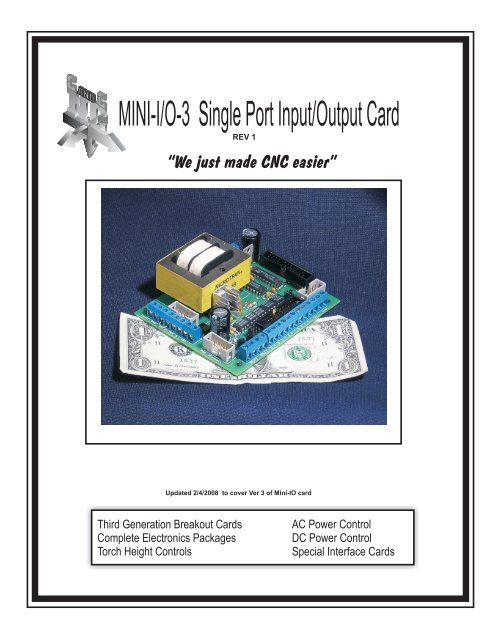
MINI-I/O-3 Single Port Input/Output Card - CandCNC
MINI-I/O-3 Single Port Input/Output Card - CandCNC
MINI-I/O-3 Single Port Input/Output Card - CandCNC
Create successful ePaper yourself
Turn your PDF publications into a flip-book with our unique Google optimized e-Paper software.
DB25 Connector to PC parallel portINPUT PinsOUTPUT Jacks4.280"Scale 1” = 1”4 Out 32 Out 1D A SD Z SD Y SD X SPC+5vPCGND1 Out1 J112 X step J43. X Dir J44. Y Step J55. Y Dir J56. Z Step J67. Z Dir J68. A Step J79. A Dir J710. Estop J111. X Limit/Home J812. Y Limit/Home J813. Z Limit/Home J914. Out 2 J1115. A Limit/Home J916. Out3 J1217. Out4 Charge pump J1218-25 PC gnd. NCSee pages on outputs to useQut1, 2, 3 or 4Feature Connector forSTEP & DIRECTION PCB0.152"3.125"J16 PCGND for Common To All drivesPCGNDPPORT IN14J3J2 +5 for Common To All drives21C210.330"PC+5vP<strong>Port</strong> INS&D MonitorC5SIP1J4 X Axis (S = Step; D= Dir)J16Q3R5R4U3109CJ13 AC INL1FLT 5VD X SU3L2J5 Y Axis (S&D)AXIS I/OD1JP11 23 4ISO4Q4 CPCREG3+F1D Y SJ2~21JP4J6 Z Axis (S&D)U2D4D Z SJP3J4~-J7 A Axis (S&D)D A SRPK2ISO5AXIS I/OR12D5J53.550"J11 OpenCollector out 1 and 2 (300ma max)2 Out 1ISO2C9J12 Buffered out 3 and *4 (20ma max)4 Out 3J6ISO3T2REG2*(note <strong>Output</strong> 4 shows Charge Pump activity)if option installed26J725PIN14OPTIONISO1PC 5VJ11Q1J20+~D3Q2J12~-C3J14RELAYCARD110109J1J109INPUTSJ8J9INPUTS21PWR XConnect2 14 3EstopFLT GND3.610"PPORT IN211C2P<strong>Port</strong> INJ16S&D MonitorSIP1AXIS I/OD1JP11 2Q3C3 4ISO4Q4 CPR5CR4U3109U3J221U2J4J5AXIS I/ORPK2R12D5C9J6 J7 J11Q1 Q22625PIN14OPTIONISO5 ISO2 ISO3 ISO1REG2PC 5VJ20+~D3J12~-C3J1410291INPUTSJ8J9PWR XConnect2 14 3INPUTSINTERCONNECT TOPORT2 EXPANSIONCARDIsolated <strong>Input</strong> 1Isolated <strong>Input</strong> 2Isolated <strong>Input</strong> 3Isolated <strong>Input</strong> 4These <strong>Input</strong>s areavailable on theOptional RemoteRelay <strong>Card</strong>. Do notuse these terminalsAnd the XYZA andE-stop on the RR2<strong>Card</strong>.14J311C5FLT 5VJ13 AC INREG3+F1~JP4D4JP3~-T211J1J10RELAYCARDINPUTSEstopFLT GNDJ1 E-Stop input (isolated)J10 Floating Ground for Isolated <strong>Input</strong>sL1L2 L2Mini I/O Breakout <strong>Card</strong> ConnectionsAC (95 - 125VAC 60HZ <strong>Single</strong> phase ONLY)220VAC 50HZ model available as optionUsed with Remote Relay <strong>Card</strong>RR2.For 220-240 VAC 50/60 HZ order International Power Upgrade
OPTIONAL REMOTE RELAY CARD CONNECTION4Out3J16J22 Out 1J4D A SJ5D Z SJ6D Y SJ7D X SPC+5vPCGNDJ11J121PPORT INJ31J15S&D MonitorRPK1C5U3AC INJ1310FLT 5VJP1 AXIS I/O1 23 4CPISO4-F11U2JP4J17D4JP3ISO5ISO225RPK2J20PIN14OPTIONISO3 ISO1PC 5VREG2T2Q1Q21RELAYCARD10J141XJ8YZJ9AJ10 J1PWR XConnectINPUTSIf the Relay <strong>Card</strong> header (orange) is usedwith the Remote Relay <strong>Card</strong> DO NOT USEJ1, J8,J9 or J10 on the <strong>MINI</strong>-IO-2 card.Those inputs are access via the QuickConnect Terminals (yellow) on theRemote Relay <strong>Card</strong>.Remote relay card can be connected viaa DB9 cable or if the Relay <strong>Card</strong> is in thesame location as the Mini-IO it can beconnected with a straight 10 pin (IDC)ribbon cable.L1L2Note: When using Remote Relay<strong>Card</strong> RR2 Out1 turns on large relay (K2)and Out2 turns on smaller relay (K4)Plug into standard 110 outlet12VDC Wall PlugPower Supply<strong>MINI</strong> IO REMOTE RELAY CARD(With Home switch inputs)Mount Remote Relay <strong>Card</strong>Using insulated (Nylon)Standoffs or insulated caseCommon (wiper)30A RelayNormally Open(NO) 30A RelayNote wiring polarity+12VDC INPC GNDJ25J24J23NCCOM NO10ARelayK4J2 COM J3K230A RelayNOUse shorting jumper orNormally closed Switchfor local e-stopJ18 J12EPO-2 EPO-1J1AZYX<strong>CandCNC</strong>J13J15J16J17HomesAJ20ZJ19YJ21XJ22<strong>MINI</strong>-IO INPUTRELAY CARDREV0These <strong>Input</strong>s arealso available on theMini-IO <strong>Card</strong>. Do notuse these terminalsAnd the XYZA andE-stop screw terminalson the Mini-IO card.XHomeDB9 Male ConnectorBack to Mini IO 9 PinAdapter <strong>Card</strong>CNOTypical Home Switch Connection
Normally closed contactsFor far limits. Wired in seriesC NC C NC C NCHome and limit switch hook upsCNOXHomeIsolated <strong>Input</strong> 1Isolated <strong>Input</strong> 2Isolated <strong>Input</strong> 3Isolated <strong>Input</strong> 4J1 E-Stop input (isolated)CNOCZHomeNOYHomeGNDJ10EstopJ1J9 J8Jumper for operationJumper can be replaced with aNormally Closed safety switchJ10 Floating Ground for Isolated <strong>Input</strong>sNOTE: If you use the remote Relay <strong>Card</strong> for Switch <strong>Input</strong>sDO NOT USE J1, J8, J9 and J10. Hook the switches to the samesignals on the Remote Relay <strong>Card</strong>.
J20 Option jumper determines the function of pin 14 on theAXIS IO Header. There are the possible settings. To changeA setting move the jumper to the designated position.If you are not using the Axis IO Header for direct connectionto a Xylotex card or for interface toan AXIS I/O <strong>Card</strong> then disregard this jumper setting4 Out 32 Out 1D A SD Z SD Y SD X SPC+5vPCGNDPPORT IN14J321C21P<strong>Port</strong> INS&D MonitorC5SIP1J16Q3R4U3109CJ13 AC INL1R5FLT 5VU3L2AXIS I/OREG3F1J2D1JP11 23 4ISO4Q4 CPC+~21JP4U2D4JP3J4~-RPK2ISO5AXIS I/OR12For Use with Xylotex direct connect use DefaultSetting. (Pin 14 not used)For use with AXIS I/O <strong>Card</strong> and drives that useCommon +5 (Gecko 201 and 3XX series) use +5to Pin 14 setting (A)D5J5For use with AXIS I/O <strong>Card</strong> and drives that useCommon GND (Gecko 203 and others)use PCGNDon pin 14 setting (B)ISO2On some control cabinets that use a DB25 and typicalParallel port interface pin 14 is used to turn on a relayThe <strong>MINI</strong>-IO has two open collector outputs (1 & 2) thatcan be used to turn on a relay using coil voltage from5 to 25VDC. Setting C maps the <strong>Output</strong> 1 pin to pin 14on the AXIS I/O header (and a DB25 attached to it). DONOT USE this setting and a Remote Relay <strong>Card</strong> together.Contact us for help using this with other control boxes.C9J6ISO3T226REG2J725PIN14OPTIONISO1PC 5VJ11Q1J20+~D3Q2J12~-C3J14RELAYCARD110109J1J109INPUTSJ8J9INPUTS21PWR XConnect2 14 3EstopFLT GNDABCJ20+5 on Pin 14DEFAULT1J20PCGND on Pin 141<strong>Output</strong> 1 on Pin14J201No Jumpers1
219211J2 +5 for Common To All drivesJ4 X Axis (S = Step; D= Dir)J5 Y Axis (S&D)J6 Z Axis (S&D)J7 A Axis (S&D)J11 Buffered out 1 and 2 (20ma max)J12 Buffered out 3 and *4 (20ma max)Mini I/O Breakout <strong>Card</strong> ConnectionsFor a Quick and Easy 3 or 4 axis build see Page 11 and 12Typical Step and Direction hookups for Gecko tyoe drivesOther connections not shownOut 4Out 3Out 2Out 1Feature Connector forSTEP & DIRECTION PCB4 Out 32 Out 1D A SD Z SD Y SD X SPC+5vPCGNDJ12J11J7J6J5J4J2J16Q2Q1PWR XConnectJ1426910AXIS I/OAXIS I/O10S&D Monitor25J20PIN14OPTIONRPK2C3D1C2 JP11 2SIP1Q3ISO1C12ISO2 ISO3ISO4 ISO53 4Q4 CPCR5R4INPUTS~+PC 5VU3R12PPORT IND52 1J8-~C9U2U3D3PPORT INREG24 3J9P<strong>Port</strong> INEstopJ3J3J1T2REG314~+C5FLT GNDD4FLT 5VJ101RELAYCARD-~AC INJ13INPUTSF1JP3JP4L1 L2NOTE: GECKO 203V Drives use Common GND instead ofCommon +5. Use J16 to Common on those drivesSet STEP polarity in software as POS (+) [red x in MACH]INPUT Signals OUTPUT JacksP-<strong>Port</strong> Pins See drawing1 Out1 J112 X step J43. X Dir J44. Y Step J55. Y Dir J56. Z Step J67. Z Dir J68. A Step J79. A Dir J710. Estop J111. X Limit/Home J812. Y Limit/Home J8DB25 Connector to PC parallel port13. Z Limit/Home J914. Out 2 J1115. A Limit/Home J916. Out3 J1217. Out4 Charge pump J1218-25 PC gnd. NCNote: When using Remote Relay<strong>Card</strong> RR2 Out1 turns on large relayand Out2 turns on smaller relay
DB25 Connector to PC parallel port<strong>MINI</strong>-I/O to Xylotex interface.XYLOTEX 3 or 4 Motor Driver <strong>Card</strong>See Xylotex instruction manualfor motor and power hookupsOPTIONSOther port pins not usedAuxillary Interface CableOrder Auxillary Cable from<strong>CandCNC</strong> part # CA-25-25J12 J11J7 J6 J5 J4 J2J16Out2&3Out1&2D A SD Z SD Y SD X S+5vPCGND21109212625J14109J151 2JP13 4J1721U1U2REG2J9 J8IN1&2IN3&4REG3T1J1J10EstopGNDJ13F1L1 L2
DB25 Connector to PC parallel port<strong>MINI</strong>-I/O to Xylotex/or other externalcontrol cabinetOPTIONSIDC header to DB25 adapter(comes with Xylotex boards)Also interconnects to <strong>CandCNC</strong> MTA100 <strong>Card</strong>See next pageDB25 to DB25 Extension Cableof appropriate lengthAuxillary Interface CableOrder Auxillary Cable from<strong>CandCNC</strong> part # CA-25-DB25FJ12 J11J7 J6 J5 J4 J2J16Out2&3Out1&2D A SD Z SD Y SD X S+5vPCGND21109212625J14109J151 2JP13 4J1721U1U2REG2J9 J8IN1&2IN3&4J13REG3T1J1J10EstopGNDF1L1 L2
1219212199219Quick and Easy 3 or 4 axisControllerPC withMACH3MTA100 Mass Termination AdapterParallel <strong>Port</strong>DB25
Connecting External Relays (Conventional)For units not using Remote Relay <strong>Card</strong> (RR2)12VDC Return (Gnd)+12VDCOut1 or Out2 can be used as shown.The +12VDC must be supplied from an externalsource if 12V coil relays are used. 24VDC relays canbe used but the +12VDC will need to be +24VDC(AC relays will NOT work). The minus side of eithersupply is connected to PCGND as shown. Do notConnect conventional relays to Out3 or 4.J11J7J6J5J4J2D A SD Z SD Y SD X S+5vJ7J6J5J4J2D A SD Z SD Y SD X S+5vQ1EQ2CEJ12CJ1410976J16PCGNDJ16PCGNDOut 1Out2Out 3Out 475J1521109J17212625Q1EJ11Q2CEJ12CJ1410921J141 14J3JP11 2RPK23 421J14RPK1C11U2D5T1REG2J10 J1 J9 J8GND Estop IN3&4 IN1&2
DB25 Connector to PC parallel port<strong>MINI</strong>-IO-3 Units Have an integral Charge Pump safety Circuit.If you are using control software other that MACH thatdoes not have the Charge Pump (Watchdog) option youWill need to remove the Charge Pump Enable Across pin 3and 4 and place a jumper Across pin 1 and 2 on JP1.The outputs will be inactive without the jumper or a working Charge Pump.CP1324PPORT IN21C2P<strong>Port</strong> INPCGNDJ16S&D MonitorU3109CPU3PC+5vAXIS I/OD1JP11 23J2Q4214CISO4U2D X SJ4RPK2ISO5D Y SAXIS I/OR12D5J5ISO2C9D Z SJ6ISO3REG2D A S26J725PIN14OPTIONISO1PC 5V2 Out 1J11Q1J20+~D3Q24 Out 3J12~-C3J14101099INPUTSJ8J921PWR XConnect2 14 31NCP214J31C5FLT 5VJ13 AC INL1 L2REG3+F1~JP4D4JP3~-T2RELAYCARD1J1EstopJ10FLT GNDINPUTS34Charge pump bypassA note about output 4: when using the Charge pump in MACH output 4 cannot be used forother signals. The output 4 pin will go high when the Charge Pump signal is present andis buffered and can be used to light an indicator or to turn on a relay to control the DCpower supply. If you do not use the charge pump <strong>Output</strong> 4 can be used to turn on other circuitsbut pin mappings need to be changed in the software
External Solid State Relay uisng on-board +5 supplyRequires SSR with 3-30VDC activation voltageAC INAC Rated SSR+-SSR can also be driven fromOut 3 or 4J7J6J5J4J2Out2&3Out1&2D A SD Z SD Y SD X S+5vJ7J6J5J4J2D A SD Z SD Y SD X S+5vQ1EJ11Q2CEJ12CJ1410976J16PCGNDJ16PCGND<strong>Output</strong> 1<strong>Output</strong> 2<strong>Output</strong> 3<strong>Output</strong> 475J1521109J17212625Q1EJ11Q2CEJ12CJ1410921J141 14J3JP11 2RPK23 421J14RPK1C11U2D5T1REG2J10 J1 J9 J8GND Estop IN3&4 IN1&2
Using outputs 3 and 4<strong>Output</strong>s 3 and 4 are buffered outputs that can be used to activate an 5 V TTL logic device OR as a Fifth Axis Stepand Direction output. The outputs are not available on the Expansion Header or the RR-2 Remote Relay <strong>Card</strong>. If youwant to use them you must make attachment to the terminals on J12. They are controlled by pins 16 and 17 on port 1NOTE: You cannot use output 4 AND the Charge pump circuit. You must disable the Charge pump in MACH3 andperform the CP bypass on J1 (jumper pins 1- 2).These outputs are NOT design to run high current loads (relays) or any voltage above 5V DC.J7J6J5D A SD Z SD Y SD X S+5vJ11J12J4J2J7J6J5J4J2D A SD Z SD Y SD X S+5vQ1EQ2CECJ1410976J16PCGNDJ16PCGNDOut 1Out2Out 3Out 475J1521109J17212625Q1EJ11Q2CEJ12CJ1410921J141 14J3JP11 2RPK23 421J14RPK1C11U2D5T1REG2J10 J1 J9 J8GND Estop IN3&4 IN1&2


