DTHCII user manual - CandCNC
DTHCII user manual - CandCNC
DTHCII user manual - CandCNC
- No tags were found...

You also want an ePaper? Increase the reach of your titles
YUMPU automatically turns print PDFs into web optimized ePapers that Google loves.
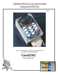
Block diagram of a typical DTHC II Hookupfor a system with full Automation Interfaceincluding Divided Arc Volts)DCP-01(option)for ARC OKused for ARC CurrentReadout; NOT RequiredDTHC IIModuleCat5 UTP cableUP to 25 ftLocated in the controlbox with the UBOB IIIcardTHC SENSOR PWMPlasma Pickup ModuleLocated external andclose to the Plasma cutterMIC-01 Custom CableCPC Plugom PlasmaUnitSingle cableHookup toPlasma Unit<strong>CandCNC</strong>Page 5
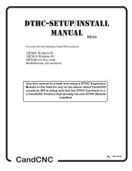
BASIC DTHC II Module Kit includes:FIRMWARE REV Number StickerTHC SENSOR PWMDTHC II ExpansionModule16 Pin IDC ribboncable to UBOB IIICAT5 UTP Cable25 ft<strong>CandCNC</strong>Page 6
modules setupdthcii mODULEthc sensor pwm modulerav-O1 vOLTAGE dIVIDER (option)THE FOLLOWING SECTIONS DEAL WITH SETTING UP EACH MODULE.IF YOU HAVE A <strong>CandCNC</strong> Product you may not need to use one or moreof these sections since some products have theses modules alreadyinstalled, tested and calibrated.IF you have a BLADERUNNER AIO Dragon -Cut or any MP3000-<strong>DTHCII</strong>based product (Plazpaks) than YOU CAN SKIP THE SECTION ONINSTALLING AND SETTING UP THE <strong>DTHCII</strong> Module,YOU DO NOT NEED TO ADJUST or Calibrate a <strong>DTHCII</strong> From thefactory. All units are calibrated prior to shipping<strong>CandCNC</strong>Page 7
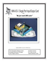
DTHC II EXPANION MODULE. Locatedabove the UBOB III card in most <strong>CandCNC</strong>products.. Ribbon cable connecting DTHCdown to UBOB card may cover adjustmentpots. If so, gently move it out out the way.Do not unplug the ribbon cable or the cardwill be disabled.Green Power LEDShould be ON16 pin header (plug)for DTHC to UBOBCableUsing the diagram below and with theTHC SENSOR PWM module in theTEST/CAL mode (LED flashing) adjusttheTorch Volts calibration pot whilewatching the TORCH VOLTS DRO in theMACH screen. Adjust the pot until thevalue displayed is 126 Volts. Note: onlyadjust the setting if it is not displaying 126to 127 voltsDTHC Self TestLEDRJ45 connector for cable toTHC SENSOR CARDBladeRunners and MP3000_<strong>DTHCII</strong>Units have this module alreadyinstalled and IT IS CALIBRATED. DONOT PERFORM THIS STEP ON THOSEUNITSFirmwareRevisionnumberDCP CalibrationPOT ADJUST perthe instructionsTORCH VOLTS CalibrationSET FOR 126VDCINDICATED [TORCH VOLTS]Unit is calibrated at thefactory.<strong>CandCNC</strong>Page 8
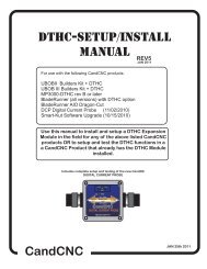
The photo shows a top view of the DTHC module card. There are two connections tomake. The first is the 16 pin IDC cable between the DTHC and the UBOB FeatureConnector. It’s the only 16 pin header on the UBOB. Both headers are keyed so thecable only fits one way. The other connection is to the DB9 socket from the THCSensor Card.Test LEDTest Button16 PIN HeaderPlug to UBOBUnits are calibratedat the factory.RJ45 Socket for interfaceto THC Sensor PWM CardActual card layoutmay vary from thephoto.Skip ths section for products thathave the DTHC II installed at theFactoryDC Power LEDINSTALLING THE DTHC INTO AN EXISTING MP3000 or BladeRunnerPRODUCT1. Locate the UBOB III card in the unit. It is the card with the PORT1 and SerialPort inputs. There is a 16 pin FEATURE CONNECTOR. Use the short 16 pin IDCcable included with the DTHC II and plug one end into the FEATURECONNECTOR2. Mount the DTHC II to the Front Panel using the 4-40 screws and L brackets onthe PCB. Line up the holes for the TEST LED and the TEST BUTTON. Replacethe 4-40 screws through the front into the L Brackets and tighten until the board issnug against the inside of the panel.3. Hold the back of the DTHC II Module and insert the other end of the 16 pin IDCcable from the UBOB card FEATURE CONNECTOR Header.4. Proceed to DTHC preliminary testing<strong>CandCNC</strong>Page 9
SKIP THIS SECTION IF YOU HAVE THE BladeRunner AIO Dragon-Cutor MP3000-DTHC with the <strong>DTHCII</strong> already installed at the factory.PRELIMINARY TESTING THE DTHC MODULE:Once you have installed the <strong>DTHCII</strong> module, power up the MP3000-<strong>DTHCII</strong> (or Plazpak orBladeRunner) and using a small probe (stiff wire, paperclip, etc push the TEST Button that isrecessed behind the front panel. Press and release one time. The yellow LED should start toflash. If it does not check the AC cord (main power) and the 16 pin ribbon cable to the UBOB IIIcard and plug and try again. There is a green LED on the DTHC II module that will light whenthe DC to DC converter is on. There are also three power LED’s on the UBOB card itself thatshould be on. If the Test LED lights and flashes it indicates that the DTHC II has power and theon-board processor is working. IT DOES NOT TEST ANY OTHER FUNCTION AT THIS POINT.Further testing requires you have MACH3 installed, the serial cable attached and theMP3000-DHTC profile and screen set loaded. See the section on Loading DTHC DRIVERSTHIS INSTALL IS NORMALLY DONE IN BladeRunner or MP3000SETUP PHASE (Separate Manual)LOADING DTHC DRIVERS/PLUG-INSThe Following assumes that MACH3 has been installed and that you can start MACH andget a default screen. While the MACH license does not need to be installed to load the<strong>CandCNC</strong> drivers, you cannot use the THC functions in MACH with a DEMO license. Referto the MP3000 or BladeRunner <strong>manual</strong> to install a license. . If you are building up a unit(UBOB or UBOB Builders Kit) you need to refer to those <strong>manual</strong>s for the base setup. If you havealready loaded the <strong>CandCNC</strong> support files (auto installer from the CD) then you can skip step 1below. The communication drivers need to be configured for DTHC II interface. The followingsteps will take you through setting up the system to use with the DTHC II module. 1. From the Support CD (or a web download locate the MP3000E-DTHC-UBOBIII_INSTALL file.Run it in Windows with MACH3 NOT RUNNING. It will place two MP3000-DTHC (or BladeRunner)icons on the desktop that will Start MACH with the correct profile instead of having to use MACHLoader each time, All of the plug-ins , MACH profiles and Icons to use with the DTHC II will beloaded during the install . The MP3000-DTHC profile in MACH will be added along with thematching screen sets and macros.2. After the MP3000-DTHC Install, open MACH3 using either the MP3000-DTHC Icon ORBladerunner AIO icon from the matching named profile in the MACH Loader.3. If you re-install MACH or upgrade, you may need to run the Install again.4. Open MACH using the MP3000-DTHC-UBOBIII or BladeRunner AIO profile (for the productyou have) and select CONFIG PLUGINS from the CONFIG menu in the top row. You will see alist of plugins that are available At the top of the list are the two <strong>CandCNC</strong> plug-ins. Each onestarts with “ccc_”5. Confirm that they are all ENABLED. If you make any changes make sure you close andrestart MACH.<strong>CandCNC</strong>Page 10
Defines COM (serial) Port<strong>DTHCII</strong> uses to talk to MACHFor all ESPIIBased UnitsNOTE: This screen mayvary if you have a unitwith the new HyT=Connect drivers installed.This a a confirmation andis part of the BladeRunneror MP3000 InsrtallpackageUse the screen to select the hardware you are using. The Ubob THC Plugin should beselected. If you have a ESPII Power supply (part of all BladeRunner, RouterPak andPlazPak products) then be sure to check UACM Modular Power Supply as well. Note theCOM port selection box. In most circumstances that will stay on “1”.This ends the section on doing an upgrade or installing a <strong>DTHCII</strong> into an MP3000 basic (router) control or aRouterPak or Bladerunner without the DTHC from the factory<strong>CandCNC</strong>Page 11
THC SENSOR PWM setupThe following section is to beused AFTER you have done thesetup and tests in the MP3000or Bladerunner User <strong>manual</strong>and have the <strong>DTHCII</strong> installedIn most circumstances the <strong>DTHCII</strong> is installed at the factory andtested and the THC SENSOR PWM is tested an calibrated. All basesoftware and drivers have been installed.<strong>CandCNC</strong>Page
IMPORTANT!This DRO should show100 when UP LED isflashing and 150 whenDOWN LED is flashingDYNAMIC SELF-TEST of <strong>DTHCII</strong> MODULE Activate the recessed TEST Button on the front panel of theMP3000-DTHC or your unit with the DTHC module installedand connected. The TEST LED should start flashing.The unitgoes into a test sequence where the TORCH VOLTS DRO isset to 100 and the UP screen LED flashes 3 times. Then theTORCH VOLTS DRO is set to 150 and the DOWN LED flashes3 times. This test sequence repeats until you hit the TestButton again and the TEST LED stops flashing.Make Sure MACH isOut of RESET beforeTestingThese three LED’s willflash 3 times andseqence between UPand DOWNNOTE DTHC ONLINE SHOWS IF MACH IS TALKING TO THE <strong>DTHCII</strong> MODULE If it is NOTon you DO NOT have serial communicatiuons between the PC and the UBOB III cardThe <strong>DTHCII</strong> module uses two separate communication paths to talk to MACH3. The SERIAL paththrough the COM port on the PC passes screen values (like Torch Volts and Torch Amps) and allowsviewing and loading CUT Profiles and Stored Settings to the <strong>DTHCII</strong> module. The <strong>DTHCII</strong> modulehas it’s own memory of settings and uses those until new settings are uploaded. With no serialcommunication new settings will not be used. If the test Torch Volts do not show the above VOLTAGE results the most probable cause isthe serial communications is not working between the PC and the MP3000/BladeRunner. Makesure you have the right COM port selected. All Standard cables supplied from <strong>CandCNC</strong> are straightthrough with all pins connected (sometimes called “extension cables) The Input Testing *BlsdeRunner User Manual Chapter G) should indicate if the inputs are workingcorrectly for the UP, DOWN and ARC OK. If any of the these three inputs do not flash during the testit means the PARALLEL PORT input is not working or MACH does not see it changing. Go back toyour install <strong>manual</strong> for the BladeRunner or MP3000 (separate <strong>manual</strong>) to troubleshoot the cause<strong>CandCNC</strong>Page
11TESTTHC SENSOR PWM SETUP AND TESTINGThe THC SENSOR PWM is designed to mount at the plasma cutter. It takes allof the signals from/to the plasma cutter and converts them to digital signals fornoise immunity . It is used with all of the Connection Kits all all types of plasmacutters. Mount the THC SENSOR close to the plasma cutter. DO NOT spliceor extend any of the cables (especially the divided volts cable)TORCH ARCONOKTEST+5V+12VRJ45 (Cat5) cable to<strong>DTHCII</strong> ModuleTORCHSWITCHon PlasmaARC OKFromPlasmaDCPTO<strong>DTHCII</strong>IIModuleDCP<strong>CandCNC</strong> THC SENSOR Plasma PWMPICKUP Plasma Pickup MODULE Modulefor DTHC for II DTHC SYSTEMS IIUSE CAT5 UTPCABLEARC VOLTSremove back cover foraccess to test buttonsTESTCANDCNCCALModelDIVIDED ARCVOLTS INMAX VOLTS36VDCAdvancedPWMTechnologyDivided volts from<strong>CandCNC</strong> Raw ArcVolts cardTO Plasma TORCHSWITCH or StartcircuitARC OK signal FROMPlasmaRED YEL RED GRN GRNTORCH-R ARCOK TEST +5 +12+5+12DCPTESTC14TO PLASMADCPJ3TorchSwitch1+U21ARCOKTORCH RELAYK1D1RAWVOLTSCALVR3InputVoltsARC OK1SCREWSJ2TO DTHC<strong>CandCNC</strong>THC Sensor PWMON/OFFARC OKRELAYREV 18ARC OKTRIPVR2TO PLASMA<strong>CandCNC</strong> THC SENSOR PWM Card(Inside Module)<strong>CandCNC</strong>Page12
THC SENSOR PWM FRONT PANEL LEDsTHC SENSORUnplugged orDTHC II poweris offTORCHARCOKTEST+5 +12NO ACTIVITYStandby stateTEST/CALMODE. TESTbutton is pushedand releasedTORCH FIREDfrom code orscreen buttonArc OK isActiveTEST LED FLASHES.Sends PWM signal toDTHC II. Calibrate <strong>DTHCII</strong> to read 126VDCSteady RED LED showsanytime Torch RELAY isactive on THC SENSORSTEADY YEL LED. Turnson if ARC OK from ARCOK TEST button is activeShows condition of power.Both must be ON whenplugged to DTHC II andpower is onReadout on TORCH VOLTS(screen DRO) confirms properoperation of THC SENSORPWM and DTHC LL inputConfirms Torch Relay onTHC SENSOR Card isactive. Tests signal fromDTHC II to fire TorchAlso Used to set sensitivity(trip point of ARC OK fromDCP. for hardware ARCOK from DCP(see Manual)Arc OK isActive, Torch isfiredTorch fire is active; ARC OKsignal from Plasma is activeShows proper operation ofthe ARC OK from theplasma (or using the DCPas the ARC OK)TORCH ARCON OKTEST+5V+12VTORCHSWITCHon PlasmaARC OKFromPlasmaTO DTHC IIModuleUSE CAT5 UTPCABLEDCPCANDCNCModelTHC SENSOR PWMPlasma Pickup Modulefor DTHC IIARC VOLTSremove back cover foraccess to test buttonsDIVIDED ARCVOLTS INMAX VOLTS36VDCAdvancedPWMTechnology<strong>CandCNC</strong>Page13
SCREWSD1TO PLASMA+J21VR3C14SETTING THE THC SENSOR PWM PRESCALEDIVIDER RATIOTHS MUST BE DONE TO MATCH YOUR INSTALLUNITS ARE SHIPPED TO MATCH THE RAV-01 (7:1)RATIO. USE THE CHART BELOW IF YOU ARE USINGTHE MODULE WITH A PLASMA WITH AN INTERNALVOLTAGE DIVIDER. SEE THE SECTION ONCONNECTING A PLASMA WITH AN INTERNALVOLTAGE DIVIDER TO DETERMINE TE PROPER RATIOTo set THC SENSOR PWM ratio divider option:1. Remove rear cover of THC SENSOR PWM Case2. determine the proper setting for the type setup you have.3. Set the small option jumper to match.VOLTSTESTCALVOLTSRAWVoltsSCALE20:116:17:1K1TORCH RELAYARC OKTEST50:1 = No jumperVoltsSCALE20:1VoltsSCALE20:1VoltsSCALEVoltsSCALE16:17:116:17:120:116:17:120:116:17:1or20:1 Scale (Hypertherm andsome others)16:1 Standard onThermal Dynamics, others7:1 Divider(from <strong>CandCNC</strong> RAV-01Card )VoltsSCALE20:116:17:150:1 Standard onHypertherm,Thermal Dyamics, othersBack of THC SENSOR PWMCover removedIMPORTANT:The Hypertherm 45 has aninternal voltage divider. Itcannot be changed for the50:1 ratio. Set your THCSENSOR PWM jumper tothe 50:1 position if you areusing the MIC-01 DirectConnect Cable<strong>CandCNC</strong>Page 14A
1THC SENSOR PWM MODULE TEST/CALTest LEDFlashes inTEST ModeTORCH ARCONOKTEST+5V+12VRJ45 (Cat5) cable to<strong>DTHCII</strong> ModuleTORCHSWITCHon PlasmaARC OKFromPlasmaTO DTHC IIModuleUSE CAT5 UTPCABLEDCPCANDCNCModelTHC SENSOR PWMPlasma Pickup Modulefor DTHC IIARC VOLTSremove back cover foraccess to test buttonsDIVIDED ARCVOLTS INMAX VOLTS36VDCAdvancedPWMTechnologyDivided volts from<strong>CandCNC</strong> Raw ArcVolts cardTHC SENSOR PWM (Plasma Pickup Module) can be put in TEST/CAL modewithout removing the card from the case. Turn the case over and remove the 4 corner screw holding the back on andcarefully pry off the back panel. It will expose the back of the PC board and thereare two small momentary pushbuttons and a dual row of option jumpers Theswitches are small tactile switchs that require light pressure. One push puts the unit in test/cal mode. The Test LED will flash. 126 to 127will display on the TORCH VOLTS DRO. A second push will take the unit out of test/cal mode and the LED will stopflashing and the TORCH VOLTS reading will return to Zero. Once in TEST mode you can calibrate the DTHC II module to display thecorrect TORCH VOLTS on the screen. See the <strong>DTHCII</strong> module section to in thefront part of this <strong>manual</strong> to find the calibration points. The THC SENSOR PWM isfactory calibrated. Do not try to set the calibration if the test voltage is MORETHAN A FEW VOLTS OFF THE TARGER OF 126. It will not fix problems withreading the torch volts or if it displays wrong when the torch is fired!The calibration is based on a simulated PWM from the circuit so if the prescaledivider setting is wrong the calibration will show correct but when the torch is firedthe voltage will be wrong.<strong>CandCNC</strong>Page 15
C14SCREWSVoltsU2TRIPOK ARCVR3D11DCPOKARCSwitchTorchJ3TO PLASMA+ON/OFF1ARC OKRELAYJ21Depress and release TESTbutton to test PWM circuitback to DTHC II. Test LEDon ( front) will flash and DTHCscreen in MACH shoulddisplay a voltage. Calibratedunits (see calibration section)should display 126 to 128volts durning test.Case not shown for clearity<strong>CandCNC</strong> THC SENSOR PWM CardTESTTO PLASMAInputCALVOLTSRAWVoltsSCALE7:120:150:1REV 18K1TORCH RELAYARC OKTESTSensor PWMTHC<strong>CandCNC</strong>TO DTHCCHECKING ARC OK SIGNAL BACK TO DTHC IICard:1. Remove case bottom.2 With RJ45 (UTP cable) connected to <strong>DTHCII</strong>and unit powered up, depress the ARC OK TESTBUTTON on the card. The ARC OK LED on theMACH screen should light. The ARC OK testLED on the front of the case will light.<strong>CandCNC</strong>Page16
THC SENSOR PWM MODULE TESTINGBefore you make connections to the plasma unit you may want to do some testingto confirm proper operation of the THC SENSOR PWM with the DTHC II Module.Connect the THC SENSOR PWM to the RJ45 (CAT5) connector on the DTHC IIModuleStart MACH3 using the Desktop Icon for DTHC Profile and make sure you cancome out of RESET and that the CP (Charge Pump) LED on the front of theUBOB/MP3000/BladeRunner is ON.On some products you may have to have the Motor DC on to come out ofRESETClick on the TORCH icon on the screen. You should see the LED above theTORCH button on MACH turn on and there will be a click in the THC Sensor PWM cardand the small LED on the front labeled TORCH ON will light. That indicates the TORCHON relay is working.The next check is to confirm the ARC OK circuit is working. Follow the instructionsfor the THC SENSOR PWM section and open the back and use the ARC OK Testbutton. The ARC OK LED on the MACH3 Screen should light. If it does you canproceed to the actual hookup of the THC SENSOR PWM Module to your plasma unit.If any of the tests fail make sure you have the cables firmly attached and thatthey are the correct type.All cards are checked at least twice and most three times before they leave the factory.It’s unusual for a THC SENSOR PWM to be bad or fail in no load testing. If you havechecked all of the connections, cables and MACH setup and you still cannot get the THCSENSOR to work contact us at 903-364-2740 or via e-mail at Tom @<strong>CandCNC</strong>.comNOTE: Some Larger (>100A) plasma units or older smaller models use various methodsto start the initial ARC. Most common is HF (HIgh Frequency) start. HF Start presentsseveral challenges. It uses the concept that higher frequency waves travel through air(and arc) easier than DC voltage. The HF is normally combined with a higher voltage andit starts an ARC that the plasma uses to ignite the air. Once the arc fires, if a conductivepart is close, the arc will transfer to the material. The HF start causes a lot of noise andcurrent spikes. The other form of High voltage start is the CD (Capacitor discharge)method. It is basically a high current version of an Automotive ignition system. Up to30,000 volts can be generated. If the THC Sensor is not protected, the high voltage andhigh frequency can cause component failure on the card or (worse) in the THC unit andeven burn the board. The THC Sensor PWM (REV18 and up) is protected from HF andmost High Voltage start circuits.<strong>CandCNC</strong>Page17
The smaller Hypertherm and other modern brand units use a low noise method called “blowbackarc start”. The electrode is mounted against a spring that keeps it pushed against the inside ofthe Nozzle as long as air is not flowing. When the unit is triggered the starts a few millisecondsafter the current starts to flow in the electrode circuit. As the air flows it pulls the electrode awayfrom the nozzle and creates an ARC. That is used to ionize the air and start the plasma.The DTHC II can be used with all types of plasma units. The HF units tend to be very noisy andsome even have large amounts of RFI. The total isolation of the DTHC II circuit from any lowlevel (PC logic) including any common ground, stops any conducted noise. The internal circuitsare protected from RFI with proper layout and careful attention to bypass components on allactive circuits.<strong>CandCNC</strong>Hooking Up Your Plasma Machine to the MP3000-DTHC/BladeRunnerAIO DTHC IICAUTION: Portions of this install may include opening your plasma cuttermachine and attaching wires. MAKE SURE THE UNIT IS UNPLUGGED PRIORTO REMOVING ANY COVER(S) OR MAKING ANY CONNECTIONS. Plasmaunits have HIGH VOLTAGES present that can be dangerous or lethal. IFYOU ARE NOT EXPERIENCED WORKING WITH HIGH VOLTAGES, DO NOTATTEMPT TO INSTALL THIS OR ANY OTHER DEVICE INSIDE YOURPLASMA UNIT YOURSELF. SEEK PROFESSIONAL HELP.In order to control your plasma unit, there are three main connections that needto be made to the plasma unit itself. All of the following operations are to bedone with the power disconnected from your plasma unitYou should determine which type install you will need for your plasma. There is a “decisionflowchart at the end of this <strong>manual</strong> that can help. It breaks down like this:There are 3 questions that need to be answered:1. ) Does your plasma unit have an internal ARC OK (dry contact) signal or one on a standardCPC connector?If not then you will need to purchase and install the Digital Current Probe Option (DCP-01)2.) Does your plasma unit have an internal voltage divider (Automation Interface) with a ratio of20:1 or 50:1 ?If not you will need to purchase and install the Raw Arc Volts divider card (RAV-01)3.) Are you using a hand torch or machine torch?If using a hand torch (even with a unit that is setup for automation you will probably need to tapinto the TORCH SWITCH wires from the hand torch to fire the torch remotely (from thecomputer). There is a page on how to do that from either the RAV-01 (if you already have itbecause of #2 above) or directly from the THC SENSOR PWM connector.If you have a Plasma unit that needs the RAV-01 card you will need to install that card in yourplasma unit or have it done. See the RAV-01 card section for instructions and warnings.If you are using the DCP-01 for ARC OK, there is an addendum at the end of this <strong>manual</strong> oninstalling and testing the DCP-01Page 18
1. Most plasma units have connection terminals where wires from the torch orpanel connectors attach to the internal PC Boards. The terminals provide aconvenient place to do your connections. Use crimp-on spade or roundterminals to attach the wires to the terminal strips. Make sure the new wires youinstall do not touch adjacent metal objects. On some machines there may bemore than one set of small wires and are used for sensing tip shorts and otherconditions. To identity the correct pair for the Torch Switch use an ohmmeteror continuity checker across each pair while you <strong>manual</strong>ly push the torch headbutton. When you identify the pair make note of where they attach. Use #22 to#18 stranded wire (twisted pair) to connect between the two screw terminals onthe THC Sensor PCB marked “Torch Switch” to the two switch terminals in theplasma unit.There is no polarity. NOTE: IF your unit has noise filter chokes from thetorch switch wires up to its internal logic card, it is recommended you placethe two wires to the RAV-01 PCB on the other side of the chokes fromtheir torch head connection (end closest to the internal logic card).2. If your unit has a tip voltage connection point (i.e. like the Hypertherm1000 series), you will need to use their <strong>manual</strong> and suggestions as to howto connect to the two points and run those wires to the RAV-01 card.Just make sure you use wire that has insulation rated for at least 400 V.Small signal wire like telephone wire (UTP) is not rated that high and canarc to nearby components. The RAV-01 card is designed to take thefull tip voltage and divide and filter it. Open circuit full tip voltage can beas high as 300VDC in some machines.3. does notIf your plasma unit have a designated tip voltagemeasurement point, you will need to locate a place inside the unit whereyou can get one wire onto the workclamp lead and another on the heavylead(s) that connects to the torch tip (electrode).a. Note: some machines like the Hypertherm 380 do not have a singleheavy wire to the Torch tip and instead have a set of parallel smallerwires that all terminate into one connector. In the case of the 380 theWHITE wires are the tip volts negative.b. You can identify both locations by visually tracing the two leads asthey come into the box. You should find several locations/terminalstrips that have connections to these two points and you can usethose for your sense wire connections. Use unshielded strandedtwisted wire of #22 to #18 ga rated for at least 400V insulation.<strong>CandCNC</strong>Page 19
c. Make a connection between the locations you have identified thattie directly to the two leads (workclamp and torch tip) to the two “TIPVolta” terminals. Make sure that these wires are routed where theycannot come into contact with hot or moving components. Starting with theREV 14 THC Sensor card the TIP VOLTS inputs have a polarity. The + side5.If you are using the <strong>CandCNC</strong> Digital Current Probe (DCP), you need not hookup any ARC OK signals to the RAV-01 card or the THC SENSOR PWM input. The ARCOK signal is derived from the TORCH AMPS (cut current) feedback. ARC OK trip pointis set in the CUT PROFILES in MACH3. See the section on installing and calibratingthe DCP-01/02 on how to set the ARC OK trip point.6.If you have a plasma unit that DOES have an Arc Good signal or you have theDCP module, DCP-01 unless you want the added features the DCP-01 can provide(see DCP-01 documentation) Just make the connection to the Arc OK terminals. Someunits provide only relaycontacts; (“dry Contacts”) For that type of signal the ARC OK inputs are J4 and J5 onthe THC Sensor card.Note: The term Arc Good is interchangeable with Arc Ok , Arc Xfer and OKto MOVE.7.NOTE: IT is ESSENTIAL that the chassis of the plasma unit have a goodearth ground. Refer to the suggested grounding section of the diagrams(#####) and provide for a good earth ground close to the table. A safetyground back to a breaker panel many feet away may be a good ground forAC frequencies (60hz) but poor for higher frequencies like plasma noise.Since we are bypassing any high frequency noise to the plasma chassis, ifit has a poor noise ground it can actually put noise back into the tip voltsrather than shunting it away!<strong>CandCNC</strong>Page 20
Own or Buying aPlasma unitfor CNC ?NOBetterGet one!YESIs it a HYPERTHERM45, 65 or 85 models ORTD A60/A80/A120?YESNODoes it have an ARC OKsignal.? (aka Arc TransferOK to Move, etc)Does it have the RearPanel CPC Connector?YESNOPurchaseOPTIONDCP-01YESNODoes it have the internalArc Voltage Divider?(Automation Interface PCB)CPC ConnectorInstalledYESNOPurchase ARC VoltageDivider Card OptionRAVD-01 CardPurchase AMIC-02CABLEPurchase AMIC-01CABLE<strong>CandCNC</strong>NO CPC ConnectorInstalledFINISHPage 21
DISCLAIMER AND LEGAL NOTICEThe following section covers the installation of a Voltage Divider card inside the plasma unit.There are dangerous and possibly lethal voltages present in a plasma power supply/unit.ALWAYS UNPLUG THE UNIT FROM THE AC POWER BEFORE REMOVING ANY COVERS.ALWAYS REPLACE ALL COVERS AND SAFETY BARRIERS BEFORE TURNING THEPOWER BACK ON.You do any install of a card inside of your Plasma Power Unit AT YOUR OWN RISK. If youdo not wish to do the procedure either find a person qualified to do so OR contact us foroptions.<strong>CandCNC</strong>/Fourhills Designs (hereafter referred to as “<strong>CandCNC</strong>”) nor any of itsresellers or agents will be responsible for any damage to any plasma unit or the loss ofany income resulting from using any of our electronics or using our instructions written orverbal to connect to any electronics. While we take care to provide accurate and conciseinformation, we will not be responsible for any damages to equipment, personnel, orsurrounding equipment, structures or land resulting from the direct or indirect use of ourproducts.The entire liability of <strong>CandCNC</strong> or any of its agents or employees is to replace orrepair products provided by <strong>CandCNC</strong>. Under no circumstances will we be liable for anydamages or loss exceeding the value of the actual products provided by us regardless if theproducts are used as described and in the proper manner. All <strong>CandCNC</strong> products carry awarranty that covers repair or replacement ONLY. Any labor, travel expense or costs toreplace a component or product outside the <strong>CandCNC</strong> factory is NOT COVERED bywarranty.If you do not accept the terms of this notice DO NOT OPEN OR INSTALL THERAV-01 CARD. Return the card for a full refund and seek an alternative way to sensethe voltage.CAUTION: Some plasma units use a very high voltage spark (Capacitor Dischargeor CD) arc starting system. While the RAV-01 card is protected from high voltage inputsCD type systems can cause arcing in the connecting wires or to nearby components.If you have a CD start unit and do not have experience working with high voltage systemsSEEK PROFESSIONAL HELP to do any install.<strong>CandCNC</strong>Page 22
TO WORKCLAMPCONNECTION (+)TO ELECTRODECONNECTION (-)<strong>CandCNC</strong> RAW ARC VOLTS Voltage divider card(CASE REMOVED)RAV- 01 OPTION KITFor Plasma Units WITHOUT Internal Voltage DividerJ15Tip VoltsWorkclamp+ [POS]CAUTION!HIGH VOLTAGEWHEN TORCH is ON- [NEG]Tip VoltsElectrodeJ14RAV-01 Raw Arc Volts CARDCAUTION: High Voltages PresentWhen TORCH is ON.D13CAUTION!HIGH VOLTAGECAUTION!HIGH VOLTAGEC1REV 18CAUTION: High Voltages PresentWhen TORCH is ON.R1<strong>CandCNC</strong>L2R6THCPLASMAPICKUPSW11MANUALSW31Volts4 3ARC OKARCOKOutVOUTTORCHCAUTIONFIRESTORCHLocal Connections+DividedVoltsTP1 -+ +-TP2FIRESW2DividedARC OKTORCH SWITCH2 1TORCH SWITCHSWITCH1-VoltsJ5SAC-01 Shieilded Cableto Torch Sensor PWMModuleTO THC SENSOR PWMMODULE use CCAB-311TO THC SENSOR PWMPlexglasInsulatorBase(safety shield)SHIELDED ANALOG CABLE48” MinPart# SAC-01ScotchLOCIDC Splices (RED)2 piecesRAV to THCSensorPWM Interconnect1PART # CCAB-3148" (min)1<strong>CandCNC</strong>Page 23
TO WORKCLAMPCONNECTION (+)TO ELECTRODECONNECTION (-)J15Tip VoltsWorkclamp+ [POS]CAUTION!HIGH VOLTAGEWHEN TORCH is ON- [NEG]Tip VoltsElectrodeJ14RAV-01 Raw Arc Volts CARDCAUTION: High Voltages PresentWhen TORCH is ON.D13CAUTION!HIGH VOLTAGER1CAUTION!HIGH VOLTAGEC1<strong>CandCNC</strong>REV 18CAUTION: High Voltages PresentWhen TORCH is ON.L2R6THCPLASMAPICKUPSW11MANUALSW31Volts4 3ARC OKARCOKIF YOU HAVE AN INTERNAL ARCOK SIGNAL: Connect one wire toTerminal 4 and Terminal 3 above(left two terminals)IF YOU DO NOT HAVE ANINTERNAL ARC OK SIGNAL: Youwill need to purchase a DCP-01Digital Current Probe. It plugsOutVOUTTORCHCAUTIONFIRESTORCHLocal Connections+DividedVoltsTP1 -+ +-TP2FIRESW2DividedARC OKTORCH SWITCH2 1TORCH SWITCHSWITCH1-VoltsJ5SAC-01 Shieilded Cableto Torch Sensor PWMModuleTO THC SENSOR PWMMODULE use CCAB-311TO THC SENSOR PWMTORCH SWITCH Terminals.If you have a plasma unit with a MachineTorch you will need to locate the twotorch fire connection points. in someunits it is called START. IT is a REMOTEFire set of wires.IF YOU HAVE A HAND TORCH you willneed to identify the two Torch Switchwires that come from the Hand torch andRAV-01 PREFACE: General InformationIMPORTANT: When making any connection inside thePlasma Unit, disconnect the unit from the AC Line(unplug it). Do not open the case with power on the ACline. THERE ARE DANGEROUS VOLTAGES present inthe unit anytime it is connected to an AC source EVEN IFThe RAV-01 can be used several ways so it can get confusing about makint the connections.The primary use of the RAV-01 is to take Raw Arc Volts (undivided votls and divide it by aprecise ratio so it can be used by the THC SENSOR PWM module to generate a digital signalto send volts data to the <strong>DTHCII</strong> Digital Torch Height Module. In some circumstances that is allthat you will use the card for. Examples are on the Hypertherm 1000/1250/1650 series and theThermal Dynamics “A” series. Both types have a rear CPC connector (14 pin) that has theTorch Fire and ARC OK signals available and are used with the <strong>CandCNC</strong> MIC-02 interfacecable/ So ONLY the Shielded Analog Cable (SAC-01) is used between the RAV-01 and THCSENSOR PWMOn other types of Plasma cutters that have no external connectors for ANY of the requiredsignals the RAV-01 can become a connection board for accessing those signals internally andpassing them to the THC SENSOR PWM Module via the CCAS-01 4 wire cable. The followingpages will cover how to first use the RAV-01 as a voltage divider card in a unit that does nothave an integrated voltage divider. If you have a plasma unit with no external connectors thanthe next section shows how to use the RAV-01 to fire the torch from the software. Finally ifyour plasma has an internal access to the Torch fire for a mechanical torch and an internal ARCOK (OK to MOVE). REMEMBER: the RAV-01 is just a pass-through (place to makeconnections) for ARC OK and TORCH FIRE. It does not sense or provide those signals.There are added pages on some Plasma Cutters and how to connect them; sometimes there ismore than one way. If there is a way to access the proper signals externally than that methodwith a cable is recommended. In each case the objective is to get the signals in and out of theTHC SENSOR PWM Module<strong>CandCNC</strong>Page
TO WORKCLAMPCONNECTION (+)TO ELECTRODECONNECTION (-)RAV-01 Mounted inside Plasma UNIT.<strong>CandCNC</strong> RAW ARC VOLTS Voltage divider cardJ15Tip VoltsWorkclamp+ [POS]CAUTION!HIGH VOLTAGEWHEN TORCH is ON- [NEG]Tip VoltsElectrodeJ14CAUTION: High Voltages PresentWhen TORCH is ON.D13CAUTION!HIGH VOLTAGECAUTION: High Voltages PresentWhen TORCH is ON.R1CAUTION!HIGH VOLTAGEC1<strong>CandCNC</strong>REV 18L2R6THCPLASMAPICKUP4SW113ARCOKVoltsOutVOUT2+DividedVoltsTP1 -+ +-TP2MANUAL TORCH FIRESW31Local ConnectionsTORCH SWITCHCAUTIONFIRESTORCHSW211ARC OKDividedARC OKTORCHSWITCH-TORCH SWITCHVoltsJ5SAC-01 Shieilded Cableto Torch Sensor PWMModuleTO THC SENSOR PWMMODULE use CCAB-311TO THC SENSOR PWMPlexiglasSafetyShield1TORCH ARCONOKTEST+5V+12VRJ45 (Cat5) cable to<strong>DTHCII</strong> Module11TORCHSWITCHon PlasmaARC OKFromPlasmaDCPTO<strong>DTHCII</strong>IIModuleDCP<strong>CandCNC</strong> THC SENSOR Plasma PWMPICKUP Plasma Pickup MODULE Modulefor DTHC for II DTHC SYSTEMS IIUSE CAT5 UTPCABLEARC VOLTSremove back cover forTESTCANDCNCCALModelDIVIDED ARCVOLTS INMAX VOLTS36VDCAdvancedPWMTechnologyaccess to test buttons<strong>CandCNC</strong> THC SENSOR PWM CardDivided volts from<strong>CandCNC</strong> Raw ArcVolts cardTHC SENSOR PWM MODULEMounted outside plasma unit<strong>CandCNC</strong>Page
Connecting a plasma with no internal voltage divider to aDTHC II using the Optional RAV-01 CardFor Plasma Units that have NO externalConnector for the required signals ORdo not have an internal voltage divederMounting the RAV-01 Card inside your unitThe mounting location for the card will vary from one type/brand of plasmaunit to another. Pick a location and mount the RAV-01 using the Plexiglass shieldusing small self tapping screws (not furnished) or adhesive Velcro strips. Mountthe card at least 1 inch away on all sides from any internal cards, terminals or barewires. The standoffs of the card are insulated and so the card can be mountedwith the plexiglass shield against the chassis. There is high voltage present whenthe torch fires at the end of the card where the RAW ARC VOLTS is connected.Keep that end of the card away from ANY conductive object closer than 2 inches.Once you have the RAV-01 Card mounted in a safe location you will needto make provisions to connect the two low voltage cables (CCAB-31 and SAC-01).You need to provide holes on the rear or side of the unit (BE CAREFUL DRILLINGMETAL IN YOUR UNIT. TINY SHAVINGS CAN FALL ON PARTS THAT COULDSHORT.) Ream the holes smooth or drill them oversized and use a rubbergrommet to protect the wires. Clean up with a magnet or blow the cabinet outwith air. One hole needs to be able to pass the diameter of the SAC-01 Plug. Theother needs to pass the diameter of the cable for the CCAB-31. NOTE: The4 wide plug on the CCAB-31 cable is removable. You will need to remove theend that passes into the enclosure to fish the wire through for the RAV-01 Connection.BE SURE TO FOLLOW THE COLOR CODE TO REATTACH THE CONNECTOR.THE COLORS ON BOTH ENDS WILL GO ONTO THE SAME TERMINAL/PINNUMBER. Connect the two cables where the diagram shows to the RAV-01 Card.Making the connectionsA WORD ABOUT ARC OK SIGNALS: “ARC OK” is our terminology of a signal coming backfrom the plasma unit that signals the unit has fired the torch and has a valid arc. Most plasmaunits made for <strong>manual</strong> cutting DO NOT HAVE an ARC OK (also known as ARC XFR;TRANSFER; OK to MOVE and other similar terms). It is a circuit that closes (relay contacts orsometimes called “dry contacts”) on a valid arc. Units that do have the signal will have itlabeled, on a connector or covered in their <strong>manual</strong>. IF YOU HAVE DOUBTS, assume the unitdoes NOT have ARC OK and follow the guidelines below.IF YOUR PLASMA HAS AN ARC OK CONNECTION POINT: There will be two connection points.Run a small gauge (18-24 ga) pair of wires from the internal ARC OK points to the two screwterminals on the edge of the RAV-01 Card. This wire carries no high voltage or current. Follow thediagram on Page ____. There is a board labeling program on some cards where the white printingis WRONG! USE THE PICTURES IN THIS MANUAL to make the connection. Make sure theconnection is secure and that no stray wires are outside the opening of the screw terminals.IF YOUR PLASMA DOES NOT HAVE AN ARC OK CONNECTION POINT: Turn to the section onthe DCP-01 Digital Current Probe option. You will need to purchase and install this option toprovide a reliable ARC OK signal to your <strong>DTHCII</strong> system.<strong>CandCNC</strong>Page 29
Connecting a plasma with no internal voltage divider to a<strong>DTHCII</strong> using the Optional RAV-01 CARDFinding the correct connections.The first signal you need to identify and locate is the Raw Arc Volts (Raw Tip Volts). This is thevoltage between the Electrode and the Workclamp. The Hypertherm 1000 thru 1650 series havetwo spade terminals (j15 and J16) that are for easy connection of Raw Arc Volts. On latermodels (45/65/85) WITHOUT the internal voltage divider the location of the Raw Arc Volts is notas obvious but they have Field Service Bulletins where they give detailed directions on findingthe Raw Arc Volts. Our <strong>manual</strong> covers connection to the PowerMax 1000, 1250 and 1650 aswall as the PowerMax 45 and PowerMax 65/85/105 with the optional CPC connector.https://www.hypertherm.com/Xnet/library.jsp/null is a search page where you can enter yourmodel number and then search the FSBs. The files are in PDF format.For other brands of plasma units or a model not designed to be automated the search forconnection points may be a little more difficult but not impossible. The key is the leads going tothe torch cable. On most plasma units you can locate these signals by opening the unit(POWER DISCONNECTED!) and visually tracing the wires coming from the plasma torch. TheWorkclamp will be connected to a stud or terminal inside and is pretty easy to identify. It is thePOSITIVE (+) side of the circuit. The Electrode side goes up the plasma cable to the torch head.It will be one heavy wire or a series of smaller gauge (12ga or larger) stranded wires of the samecolor and they will all connect to the same electrical spot (bus) inside the plasma. In a lot of unitsthese wires are all solid WHITE in color but do not use color as your clue. Some plasmamanufacturers provide block level schematics in their use or service <strong>manual</strong> that give wire colors(and in some cases terminal numbers and locations).WHEN YOU HAVE LOCATED THE WORKCLAMP AND ELECTRODE WIRES IN THE UNIT:Using a two conductor wire (18-22 ga) [not supplied] with insulation rated to 400V or more crimpon two ring or fork terminals. USE WIRES OF TWO DIFFERENT COLORS and longenough to reach the RAV-01 Card using an indirect route (give yourself extra wire). Run the firstcolor wire (red or the brightest color) to where the WORKCLAMP attaches. Normally that will bea heavy bus bar with other smaller wires attached. If it is a single large stud you will need a ringterminal that will fit over the stud. That will be your positive (+) wire.Use the other wire color and run a connection using a ring or fork terminal to where theELECTRODE wires attach.Carefully route both wires from their connection points over to where they will attach at spadeinputs on the edge of the RAV-01 Card. Keep the wires away from other high voltage wires orcomponents on the circuit board. Use nylon wire ties to secure the wires to other wire bundles orto the chassis. DO NOT WIRE TIE THEM TO COMPONENTS ON THE PC BOARDS. DO NOTUSE LOW VOLTAGE WIRES LIKE THOSE USED FOR WIRING PHONES OF NETWORKS.<strong>CandCNC</strong>Page 30
USING THE RAV-01 TO FIRE THE TORCH(for plasam units with no external connectorto fire the torch or with a hand torchThe next internal signal you need to locate is the TORCH SWITCH. If you are connecting to a unitwith a Hand Torch you will need to find and tap into the two wires coming from the torch switch in thehand piece. How will you know? First the wires will be smaller and different colorsthan the ELECTRODE or PILOT ARC (more about that later) wires. In most cases there will be foursmaller wires. Two will be the torch switch and two will be the PIP or CIP (Consummables-In-Place)wires. Once again the manufacturers documents can be of service here identifying colors and evenconnection points. If you do not have the manufacturers service information with schematics andcannot find them on-line you will need to do a little detective work to identify the torch switch wired.The first thing your should do is get an Ohmmeter, and with it set to low ohms. Short the leadstogether and make sure the meter shows the change and displays low (close to zero) ohms. If yourmeter has a “squaker” continuity tester position then use that as a tone indication. Clip across two ofthe four smaller wires. If you get no reading or tone (or an OV or OL indication) the circuit is open.Activate the torch switch on the hand piece and if the reading goes to a low value of ohms (
USING the RAV-01 to fire the Torch (unit has no external connectorto fire the torchNOTE : Some models of plasma cutters that have a CNC connector (CPCconnector) have a safety lockout to prevent firing the hand torch remotely. Thelisted connection will fire the torch the same as pulling the trigger. Both thetrigger and the software can fire the torch. There may be a way to bypass thelock-out and use the CPC connector to fire the torch. Contact us via e-mail forother possible solutions on plasma cutters that have a CPC connector.Use ScotchLoc IDC Splices (RED) to tie Torch Switch output on THC Sensor(J10) Screw Terminals. Locate Orange and Violet wires at J10 in thePowerMAX box and tap each wire as shown. To test short two screwterminals on J10 THC Sensor and torch should fire (Plasma Unit on)CONNECTING HAND TORCH TO THC SENSOR CARDWire colors will varyby brandConnect to Screwterminals J10 1 & 2 onthe THC Sensor CardFROM HAND TORCH CABLEIMPORTANT: When making any connection insidethe PowerMAX disconnect the unit from the ACLine (unplug it). Do not open the case with poweron the AC line. THERE ARE DANGEROUSVOLTAGES present in the unit anytime it is connectedto an AC source EVEN IF IT IS TURNED OFF.<strong>CandCNC</strong>PAGE 27
TO WORKCLAMPCONNECTION (+)TO ELECTRODECONNECTION (-)Using the RAV-01 to fire the torchJ15Tip VoltsWorkclamp+ [POS]CAUTION!HIGH VOLTAGEWHEN TORCH is ON- [NEG]Tip VoltsElectrodeJ14RAV-01 Raw Arc Volts CARDCAUTION: High Voltages PresentWhen TORCH is ON.D13CAUTION!HIGH VOLTAGER1CAUTION!HIGH VOLTAGEC1<strong>CandCNC</strong>REV 18CAUTION: High Voltages PresentWhen TORCH is ON.L2R6THCPLASMAPICKUP1SW1MANUALSW31VoltsCAUTIONFIRESTORCHDividedVolts4 3 2 1ARC OK TORCH SWITCHARCOK SWITCH+Divided VoltsOutTP1 -VOUT + +-TP2-TORCH FIREJ51 PART # CCAB-31SW2Local Connections1ARC OKTORCH SWITCHSAC-01 Shieilded Cableto Torch Sensor PWMModuleTO THC SENSOR PWMMODULE use CCAB-311TO THC SENSOR PWMConnection to THC SENSOR PWMModule1Torch Fire wiressee previous page forconnecting to Hand torchmodels without CPCconnectors
TO WORKCLAMPCONNECTION (+)TO ELECTRODECONNECTION (-)1J15Tip VoltsWorkclamp+ [POS]- [NEG]Tip VoltsElectrodeJ14CAUTION: High Voltages PresentWhen TORCH is ON.<strong>CandCNC</strong>CAUTION: High Voltages PresentWhen TORCH is ON.SW1SW3ARCOKSW2TORCHSWITCH+-J5SAC-01 Shieilded Cableto Torch Sensor PWMModuleTO THC SENSOR PWMMODULE use CCAB-311CONNECTING TO HAND TORCH SWTICHWIRES FROM RAV-01sWTICH WIRES FROMPLASMA HAND PIECEALTERNATE METHOD TO FIRE HAND TORCH IF NOTUSING RAV-01 CARDTORCH ARCON OKTEST+5V+12VRJ45 (Cat5) cable to<strong>DTHCII</strong> ModuleTORCHSWITCHon PlasmaARC OKFromPlasmaTO DTHC IIModuleUSE CAT5 UTPCABLEDCPTHC SENSOR PWMPlasma Pickup Modulefor DTHC IIARC VOLTSremove back cover foraccess to test buttonsCANDCNCModelDIVIDED ARCVOLTS INMAX VOLTS36VDCAdvancedPWMTechnologyDivided volts from<strong>CandCNC</strong> Raw ArcVolts card<strong>CandCNC</strong>Page
100 VDCor moreto WORKCLAMPconnection (+)RAW ARCVOLTS IN350 VDC (Max)To Electrode connection(-)<strong>CandCNC</strong> RAW ARC VOLTS (RAV-01) Voltage divider cardCAUTION: HIGH VOLTAGE PRESENTON CARD WHEN TORCH IS FIREDJ15Tip VoltsWorkclamp+ [POS]CAUTION!HIGH VOLTAGEWHEN TORCH is ON- [NEG]Tip VoltsElectrodeJ14D13CAUTION!HIGH VOLTAGER1CAUTION!HIGH VOLTAGEC1<strong>CandCNC</strong>REV 18L2R6THCPLASMAPICKUP1SW111SW3VoltsOutVOUTCAUTIONFIRESTORCH+Local ConnectionsARC OKDividedVoltsDividedTP1 -+ +-TP2MANUAL TORCH FIRESW21TORCH SWITCHIN-ARC OKTORCH SWITCHVoltsPUSH BOTH BOTTONS TOMANUALLY FIRE TORCHJ51Raw Volts PresentLEDTO THC SENSOR PWMRaw volts TESTBUTTONNOTE: PRINTINGONREV18PCBforTorchSwitchandArcOKareWRONG! Usethisdiagram<strong>CandCNC</strong>TESTING /TROUBLESHOOTING RAW ARC VOLTS CARD Make sure all of the connections to the ARC OK (if units has that signal) and the TORCHSwitch (START circuit) are connected according to the <strong>manual</strong>.To Test the Torch Firing circuit1. Turn on the plasma unit.2. Clear all persons away from torch.3. USE BOTH TORCH FIRE BUTTONS at the same time. Use an insulated pair ofprobes to activate the switches4. If torch fires it indicates the Torch Switch wires are connected correctly.5. If the plasma unit fails to fire and start the arc, then the connection is not correct, orthe unit has a safety lockout to prevent remote firing a hand torch. NOTE IF YOU ARE NOTFIRING THE TORCH THROUGH THE RAV-01 Card THAN THIS TEST WILLNOT FIRE THETORCH! If you are using the RAV-01 JUST for divided volts SKIP THIS TEST.To test the voltage divider circuit you MUST have passed the TORCH FIRING TESTabove.1, To test to see if the voltage divider circuit is working use the two TORCH FIREBUTTONS to fire the torch (or do it from MACH if you have that capability and depress the RAWVOLTS TEST BUTTON at the same time.2. The RAW VOLTS PRESENT LED should light. It indicates that Divided volts isreaching the divided volts cable.3. If it fails to light then check the RAW ARC VOLTS connections and their polarity. If theleads are reversed you will NOT get any divided volts and the LED will not light. Clip Meteracross TIP VOLTS terminals set on 200VDC and fire torch with TORCH FIRE BUTTONS(Caution high voltage). Reading should be between 130 to 180 VDC on plasma units (opencircuit voltage)NOTE: With the RAW VOLTS TEST Button active the TORCH VOLTS reading in MACH will notbe correct. The test loads the circuit. This is normal and it is used only to determine if the unitis getting and dividing the RAW ARC VOLTS.Page
J15Tip VoltsWorkclamp+ [POS]- [NEG]ElectrodeCAUTION: High Voltages PresentWhen TORCH is ON.CAUTION: High Voltages PresentWhen TORCH is ON.SW1SW3ARCOKSW2TORCHSWITCH+-J5HYPERTHERM 1000/1250/1650Connecting THC SENSOR PWM CARDFOR OPERATION WITH DTHC IIJ15J16+-TIP VOLTS CONNECTIONJ15 and J16 are Slide-on connectors located on the PCBUse 18 or 20ga insulated Hookup wireInsulation rating to 400V MinDAMGERHIGH VOLTAGEWHEN TORCHis ONTo TORCH -(ELECTRODE WIRES)J19 Located inside Cabinet on PC BoardBLKYELREDWHTinternalconnectionsARC XFRTO ELECTRODECONNECTION (-)J14Tip VoltsHIGHVOLTAGE CAUTION!<strong>CandCNC</strong>PLASMA THCPICKUPHIGHVOLTAGE CAUTION!WHENTORCHisONR6C1TO WORKCLAMPCONNECTION (+)D13HIGHVOLTAGE CAUTION!START SIGNALCAUTIONTORCH FIRESTORCHSWITCH ARCOKDivided Volts<strong>CandCNC</strong>TO THC SENSOR PWM 1MODULE TOTHCSENSORPWM use CCAB-31SAC-01 Shieilded Cableto Torch Sensor PWMModuleConnect to THC SENSOR PWM VIACCAB-31 CablePage 33
1TO WORKCLAMPCONNECTION (+)TO ELECTRODECONNECTION (-)HYPERTHERM 1000/1250/1650 andThermal Dynamics units withrear CPC connector and no Arc VoltageDividerRaw arc volts connection pointsvary from one model to anotherRefer to manufacturers <strong>manual</strong>sfor locations+-Use 18 or 20ga insulated Hookup wireInsulation rating to 400V MinJ15Tip VoltsWorkclamp+ [POS]CAUTION!HIGH VOLTAGEWHEN TORCH is ON- [NEG]Tip VoltsElectrodeJ14OPTIONAL RAV-01MOUNTED INSIDE PLASMACAUTION: High Voltages PresentWhen TORCH is ON.D13CAUTION!HIGH VOLTAGER1CAUTION!HIGH VOLTAGEC1<strong>CandCNC</strong>REV 18CAUTION: High Voltages PresentWhen TORCH is ON.L2R6THCPLASMAPICKUP1SW1MANUALSW31Volts4 3ARC OKARCOKCAUTIONFIRESTORCH+DividedVoltsDivided VoltsOutTP1 -VOUT + +-TP2-TORCH FIREJ5Local ConnectionsSW2ARC OKTORCH SWITCH2 1TORCH SWITCHSWITCH1SAC-01 Shieilded Cableto Torch Sensor PWMModuleTO THC SENSOR PWMMODULE use CCAB-311TO THC SENSOR PWMTO CPC CONNECT ON REAROF PLASMARoute shielded cablethrough rear bulkheadMETHOD TO CONNECT TO UNITWITH MACHINE TORCH USINGREAR CPC CONNECTOR FORTORCH FIRING AND ARC OKMIC-02For units with CPC but NOInternal Voltage DividerTORCH ARCON OKTEST+5V+12VRJ45 (Cat5) cable to<strong>DTHCII</strong> ModuleTORCHSWITCHon PlasmaARC OKFromPlasmaTO DTHC IIModuleUSE CAT5 UTPCABLEDCPCANDCNCModelTHC SENSOR PWMPlasma Pickup Modulefor DTHC IIARC VOLTSremove back cover foraccess to test buttonsDIVIDED ARCVOLTS INMAX VOLTS36VDCAdvancedPWMTechnologyDivided volts from<strong>CandCNC</strong> Raw ArcVolts cardTHC SENSOR PWM MODULE<strong>CandCNC</strong>Page 34
HYPERTHERM PowerMAX 45Connecting THC SENSOR CARDFOR OPERATION WITH MP3000-DTHC Iand BladeRunner Dragon-Cut seriesRAV-011 & 2ScrewTerm 3 & 4Drawign not to scaleLOCATION OF J19 and J21Inside PowerMAX 45FRONTJ19 or J18(white wire)TP 19WTP 18R192 VDC192 VDC+ -+ -TP 17BJ21 (work lead)CAUTION: Make sure wiresand terminals do not touchanything but the screws forJ19 and J21. HIGHVOLTAGE IS PRESENTWHEN TORCH IS ON.To RAV-01 J14NEG input terminal<strong>CandCNC</strong>To RAV-01 Card J15POS input terminalPage
THIS SECTION RESERVED FOR POWERMAX 65.85 HOOKUP DATA<strong>CandCNC</strong>Page
THERMAL DYNAMICSAutomated Cutmaster® 151CONTROL CABLE PIN - OUT DIAGRAM5 / Orange (Negative) Divided Arc Volts1 / BlackAlignmentSpline2 / White3 / Red / Torch Switch6 / Blue / (Positive)Divided Arc Voltser4 / Green / Torch Switch7 / Yellow / Arc Volts (Negative)AlignmentSplinesAlignmentSplines14 / White - Red / OK to Move8 / Logic Common12 / White - Black / OK to MoveUse <strong>CandCNC</strong> part # MIC-01APPENDIX 7: INTERFACE PCB SWITCH SETTINGS(MOST COMMON SETTINGS)<strong>CandCNC</strong>Automation Interface Switch Setting Chart -Common Voltage Divider Output SettingsVolts Out Volts OutSW 4 SW3 SW2 SW1Divisionfor forFactor1 2 3 4 5 6 7 8 100vdc In 200vdc In0 = DOWN = OFF, 1 = UP = ONFactory Default SettingsSuitable for Thermal Dynamics SC-11 Standoff Control:0 0 0 0 0 0 0 0 6.00 12.00 16.3:1Other Common Settings:0 0 0 1 0 1 1 0 5.00 10.00 20:10 1 0 1 0 0 0 1 3.3 6.6 30:11 1 0 0 0 0 0 0 2.5 5.0 40:11 1 1 1 1 1 1 1 2.0 4.0 50:10 = DOWN = OFF, 1 = UP = ONPreferred SettingMatch THC Sensor PWMsetting to thisPage 37
THERMAL DYNAMICSThermal DynamicsAUTOMATION INTERFACE PC BOARDSWITCH LOCATIONSArc Volts DividerSet SwtichesAutomation Interface PC Board<strong>CandCNC</strong>Page 38
L11TORCHPIP SWITCHTORCH SWITCHTHERMAL DYNAMICSATC CONNECTORJ1Q5/PIP/START24VAC RETURN24VAC SUPPLYOK-TO-MOVE+12VDCPILOT IGBT-V OUT 1ELECTRODE1TIP1WORK1J1012345678J91234567E64E35P1078798081828312345678CNC INTERFACE STANDARD ON A40 & A60 UNITSCNC INTERFACE OPTIONAL ON CM52 & CM82 UNITSJ21413121110987654321}}12345678-+12345678OK TO MOVE(5A @250VAC / 30VDC)/START / STOP(Sink 50mA @12VDC)AUTOMATIONTORCH SOLENOIDWORKUse the drawing todetermine if yourThermal DynamicsPlasma cutter has therear panel CPCconnector and/or thecomplete AutomationInterface (provides ArcVoltage divider) Some52/82/102 units mayhave the rear connectorand the Automationinterface. All “A” seriesunits have the rear panelconnector with the twosignals. Your A seriesMAY have theAutomation InterfaceOption as well.AutomationInterface PCB(Arc Voltagedivider) isan OPTIONTo -V OUT 1on PCB1P101234567812345678J1FULL FEATURED AUTOMATION INTERFACE PCB OPTIONE1J3+12VDCK1* * To configure DIVIDED ARC VOLTS signal outputNo jumper installed for ARC VOLTS /16.67Jumper pins 1 & 2 for ARC VOLTS / 50Jumper pins 2 & 3 for ARC VOLTS / 16123K1J21234567891011121314} /START / STOP(-)} DIVIDED ARC VOLTS(+) *(-) ARC VOLTS(W/ 100K IN SERIES (2))(+)}} OK-TO-MOVEOnce you havedetermined the optionsyou have installed thenuse the flowchart onpage to determine what<strong>CandCNC</strong> options youmay need to purchase.PCB4AUTOMATIONINTERFACE PCBJ2 PINOUTCOMPATABLE CABLES:For units with CPC rearconnector (only) orderAMIC-02 cableFor units with CPC rearconnector ANDAutomation Interface PCBinstalled orderAMIC-01 cable37111414812Input Power SelectionFilter AssemblyGas Inlet PortAutomation Interf aceCable Port<strong>CandCNC</strong>Input Power CordPage 39
HYPERTHERMTORCHSETUP653414131\Refer to the follwwing table when connecting the Powermax65 or Powermax85 to a DTHC II torch heightcontroller with a Custom <strong>CandCNC</strong> Machine Interface CableSignal Type Notes ConnectorsocketsStart(startplasma)ArcTransfer(ARC OK)(startmachinemotion)InputOutput<strong>CandCNC</strong>Cable wiresNormally open.18 VDC open circuit voltage atSTART terminals. Requires drycontact closure to activate.3, 4 Green, WhiteNormally open. Dry contact closurewhen the arc transfers. 12, 14 Red, BlackGroundGround13ShieldVoltagedividerOutputOption. Not on all units5 (-), 6 (+) Red (-), White (+)Note: Wire colors for <strong>CandCNC</strong> Hypertherm CPC Interface cables are different from thewire colors for a Hypertherm CPC interface cableHypertherm and Powermax are registered trademarks for the Hypertherm INC.<strong>CandCNC</strong>Page
HYPERTHERMHYPERTHERM 45/65/85 Machine InterfaceConnection pointsConnectionPoints forHand TorchTorch SwitchSmall headers(pins) on MainControl PCBBLUORGVIOYELWHTREDJ27WORKCLAMPJ2012345678910J211234J3312BLUVIOORGREDBLKGRNWHTBLKREDCAPSTART(on hand torch)141157NozzleElectrodeTORCHVOLTAGE DIVIDERBOARDBLKRED43141256314Divided Arc Volts (neg)Divided Arc Volts (pos)CPCREARCONNECTOR6135STARTSTARTARC OKARC OK41\<strong>CandCNC</strong>Page
Physical Location of J21Large cable14J21Connection PointsFor Machine InterfacePin functions are listedprevious pageSmall cableJ3313<strong>CandCNC</strong>Page 42
TORCHSETUPSETTING THE 5 POSITION DIP SWITCH FOR USE WITH <strong>CandCNC</strong> DTHC II TORCH SENSOR PWMTo change the factory preset voltage divider from 50:1 to the 20:1 setting (recommended):1. Turn OFF the power supply and disconnect the power cord2. Remove the power supply cover.3. Locate the voltage divider DIP switches on the left side of the power supplyNote:The figure below shows the default setting (50:1) with the number 4 switch up4. Set the DIP switc20 : 1 50:1Note: The Hypertherm document has additional swtich settings for other divider ratiosbut ONLY the 20:1 or 50:1 ratios work with the DTHC II and the THC SENSOR PWMmodule. The divider setting inside the THC SENSOR PWM case (bottom removed) ischanged to work with a 20:1, a 50:1 and a 7:1 (<strong>CandCNC</strong> Raw ARC Volts divider card)input.Hypertherm and Powermax are registered trademarks for the Hypertherm INC.<strong>CandCNC</strong>Page
Interfacing using Circular Plastic Connector onPlasma Units with Automation features.NOTE: The presence of a CPC connector on a Plasma Cutter does not necessarily indicatethat it has all (or any) of the signals for direct connection to the DTHC II system. The diagramsand examples listed in the following pages are for specific units that have CPC connectors anda pinout that is consistant with the cables we supply.As of this published date the following units have CPC connectors with the correct pinout:Hypertherm 1000/1250/1650 (no divided arc volts)Hypertherm 45/65/85 (option with divided arc volts)Thermal Dynamics 52/82/102 series (option for connector and Automation Interface)Thermal Dynamics A60/A80/A120 (CPC connector standard; Arc Volts divider is anOPTION)Thermal Dyamanic Automation 151There may be other models and brands with CPC connectors using the same pinouts. Checkwith you plasma authorized reseller or service representative for technical information aboutany automated connectors and pinouts.On units that have the CPC connector but DO NOT have the Arc Volts Divider you will need topurchase an arc volts divider. The RAV-01 is an ARC VOLTS divider card that is available from<strong>CandCNC</strong>.On units with a machine torch you can elect to make all of the connections via the RAV-01 cardof use it only for divided Arc Volts and the MIC-02 cable to connect to the rear CPC for theTORCH FIRE and ARC OK.For hand torch models you may not be able to fire the hand torch via the remote STARTsignal. In that case you will need find and tap into the Torch Switch wires coming from thehand torch. It is suggested that for Hand Torch installs even if the unit has a CPC interface thatall connections to/from the THC SENSOR PWM Module be made via the RAV-01 and it’ssupplied cables.<strong>CandCNC</strong>Page 44
1MIC-01 is for usewith Hyperthermmodels 45, 65 and85 and ThermalDynamics “A”series that have theCPC optioninstalled. The CPCis a round plasticconnector on therear of the units.See the previouspages for thelocation of thereceptical .MIC-01Shown with THC Sensor PWM ModuleConnects THC Sensor PWM Module directlyand picks up:START (remote start)TRANSFER (Arc OK)Divided Arc Voltscable comes prewired to plug into the<strong>CandCNC</strong> THC Sensor PWM Module and thestandard CPC plug on the back of 45, 65 and85 units that have that option. See theprevious pages for recommended settings.<strong>CandCNC</strong>MIC-02For units with CPC but NOInternal Voltage DividerPage
setting up and plasma cuttingwith the dthc II system
SETTING UP YOUR Z AXIS FOR AUTOMATIC TOUCH-OFF.Make sure your Z is calibrated. When you move it 1” by the DRO it actually moves exactly 1”.If it does not find the axis setup section in the <strong>manual</strong> for your control and run the axis setupand calibration. All axis MUST have the correct Steps per Unit setting in MACH.Check to make sure your Z HOME is working. Make sure MACH is out of RESET. OpenMACH to the DIAGNOSTIC Tab and watch the upper right quadrant while you <strong>manual</strong>ly trip theZ switch on the Floating Torch Holder. It should light the Y Home LED (only).Raise your Z above a piece of material. Run a Ref Z move on Z by clicking on the Ref Zbutton next to the Z DRO (readout). The Z should start to move down towards thematerial. If it moves in the wrong direction STOP the move and use the CONFIGHOMING/LIMITS in MACH to change the polarity of the Home Neg value. To change itclick on the symbol (green check or red X) and it will change to the other value. Save it byclicking OK. When the Torch Tip hits the metal the Z will continue to move down until it trips theswitch. The Z should stop and reverse slightly. Use the Z Zero Button (next to the Z DRO) and reset the Z DRO to 0.000.You may want to lower your Jog % in the Diagnostics Tab to 10% or less to slow downthe <strong>manual</strong> jog rate. Carefully jog the Z up using the keyboard hotkey (default is PageUp Key) until you can slip a piece of paper under the torch tip.Perform the move again and confirm the value. Once you have several readings within.005 then write down the Z DRO readingThe value you have is the Net Switch Offset and will be used in either MACH OR inSHEETCAM (post) but NOT BOTH.<strong>CandCNC</strong>Page
Note to SHEETCAM (and SheetCAM TNG) <strong>user</strong>s.We have provided special Posts for MACH3 and the MP3000-THC to be used whengenerating output from SheetCAM. It has an automatic “touch-n-go” feature that reads thetraveled distance and once it exceeds 500mm (about 20 inches) a Z reference isperformed just prior to the next pierce.This post is intended for use with the MP1000-THC and MP3000-DTHC and a floatinghead setup ONLY. The latest versions of SheetCAM TNG ship with several MP1000named posts. They will work with all of our THC products (MP1000, MP3000, DTHC,LCTHC, etc)If you are using SheetCAM you need to open the specific posts (or posts) you use with atext editor (Notepad, etc) and find the line in the post that sets the value of theSwitchOffset. It will look something like this:dist = 9999999refdistance = 10* scale--Put your switch offset value hereswitchoffset =.052lastz = 0The switchoffset value needs to be set to the number you wrote down when you did thetests on the previous page ( SETTING UP YOUR Z AXIS FOR AUTOMATIC TOUCH-OFF).Make sure you save the file with the .post or the .scpost file extension it had to start with.refdistance is the distance you let XY travel before you do the next touch-off sequence.You can change how close (and how often) that sequence happens by raising or loweringthe value. Scale in this context is 25.4. Refdistance in in mm so in the example above theactual distance is 254 mm (about 10 inches). That is the combined distance of both X & Ymovement. On thin material that may need a touch off before every pierce that the numberto 0. Save the POST with another name and select it when doing your final CAM post toG-code.b. For non-SHEETCAM <strong>user</strong>s.Mach 3 provides added THC functionality and has inputs for pierce height, initial cutheight , etc. At this point we have not tested those features so their use isdiscouraged. It is recommend that any references for the Z while cutting be edited into theg-code as:G00 Z.75G28.1 Z.5G92 Z0G00 Z[your switch travel here in decimal]G92 Z0G00 Z.5This should be inserted just prior to the Torch ON (M03) event at any given pierce pointwhere you wish to re-reference the Z<strong>CandCNC</strong>Page
6. Cut quality in plasma is a function of several factors:· Clean DRY air.· Sufficient and consistent air pressure (typically 65 to 80PSI)· Good consumables.· Accurate Pierce Height (Initial Height Sense)· Proper Cut Height (Proper adjustment of THC voltage)· Correct Pierce Delay· Proper Feedrate (cutting speed)· Proper settings of the THC Rate and CV settings inMACH3· Cut Profile Settings for Span and Tip SaverIf your cut edges are flared in or out check all but the lastfactor. If your MP3000-DTHC does not respond fast enoughon uneven(warped/un-level)material you may need toincrease the THCRate(percentage of MaxZspeed) in the MACHSettings Tab from 20%to as high as 50%.Do not go much higherthan 50% on a stepper axis, since while theTHC has control ofthe Z, accel/deccel settings for the motor are ignored. If the cutsare jagged on curves, or the movements of the machinebecomes jerky, you may need to alter the values for ConstantVelocity tuning in MACH3. Each machine is different and thevalues are preset for a value that works with most machines butyour results may vary. See the section in the MACH Manual forNOTE: If you are usingthe <strong>CandCNC</strong> DigitalCurrent Probe (DCP) itcan (and should) be usedfor ARC GOOD (ARCOK) sensing. Thefollowing section on theDTHC settings using theCUT PROFILE windowexplains how to use theDCP-01 and set theparameters for ARC OK.The DCP-01 is a recentaddition to the DTHCproduct line and brings anew dimension to theplasma cutting process..<strong>CandCNC</strong>Page
MP3000-DTHC Screen SectionThe following pages cover the operation andscreens involved with the CUT PROFILESand the DTHC section of the screen.NOTE: The DTHC is usedin all of our Plug-n-Runproducts including theMP3000, BladeRunnerDragon-Cut, and theUBOB Builders Kit +DTHC. If the text refers toone of the specificproducts then take that tomean the same as “anyTORCH HEIGHT CONTROL sectionTHC ON/OFF BUTTON: The THC functions in MACH are controlled by the THCON/OFF button on the screen. If The LED above the THC ON/OFF button is greyedout (off) then the THC inputs to MACH are ignored. It also turns off the “Hold for ArcOK” function in MACH so that you can have XYZ motion without getting an ARC OKfrom the THC Sensor Card (at the plasma unit) If you have the Auto THC ON boxchecked (in the Cut Profiles Popup) the THC will automatically activate when the RUNbutton is pressed to run G-code. There may be times you wan to run without THC orto tune the THC logic in MACH ON/OFF while cutting. You can use the THC button todo that.The TORCH ON/OFF button controls turning the Torch on/off. Under normal cuttingcondiitons (e.g. running from code) the Torch ON/OFF is controlled from the software.You have the option of turning the torch on or off <strong>manual</strong>ly using the button. The Torchbutton will fire the torch anytime MACH is out of RESET. The TORCH LED above thebutton shows the status of the Torch output. When it is illuminated the signal is beingsent to the Mp3000 to turn on the torch. Anytime the Torch is on (or should be on)through <strong>manual</strong> OR software activation that LED should will be on.The TIP SAVER LED is a indicator to let the operator know that the DTHC TIP SAVERcircuit has activated and has locked the Z down movement. The parameters used forthe Tip Saver are set in the DTHC Cut Profiles Popup window. The settings andoperation of the DTHC is covered the DTHC Operation and Setup and the CUTPROFILES part of the <strong>manual</strong>. NOTE:It is normal for the TIP SAVER to go active at the end of a cut where you wouldnormally get a head dive or as it’s cutting if it cuts across or very close to an existingcut. If the torch preset value is wrong for the type material and tip you are using thenthe TIP SAVER may come on and stay on. Check your settings if this occurs.<strong>CandCNC</strong>Page
<strong>CandCNC</strong>TORCH HEIGHT CONTROL section (continued)Tip Saver ON/OFF [new]. The Tip Saver ON/OFF button and IndicatorLED allows the TIP Saver feature to be disabled. It’s used duringsetup to get the calibration (Preset Volts) within range and to test toobserve the actual cut gap. Once you have those parameters set andstored in the Cut Profile it’s recommended you turn the Tip Saver backon to prevent head dives and tip crashes. If you have conditionswhere the Tip Saver stays on during a cut it indicates the voltagesettings or cut current is set wrong. Correct the problem and run withthe Tip Saver engaged.UP & DOWN LED indicators. These two screen LEDS in MACHshow the actual UP and DOWN commands MACH is receiving fromthe DTHC Module. As the torch cuts and with the DTHC active, youwill see the UP and DOWN LEDs change. It will tell you at a glancethat MACH is getting the proper signals and coupled with the TIPVOLTS DRO show you the activity of the DTHC. The UP and DOWNLED’s also function as feedback when the MP3000-DTHC Self Test isactivated. Please see the setup and testing section for moreinformation. The UP and DOWN signals come into the isolated inputsin MACH and are on the high speed parallel port. This information isnot carried on the slower serial interface.ARC OK Indicator. The ARC OK is a intergal part of our cuttingsystem. It is a signal that tells MACH (and the DTHC module) youhave a fired the torch and it has a valid arc and you are ready to cut. Italso detects the loss of arc and MACH will stop movement BUT notturn off the torch output signal. THe DTHC can be set to do thatfunction independant of MACH (see the section on General THCSettings). If you do not get Arc OK MACH will not release motion andthe DTHC will not start processing data to send UP and DOWNcommands to MACH. Some Plasma units have a signal (normally “drycontacts...which are basicly relay contacts with no connection to theinternal circuit or voltage. On other machines you may have to orderthe optional Current Transformer (CT) part # CT-01 kit to get an ARCOK signal. IT’s a REQUIRED SIGNAL.Page
ALTERNATE SCREEN SET FOR SMART-KUTNEW FEATUREUsing Smart-Kut for Plasma.Smart-Kut® is an exclusive feature of the DTHC from <strong>CandCNC</strong>. It allows the operator to let theDTHC II set it’s own PRESET VOLTS value rather than taking it from a Cut Profile or from thescreen settings.Here is how it works:The operator presses the Auto Learn button once and the NEXT CUT LED will illuminate. At thenext start point (Torch On event) the SMART KUT will wait until the torch has fired, moved frompierce height to Initial cut height (Beginning cut height as set in your CAM POST) and thendelay for the period defined in the THC DELAY in the CUT PROFILES (see the DCP <strong>manual</strong> forsetup and calibration). The Auto Learn process starts after the preset THC Delay in the CutProfiles and runs for 1.2 seconds of cut. It averages all the readings during that period and thensets the PRESET Value to the averaged value.THC DELAY (variable)AUTO LEARN (1.2 sec)The function can be put into continuous mode by pressing the Auto Learn button twice. TheContinuous LED will light and the torch TOTALwill SMART-KUT Auto Learn CYCLEonTIMEevery cut. Pressing the button whilein Continuous Mode turns the Mode OFF.NOTE: It is not a good idea to use the Continuous Mode on a job with mixed types of cuts.Some cuts may not be long enough or may be small enough to keep normal cut rates frombeing achieved (like holes and detailed scroll work) so the Auto Learn will “learn” the wrongvalue.IT IS EXTREMELY IMPORTANT that you have the Floating Torch Holder setup, operational andcalibrated. The Auto Learn works on the principle that the touch-off sequence is finding the topof material, accurately backing off (Switchoffset value in SheetCAM), that the pierce height isaccurate, that the Initial Cut height (height the torch moves to from the pierce height) isaccurate, and is the correct value for the torch you have. If the touch off sequence is wrong, sowill be the value the Auto Learn sets. DO NOT USE THE SMART-KUT Feature until you havethe torch cutting correctly using presets and it is touching off correctly EVERY TIME! SMARTKUT will not compensate for not having the system setup and working correctly!<strong>CandCNC</strong>Page
MP 3000 CONTROL SECTIONThe MP3000 Control provides controls to change the cut parameters forthe DTHC. It allows the operator to set and change values before andwhile cutting.UP ARROW Button: The UP arrow increases the PRESET VOLTS byone full volt per click in essence raising the torch and increasing the gap.It increments the PRESET VOLTS DRO and automatically sends thevalue to the DTHC. This can be useful since you can change thePRESET VOLTS while cutting which will adjust the CUT GAP at theTORCH. Sometimes a volt ot two of “tweek” can improve the cut. At theend of the cut the Current Settings will remain (for the next cut) and theybecome the new “Current Settings” in the memory of the DTHC so if thesystem is shutdown, the next time it comes up, the values will be the newsetting. See the section on using the Cut Profiles button.DOWN ARROW Button: Performs the same function as the UP ARROWbut decrements the PRESET VOLTS DRO (value). It has the same effectas lowering the torch and decreasing the Tip Volts.SEND to MP3000 Button: This button is provided in the event you entera value directly into the PRESET VOLTS DRO and then need to updatethe current settings with that value. To enter a value into a DRO you mustselect the DRO (backgound color will change), Type in the new value andhit ENTER on the keyboard. If you fail to hit ENTER the value will not“stick” and reverts back to the previous value. Do not use the direct DROinput while cutting! It made to change the value by a large amount likewhen you change tip sizes or go to Fine Cut Consummables. Normally afew volts is all you need to adjust to make a big difference in the cut gap.TORCH VOLTS DRO Shows the actual volts at the Torch Tip. It willchange as the Torch cuts but with the DTHC engaged (and the THCbutton in MACH3 Active) it should track closely the PRESET VOLTSprovided the TIP SAVER or THC FAULT has not been tripped<strong>CandCNC</strong>Page
To Adjust PRESET Volts (andheight) in one volt increments clickthe UP or DOWN ButtonsActual TORCHVOLTS at the TIPTarget volts youwantActual TORCHAMPS at the TIPMP3000 Conrol Secion (Cont)PRESET VOLTS. This is probabaly the most important DRO on thescreen. It displays the “target” voltage you need to achieve a givengap. It forms a feedback servo circuit that will read the actual trochvolts, compare it the the Preset Volts and raise or lower the torch (viathe Z) to try and make them match. If you have the Preset voltsentered correctly for the specific tip, current and material the gap willbe correct. If you are off a few volts you can get a condtion where thetorch pulls up and out if the cut OR moves down and hits the metal. Itcan cause another condition where the TIP SAVER locks the downmotion (which is what it is supposed to do). It is important the youhave the proper value if Preset Volts. If your plasma unit has anoperator <strong>manual</strong> with cut charts then the preset (target) voltages willbe listed and are a good starting point. If your plasma does not havea chart you will have to build one yourself. Set the Tip SaverPercentage to 10% in the Cut Profile (see CUT PROFILE Functions)and setup a <strong>manual</strong> cut so you position the cut gap <strong>manual</strong>ly (abovethe material) and make a line cut. Observe the TORCH VOLTS andestablish a voltage average and use that as the beginning PresetVolts for your automated cut. Most plasma units cut from 100V to 150VDC for normal nozzle (tip sizes) and from 75 to 90V for smaller (FineCut) tip sizes. The Preset Volts DOES NOT SET THE HEIGHT itestablishes a voltage (reference point) like an auto-pilot that will adjustthe Z to match the Torch Volts (actual gap volts) to the Preset Value.<strong>CandCNC</strong>TORCH AMPS. This DRO is active ONLY if you have the optionalDigital Current Probe. It will display the ACTUAL cutting current ofthe plasma cutter in real time. It should display close to the settingyou have on the front of your plasma cutter while the cut is beingmade. There are settings in the CUT PROFILE that can be used withthe TORCH AMPS to provide trigger points to warn the operator andan option to STOP the machine.Page
USING TORCH AMPS FOR TROUBLESHOOTING A BAD CUT.The TORCH AMPS can be a valuable tool to help diagnose and fix poor cutting or loss ofarc and other annoying problems. Not all cut issues are from improper current but a goodplasma cut cannot occur if the cut current is too far out of the specified value. The wholeprocess of Torch Height Control depends on the current being constant and the value seton the plasma unit.If you are experiencing problems cutting with the DTHC and it has passed all of the selftests, then setup and make a <strong>manual</strong> cut at a constant height (the recommended Cut gap)and watch the TORCH AMPS DRO. While cutting it should be close to the value you haveset on the plasma machine front panel (dial value) If it is not here is a list of things tocheck:TORCH AMPS TOO LOWTORCH AMPS VARIES DURING CUTBad Workclamp Connection (either end)Workclamp not on materialCurrent Setting on Plasma Unit wrongPlasma Current not calibrated to knobBad Workclamp Connection (either end)Bad material (rusty/dirty)Worn defective consumablesTORCH AMPS TOO HIGHCurrent Setting on Plasma Unit wrongConstant Current circuit in Plasma Unitnot working<strong>CandCNC</strong>Page
CURRENT SETTINGS BUTTON: Shows the current profile and settings being used by the DTHC. The DTHCuses a real time processor to process the torch volts and send the proper signals to MACH. The processorstores the settings in NVRAM (non-volatile ram) Changing any setting in the Settings Group or the GeneralTHC Settings and using OK (closes the window) saves the profile (writes it to the DTHC processor RAM. Youmust close the window to be able to access the MACH screen and to move the machine (JOG) or RUN g-code. Cancel cancels any changes you have made before you exitThe DTHC module “remembers” the settings you used last even if you power everything off. The Cut Profilevalues are sent to the DTHC module (via a serial connection from the PC to the UBOB and up to the DTHCmodule) The “Current Values are what is in the DTHC memory. Values are transferred when you hit OK NOTwhen they are just displayed. ONLY the CURRENT SETTINGS values are what the DTHC uses duringcutting. If you pull up a profile and do not transfer it to the DTHC modulePROFILE LIST BOX : Shows a list of all saved profiles. Any profile can be selected and those parameterswill be transferred to the Current Settings screen. You can Add new Profiles using the Add button. Todelete an entire profile. highlight the profile by clicking on it and hit the Delete Button. If for any reason theDTHC module has lost communication with MACH the settings on the screen ARE NOT SAVED to theNVRAM and opening the screen again to display CURRENT SETTINGS will show the old settings. Checkto make sure the THC ONLINE LED is on.<strong>CandCNC</strong>Page
Adding Profiles. As you do cutting on your table using the DTHC Digital TorchHeight Control you will be able to choose optimized settings for each type ofcutting you do. You can edit and save an existing Cut Profile or ADD a new oneof you own. Since there are variables that change from one machine toanother the sample values may or may not be usable in your environment. It’sbest to start out with the default Settings and use the Tip Volt Presetrecommended by your plasma manufacturer. If your plasma machine has nodocumentation or recommended cut charts then go to the Plasma Setupsection in this <strong>manual</strong> and use the Initial setup and calibration methods toestablish a base line for building your own charts. The two most criticalcomponents are the feedrate (set in the G-Code and CAM program) and the TipVolt Preset. Since both values vary between machines it’s best to run a seriesof tests. Even the cut gap (distance from the tip to the material) and the gapvolts (actual tip volts) varies from one plasma manufacturer to another.Example: A Hypertherm G series calls for .063 (1/16 ) cut gap and a tip voltsreading of 140VDC on 10Ga material with a 40A tip. A Thermal Dynamics unituses a wider cut gap (about .1 to .12) and lower tip volts (about 110VDC) forthe same material. Other machines will vary. It’s best to develop your ownvalues for your machine over time and store them in the Cut Profiles. NOTE:The Cut Profiles are stored in a flat file named THC_Profiles.txt located in themain MACH3 folder. It’s a good idea to back up your MACH settings (XMLfiles), Screens (SET Files) and the Cut Profile listed. Restoring values from abackup copy can save hours or frustration.<strong>CandCNC</strong>Page
INFORMATION GROUP:The Information section at the top of the window is for storing informationthat you can refer to. It saves time by having the vital cut parametersinstantly available to the operator The information group does not setanything for cutting and will not modify any cut parameters from theg-code. It is there to use as a reference in place of having to go to theUser Manual and Cut Charts to get the numbersPROFILE NAME: The Profile Name is important because that isthe name that shows up in the Profile List Box. Use names that will helpyou find the right profile quickly.MATERIAL: Allows you to list material detail. It helps the operatorconfirm that the setting matches the material being cut.FEEDRATE: The recommended Feed Rate, This is informationalfor reference only and does not set the actual feedrate the file runs at.It gives the operator a value to confirm when the job runs. Feedrates areset in g-code (from the CAM program). The operator can use theFeedrate Override controls on the Program Run Screen to adjust thefeedrate.TIP SIZE: Memo field to remind the operator what size tip (nozzle)to use for cutting. Typically tips are rated in “AMPS” with common sizesbeing 25, 30, 40, 60, 80 and larger on bigger plasma cutters. The orificesize is the primary difference between tips. The smaller the orifice thelower the current rating. Smaller tips cut with a smaller kerf width and atlower feedrates and current settings. The plasma manufacturers suggestusing the smallest tip (nozzle) size for a given material thickness (fromtheir charts) to get best cut quality. If you cut 16ga with a 60A tip youshould expect less than optimum cuts. Merely turning down the currenton a larger rated tip is not the same as using a smaller tip size and resultsin different arc voltage (Torch Volts) requirements to maintain the correctarc gap.<strong>CandCNC</strong>Page
DTHC SETTINGS GROUP in Cut PROFILESSETTINGS GROUP:The Settings Group consists of important values that the DTHC uses to cut with. These values are not takenfrom code and need to be correct for the type of cutting you are doing. Changing a value in this group willchange the way the DTHC reacts and cuts. Typically the default values will work fine. Do not make largechanges in numbers to try and fix a problem. Change one parameter at a time. If you have beengetting good cuts on the same type of material and the cut quality changes or the DTHC will not trackcorrectly you should not start making changes in the Settings values to try and correct the problem. Youshould confirm that all external influences have been checked and eliminated. Worn or clogged tips,electrodes or vent holes around the nozzle will cause cut quality to suffer. The air supply most be dry andclean and of sufficient volume. The workclamp lead should be clean and clamped tightly onto theworkpiece. Often just clamping it to the table is not sufficient and can cause tip volts to vary and the DTHCto cut above or below the proper height,Tip Volt Preset.(Volts) This is the value you use for the Preset for tip volts. It is sometimes calledthe TARGET value. Plasma cutting is done with the tip above the metal. The Arc Gap (distance between thetip/nozzle and the material being cut) determines the tip volts (and vice versa) . Change one and you changethe other. The wider the gap the higher the actual tip volts. The DTHC reads the actual tip volts andcompares that to the Preset Tip Volts, and decides if the torch head needs to raise (UP) or lower (Down). Itis, in essence, a servo system that tries to keep the gap constant by keeping the actual Tip Volts equal to thePreset Tip Volts. Study the section on Proper Plasma Cutting and understand the relationship of Preset andActual tip volts.SPAN GAP (VOLTS): This is the tolerance range in which the DTHC is “satisfied” with the matchbetween the Preset Tip Volts and the Actual Tip volts. It is set in 1/4 volt increments. The lowest setting is1/4 volt. As long as the actual Tip Volts is within the setting the Torch will not go UP or DOWN. For mostcutting a value of “4” (meaning 4/4 volts or 1 volt) is recommended. This value can be changed to givemore or less tolerance. For small tips or Fine Cut tips a value of 2/4 (1/2V) will provide finer cuts. On biggertips and thicker material the value can be raised slighlty.THC DELAY (sec). This is the time the DTHC waits before it starts to measure the actual tip voltsimmediately following a pierce. The pierce is typically down at a height greater than the cut height (usuallyabout 2X normal cut height). The gap is wider and the voltage spikes as the pierce is being made. If thecircuit starts to measure voltage before the end of the piece cycle it can cause the TIP SAVER cut in andprevent the Z from moving down from pierce height to Inital Cut Height (Head Lock) The circuit will remainlocked as long as the voltage is the percentage out from the PRESET VOLTS VALUE. If the tip stays toohigh it may trigger the UPPER FAULT Limit and depending on the settings in the General THC Settingsgroup, issue a STOP and turn of the motion and Torch. This can all happen in fractions of a second and justlooks like a misfire and stop. For this reason we have a minimum of ½ sec (.5) in the THC delay. IF you seeconditions where the TIP SAVER locks on (LED stays on with the torch Fired, and keeps the torch frommoving all the way down to proper cut height you should adjust the THC Delay value up by ½ secincrements until at the fault/lock condition no longer occurs.<strong>CandCNC</strong>Page
TIP SAVER %: This value determines the lowest the DTHC will let the torch head go downbefore it locks movement. It’s a percentage of the Preset Tip Volts. It constantly measures theactual tip volts and if the value is too high,it keeps the Torch from moving down any lower.(remember that if the actual voltage is ABOVE the Preset it will LOWER the torch until they match.)Under certain cutting conditions, for example where the cut passes over a void or another cut line,the voltage will go up, and the normal reaction is for the torch to “dive” down. The torch will diveany time the flame has less metal to cut. At the end of a closed cut (i.e a circle or polyline object)where the end is close to the beginning the voltage will climb and cause the torch to dive down. Insome cases it hits the metal. By setting the Tip Saver % to a value that represents a voltage thatwill still have the tip off the metal, tip crashes are prevented. Since the head is free to climb up itjust sets a minimum gap based on the volts. This feature can save tips and even end caps andtorch damage from the head dropping into a void.UPPER FAULT LIMIT/LOWER FAULT LIMIT: Consider this to be an outside (of the Lock%) set of limits that detect a serious fault condition and applies one or more of the General THCparameters. The Upper fault limit is in absolute volts. It’s in Tip Volts (rather than a percentage) It’sthe highest volt reading you will allow before the fault triggers one or more of the actionparameters. Since a high voltage would indicate a large gap and the possibility of the torch cuttingair over a void the User can define that motion STOPs, the Torch turns off and the Torch raisesrapidly to Safe Z height (set in MACH). Unlike the Head Lock, set by the TIP SAVER % value, thisdoes not just inhibit the Z movement, but instead shuts down operation. The act of running off theside of a piece of material or entering a section already cut can drive the head down. The headlock will prevent it from going too low, but not stop the machine. The Faults will trigger after thehead locks (and voltage still keeps climbing or lowering) and execute the selected items in theGeneral THC Settings.______________________________________________________________________________NOTE: THE FOLLOWING SETTINGS ARE FOR UNITS THAT HAVE THE DIGITALCURRENT PROBE (DCP) OPTION. If you do not have the DCP installed and setup, the valueslisted have no effect. When the DCP is used the return current is displayed on the TORCH AMPSReadout (DRO).and used by the settings below to trigger certain functions. Please see the DCPsection in this <strong>manual</strong> for setup and calibration of the DCP.Arc OK Current (AMPS). The minimum current to turn on the ARC OK signal. This worksin parallel with any existing ARC OK signal from the plasma or can be used as the exclusive ARCOK sensor. By setting the ARC OK value for different materials you can fine tune the cut processso that thicker material requires more ARC OK Current. Set the ARC OK Current to approx ½ ofthe normal Cut Current of the material as a default starting point. You can adjust that value bymaterial type if you want.<strong>CandCNC</strong>Page 60
Cut Current This is the target cut current setting in amps based on the specific nozzle(tip) you are using and the material you are cutting. The suggested Cut Current is listedon the manufactures CUT CHART. If you do not have a cut chart for your plasma, set thevalue to the current rating of the nozzle (tip) you are using. THIS DOES NOT REMOTELYSET THE PLASMA CUT CURRENT. You must still do that <strong>manual</strong>ly using the knob on theplasma control panel. What Cut Current does is set a reference point for the current youSHOULD be cutting at based on the tip and material. This value will vary based mainly onthe specific nozzle size you are using.Current Tolerance. This is how much you will allow the actual current (as measured bythe DCP and displayed on the TORCH AMPS DRO) from the Cur Current Setting above.For example you might be cutting 10ga mild steel with a 40A nozzle. The plasma currentsetting (knob on the front of the unit) would typically be set to 40 and you would have theCut Current setting in the Cut Profile set to 40. A tolerance of 20% would mean that youwould allow the current to be as high as 48A and as low as 32A before an alarm or faultaction was activated. By monitoring the actual cutting current, actual cutting voltage(TORCH VOLTS) and the ARC OK you have a complete set of parameters to measureyou plasma cutting with.<strong>CandCNC</strong>Page
<strong>CandCNC</strong>GENERAL THC SETTINGSThe General THC Settings allow the operator to define cetain actions and optionsthat are applied when a Fault or MACH conditon occurs. The General THCOptions are GLOBAL. They apply to all Cut Profiles. Changing a settingchanges it for all Cut Profiles. The following is a list of the General THC Settingsand what they do.STOP on FAULT. If a THC FAULT occurs based on the settings of UPPER FAULTLIMIT or LOWER FAULT LIMIT the Stop on Fault (if checked) issues a STOPcommand to MACH3. A STOP command stops execution of G-CODE and stopsmotion via normal decceleration. All outputs (including the Torch) are turned off.RAISE HEAD on FAULT. If this box is checked the Z (torch) will rapid UP to thedefined Safe Z (Settings TAB). It’s recommended you combine this option with theSTOP on FAULT action above. If used alone it could result in the torch staying onand motion continuing but with the head at Safe Z.AUTO THC ON. This option is for the distracted or absent minded operator.It automatically turns on the THC Button in MACH whenever the machine is out ofreset and the RUN button (to start the G-Code program running) is pressed. Afterthe DTHC turns on with the automatic option you can turn if off and back on at anypoint in the cut. If you want to run with no THC (MACH ignores UP & DOWNcommands from the DTHC) you can de-select this option OR just turn off the THCvia the screen button after the cut starts.THC OFF on ARC LOSS. Usually (by definition) if you loose arc the plasma unitwill turn off the torch or conversely you lose arc if the torch turns off. If the plasmaunit turns off the torch (for any reason) MACH will continue to hold the Torch Outputon. The TORCH OFF on ARC LOSS turns off the Torch Output any time the DTHCloses the Arc OK signal for more than 1 second. The delay is there in case the arcis reestablished and the torch should remain on. There are conditions where youcan lose the Arc OK signal but it quickly comes back and the delay allows that tohappen.STOP ON CURRENT FAULT. This setting will issue a STOP if the TORCH AMPSfalls outside the Current Tolerance Range of the Cut Current preset (in theSETTINGS section. Only check this box if you wish the machine to STOP if theactual cut current is out of the range set. This option works best for unattendedcutting where poor cutting current would ruin a piece. THIS VALUE NEEDS TOBE LEFT OFF (unchecked) IF YOU DO NOT HAVE THE OPTIONAL DCP.. Theoperator will still be warned on the main screen if the current fault occurs even ifthe Stop On Current Fault is turned off.Page
THC Status boxGives visual feedback of THC ONLINE and the INCREMENTAL MOVES of the Z as it’sunder DTHC Control.THC Moves DRO shows the actual realtime moves in incremental values of the Z. Itdoes not show the absolute value of Z and changes to fast to be used as a positionindicator but it allows the operator to confirm that moves are being sent to the pulsingengine in MACH to adjust the Z up and down. The numbers at any given instant may bepositive or negative since each one is relative to the previous position. The THC MovesDRO reflects a register in MACH that is used to update the Z DRO. At intervals along thecut the THC Moves is totaled and sent to the Z DRO. At the end of a cut (torch off) it’simportant that the THC Moves display 0.00 value, indicating that it has updated the ZDRO with the last moves.THC ONLINE shows that the MACH DTHC Plug-in is talking to the DTHC hardware viathe serial port. It should stay on anytime MACH is running and the DTHC is present andpowered up. It’s an instant visual check that the DTHC is active on the Serialcommunications between the PC and UBOB are working.<strong>CandCNC</strong>Page
FINAL TESTINGDoing a startup test using a <strong>manual</strong> cut ....DO NOT SKIP THIS TEST!.1. To establish that the DTHC is working and to find the best Tip Volts settingand initial cut height parameters, you should make a cut with the THC Button in MACHturned off , with the tip at the right cut gap for your plasma and watch the TORCH VOLTSDRO on the MACH screen.a. Generate a cut file consisting of long straight cuts. You need enough time to watch thescreen indications (DRO readouts and LED’s)b. At this point you should have your touch-off moves and distance setup and calibrated.IF YOU DO NOT or do not have a floating torch holder you will not be able to do automatedcutting of thinner material.c. With the cut gap set to the recommended distance (varies from .063 to .130 dependingon the specific plasma unit) Make a series of long straight cuts WITH THE THC BUTTON INMACH TURNED OFF (Manual cut mode). NOTE: The THC is set to automatically turn onwhen the torch fires in most CUT PROFILES. Simply turn if OFF with the THC BUTTON todo the test. The Z should remain steady (no movement)d. As the cut is made watch the indicators on the DTHC screen in MACH. The TORCHVOLTS will display the actual volts at the cut. It should be close to the recommended voltsthe torch manufacturer calls for. If you don’t have those numbers then watch the voltageand pick an average and make note of it. If the voltage is way off from recommended, checkthe current setting on the Plasma unit. Check the tip size and for excessive wear. Replaceconsumables if necessary. Make sure you have a GOOD Workclamp connection to theMaterial (not just the table or cut grid).e. If the DTHC software goes into head lock (Tip Saver) during the test cut, open the CUTPROFILE (stored settings) Current Settings and widen the TIP Saver percentage andof spec cuts EVEN IF THE THC in MACH IS OFF!f. As the cut progresses and you have the TORCH VOLTS number THEN watch the otherDTHC indicators. The UP and DOWN should be active if the Target Volts setting is close towhat you are seeing on the TORCH VOLTS. Make sure you have a constant ARC OKindication while the torch is on.IMPORTANT CONCEPT: Torch Volts reflects the Arc Gap (distance between the tipand the material with the torch cutting. It is what the DTHC uses to measure height.Because the ARC Gap is small it takes very little voltage change to indicate a relative majorgap change. Changes of .020 in a gap of .063 are significant! The Preset Volts(TargetVolts) tells the DTHC what you want that gap voltage to be. It is not a magic radar thatsenses the height. The <strong>manual</strong> test is to establish that the ARC Volts are indeed close tobeing correct with no adjustment of the torch that would change them. It also establishes avalid setting for the DTHC Target Volts. If you get a number from TORCH VOLTS that ismore than 5% out or the recommend volts (on average) or you do not have a chart to workfrom then USE THE TORCH VOLTS setting you get from the <strong>manual</strong> test AS A BEGINNINGPOINT FOR THE TEST WITH THE THC BUTTON ON!g. After the first cut and you have a TORCH VOLT Reading, Use the UP or DOWN (or typethe value and hit the SEND TO DTHC button) to load the value you have derived in the firsttest into the PRESET VOLTS DRO.<strong>CandCNC</strong>Page
h. Run the <strong>manual</strong> cut test again with the new PRESET VOLTS value. Watch the UPand the DOWN LED indicators. You should see them turn on and change as the cutprogresses. The ARC OK MUST be active (ON) for the UP and DOWN from the DTHC towork. The UP should come on any time the TORCH VOLTS is less than 1 volt LOWER thanthe PRESET VOLTS. The DOWN should come on any time the TORCH. VOLTS is 1 volthigher than the PRESET VOLTS. All this happens pretty fast so you may need to makeseveral <strong>manual</strong> test cuts. On each test it’s important that the actual ARC GAP (Tip tomaterial distance) is constant and the material is flat so you get consistant readings.IMPORTANT!If you have skipped the <strong>manual</strong> cut test or did not get consistent results from it, yourDTHC II is NOT GOING TO FIX THE PROBLEM AUTOMATICALLY. Just setting arandom value (shooting in the dark) or just using the values in the cut chart andexpecting it to just work is a formula for failure. DO NOT CALL FOR SUPPORT IF YOUCANNOT GIVE US THE RESULTS OF THE MANUAL TEST.TESTING THE DTHC II WITH an AUTOMATED CUT FILE.If you have the Floating Torch Holder setup (Auto touch off) then you should have it alreadysetup with the correct values so that it will touch off, raise the Z up to the top of the materialand reset the Z to zero (from the g-code). The automated test cut file needs to be generatedfrom a POST that is for MACH3. If you have SHEETCAM, select any post that is for anMP1000 or MP3000 in the name. Those posts ONLY WORK WITH THE FLOATING HEADsetup.1. Generate a series of basic shapes in your CAD/DRAWING. Process them in CAM todefine the cut parameters. In SHEETCAM you define certain parameters for plasma cuttingin the TOOL you use to generate the G-Code.2. Use the DTHC II settings you derived from your <strong>manual</strong> tests. Make any adjustments tothe PRESET VOLTS one volt at a time using the UP arrow or DOWN arrow buttons on theDTHC screen in MACH.3. Remember that each tip (nozzle) size and material type/thickness needs different settingsto cut properly. The PRESET VOLTS does not set an absolute height, it just defines a heightunder specific conditions. The CUT PROFILES is a Stored Settings feature that lets youenter and store various parameters for different types of cutting.4. One of the most frequent mistakes made is either having the current setting on the plasmaunit wrong for the nozzle you are using OR forgetting to clip on the Workclamp. The DCP-01will detect those type of conditions and warn the operator.<strong>CandCNC</strong>Page 65
Screen Shot from Tooltable in SHEETCAMKerf width: Sets the width offset used for inside or outside cuts. If you don’t know thevalue go back to you <strong>manual</strong> cut you made and measure the width.Feed Rate: The recommended feedrate for this tip. This is a default value and can bechanged when you build the cut file to match the material you are cutting.Preheat: Not used for plasmaPierce Delay: Zero for material thinner than .187. The pierce dely is a total of thissetting PLUS the time it takes the ARC OK to light PLUS the time it takes the torch toPLUNGE (at the Set rate) from Pierce Height to Cut Height. Excessive pierce delaycan result in voltage spikes that will “confuse” the DTHC and cause the TIP saver tolock on or the torch to plunge. Whatever the recommended pierce delay is on yourchart make sure you subtract the cycle time of the numbers above.Pierce Height: The recommended piece height for your plasma. Usually 2 times therecommended cut height on material thicker than .125 (3mm). This define how far thetorch will lift above the material after a touch off.Plunge rate: How fast the Z moves down from Pierce height to Cut height.Cut Height: The beginning cut height before the DTHC takes over after itsprogrammed delay (default 1 sec).Pause at end of cut: A pause after the torch is turned off from MACH to let the arc dieout and voltage to go to zero. Recommended ½ sec to 1 sec.<strong>CandCNC</strong>Page 66
ADDENDUM1. Digital Current Probe Install & setup2. Grounding Practices for plasma noise suppression3. Troubleshooting Charts<strong>CandCNC</strong>Page
RAW ARC VOLTAGEPLASMA UNITTORCH SWITCHDCP Interconnect cableRJ45 (CAT5) to DTHC II ModulerInput connectorDCPWorkpiece Clamp<strong>CandCNC</strong>Good connection to the workpiece with clamp is essentialfor proper operation of the THCPage
ADDENDUM IDigital Current Probe Model DCP-01Physical install and hookupDCP-01 Digital Current Probel uses theexisting THC SENSOR (rev14 or above)and slips over the Plasma SystemWorkclamp lead wire to provide DC ampfeedback to the DTHC and to the MACHscreen. The following series of photosshows the DCP being hooked up to aplasma cutter.Start by removing the ground clamp fromyour plasma workclamp. If it has a large ringterminal on the end where it attaches to theclamp you will need remove the ring terminaland replace it with a new one after you pushit through the DCP unit.Loosen the cable strain relief/clamps on eachend of the box by twisting the retainer nutcounterclockwise viewed from the end. TheStrain relief has an internal collar that clampsdown on the wire the more it is tightened.Straighten the wire as much as possible andstart feeding it from the right hand side.Plasma Unit EndClamp EndRight hand Strain ReliefClamp End Plasma Unit EndLeft hand Strain ReliefCable passes through center of DCP-01<strong>CandCNC</strong>Push the wire through gently. If it hangs tryrotating the wire and pushing but do notforce it. There is a round hole in the Hallprobe inside the box that the wire has topass through. It is located close to the rightside of the unit. If you have problems gettingthe wire to go though pull the wire out andremove the 4 screws holding the top andremove the top and the PCB with the HallProbe (see next page). Thead the wirethough the right side strain relief and pullenough through so you can thread the HallProbe on the card and then over and out ofthe left side strain relief.Page
ADDENDUM IWorkclamp Lead Wire goesthrough Hall Probe center asshown. Top shown flipped 180degsNOTE: Your DCP-01 unit will ship with a8 ft interconnect cable to connect it tothe THC SENSOR card. That connectionis covered in the Setup and Test sectionfor the DCP and comes in the side of theunit. If you remove the top cover pullcarefully to prevent breaking ordisconnecting the interconnect cable. If itcomes loose the DCP setup section hasthe wire colors and hookup for the cableWhen you have the Workclamp lead wire threaded through the box, hand tighten the outsidenuts on each strain relief until it is tight around the cable. It is important that each end issealed to keep out plasma dust and smoke. Position the DCP-01 along the cable close tothe plasma unit and in a place it will not get stepped on, crushed or can will dragged acrossthe floor if you decide ot move your plasma unit or use it <strong>manual</strong>ly in the shop. Theenclosure is sealed and rugged but it can be damaged by excessive abuse.
SETUP, TESTING and CALIBRATION of the DCP-01 DIGITAL CURRENT PROBEDo the following steps in order:1. Connect the DCP-01 interface cable (RJ11 flat silver to the THC SENSOR PWM frontpanel jack labeled DCP. You should get a postive “click” as the cable is seated. Removingthe cable should require releasing the locking pin2. If your THC SENSOR is mounted in a box or inside the plasma unit then you will need tomake provisions to route the wire to the THC SENSOR. Keep the DCP interface cableaway from the high voltage TIP Volts end of the THC SENSOR card.3. If you are connecting up your DTHC II and THC SENSOR PWM for the first time, makethe connections to the THC SENSOR PWM Module and the CAT5 cable back to the <strong>DTHCII</strong> module (front Panel connector on the MP3000-DTHC or the BladeRunner Dragon Cut.Do this BEFORE you make the Tip Volts (Arc volts) connection or the TORCH SWITCH.You can run some tests on the THC SENSOR Card and the DCP without having the plasmaunit turned on or the Tip Volts present.<strong>CandCNC</strong>Page 71
4. Start MACH3 on the controller PC and load the profile and screen set for the DTHC. If this is the first time youhave used the DTHC and MACH you should have had MACH loaded and setup. If you do not, STOP! Go back tothe MP3000-DTHC or the BladeRunner AIO <strong>manual</strong> and first setup MACH and get your table moving and theproper MACH profile loaded for your system.This dialog box or one similar to itshould appear in the center part ofyour MACH main screen if you arerunning the right profile. Theimportant readouts (DRO’s) are theTORCH AMPS. We will be using theTORCH AMPS readout to calibratethe DCP and then use the StoredSettings Button to preset somevalues for the DCP. It’s importantthat you have gone through theDTHC setup in this <strong>manual</strong> FIRSTand that you have confirmed (usingthe DTCH self-test button that it isworking properly. The DTHCONLINE Led at the bottom should beON (Green). If it is NOT you cannotgo further in the DCP setup until theissue is resolved!5. Power up the MP3000-DTHC or the BladeRunner (oryour UBOB Builders Kit + DTHC) so the DTHC modulehas power. The first thing you should see is that the +15LED and - 15 LED on the font of the DCP light up. TheACT (activity) LED will NOT be on.6.. Bring MACH out of reset. On any unit with our ESPsmart power controller (including Bladerunners) youMUST have the DC power to the motors on to come out ofreset. At this stage you should have MACH setup,running and know how to come out of reset.7. Make sure that the DTHC II module is communicatingwith MACH. The DTHC ONLINE Led should be ON(green) When you activate the DTHC II Self-test theTORCH VOLTS should change from 100 to 150 andthe THC UP and THC DOWN leds (and ARC OK) willalternate off and on. The TORCH VOLTS comes fromthe DTHC across the PC serial port connection toMACH. Without the serial communications you willnot get Torch Volts and you will not be able to seeTORCH AMPS<strong>CandCNC</strong>Page
ADDENDUM I8.. Once you have determined the DTHCpasses self-test then locate the small hole in thefront of the DCP unit (marked CAL and TEST).You will need a small screwdriver or probe tip(paperclip?). You will feel the button click. Pushit once to turn on the TEST/CAL function. Whenit is active the ACT LED (yellow) will flash.TO TURN OFF TEST/CAL MODE on the DCP-01 push the recessed CAL/Test button onceand the ACT LED should stop flashing and theTORCH AMPS readout should return to 0Calibration/Test Button(recessed)9.. While you are in TEST/CALmode (LED blinking)the TORCH AMPS should display a value. If you areinstalling a DCP on an existing product with a DTHCthe calibration will be off so the number you seecould be anything from ___ to ____. I your unitdisplays 100 volts as shown then you continue on tofinal testing and CUT PROFILE Setup. IF YOURVOLTAGE IS NOT 100 You will need to proceed tothe CALIBARATION SECTIONCALIBRATION of the DCP-01Use this section any time you put the unit into TEST/CAL and the displayed value inthe TORCH APMS readout is NOT 100 as shown.1. To calibrate the DTHC module to the DCP-01 you must have access to the top ofthe DTHC Expansion Module. Refer to your product <strong>manual</strong> to identify and access theDTHC module. It is the small PCB card behind the panel on all <strong>CandCNC</strong> units wherethe DB9 cable from the THC Sensor plugs in. In most cases all you have to do to gainaccess is remove the top cover (MP3000-DTHC) or the Front panel (BladeRunnerAIO). Use the photos below to find and identify the DTHC card and the correctadjustment point for the DCP. CAUTION there are two identical pots (variableresistors) in the card. One is the DCP calibration pot.The other is the TORCHVOLTS calibration pot and is set at the factory DO NOT ADJUST THE WRONGPOT. IF YOU ACCIDENTLY CHANGE THE TORCH VOLTS (wrong pot) you willthrow your DTHC unit out of calibration and you will need to run the TEST/CALsequence on the THC SENSOR PWM module and reset the displayed volts.NOTE: SOME later rev’s of the DTHC II module may not have the arc voltscalibration pot. If it does not exist then ignore the above procedure.Check the photos. Study the board orientation and MAKE SURE you are adjusting thepot. This calibration should only have to be done once so take the time to do it right.<strong>CandCNC</strong>DCP Calibration (Cont)Page
ADDENDUM IDTHC EXPANION MODULE. Locatedabove the UBOB III card in most <strong>CandCNC</strong>products.. Ribbon cable connecting DTHCdown to UBOB card may cover adjustmentpots. If so, gently move it out out the way.Do not unplug the ribbon cable or the cardwill be disabled.2. Using the diagram below and with theDCP in the TEST/CAL mode (LEDflashing) adjust the DCP calibration potwhile watching the TORCH AMPS DRO inthe MACH screen. Adjust the pot until thevalue displayed is 100 AMPs.Your calibration procedure is complete!Green Power LEDShold be ONDCP CalibrationPOT ADJUST perthe instructionsRJ45 connector for cable toTHC SENSOR CARDDTHC Self TestLED16 pin header (plug)for DTHC to UBOBCableNO!TORCH VOLTS CalibrationDO NOT ADJUST THIS POT.Unit is calibrated at thefactory.<strong>CandCNC</strong>Page
ADDENDUM IOPERATION of the <strong>DTHCII</strong> with the DCP-01.The primary purpose of the DCP-01 is to give the operator real time feedbackof the actual Cut Current. Using the settings in the Cut Profile you can setfault points (based on a percentage of the variance from the current presetvalue to warn the operator if cut current is too high or too low. The ACT LEDon the front of the DCP-01 (when not in Text/Cal mode) will light up anytimethe detected current is above 20A It’s just a visual indicator that the DCP-01 isreading current. If the LED lights when you fire the torch and have a valid arcand you do not see the Current displayed on the TORCH AMPS DRO on theMACH screen then go back through the test and calibration section. If yousee cut current out of range or get a Current Fault then check the workclampconnection, the current setting on the plasma unit, the consumables, the CutCurrent setting in the Cut Profile (stored settings) and determine why thecurrent is not what it should be.It’s important to understand that the CUT PROFILE does NOT setthe cutting current. Only the <strong>manual</strong> adjustment on the plasma unit setsthat value. The DCP-01 just tells you what the cut current REALLY is atthe cut and tells you if the value is not what you have set in the specificCut Profile you are running.This LED comes on any time detected current is 20A or greater<strong>CandCNC</strong>Page
PC w/MACH3Grounding practices to reduce noise and increase safetyMP3000-DTHC Interface/Control BoxNote THC Sensor Card shielded cableis not connected to any ground in the Control boxDo NOT Ground PC or Controllers toEarth Ground Rod. Conrollers will reference themselvesto power ground through their AC linesController CabinetMP3000 and UBOB have built in isolation on all inputs from the tableto prevent noise transfer and ground loopsTHC Sensor CardCNC PLASMA TABLEUse ground strap to gantry from tableTabel I/OCard(limits, homeAux relay)PLASMAUNITAttached to metalChassi#10 to #4 Ga heavy wireGantryGround Rod or Metal polein earth groundGround runs shouldbe less than 10’Grounding plate#10 to #4 Ga heavy STRANDED wirePAGE 76
1. DTHC does strange things after apierce (TIP SAVER locks on or tipplunges to the metal.)Troubleshooting DTHC Problems. DTHC settings are wrong (wrong PRESETVOLTS). Pierce delay too longTHC Delay in CUT PROFILE too SHORT.2. UP and DOWN (LED’s) not comingon (no Z movement)Arc OK not working. DTHC not working (run selftest).MACH inputs not working.3. UP & DOWN LEDs work but no ZmovementTHC button is OFF in MACH. MACH license notloaded.4. Z moves but erratically or losessteps.Z motor tuning wrong.MACH too high.THC RATE setting in5. UP or DOWN LED is on but Z stopsmoving (won’t go further down or up)Torch won’t cut low enough or highenough even though the UP or DOWNis on and THC Button is ON6. Z DRO does not agree with actualheight at the end of a cut.7. Torch pierces at wrong height8. Torch cuts too Low/High. UP andDown and Z is working.9. TIP SAVER comes on and stays on(it is normal for the TIP SAVER to flashon/off especially at the end of a cut orif the feedrate has slowed down. Onlymake changes if the cut quality is poor.THC Corrections (Max and Min) are set toolow/high. (settings tab in MACH). NOTE: MAX andMIN settings are in “units”. If you are running in MMunits you need to change both settings by a factor of25.4Material has warped (a lot) OR Z is losing steps.Lower THC Rate in MACH for lost stepsPierce height in G-code (from CAM) is set wrong.Touch-off values (switchoffset) are wrong. Z is losingsteps during a cut (see #6)PRESET VOLTS is wrong for the material, tip andfeedrate you are using. Preset needs to beadjusted in 1 volt increments and in the samedirection as the error. Raise PRESET value to raisethe torch. Lower PRESET VOLTS value to lowerthe torch. DO NOT GUESS AT A VALUE! Run the<strong>manual</strong> cut test to establish the proper PRESETVOLTS value OR run the SMART-KUT option (onetime) if all of the pierce heights and beginning cutheight are correct.TORCH VOLTS is above the PRESET. Turn offthe TIP SAVER or increase the percentage in theCUT PROFILE and try the cut. If it holds the correctheight then either increase the THC Delay in the cutprofile (NOT MACH) or increase the Tip Saverpercentage in the CUT PROFILE.<strong>CandCNC</strong>Page
10. Torch oscillates wildly UP andDOWN while cutting11. Torch slowly rises UP whilecutting12. DTHC works fine sometimes andthen does not other times using thesame parameters.13 Torch runes for a while then shutsoff while cutting or does not stay litafter the pierce. Torch is overshooting. Increase SPAN value inCUT PROFILE. Torch is losing steps. DecreaseTHC RATE by 5% in MACH. Check couplings andZ for binding or looseness.Check Torch Volts reading. IF it is above thePRESET VOLTS then the DOWN LED should beon. If the TORCH is not going down then MACH isignoring the down command (THC Corrections iswrong) If the UP LED is on then the PRESETVOLTS maybe set wrong. If neither LED is on butthe torch moves up then Z is gaining steps fromoutside noise. Contact us. See also the TIPSAVER locking on issue.Possible noise problem. Make sure you haveyour table and plasma well grounded with a localground rod. Try not to run your PC and Controllerout of the same subpanel as the plasma. keep thegorunds for each side separated locally.Check the Indicator LED on the THC SENSORcard for the TORCH ON (relay) It should remainON steady. If the torch still turns off (with it on)then the problem is with a connection (torch switchterminals or a problem at the torch.Do’s and Don’tsDO run the <strong>manual</strong> cut test and record the conditions you see including the LED indicationsDO make sure you understand that the setups for Touch-off, pierce height and cut heightare working correctlyDO have the results of any testing ready for the support person.DO take the time to understand the basic concepts of how an ARC VOLTAGE THC (like theDTHC) works.DO realize there are external conditions and torch problems that can effect the DTHC.DO follow all of the grounding rules for the plasma. HF start units need extra attention toproper grounding for reliable operation.DO understand the relationships of Torch Volts, Torch AMPS, feedrate and airpressure/quality in plasma cutting.DO NOT assume there is an electronics problem until you have eliminated ALL possibleproblems of incorrect settings and things like consumables and airDO NOT attempt to run plasma without the proper MACH Profile (XML) loaded. Must be a<strong>CandCNC</strong> profile or a copy from our profiles.DO NOT call for support with vague descriptions or having not tested to a pointDO NOT make changes in the MACH config to the base profile. Use a Clone copy and thenonly make one change at a time. The pin settings (mappings) are complex for our systems<strong>CandCNC</strong>Page
ZHOMENCCOMLIMITS+ DC- DCADDENDUMFeatherTouch Ohmic SensorFeatherTouch Ohmic Sensorfor<strong>CandCNC</strong> BladeRunner. Plazpakand MP3000-DTHC(II) units.For REV1 & REV2 UnitsMANUAL RELEASE 3<strong>CandCNC</strong>FeatherTouchOhmic SensorPowerSENSEOUTWARNINGUse withFloatingTorch OnlyIN1.627"FRONT SIDE VIEW2.502"OUT6 5 4 3 2 12 14321LimitStringZIN SwitchPlate Tip(WC)If your lable shows TIP as2 and Plate as 1, it isWRONG. Use this <strong>manual</strong>The <strong>CandCNC</strong> FeatherTouch Ohmic Sensor Module is designed to work with all existing <strong>CandCNC</strong> plasmacontrols including all MP1000-THC, MP3000-DTHC/<strong>DTHCII</strong>, BladeRunner Dragon-Cut, and Plazpak systems. Ituses an active circuit to sense the tip of the torch touching the plate (material to be cut). It is totally isolated from thenormal inputs to the Table I/O. The inputs on all <strong>CandCNC</strong> interface and BoB products have always been isolatedfrom the PC ground to both prevent spikes and surges from harming sensitive port inputs on the PC and to rejectnoise that might come through sharing a dirty ground. The Table I/O inputs all use the same input common and it isdesigned to “float” and not be attached to a circuit that has a ground connection to the table (i.e. switches anddevices not connected to the table electrically). If you allow one side of the Table I/O circuit to be connected to thetable side ground than the isolation is partially or completely defeated. Noise from plasma cutting is exponentionallyhigher than from routing or milling setups and needs to be considered in any input or sensor feed to the controlsThe Ohmic Touch circuit is operated from it’s own stand-alone power source ( 9 to 14VDC wallplug) and it’s output isopto isolated so it can maintain the integrity of the noise canceling and isolated inputs of the Table I/O. It’s sensorinput is surge and voltage protected so normal plasma start and run voltages do not effect it. It offers a fairly lowsense impedance and filtering to prevent false triggering.Here is a list of rules to follow to get good results:1. Always use the Ohmic Touch with a backup sensing system that will stop down motion if the sensor fails to work.This can happen on dirty, oily, rusty or painted metal. The Floating Torch Holder (mechanical Touch-off) acts as botha mechanical shock absorber and a limit switch to protect the torch from damage. DO NOT RUN WITHOUT ABACKUP MOTION LIMIT.2. Keep the tip of the nozzle on your torch clean and free from trash and slag. If you start to have contact problemson material that is rusty or dirty, keep a spray bottle of water handy and wet down the surface for better conduction..3. Be careful to observe polarity when hooking up the Inputs to the Torch Tip and Plate (ground) terminals. Areversed connection can result in a false signal and possible damage if left connected wrong.4. The DC power terminals are marked for polarity. Do NOT reverse connect a source of DC or you will damage themodule. If in doubt, meter it out! The + must go in the side marked + on the label.5. Make sure to go though the hookup and calibration to test the proper functions of the Ohmic touch and the backuplimit to stop the motion.6. Do not attempt to use ohmic touch with unshielded consumables. it won’t work. Some consumables may needspecial shields (like the Hypertherm Fine Cut with a special Ohmic shield)7. The ohmic touch is designed for use with automated plasma cutting using controls from <strong>CandCNC</strong>. We cannotsupport other uses or interface to outer <strong>user</strong>s systems..
ADDENDUMFeatherTouch Ohmic Sensor212 732 212 733 219 676 212 724 212 734226 763Note. Your ohmic sensor for your torch may be differentthat those shown here. The objective is to have aconnection to the shield at the tip of the torch and it is notconnected to the body of the torch or touching the frameof the torch holder.Shield sense tab provides feedback to acompatible torch height controller beforestarting the cutting process. Place the shieldsense tab between the cup and shield.Newer 45/65/85/105 consumables for Machine TorchFineCut ConsumablesOhmic ShieldHypertherm Part # 220948Ohmic Retaining CapHypertherm Part # 220953Normal Fine Cut uses unshieldedring. Will not work with Ohmic Touch220930Fine CutNozzle
#2 pin blockedADDENDUMFeatherTouch Ohmic Sensor<strong>CandCNC</strong>FeatherTouchOhmic SensorPowerSENSEWARNINGUse withFloatingTorch OnlyOUTIN143214 Wide PluggableScrew terminalTouch Switch COMTouch Switch NOTORCHBODY- DC+ DCTorch Holder (part of table structure)LIMITSCommonZ homeTERM2(PLATE)Stranded InsulatedWire size 24 -to 16gaTERM 1Ohmic TabInsulated Barrel(Retaining Cup)Ohmic Connection Tab(Shield Sense Tab)Mechanized Shield(TIP)Requires special Ohmic ConsumableSee your torch vendor for ordering1. Attach the Ohmic Sensor module close tothe torch mount on the Z carriage. Use a Velcro strip2. BE CAREFUL of POLARITY when making theconnections. If the PLATE and TIP leads areconnected backwards and the torch is fired possibledamage to the Ohmic Sensor Module is possible. Unitsare not repairable.NOTE: SOME REV1 UNITS HAD THE TERMINALSMARKED WRONG ON THE LABEL SEE THEDIAGRAM ON PAGE 13. The PLATE lead must be connected to metal thatis part of the cutting grid (where the metal to be cutis placed) Most tables are electrically connectedbetween the gantry and fable parts and the cutting grid.If your table has a separate table for cutting make sureit is attached to the gantry superstructure and torchholder via a strap or you will have to extend the PLATEwire (Term 2) down to the actual plate you are cutting.
ZHOMENCCOMLIMITS+ DC- DCT9T5C&CNCTABLEI/OT20EPOT7T3K4K4J4NO Com2T6T248K3T18T19T16T17T14 T12T15DANGER!T10C15T11T13DANGER!OUT6 5 4 3 2 1ADDENDUMFeatherTouch Ohmic Sensor21LimitStringIN4ZSwitch32Plate Tip(WC)1Jumper MUST be in place on installsthat do not have a string of LIMITSalready setup. See the instructionsfor more details#2 pin blockedShippedJumperedSee text to useas part of stringof limitsThese Wires arenot part of thecable bundle andare not suppliedLIMITSCommonZ homeNOCOMNCTable I/O REV 6 - 8 versionsEarlier versions will work as wellExisting Touch-offSwitch on FloatingTorch HolderNote Your switchpinout may beJ26D171+ DC10UPKUPK- DCKD11NO J18COM J5K4PanelK4K3D3K4D2OKKD15ARCOKK3D18LIMITSDOWND7AHomeD6ZHomeD5YHomeD4XhomeKKKC4KKKXhome YHome ZHome AHome LIMITS DOWNTable I/O CardLocated insideBladeRunner andnewer PlazpaksNOTE: The indicatorson the Table I/O cardwill light when thesignal is active (ON)between the inputterminal and theCommon terminalacross from it (innerrow). It will give youvisual indication thatthe signal is getting tothe inputs and that theTable I/O is connectedto the UBOB card inthe controller.
ADDENDUMFeatherTouch Ohmic SensorTABLE I/O REV 8 w/ Ohmic Sensor Interface CardTable I/O REV 6 - 8 versionsEarlier versions will work as wellJ14NOCOMK4PanelNOD3K3DOWNC66T14 T12C&CNCTABLEI/OREV8Com2J4K3R4DANGER!K3OUTJ17K4R2DANGER!D11K10R1D10K3R3K3PanelARCOKKD15XhomeARCOKT13KXhomeT10T11YHomeT15K3YHomeZHomeAHomeKD7AHome+D2C1D8K4LIMITSC8T20EPOT21K4KD18C7DOWNKD17AUX0(PORT2]KT5UPQUADRELAYD1611T9T8T7K4KD4C2KD5C3KD6ComKC9T3T4PowerLEDUPTo UBOB IIICardA Home (if used)ZHomeCommonLIMITS+DC-DCEnd viewStrip wires andattach plug asShownTo 9 - 14VDC power source#2 pin blocked1ZHomeCommonLIMITS+DC-DCTO FT-01 Ohmic Sensor module35 ft UTPCableThe 35 ft UTP cable is shipped with the 6wide IDC connector attached and the otherend of the cable unterminated. The 5 pin MiniEurostyle plug is shipped un-attached tot hecable so the cable is easier to thread downexiting cable routes. Cut the cable to lengththen Strip the wires on the unterminated endand carefully wire the wire colors as shown. Itis important that you get the wires oriented asshown. the 5 pin and jack are keyed so it onlyfits one way. Plug it in the jack first todetermine the orientation. NOTE in the cablethere are 8 wires but only 5 are used. TheWhite/Green wire and the Brown andWhite/Brown are NOT used. Cut them off
ADDENDUMFeatherTouch Ohmic SensorTABLE I/O REV 10 w/ Ohmic Sensor Interface CardREV 10 Table I/O was released to production 2/15/139 - 14VDCFloating(wallplug)DANGER!J14NO20A240VMAXK3OUTCOMJ17K3C&CNCTABLEI/OREV10K4DANGER!K3R2D11J4Com2K4NODANGER!10ToUBOBK3R1D3K3K4QUADRELAYJ2D10+++- - -++J3FT-01PWRIND12R35C2FT-01C3OKARCT11D15C4T10AHome ZHome YHome Xhome1J1+C1C5C8D2LIMITST21K4EPOT206DOWNC91C6UP1InsideRowCOMMONT14 T12D5T13 D4XhomeYhomeT15T16D6ZHomeT17T18AHomeT19D7T6D18 D8T2LIMITST3T7DOWNT9D16UPT5NEG- DCLimitsPOS + DCZ HomeInput COM35 ft UTPCableStrip wires andattach plug asShown#2 pin blocked1Shown Above: New Table I/O REV 10 table I/O card. This card is a redesign.The PORT 2 inputs are removed (not used). Jack for Ohmic Sensor is addedalong with the floating power input for the Ohmic Sensor Module. It uses thesame cable as the previous REV 8 model with the Ohmic Sensor InterfaceCard. The normal Port 1 inputs and outputs are the same as the previousTable I/O cards although the exact position on the cards has changed. Thecard is smaller and easier to get into tight spaces. The 35 ft UTP cable isshipped with the 6 wide IDC connector attached and the other end of the cableunterminated. The 5 pin Mini Pluggable Termial is shipped un-attached to thecable so the cable is easier to thread down exiting cable routes. Cut the cableto length then Strip the wires on the unterminated end and carefully wire thewire colors as shown. It is important that you get the wires oriented as shown.the 5 pin and jack are keyed so it only fits one way. Plug it in the jack first todetermine the orientation. NOTE: in the cable there are 8 wires but only 5 areused. The White/Green wire and the Brown and White/Brown are NOT used.Cut them off If you have enough length you can use them for the wires to
ADDENDUMFeatherTouch Ohmic SensorSETUP AND TESTING:1. Make the connections between the Ohmic Sensor and the Table I/O card as shown on page # . . Provide DCpower tot he module. Modules ship with a DC wallplug power supply that should be used unless you have accessto a source of FLOATING (ground neg side is not tired to any other circuit). See the section power hookups andoptions.2. Make sure the wire jumper is in place at the location indicated. The jumper is applied at the factory and onlyshould be removed if you are going to integrate the LIMIT for the touch off in with existing limits on your table (seesection on hooking to existing limit string.3. Use the section on hooking up the touch-off switch (not part of the Ohmic Touch kit) on your Floating TorchHolder.4. Plug in the power to the Ohmic Sensor. Confirm that the power LED (Green) is on. If it is not unlug itimmediately and locate the cause of the lack of power to the module5. Check the settings on your Limits input. The limit input is port 8 pin 11 in all UBOB based systems. At least oneof the ++ or – signal (usually X--) needs to be Enable (green check) if you are using it for just the touch off. It has tobe set different than if you are using other limits in a normally closed stringThis needs to beturned on(enabled) forLIMIT INPUT towork. Active Lowsetting deteminesif it trips on NO orNC switch action.Use this setup if you have no limits setup and are connecting the LIMITS (whitewire in drawing) on the OUT terminal to the LIMIT input on the Table I/O and itwill be the only limit tied to that input.To let the Ohmic Sensor be used as a COLLISION DETECTOR set the Z++input to Port 1 pin 13 the same as Z home. If the input is tripped from the tiphitting metal connected to the table while doing normal moves (not doing aREF/Home move) than it will be detected as a LIMIT and shutdown the motion(E-STOP).
ADDENDUMFeatherTouch Ohmic SensorWhat to do if you already have a string of LIMITS tied to the limit input:OPTION ONE (add the touch swtich into the existing limits string of NC switches)1. Using the screw access on top, Remove the jumper from the LIMIT STRING INPUT2 Remove the ends of the limit string from the limit terminals on the Table I/O card and re-route them to the.LIMIT.3 Wire your Touch off swtich on the Floating Holder as Normally Closed (NC) by using the COM and NC termainsl onthe switch.4. The Touch Off switch is now in the limit string and ANY swtich that is activated including the Tocuh off should causeMACH to go into reset. If your string was setup to work before it should work the same way except the prior Touch OffSwitch will ALSO trip the limits.OPTION TWO (Use another unused input as a LIMITS 2 input)1. Leave the Torch Switch wired as Normally Open (NO) and connect it to another input (think of it as LIMITS 2) anddesignate that input as a limit ++ and /or – for that input in Ports & Pins/ Input Signals to be enabled you cannot use thesame input port an pin for a home signal or the signal will make MACH think it has seen a Z home. MACH only looks atany home switch to close during a homing move and ASSUMES it is on the one it is moving TIP: If you are short oninputs and don’t want to wire it to the LIMIT STRING in Option One than you can double up on another input for homesand free up an input to use for LIMITS 2. Example: parallel the X home and the Y home (or A Home) and map eachone to the same port and pin. Then use the open port and Pin to map another limit to.This setup has combined X Home and Y home (that was previously on Port 1 pin 12 )together and is using port 1 pin 12 as the second (LIMIT 2) input. You can still leave theprimary LIMITS tied to Port8 pin 11 and enabled so you now have two LIMIT input.To futher complicate things: You can use the Z home Port 1 in 13 as another limit input.that will then cause the machine to stop (RESET/E-STOP) if the tip of the sensor hits anymetal that is connected to the table. this forma a base level COLLISION DETECTION.
NOCOMNCZHOMENCCOMLIMITS+ DC- DCFOR SETUPS THAT HAVE EXISTING SEPARATE LIMITS ONOTHER AXIS USING a NC STRING OF SWITCHES:(if you do not have this setup then (disregard this page)Note Your switch pinoutmay be differentSEPARATE LIMIT SWITCHS (Normally Closed)Beginning of LimitStringEnd of LimitStringOUT6 5 4 3 2 1214321LimitStringINZSwitchTipPlate(WC)1. Take Limit string loose from Table I/O card2. Remove jumper on limit string3. Put two ends of limit string into the LIMIT STRING terminals4. Connect the LIMITS OUT wire (white in this <strong>manual</strong>) asshown to LIMITS input terminal.5. Make sure your Z switch is wired Normally Closed (NC)6. See previous pages for connection to Table I/O card
The EndALL CONTENT COPYWRITED 2011 - 2015ALL RIGHTS RESERVED<strong>CandCNC</strong>Page