DTHC-SETUP/INSTALL MANUAL CandCNC
DTHC-SETUP/INSTALL MANUAL CandCNC
DTHC-SETUP/INSTALL MANUAL CandCNC
- No tags were found...

Create successful ePaper yourself
Turn your PDF publications into a flip-book with our unique Google optimized e-Paper software.
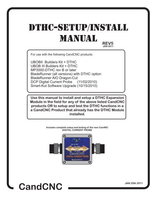
<strong>DTHC</strong>-<strong>SETUP</strong>/<strong>INSTALL</strong><strong>MANUAL</strong>REV5JAN 2011For use with the following <strong>CandCNC</strong> products:UBOBII Builders Kit + <strong>DTHC</strong>UBOB III Builders Kit + <strong>DTHC</strong>MP3000-<strong>DTHC</strong> rev B or laterBladeRunner (all versions) with <strong>DTHC</strong> optionBladeRunner AIO Dragon-CutDCP Digital Current Probe (11/02/2010)Smart-Kut Software Upgrade (10/15/2010)Use this manual to install and setup a <strong>DTHC</strong> ExpansionModule in the field for any of the above listed <strong>CandCNC</strong>products OR to setup and test the <strong>DTHC</strong> functions in aa <strong>CandCNC</strong> Product that already has the <strong>DTHC</strong> Moduleinstalled.Includes complete setup and testing of the new CandNCDIGITAL CURRENT PROBEPlasmaUnitCAL+15V -15VACTTEST20 - 125AWorkclampLeadDC AMPS<strong>CandCNC</strong>DIGITAL CURRENT PROBEModel DCP-01CLAMP<strong>CandCNC</strong>JAN 25th 2011
DIGITAL TORCH HEIGHT CONTROL MODULE (<strong>DTHC</strong>)The <strong>DTHC</strong> is a plug compatible module that will plug into the UBOB UltimateBreakOut Board card and with the proper plug-in and profile in MACH, provideadvanced Torch Height Control (including Torch on/off). The following pages gothrough the details and setup of the <strong>DTHC</strong> using the custom screens and plug-ins.The MP3000-<strong>DTHC</strong>-UBOBIII Install file on the support CD will automatically setupMACH3 with the plug-ins and profiles needed to get started. If you are upgradingan existing UBOB based system (MP3000; BladeRunner; UBOB Builders Kit) to doplasma cutting you need to verify the UBOB is a UBOB III or newer card.The <strong>DTHC</strong> is designed to work with several of our products and it’s possible to field upgradethose products with a <strong>DTHC</strong> module. The following pages are intended to cover the detailsand setup of the <strong>DTHC</strong>. For the general setup of your product like the MP3000 you shouldrefer to the manual for that product. If you do not have the manual or the Support CD youcan find the PDF files on the <strong>CandCNC</strong>.com website in the Manuals section. The supportfiles are also there as well as on our <strong>CandCNC</strong>Support Yahoo Forum in the Files section.Some complete products from <strong>CandCNC</strong> may not have the correct version of the UBOB todo a direct plug of the <strong>DTHC</strong> and there may not be a slot for the card in the front panel.Please advise us if you need a new front panel with a slot for the <strong>DTHC</strong> and which productyou have. If you do not have an MP3000 or BladeRunner in the case then you can get aspecial front panel aluminum plate that will mount the components inside your case andexpose the plugs for easy hookup. See our website for details.<strong>DTHC</strong> <strong>MANUAL</strong> REV4 10/16/10PAGE 2
PRELIMINARY TESTING THE <strong>DTHC</strong> MODULE:If you have an MP3000 with the <strong>DTHC</strong> already installed, power up the MP3000 and using asmall probe (stiff wire, paperclip, etc push the TEST Button that is recessed behind the frontpanel. Press and release one time. The yellow LED should start to flash. If it does not checkthe AC cord and plug and try again. If the LED lights and flashes it indicates that the <strong>DTHC</strong> haspower and the on-board processor is working.Further testing requires you have MACH3 installed, the serial cable attached and theMP3000-DHTC profile and screen set loaded. See the section on Loading <strong>DTHC</strong> DRIVERSBelow.LOADING <strong>DTHC</strong> DRIVERS/PLUG-INSThe Following assumes that the auto <strong>INSTALL</strong> for the MP3000 (MP3000-Install) unit hasbeen done and the basic profile has been checked and the Basic screens have been tested.If they have not, refer to the MP3000 User Manual or your Bladeruner AIO manual and performthose steps. If you are building up a unit (UBOB or UBOB Builders Kit) you need to refer to thosemanuals for the base setup. All of the plug-ins will be loaded during the base install but the <strong>DTHC</strong>install adds addtional screens, MACH profiles and Icons to use with the <strong>DTHC</strong>. Thecommunication drivers need to be configured for <strong>DTHC</strong> interface. The following steps will takeyou through setting up the system to use with the <strong>DTHC</strong> module.UPDATE: Any unit shipped after 2/25/2010 has a new auto-installer that puts both the Basic(router/mill) and the <strong>DTHC</strong> (plasma) profiles and their related screens and drivers on the PC inMACH and does NOT need the update install. IF your desktop has both the MP3000-<strong>DTHC</strong> orthe BladeRunner Dragon-Cut shortcuts then you do not need tho do the <strong>DTHC</strong> Upgrade installlisted below. All current units being shipped have the updated auto installer. The update for<strong>DTHC</strong> procedure is included for users that have an older MP3000, BladeRunner, or UBOBBuilders Kit and are adding a <strong>DTHC</strong> module for plasma cutting in the Field. From the Support CD (or a web download locate the MP3000E-<strong>DTHC</strong>-UBOBIII_<strong>INSTALL</strong> file.Run it in Windows with MACH3 NOT RUNNING. It will place two MP3000-<strong>DTHC</strong> icons on thedesktop that will Start MACH with the correct profile instead of having to use MACH Loader eachtime. It will add and configure the MACH com objects (driver). The MP3000-<strong>DTHC</strong> profile in MACHwill be added along with the matching screen sets and macros.After the MP3000-<strong>DTHC</strong> Install, open MACH3 using either the MP3000-<strong>DTHC</strong> Icon ORBladerunner AIO icon from the matching named profile in the MACH Loader.If you re-install MACH or upgrade, you may need to run the Install again.Open MACH using the MP3000-<strong>DTHC</strong>-UBOBiii or BladeRunner AIO profile (for the product youhave) and select CONFIG PLUGINS from the CONFIG menu in the top row. You will see a list ofplugins that are available At the top of the list are the two <strong>CandCNC</strong> plug-ins. Each one starts with“ccc_”Confirm that they are all ENABLED. If you make any changes make sure you close and restartMACH.Click the CONFIG (yellow) text next to the ccc_comm plugin and you will see the screen on thefollowing page: PAGE 4
Use the screen to select the hardware you are using. The Ubob THC Plugin should beselected. If you have a ESPC Power supply (part of all RouterPak and PlazPakproducts) then be sure to check that as well. Note the COM port selection box. In mostcircumstances that will stay on “1”.DYNAMIC SELF-TEST of <strong>DTHC</strong> MODULEActivate the recessed TEST Button on the front panel of the MP3000-<strong>DTHC</strong> oryour unit with the <strong>DTHC</strong> module installed and connected. The TEST LED shouldstart flashing.The unit goes into a test sequence where the TIP VOLTS DRO is set to100 and the UP screen LED flashes 5 times. Then the TIP VOLTS DRO is set to150 and the DOWN LED flashes 5 times. This test sequence repeats until you hitthe Test Button again and the TEST LED stops flashing.If the test does not show the above results the most probable cause is the serialcommunications is not working between the PC and the MP3000. Make sure youhave the right port selected. If you were sent a special serial cable with the RS232buffer module (see photo) make sure it is installed correctly.PAGE 5
J15TipVoltsWorkclamp+ [POS]L4R7- [NEG]Electrode36 THC Sensor39REV 14L2L1J1137ARC OKJ3R2VoltsTorchSwitchJ10+ArcJ5D2OKJ4TP4TP3TP1TP238THC SENSOR CARDREV 14To TORCH -(ELECTRODE WIRES)DAMGERHIGH VOLTAGEWHEN TORCHis ONMount card at least ½”from anyMetal. Use ½”or longer standoffsabove metal case Do not let shellof DB9 contact metal ofPlasma CaseTORCH SWITCHNO POLARITYR1J14Tip VoltsD6CAUTION!HIGH VOLTAGESpark GapFor HV SystemsJ17CAUTION!HIGH VOLTAGERV1J16D13CAUTION!HIGH VOLTAGEC1R8TO TORCH POS(WORKCLAMP WIRE)TO ARC XFR[OK to Move]Relay Contacts(DRY CONTACTS)NO POLARITYR6FOR CT (CurrentTransformer) InputOnly. See pageinformationNOTE: BOARD Lettering(silkscreen) on REV14cards is REVERSEDFor J11 and J10.J10 is the Torch SwitchWiresTorch SwitchTORCH RELAYArc OK[V]D22<strong>CandCNC</strong>D21TORCHACTIVEARC OKC2ARC OK LEDACTIVE ONLYWHEN CT INPUTis USED.DCPInput JackforDigital CurrentProbe (DCP)J115VR269PLUGSENSIVITY ADJUSTFOR ARC OK FROMCT Transformer ONLYNot used with otherARC OK methodsDB9 Cable toConnector on <strong>DTHC</strong>ModuleTP1 - TP2 Test voltage:When torch fired = approx1/7 of Rat TIP VOLTS.PAGE 6
CONNECTING HAND TORCH TO THC SENSOR CARDUse ScotchLoc IDC Splices (RED) to tie Torch Switch output onTHC Sensor (J10) Screw Terminals. Locate Orange and Violetwires at J10 in the PowerMAX box and tap each wire as shown.To test short two screw terminals on J10 THC Sensor and torchshould fire (Plasma Unit on)Connect to Screwterminals J10 1 & 2 onthe THC Sensor CardFROM HAND TORCH CABLEIMPORTANT: When making any connection insidethe PowerMAX disconnect the unit from the ACLine (unplug it). Do not open the case with poweron the AC line. THERE ARE DANGEROUSVOLTAGES present in the unit anytime it is connectedto an AC source EVEN IF IT IS TURNED OFF.PAGE 11
HYPERTHERM PowerMAX 45Connecting THC SENSOR CARDFOR OPERATION WITH MP3000-<strong>DTHC</strong>and BladeRunner Dragon-Cut seriesSIGNAL NAME(s)POWERMAXREFTHCSENSORREV14 REFNOTESWIRE TypeTORCH SWITCH;START - MECHTORCHPINS 3 & 4J12J10 ScrewTerm 1 & 2For use with mechanicalTorch ONLY.18-22Ga stranded lowvoltage insulatedTORCH SWITCHHAND TORCHORG & VIOwires at J10J10 ScrewTerm 1 & 2Parallel taps where TorchCable Plugs into J10 inPowerMax18-22Ga stranded lowvoltage insulatedARC VOLTS; RAWTIP VOLTSJ19 & J21insidePowermax45J14 (neg) ,J15 (pos)This is NOT the 50:1divided voltage at J12.See detailed instructions18-22 PVC stranded ,insulted, twisted pair min600V rated insulationARC OK ; ARCXFRPINS 12 & 14J12J4 & J5 ARCOK SwitchInputDry Contact ouput fromPowerMAX (no voltage)18-22Ga stranded lowvoltage insulatedDrawign not to scaleLOCATION OF J19 and J21Inside PowerMAX 45FRONTJ19 or J18(white wire)TP 19WTP 18R192 VDC192 VDC+ -+ -TP 17BJ21 (work lead)CAUTION: Make sure wiresand terminals do not touchanything but the screws forJ19 and J21. HIGHVOLTAGE IS PRESENTWHEN TORCH IS ON.To THC SENSOR CARD J15POS input terminalTo THC SENSOR CARD J14NEG input terminalPAGE 12
THIS SECTION RESERVED FOR POWERMAX 65.85 HOOKUP DATAPAGE 13
THC SENSOR CARD TESTINGBefore you make connections to the plasma unit you may want to do some testingon to confirm proper operation of the THC SENSOR with the <strong>DTHC</strong> Module. Set the THC SENSOR card on an insulated surface close to the <strong>DTHC</strong> and PC. Connect the THC SENSOR to the DB9 connector on the <strong>DTHC</strong> Module using a 25ftDB9 Extension cable (all wires straight through). Load MACH and the MP3000-<strong>DTHC</strong> (or BladeRunnerAIO <strong>DTHC</strong>) Profile and makesure you can come out of RESET and that the CP (Charge Pump) LED on the front of theUBOB/MP3000 is ON. On some products you may have to have the Motor DC on to come out of RESET Click on the TORCH icon on the screen. You should see the LED above the TORCHbutton on MACH turn on and there will be a click on the THC Sensor card and one of thesmall LED’s on the card will light. That indicates the TORCH ON relay is working. The next check is to confirm the ARC OK circuit is working. Short across the J4 andJ5 Terminals with a small screwdriver or jumper wire. The ARC OK LED on theMACH3 Screen should light. If it does you can proceed to the actual hookup of the THCSENSOR card. If any of the tests fail make sure you have the cables firmly attached and thatthey are the correct type. All of the cables we ship with any Package Deal are all“Extension” type cables with all pins straight through. All cards are checked at least twice and most three times before they leave the factory.It’s unusual for a THC SENSOR to be bad or fail in no load testing. If you have checkedall of the connections, cables and MACH setup and you still cannot get the THC SENSORto work contact us at 903-364-2740 or via e-mail at Tom @<strong>CandCNC</strong>.comNOTE: Some Larger (>100A) plasma units or older smaller models use various methodsto start the initial ARC. Most common is HF (HIgh Frequency) start. HF Start presentsseveral challenges. It uses the concept that higher frequency waves travel through air(and arc) easier than DC voltage. The HF is normally combined with a higher voltage andit starts an ARC that the plasma uses to ignite the air. Once the arc fires, if a conductivepart is close, the arc will transfer to the material. The HF start causes a lot of noise andcurrent spikes. The other form of High voltage start is the CD (Capacitor discharge)method. It is basically a high current version of an Automotive ignition system. Up to30,000 volts can be generated. If the THC Sensor is not protected, the high voltage andhigh frequency can cause component failure on the card or (worse) in the THC unit andeven burn the board. The THC Sensor (REV10 and up) is protected from HF and mostHigh Voltage start circuits. The REV 14 card has been introduced to work with any unitsincluding units that use both HF , HV and CD start.The smaller Hypertherm and other modern brand units use a low noise method called“blowback arc start”. The electrode is mounted against a spring that keeps it pushedagainst the inside of the Nozzle as long as air is not flowing. When the unit is triggeredthe starts a few milliseconds after the current starts to flow in the electrode circuit. As theair flows it pulls the electrode away from the nozzle and creates an ARC. That is usedionize the air and start the plasma.The <strong>DTHC</strong> can be used with all types of plasma units. The HF units tend to be very noisyand some even have large amounts of RFI. The total isolation of the <strong>DTHC</strong> circuit fromany low level (PC logic) including any common ground, stops any conducted noise. Theinternal circuits are protected from RFI with proper layout and careful attention to bypasscomponents on all active circuits.PAGE 14
Hooking Up Your Plasma Machine to the MP3000-<strong>DTHC</strong>/BladeRunnerAIO <strong>DTHC</strong>CAUTION: Portions of this install may include opening your plasma cuttermachine and attaching wires. MAKE SURE THE UNIT IS UNPLUGGED PRIORTO REMOVING ANY COVER(S) OR MAKING ANY CONNECTIONS. Plasmaunits have HIGH VOLTAGES present that can be dangerous or lethal. IFYOU ARE NOT EXPERIENCED WORKING WITH HIGH VOLTAGES, DO NOTATTEMPT TO <strong>INSTALL</strong> THIS OR ANY OTHER DEVICE INSIDE YOURPLASMA UNIT YOURSELF. SEEK PROFESSIONAL HELP.In order to control your plasma unit, there are three main connections that needto be made to the plasma unit itself. All of the following operations are to bedone with the power disconnected from your plasma unitYou should decide if you want to mount the THC Sensor PCB inside your plasma unitor in a small external box on the outside of the unit. You will need access to the DB9connector on the THC Sensor card so if you mount the card inside, it should beso that the DB9 is exposed. If you cut a small square in the cover or front panelso that the connector frame wil pass through and drill two holes for the connectormounting holes you can use the connector mounting jack screws to hold theboard in place. If you use an external box you will need to provide holes for thesignals listed in the following steps. If you are using the CT for ARC OK, there is atrigger level adjustment pot onthe front of the card (VR1) to adjust the level of currentthat trips the ARC GOOD signal . Drill an access hole to be able to adjust that pot.External connectors, hookup wire and external enclosure are not provided.THC SENSOR PCB <strong>INSTALL</strong>:If your plasma unit does not have an external activate (remote) torchswitch, you must find the torch activate switch connections. Normally the torchhandle wil have at least one set of small wires coming from the torch head cableand attaching to a screw terminal post inside the box. Find the point where thetorch cable enters the box and identify any small pair(s) of wires that travel up thetorch head cable. Most machines are setup to be able to change out the entiretorch head and cable assembly and will have screw terminals (or a plug) inside tomake that operation easier. Some machines have different types of specialconnectors to make changing the torch out easier so you may have to trace backwhere the wires make attachment to a terminal strip or an internal card. If youmodify any wiring or circuitry be aware it may void your warranty on the plasmamachine.PAGE 15
1. Most plasma units have connection terminals where wires from the torch orpanel connectors attach to the internal PC Boards. The terminals provide aconvenient place to do your connections. Use crimp-on spade or roundterminals to attach the wires to the terminal strips. Make sure the new wires youinstall do not touch adjacent metal objects. On some machines there may bemore than one set of small wires and are used for sensing tip shorts and otherconditions. To identity the correct pair for the Torch Switch use an ohmmeteror continuity checker across each pair while you manually push the torch headbutton. When you identify the pair make note of where they attach. Use #22 to#18 stranded wire (twisted pair) to connect between the two screw terminals onthe THC Sensor PCB marked “Torch Switch” to the two switch terminals in theplasma unit.There is no polarity. NOTE: IF your unit has noise filter chokes from thetorch switch wires up to its internal logic card, it is recommended you placethe two wires to the THC Sensor PCB on the other side of the chokes fromtheir torch head connection (end closest to the internal logic card).2. If your unit has a tip voltage connection point (i.e. like the Hypertherm1000 series), you will need to use their manual and suggestions as to howto connect to the two points and run those wires to the THC Sensor card.Just make sure you use wire that has insulation rated for at least 400 V.Small signal wire like telephone wire (UTP) is not rated that high and canarc to nearby components. The THC Sensor card is designed to take thefull tip voltage and divide and filter it. Open circuit full tip voltage can beas high as 300VDC in some machines.does not3. If your plasma unit have a designated tip voltagemeasurement point, you will need to locate a place inside the unit whereyou can get one wire onto the workclamp lead and another on the heavylead(s) that connects to the torch tip (electrode).a. Note: some machines like the Hypertherm 380 do not have a singleheavy wire to the Torch tip and instead have a set of parallel smallerwires that all terminate into one connector. In the case of the 380 theWHITE wires are the tip volts.b. You can identify both locations by visually tracing the two leads asthey come into the box. You should find several locations/terminalstrips that have connections to these two points and you can usethose for your sense wire connections. Use unshielded strandedtwisted wire of #22 to #18 ga rated for at least 400V insulation.PAGE 16
c. Make a connection between the locations you have identified that tiedirectly to the two leads (workclamp and torch tip) to the two “TIPVolta” terminals. Make sure that these wires are routed where theycannot come into contact with hot or moving components. Starting with theREV 14 THC Sensor card the TIP VOLTS inputs have a polarity. The + side4. If your plasma unit does not have an “arc ok” signal jack AND you are NOTusing DCP module you will need the external CT (current transformer). Do thefollowing:A.) Make SURE the cord to the plasma unit is disconnected fromany voltage source.B.) If you have room inside the unit disconnect one of the AC hot leads prior orfollowing the Main switch and slide the wire through the center of the current sensetransformer like a finger through a donut. (for low power plasma units less than 50Arating you may need to take more than one wrap of the single AC wire through thecenter hole)C.) There are two connections on top of the transformer and the large powerresistor supplied needs to be connected with one lead on eachconnection. In addition you need to connect a twisted pair wire betweenthe two connections and the terminal on the board marked “ARCGood”(J6). No polarity. The transformer is a current transformer andforms its voltage across the power resistor. This is an AC voltage that werectify and use to trip the Arc Good circuit /relay on the THC Sensor PCBand use the isolated relay contacts to signal the parallel port andMACH2/3. A good way to mount the current transformer inside the unit isto use a plastic cable tie and secure it to a nearby bundle of wires orbracket.5. If you are using the <strong>CandCNC</strong> Digital Current Probe (DCP), you need not hook upany ARC OK signals. The ARC OK signal is derived from the TORCH AMPS (cutcurrent) feedback. ARC OK trip point is set in the CUT PROFILES in MACH3. See thesection on installing and calibrating the DCP-01/02 on how to set the ARC OK trip point.6. If you have a plasma unit that DOES have an Arc Good signal or you have theDCP module, you do not need to install the Current Transformer and power resistor.Just make the connection to the Arc OK terminals. Some units provide only relaycontacts; (“dry Contacts”) For that type of signal the ARC OK inputs are J4 and J5 onthe THC Sensor card.Note: The term Arc Good is interchangeable with Arc Ok , Arc Xfer and OKto MOVE.7. NOTE: IT is ESSENTIAL that the chassis of the plasma unit have a goodearth ground. Refer to the suggested grounding section of the diagrams(#####) and provide for a good earth ground close to the table. A safetyground back to a breaker panel many feet away may be a good ground forAC frequencies (60hz) but poor for higher frequencies like plasma noise.Since we are bypassing any high frequency noise to the plasma chassis, ifit has a poor noise ground it can actually put noise back into the tip voltsrather than shunting it away!PAGE 17
<strong>INSTALL</strong>ATION OF CURRENT TRANSFORMERUsed for plasma units that do not haveArc Good (Arc Xfer) signal or DCPProvided Power Resistoracross terminalsWires to ARC OKAYscrew terminals onTHC Sensor Card35 to 100A range Plasma unitsPass one conductor from the AC line straightthrough the center of the Current TransformerProvided Power Resistoracross terminalsWires to ARC OKAYscrew terminals onTHC Sensor CardLess than 35A UnitsTake a full wrap with one wire fromthe AC line.PAGE 18
Digital Current Probe Model DCP-01Physical install and hookupDCP-01 Digital Current Probel uses theexisting THC SENSOR (rev14 or above)and slips over the Plasma SystemWorkclamp lead wire to provide DC ampfeedback to the <strong>DTHC</strong> and to the MACHscreen. The following series of photosshows the DCP being hooked up to aplasma cutter.Start by removing the ground clamp fromyour plasma workclamp. If it has a large ringterminal on the end where it attaches to theclamp you will need remove the ring terminaland replace it with a new one after you pushit through the DCP unit.Loosen the cable strain relief/clamps on eachend of the box by twisting the retainer nutcounterclockwise viewed from the end. TheStrain relief has an internal collar that clampsdown on the wire the more it is tightened.Straighten the wire as much as possible andstart feeding it from the right hand side.Plasma Unit EndClamp EndRight hand Strain ReliefClamp End Plasma Unit EndLeft hand Strain ReliefCable passes through center of DCP-01Push the wire through gently. If it hangs tryrotating the wire and pushing but do notforce it. There is a round hole in the Hallprobe inside the box that the wire has topass through. It is located close to the rightside of the unit. If you have problems gettingthe wire to go though pull the wire out andremove the 4 screws holding the top andremove the top and the PCB with the HallProbe (see next page). Thead the wirethough the right side strain relief and pullenough through so you can thread the HallProbe on the card and then over and out ofthe left side strain relief.PAGE 19
Workclamp Lead Wire goesthrough Hall Probe center asshown. Top shown flipped 180degsNOTE: Your DCP-01 unit will ship with a8 ft interconnect cable to connect it tothe THC SENSOR card. That connectionis covered in the Setup and Test sectionfor the DCP and comes in the side of theunit. If you remove the top cover pullcarefully to prevent breaking ordisconnecting the interconnect cable. If itcomes loose the DCP setup section hasthe wire colors and hookup for the cableWhen you have the Workclamp lead wire threaded through the box, hand tighten the outsidenuts on each strain relief until it is tight around the cable. It is important that each end issealed to keep out plasma dust and smoke. Position the DCP-01 along the cable close tothe plasma unit and in a place it will not get stepped on, crushed or can will dragged acrossthe floor if you decide ot move your plasma unit or use it manually in the shop. Theenclosure is sealed and rugged but it can be damaged by excessive abuse.PAGE 20
<strong>SETUP</strong>, TESTING and CALIBRATION of the DCP-01 DIGITAL CURRENT PROBEDo the following steps in order:1. Connect the DCP-01 interface cable to the THC SENSOR using the wirecolors and screw terminals on the THC SENSOR as shown. Most THCSENSOR cards were shipped without the plug screw terminals on the 5exposed posts. You DCP-01 ships with 2 dual plug-on screw terminals.Place them on the posts and carefully strip back about 1/4” of eachconductor, insert and tighten the top screw down until a tug on the wire willnot pull it out of the terminal. If your THC SENSOR is mounted in a box orinside the plasma unit then you will need to make provisions to route the wireto the THC SENSOR. Keep the DCP interface cable away from the highvoltage TIP Volts end of the THC SENSOR card. If your THC Sensor card isinside the plasma unit keep the DCP interface cable at least 1” away from anhigh voltage cables in the unit. Do not cable tie the Interface cable to othercables in the box unless you know they are low voltage cables. If you areconnecting up your <strong>DTHC</strong> and THC SENSOR for the first time make theconnections to the THC SENSOR card and the DB9 cable back to the <strong>DTHC</strong>module (front Panel connector on the MP3000-<strong>DTHC</strong> or the BladeRunnerDragon Cut. Do this BEFORE you make the Tip Volts (Arc volts) connectionor the TORCH SWITCH. You can run some tests on the THC SENSOR Cardand the DCP without having the plasma unit turned on or the Tip Voltspresent.DCP Interface Cable+9 to +12 from <strong>DTHC</strong> ModuleCom (return) for 9 - 12 from <strong>DTHC</strong>Shield (if used)DCP PWM signal BACK to <strong>DTHC</strong>36 THC Sensor39REV 14L2L1C2J3D22R2Arc OK[V]<strong>CandCNC</strong>DCPARC OK LEDACTIVE ONLYWHEN CT INPUTis USED.TorchSwitchD211J10ARC OK2+3J4J5D2TORCHACTIVE4J5J45TP4TP3J1TP1TP2DB9 Cable toConnector on <strong>DTHC</strong>ModuleJ11TORCH RELAY37ARC OKVoltsTorchSwitchPAGE 21
2. Start MACH3 on the controller PC and load the profile and screen set for the<strong>DTHC</strong>. If this is the first time you have used the <strong>DTHC</strong> and MACH you should havehad MACH loaded and setup. If you do not, STOP! Go back to the MP3000-<strong>DTHC</strong>or the BladeRunner AIO manual and first setup MACH and get your table moving andthe proper MACH profile loaded for your system.This dialog box or one similar to itshould appear in the center part ofyour MACH main screen if you arerunning the right profile. Theimportant readouts (DRO’s) are theTORCH AMPS. We will be using theTORCH AMPS readout to calibratethe DCP and then use the StoredSettings Button to preset somevalues for the DCP. It’s importantthat you have gone through the<strong>DTHC</strong> setup in this manual FIRSTand that you have confirmed (usingthe DTCH self-test button that it isworking properly. The <strong>DTHC</strong>ONLINE Led at the bottom should beON (Green). If it is NOT you cannotgo further in the DCP setup until theissue is resolved!3. Power up the MP3000-<strong>DTHC</strong> or the BladeRunner (oryour UBOB Builders Kit + <strong>DTHC</strong>) so the <strong>DTHC</strong> modulehas power. The first thing you should see is that the +15LED and - 15 LED on the font of the DCP light up. TheACT (activity) LED will NOT be on.4. Bring MACH out of reset. On any unit with our ESPsmart power controller (including Bladerunners) youMUST have the DC power to the motors on to come out ofreset. At this stage you should have MACH setup,running and know how to come out of reset.5. Make sure that the <strong>DTHC</strong> module is communicatingwith MACH. The <strong>DTHC</strong> ONLINE Led should be ON(green) When you activate the <strong>DTHC</strong> Self-test theTORCH VOLTS should change from 100 to 150 and theTHC UP and THC DOWN leds (and ARC OK) willalternate off and on. The TORCH VOLTS comes from the<strong>DTHC</strong> across the PC serial port connection to MACH.Without the serial communications you will not get TorchVolts and you will not be able to see TORCH AMPSPAGE 22
6. Once you have determined the <strong>DTHC</strong> passesself-test then locate the small hole in the front ofthe DCP unit (marked CAL and TEST). You willneed a small screwdriver or probe tip(paperclip?). You will feel the button click. Pushit once to turn on the TEST/CAL function. Whenit is active the ACT LED (yellow) will flash.TO TURN OFF TEST/CAL MODE on the DCP-01 push the recessed CAL/Test button onceand the ACT LED should stop flashing and theTORCH AMPS readout should return to 0Calibration/Test Button(recessed)7. While you are in TEST/CALmode (LED blinking)the TORCH AMPS should display a value. If you areinstalling a DCP on an existing product with a <strong>DTHC</strong>the calibration will be off so the number you seecould be anything from ___ to ____. I your unitdisplays 100 volts as shown then you continue on tofinal testing and CUT PROFILE Setup. IF YOURVOLTAGE IS NOT 100 You will need to proceed tothe CALIBARATION SECTIONCALIBRATION of the DCP-01Use this section any time you put the unit into TEST/CAL and the displayed value inthe TORCH APMS readout is NOT 100 as shown.1. To calibrate the <strong>DTHC</strong> module to the DCP-01 you must have access to the top ofthe <strong>DTHC</strong> Expansion Module. Refer to your product manual to identify and access the<strong>DTHC</strong> module. It is the small PCB card behind the panel on all <strong>CandCNC</strong> units wherethe DB9 cable from the THC Sensor plugs in. In most cases all you have to do to gainaccess is remove the top cover (MP3000-<strong>DTHC</strong>) or the Front panel (BladeRunnerAIO). Use the photos below to find and identify the <strong>DTHC</strong> card and the correctadjustment point for the DCP. CAUTION there are two identical pots (variableresistors) in the card. One is the DCP calibration pot. The other is the TORCHVOLTS calibration pot and is set at the factory DO NOT ADJUST THE WRONGPOT. IF YOU ACCIDENTLY CHANGE THE TORCH VOLTS (wrong pot) you willthrow your <strong>DTHC</strong> unit out of calibration and without a know accurate source ofvolts on the TIP Volts input of the THC SENSOR card you will not be able to get itback in calibration!Check the photos. Study the board orientation and MAKE SURE you are adjusting thepot. This calibration should only have to be done once so take the time to do it right.DCP Calibration (Cont)PAGE 23
<strong>DTHC</strong> EXPANION MODULE. Locatedabove the UBOB III card in most <strong>CandCNC</strong>products.. Ribbon cable connecting <strong>DTHC</strong>down to UBOB card may cover adjustmentpots. If so, gently move it out out the way.Do not unplug the ribbon cable or the cardwill be disabled.Green Power LEDShold be ON2. Using the diagram below and with theDCP in the TEST/CAL mode (LEDflashing) adjust the DCP calibration potwhile watching the TORCH AMPS DRO inthe MACH screen. Adjust the pot until thevalue displayed is 100 AMPs.16 pin header (plug)for <strong>DTHC</strong> to UBOBCableYour calibration procedure is complete!<strong>DTHC</strong> Self TestLEDDB9 connector for cable toTHC SENSOR CARDDCP CalibrationPOT ADJUST perthe instructionsNO!TORCH VOLTS CalibrationDO NOT ADJUST THIS POT.Unit is calibrated at thefactory.PAGE 24
OPERATION of the <strong>DTHC</strong> with the DCP-01.The primary purpose of the DCP-01 it give the operator real time feedback ofthe actual Cut Current. Using the settings in the Cut Profile you can set faultpoints (based on a percentage of the varience from the current preset value towarn the operator if cut current is too high or too low. The ACT LED on thefront of the DCP-01 (when not in Text/Cal mode) will light up anytime thedetected current is above 20A It’s just a visual indicator that the DCP-01 isreading current. If the LED lights when you fire the torch and have a valid arcand you do not see the Current displayed on the TORCH AMPS DRO on theMACH screen then go back through the test and calibration section. If yousee cut current out of range or get a Current Fault then check the workclampconnection, the current setting on the plasma unit, the consumables, the CutCurrent setting in the Cut Profile (stored settings) and determine why thecurrent is not what it should be.It’s important to understand that the CUT PROFILE does NOTsetthe cutting current. Only the manual adjustment on the plasma unit setsthat value. The DCP-01 just tells you what the cut current REALLY is atthe cut and tells you if the value is not what you have set in the specificThis LED comes on any time detected current is 20A or greaterPAGE 25
PC w/MACH3Grounding practices to reduce noise and increase safetyMP3000-<strong>DTHC</strong> Interface/Control BoxNote THC Sensor Card shielded cableis not connected to any ground in the Control boxDo NOT Ground PC or Controllers toEarth Ground Rod. Conrollers will reference themselvesto power ground through their AC linesController CabinetMP3000 and UBOB have built in isolation on all inputs from the tableto prevent noise transfer and ground loopsTHC Sensor CardCNC PLASMA TABLEUse ground strap to gantry from tableTabel I/OCard(limits, homeAux relay)PLASMAUNITAttached to metalChassi#10 to #4 Ga heavy wireGantryGround Rod or Metal polein earth groundGround runs shouldbe less than 10’Grounding plate#10 to #4 Ga heavy wirePAGE 26
That concludes the internal connections you will have to make for your unit.Make sure all leads are insulated and away from possible physical damage.Double check to make sure there are no loose connections and that you haveattached/ re-attached any wires mentioned in the above guidelines.Replace all covers and safety devices on the plasma unit and plug the plasmaunit into power with the unit switched off. Turn the unit on, and make sure theunit works correctly in manual mode. (i.e. cut a piece of metal by hand). If youhave a machine torch manually fire the torch from the Torch On button in MACH3PAGE 27
SETTING UP YOUR Z AXIS FOR AUTOMATIC TOUCH-OFF. Make sure your Z is calibrated. When you move it 1” by the DRO it actually movesexactly 1”. If it does not find the axis setup section in the manual for your control and runthe axis setup and calibration. All axis MUST have the correct Steps per Unit setting inMACH. Check to make sure your Z HOME is working. Make sure MACH is out of RESET.Open MACH to the DIAGNOSTIC Tab and watch the upper right quadrant while youmanually trip the Z switch on the Floating Torch Holder. It should light the Y Home LED(only). Raise your Z above a piece of material. Run a Ref Z move on Z by clicking on theRef Z button next to the Z DRO (readout). The Z should start to move down towards thematerial. If it moves in the wrong direction STOP the move and use the CONFIGHOMING/LIMITS in MACH to change the polarity of the Home Neg value. To change itclick on the symbol (green check or red X) and it will change to the other value. Save it byclicking OK. When the Torch Tip hits the metal the Z will continue to move down until it trips theswitch. The Z should stop and reverse slightly. Use the Z Zero Button (next to the Z DRO) and reset the Z DRO to 0.000.You may want to lower your Jog % in the Diagnostics Tab to 10% or less to slowdown the manual jog rate. Carefully jog the Z up using the keyboard hotkey (default isPage Up Key) until you can slip a piece of paper under the torch tip. Perform the move again and confirm the value. Once you have several readingswithin .005 then write down the Z DRO reading The value you have is the Net Switch Offset and will be used in either MACH OR inSHEETCAM (post) but NOT BOTH.PAGE 28
Establishing a material Zero with a floating head and sensor switchSEE PREVIOUS PAGE:a. Note to SHEETCAM (and SheetCAM TNG) users.We have provided special Posts for MACH3 and the MP3000-THC to be used whengenerating output from SheetCAM. It has an automatic “touch-n-go” feature that reads thetraveled distance and once it exceeds 500mm (about 20 inches) a Z reference isperformed just prior to the next pierce.This post is intended for use with the MP1000-THC and MP3000-<strong>DTHC</strong> and a floatinghead setup ONLY. The latest versions of SheetCAM TNG ship with several MP1000named posts. They will work with all of our THC products (MP1000, MP3000, <strong>DTHC</strong>,LCTHC, etc)If you are using SheetCAM you need to open the specific posts (or posts) you use with atext editor and find the line in the post that sets the value of the SwitchOffset. It will looksomething like this:dist = 9999999refdistance = 10* scale--Put your switch offset value hereswitchoffset =.052lastz = 0The switchoffset value needs to be set to the number you wrote down when you did thetests on the previous page ( SETTING UP YOUR Z AXIS FOR AUTOMATIC TOUCH-OFF).Make sure you save the file with the .post or the .scpost file extension it had to start with.refdistance is the distance you let XY travel before you do the next touch-off sequence.You can change how close (and how often) that sequence happens by raising or loweringthe value. Scale in this context is 25.4. Refdistance in in mm so in the example above theactual distance is 254 mm (about 10 inches). That is the combined distance of both X & Ymovement. On thin material that may need a touch off before every pierce that the numberto 0. Save the POST with another name and select it when doing your final CAM post toG-code.b. For non-SHEETCAM users.Mach 3 provides added THC functionality and has inputs for pierce height, initial cutheight , etc. At this point we have not tested those features so their use isdiscouraged. It is recommend that any references for the Z while cutting be edited into theg-code as:G00 Z.75G28.1 Z.5G92 Z0G00 Z[your switch travel here in decimal]G92 Z0G00 Z.5This should be inserted just prior to the Torch ON (M03) event at any given pierce pointwhere you wish to re-reference the ZPAGE 29
PAGE 30
6. Cut quality in plasma is a function of several factors:· Clean DRY air.· Sufficient and consistent air pressure (typically 65 to 80PSI)· Good consumables.· Accurate Pierce Height (Initial Height Sense)· Proper Cut Height (Proper adjustment of THC voltage)· Correct Pierce Delay· Proper Feedrate (cutting speed)· Proper settings of the THC Rate and CV settings inMACH3· Cut Profile Settings for Span and Tip SaverIf your cut edges are flared in or out check all but the lastfactor. If your MP3000-<strong>DTHC</strong> does not respond fast enoughon uneven(warped/un-level)material you may need toincrease the THCRate(percentage of MaxZspeed) in the MACHSettings Tab from 20%to as high as 50%.Do not go much higherthan 50% on a stepper axis, since while theTHC has control of theZ, accel/deccel settings for the motor are ignored. If the cuts arejagged on curves, or the movements of the machine becomes jerky,you may need to alter the values for Constant Velocity tuning inMACH3. Each machine is different and the values are preset for avalue that works with most machines but your results may vary. Seethe section in the MACH Manual for CVtuning for suggestions1. Setting the Arc Good trip point. If you are using the supplied CurrentTransformer for Arc Good sensing, It is possible that you will need toadjust the trip point of the ARC GOOD circuit by adjusting it with VR1 onthe THC Sensor Card. Turn the control fully counterclock wise anddetermine it if lights the ARC GOOD led on the MP3000-<strong>DTHC</strong> Screenwhen firing the torch against the metal. (doing a normal pierce). If it doesnot light it is possible your torch is a smaller unit and you need to changethe value of the power resistor at the Current Transformer from the 15ohmto a 30 ohm. Make sure you disconnect the plasma until fromany power BEFORE making any of the listed modificationsUnits smaller than 35A ratings (especially if they are wired and runningfrom 230VAC) need the higher value of resistor. Another change is to takethe AC line going through the CT hole and loop it through another turn sothere is a full loop. (See diagram #####) This doubles the developedvoltage per amp of current. Once the Arc Good LED comes on you shouldslowly increase the setting until it ceases to turn on with a valid pierce oryou hit the stop. In either case back the pot off of the max setting so youare about 2/3’s of the way between the Min setting and the Max setting.The goal is to have the Arc Good fire when there is a valid arc under mostof the current settings you would use with your machine but NOT when it isjust idling or firing the torch in the air.NOTE: If you are usingthe <strong>CandCNC</strong> DigitalCurrent Probe (DCP) itcan (and should) be usedfor ARC GOOD (ARCOK) sensing. Thefollowing setion on the<strong>DTHC</strong> settings using theCUT PROFILE windowexplains how to use theDCP and set theparameters for ARC OK.The DCP is a recentaddition to the <strong>DTHC</strong>product line and brings anew dimension to theplasma cutting process..PAGE 31
MP3000-<strong>DTHC</strong> Screen SectionThe following pages cover the operation andscreens involved with the CUT PROFILES andthe <strong>DTHC</strong> section of the screen.NOTE: The <strong>DTHC</strong> is usedin all of our Plug-n-Runproducts including theMP3000, BladeRunnerDragon-Cut, and the UBOBBuilders Kit + <strong>DTHC</strong>. If thetext refers to one of thespecific products then takethat to mean the same as“any <strong>DTHC</strong> based product”in this sectionTORCH HEIGHT CONTROL sectionTHC ON/OFF BUTTON: The THC functions in MACH are controlled by theTHC ON/OFF button on the screen. If The LED above the THC ON/OFFbutton is greyed out (off) then the THC inputs to MACH are ignored. It alsoturns off the “Hold for Arc OK” function in MACH so that you can have XYZmotion without getting an ARC OK from the THC Sensor Card (at the plasmaunit) If you have the Auto THC ON box checked (in the Cut Profiles Popup)the THC will automatically activate when the RUN button is pressed to runG-code. There may be times you wan to run without THC or to tune the THClogic in MACH ON/OFF while cutting. You can use the THC button to do that.The TORCH ON/OFF button controls turning the Torch on/off. Under normalcutting condiitons (e.g. running from code) the Torch ON/OFF is controlledfrom the software. You have the option of turning the torch on or offmanually using the button. The Torch button will fire the torch anytimeMACH is out of RESET. The TORCH LED above the button shows thestatus of the Torch output. When it is illuminated the signal is being sent tothe Mp3000 to turn on the torch. Anytime the Torch is on (or should be on)through manual OR software activation that LED should will be on.The TIP SAVER LED is a indicator to let the operator know that the <strong>DTHC</strong>TIP SAVER circuit has activated and has locked the Z down movement. Theparameters used for the Tip Saver are set in the <strong>DTHC</strong> Cut Profiles Popupwindow. The settings and operation of the <strong>DTHC</strong> is covered the <strong>DTHC</strong>Operation and Setup and the CUT PROFILES part of the manual. NOTE:It is normal for the TIP SAVER to go active at the end of a cut where youwould normally get a head dive or as it’s cutting if it cuts across or very closeto an existing cut. If the torch preset value is wrong for the type material andtip you are using then the TIP SAVER may come on and stay on. Checkyour settings if this occurs.PAGE 32
TORCH HEIGHT CONTROL section (continued)Tip Saver ON/OFF [new]. The Tip Saver ON/OFF button and IndicatorLED allows the TIP Saver feature to be disabled. It’s used duringsetup to get the calibration (Preset Volts) within range and to test toobserve the actual cut gap. Once you have those parameters set andstored in the Cut Profile it’s recommended you turn the Tip Saver backon to prevent head dives and tip crashes. If you have conditionswhere the Tip Saver stays on during a cut it indicates the voltagesettings or cut current is set wrong. Correct the problem and run withthe Tip Saver engaged.UP & DOWN LED indicators. These two screen LEDS in MACHshow the actual UP and DOWN commands MACH is receiving fromthe <strong>DTHC</strong> Module. As the torch cuts and with the <strong>DTHC</strong> active, youwill see the UP and DOWN LEDs change. It will tell you at a glancethat MACH is getting the proper signals and coupled with the TIPVOLTS DRO show you the activity of the <strong>DTHC</strong>. The UP and DOWNLED’s also function as feedback when the MP3000-<strong>DTHC</strong> Self Test isactivated. Please see the setup and testing section for moreinformation. The UP and DOWN signals come into the isolated inputsin MACH and are on the high speed parallel port. This information isnot carried on the slower serial interface.ARC OK Indicator. The ARC OK is a intergal part of our cuttingsystem. It is a signal that tells MACH (and the <strong>DTHC</strong> module) youhave a fired the torch and it has a valid arc and you are ready to cut. Italso detects the loss of arc and MACH will stop movement BUT notturn off the torch output signal. THe <strong>DTHC</strong> can be set to do thatfunction independant of MACH (see the section on General THCSettings). If you do not get Arc OK MACH will not release motion andthe <strong>DTHC</strong> will not start processing data to send UP and DOWNcommands to MACH. Some Plasma units have a signal (normally “drycontacts...which are basicly relay contacts with no connection to theinternal circuit or voltage. On other machines you may have to orderthe optional Current Transformer (CT) part # CT-01 kit to get an ARCOK signal. IT’s a REQUIRED SIGNAL.PAGE 33
ALTERNATE SCREEN SET FOR SMART-KUTUsing Smart-Kut for Plasma.NEW FEATURESmart-Kut is an exclusive feature of the <strong>DTHC</strong> from <strong>CandCNC</strong>. It allows the operator tolet the <strong>DTHC</strong> set it’s own PRESET VOLTS value rather than taking it from a Cut Profileor from the screen settings.Here is how it works:The operator presses the Auto Learn button once and the NEXT CUT LED willilluminate. At the next start point (Torch On event) the SMART KUT will wait until thetorch has fired, moved from pierce height to Initial cut height (Beginning cut height asset in your CAM POST) and then delay for the period defined in the THC DELAY in theCUT PROFILES (see the DCP manual for setup and calibration). The Auto Learnprocess starts after the preset THC Delay in the Cut Profiles and runs for 1.2 seconds ofcut. It averages all the readings during that period and then sets the PRESET Value tothe averaged value.THC DELAY (variable)AUTO LEARN (1.2 sec)TOTAL SMART-KUT CYCLE TIMEThe function can be put into continuous mode by pressing the Auto Learn button twice.The Continuous LED will light and the torch will Auto Learn on every cut. Pressing thebutton while in Continuous Mode turns the Mode OFF.NOTE: It is not a good idea to use the Continuous Mode on a job with mixed types ofcuts. Some cuts may not be long enough or may be small enough to keep normal cutrates from being achieved (like holes and detailed scroll work) so the Auto Learn will“learn” the wrong value.IT IS EXTREMELY IMPORTANT that you have the Floating Torch Holder setup,operational and calibrated. The Auto Learn works on the principle that the touch-offsequence is finding the top of material, accurately backing off (Switchoffset value inSheetCAM), that the pierce height is accurate, that the Initial Cut height (height thetorch moves to from the pierce height) is accurate, and is the correct value for the torchyou have. If the touch off sequence is wrong, so will be the value the Auto Learn sets.DO NOT USE THE SMART-KUT Feature until you have the torch cutting correctly usingpresets and it is touching off correctly EVERY TIME! SMART KUT will not compensatefor not having the system setup and working correctly!PAGE 34
MP 3000 CONTROL SECTIONThe MP3000 Control provides controls to change the cut parameters forthe <strong>DTHC</strong>. It allows the operator to set and change values before andwhile cutting.UP ARROW Button: The UP arrow increases the PRESET VOLTS byone full volt per click in essence raising the torch and increasing the gap.It increments the PRESET VOLTS DRO and automatically sends thevalue to the <strong>DTHC</strong>. This can be useful since you can change thePRESET VOLTS while cutting which will adjust the CUT GAP at theTORCH. Sometimes a volt ot two of “tweek” can improve the cut. At theend of the cut the Current Settings will remain (for the next cut) and theybecome the new “Current Settings” in the memory of the <strong>DTHC</strong> so if thesystem is shutdown, the next time it comes up, the values will be the newsetting. See the section on using the Cut Profiles button.DOWN ARROW Button: Performs the same function as the UP ARROWbut decrements the PRESET VOLTS DRO (value). It has the same effectas lowering the torch and decreasing the Tip Volts.SEND to MP3000 Button: This button is provided in the event you entera value directly into the PRESET VOLTS DRO and then need to updatethe current settings with that value. To enter a value into a DRO you mustselect the DRO (backgound color will change), Type in the new value andhit ENTER on the keyboard. If you fail to hit ENTER the value will not“stick” and reverts back to the previous value. Do not use the direct DROinput while cutting! It made to change the value by a large amount likewhen you change tip sizes or go to Fine Cut Consummables. Normally afew volts is all you need to adjust to make a big difference in the cut gap.TORCH VOLTS DRO Shows the actual volts at the Torch Tip. It willchange as the Torch cuts but with the <strong>DTHC</strong> engaged (and the THCbutton in MACH3 Active) it should track closely the PRESET VOLTSprovided the TIP SAVER or THC FAULT has not been trippedPAGE 35
To Adjust PRESET Volts (andheight) in one volt increments clickthe UP or DOWN ButtonsActual TORCHVOLTS at the TIPTarget volts youwantActual TORCHAMPS at the TIPMP3000 Conrol Secion (Cont)PRESET VOLTS. This is probabaly the most important DRO on thescreen. It displays the “target” voltage you need to achieve a givengap. It forms a feedback servo circuit that will read the actual trochvolts, compare it the the Preset Volts and raise or lower the torch (viathe Z) to try and make them match. If you have the Preset voltsentered correctly for the specific tip, current and material the gap willbe correct. If you are off a few volts you can get a condtion where thetorch pulls up and out if the cut OR moves down and hits the metal. Itcan cause another condition where the TIP SAVER locks the downmotion (which is what it is supposed to do). It is important the youhave the proper value if Preset Volts. If your plasma unit has anoperator manual with cut charts then the preset (target) voltages willbe listed and are a good starting point. If your plasma does not havea chart you will have to build one yourself. Set the Tip SaverPercentage to 10% in the Cut Profile (see CUT PROFILE Functions)and setup a manual cut so you position the cut gap manually (abovethe material) and make a line cut. Observe the TORCH VOLTS andestablish a voltage average and use that as the beginning PresetVolts for your automated cut. Most plasma units cut from 100V to 150VDC for normal nozzle (tip sizes) and from 75 to 90V for smaller (FineCut) tip sizes. The Preset Volts DOES NOT SET THE HEIGHT itestablishes a voltage (reference point) like an auto-pilot that will adjustthe Z to match the Torch Volts (actual gap volts) to the Preset Value.TORCH AMPS. This DRO is active ONLY if you have the optionalDigital Current Probe. It will display the ACTUAL cutting current ofthe plasma cutter in real time. It should display close to the settingyou have on the front of your plasma cutter while the cut is beingmade. There are settings in the CUT PROFILE that can be used withthe TORCH AMPS to provide trigger points to warn the operator andan option to STOP the machine.PAGE 36
USING TORCH AMPS FOR TROUBLESHOOTING A BAD CUT.The TORCH AMPS can be a valuable tool to help diagnose and fix poor cutting or loss ofarc and other annoying problems. Not all cut issues are from improper current but a goodplasma cut cannot occur if the cut current is too far out of the specified value. The wholeprocess of Torch Height Control depends on the current being constant and the value seton the plasma unit.If you are experiencing problems cutting with the <strong>DTHC</strong> and it has passed all of the selftests, then setup and make a manual cut at a constant height (the recommended Cut gap)and watch the TORCH AMPS DRO. While cutting it should be close to the value you haveset on the plasma machine front panel (dial value) If it is not here is a list of things tocheck:TORCH AMPS TOO LOWTORCH AMPS VARIES DURING CUTBad Workclamp Connection (either end)Workclamp not on materialCurrent Setting on Plasma Unit wrongPlasma Current not calibrated to knobBad Workclamp Connection (either end)Bad material (rusty/dirty)Worn defective consumablesTORCH AMPS TOO HIGHCurrent Setting on Plasma Unit wrongConstant Current circuit in Plasma Unitnot workingPAGE 37
CURRENT SETTINGS BUTTON: Shows the current profile and settings being used by the <strong>DTHC</strong>.The <strong>DTHC</strong> uses a real time processor to process the torch volts and send the proper signals toMACH. The processor stores the settings in NVRAM (non-volatile ram) Changing any setting in theSettings Group or the General THC Settings and using OK (closes the window) saves the profile(writes it to the <strong>DTHC</strong> processor RAM. You must close the window to be able to access the MACHscreen and to move the machine (JOG) or RUN g-code. Cancel cancels any changes you havemade before you exitThe <strong>DTHC</strong> module “remembers” the settings you used last even if you power everything off. The CutProfile values are sent to the <strong>DTHC</strong> module (via a serial connection from the PC to the UBOB and upto the <strong>DTHC</strong> module) The “Current Values are what is in the <strong>DTHC</strong> memory. Values are transferredwhen you hit OK NOT when they are just displayed. ONLY the CURRENT SETTINGS values arewhat the <strong>DTHC</strong> uses during cutting. If you pull up a profile and do not transfer it to the <strong>DTHC</strong> modulePROFILE LIST BOX : Shows a list of all saved profiles. Any profile can be selected and thoseparameters will be transferred to the Current Settings screen. You can Add new Profiles using theAdd button . To delete an entire profile. highlight the profile by clicking on it and hit the DeleteButton. If for any reason the <strong>DTHC</strong> module has lost communication with MACH the settings onthe screen ARE NOT SAVED to the NVRAM and opening the screen again to display CURRENTSETTINGS will show the old settings. Check to make sure the THC ONLINE LED is on.PAGE 37
Adding Profiles. As you do cutting on your table using the <strong>DTHC</strong> Digital Torch HeightControl you will be able to choose optimized settings for each type of cutting you do.You can edit and save an existing Cut Profile or ADD a new one of you own. Sincethere are variables that change from one machine to another the sample values mayor may not be usable in your environment. It’s best to start out with the defaultSettings and use the Tip Volt Preset recommended by your plasma manufacturer. Ifyour plasma machine has no documentation or recommended cut charts thengo to the Plasma Setup section in this manual and use the Initial setup andcalibration methods to establish a base line for building your own charts. Thetwo most critical components are the feedrate (set in the G-Code and CAM program)and the Tip Volt Preset. Since both values vary between machines it’s best to run aseries of tests. Even the cut gap (distance from the tip to the material) and the gapvolts (actual tip volts) varies from one plasma manufacturer to another. Example: AHypertherm G series calls for .063 (1/16 ) cut gap and a tip volts reading of 140VDCon 10Ga material with a 40A tip. A Thermal Dynamics unit uses a wider cut gap(about .1 to .12) and lower tip volts (about 110VDC) for the same material. Othermachines will vary. It’s best to develop your own values for your machine over timeand store them in the Cut Profiles. NOTE: The Cut Profiles are stored in a flat filenamed THC_Profiles.txt located in the main MACH3 folder. It’s a good idea to backup your MACH settings (XML files), Screens (SET Files) and the Cut Profile listed.Restoring values from a backup copy can save hours or frustration.PAGE 39
INFORMATION GROUP:The Information section at the top of the window is for storing informationthat you can refer to. It saves time by having the vital cut parametersinstantly available to the operator The information group does not setanything for cutting and will not modify any cut parameters from theg-code. It is there to use as a reference in place of having to go to theUser Manual and Cut Charts to get the numbersPROFILE NAME: The Profile Name is important because that isthe name that shows up in the Profile List Box. Use names that will helpyou find the right profile quickly.MATERIAL: Allows you to list material detail. It helps the operatorconfirm that the setting matches the material being cut.FEEDRATE: The recommended Feed Rate, This is informationalfor reference only and does not set the actual feedrate the file runs at.It gives the operator a value to confirm when the job runs. Feedrates areset in g-code (from the CAM program). The operator can use theFeedrate Override controls on the Program Run Screen to adjust thefeedrate.TIP SIZE: Memo field to remind the operator what size tip (nozzle)to use for cutting. Typically tips are rated in “AMPS” with common sizesbeing 25, 30, 40, 60, 80 and larger on bigger plasma cutters. The orificesize is the primary difference between tips. The smaller the orifice thelower the current rating. Smaller tips cut with a smaller kerf width and atlower feedrates and current settings. The plasma manufacturers suggestusing the smallest tip (nozzle) size for a given material thickness (fromtheir charts) to get best cut quality. If you cut 16ga with a 60A tip youshould expect less than optimum cuts. Merely turning down the currenton a larger rated tip is not the same as using a smaller tip size and resultsin different arc voltage (Torch Volts) requirements to maintain the correctarc gap.PAGE 40
<strong>DTHC</strong> SETTINGS GROUP in Cut PROFILESSETTINGS GROUP:The Settings Group consists of important values that the <strong>DTHC</strong> uses to cut with. These values arenot taken from code and need to be correct for the type of cutting you are doing. Changing a valuein this group will change the way the <strong>DTHC</strong> reacts and cuts. Typically the default values will workfine. Do not make large changes in numbers to try and fix a problem. Change one parameterat a time. If you have been getting good cuts on the same type of material and the cut qualitychanges or the <strong>DTHC</strong> will not track correctly you should not start making changes in the Settingsvalues to try and correct the problem. You should confirm that all external influences have beenchecked and eliminated. Worn or clogged tips, electrodes or vent holes around the nozzle willcause cut quality to suffer. The air supply most be dry and clean and of sufficient volume. Theworkclamp lead should be clean and clamped tightly onto the workpiece. Often just clamping it tothe table is not sufficient and can cause tip volts to vary and the <strong>DTHC</strong> to cut above or below theproper height,Tip Volt Preset.(Volts) This is the value you use for the Preset for tip volts. It is sometimescalled the TARGET value. Plasma cutting is done with the tip above the metal. The Arc Gap(distance between the tip/nozzle and the material being cut) determines the tip volts (and viceversa) . Change one and you change the other. The wider the gap the higher the actual tip volts.The <strong>DTHC</strong> reads the actual tip volts and compares that to the Preset Tip Volts, and decides if thetorch head needs to raise (UP) or lower (Down). It is, in essence, a servo system that tries to keepthe gap constant by keeping the actual Tip Volts equal to the Preset Tip Volts. Study the section onProper Plasma Cutting and understand the relationship of Preset and Actual tip volts.SPAN GAP (VOLTS): This is the tolerance range in which the <strong>DTHC</strong> is “satisfied” with thematch between the Preset Tip Volts and the Actual Tip volts. It is set in 1/4 volt increments. Thelowest setting is 1/4 volt. As long as the actual Tip Volts is within the setting the Torch will not go UPor DOWN. For most cutting a value of “4” (meaning 4/4 volts or 1 volt) is recommended.This value can be changed to give more or less tolerance. For small tips or Fine Cut tips a value of2/4 (1/2V) will provide finer cuts. On bigger tips and thicker material the value can be raised slighlty.THC DELAY (sec). This is the time the <strong>DTHC</strong> waits before it starts to measure the actual tipvolts immediately following a pierce. The pierce is typically down at a height greater than the cutheight (usually about 2X normal cut height). The gap is wider and the voltage spikes as the pierceis being made. If the circuit starts to measure voltage before the end of the piece cycle it can causethe TIP SAVER cut in and prevent the Z from moving down from pierce height to Inital Cut Height(Head Lock) The circuit will remain locked as long as the voltage is the percentage out from thePRESET VOLTS VALUE. If the tip stays too high it may trigger the UPPER FAULT Limit anddepending on the settings in the General THC Settings group, issue a STOP and turn of the motionand Torch. This can all happen in fractions of a second and just looks like a misfire and stop. Forthis reason we have a minimum of ½ sec (.5) in the THC delay. IF you see conditions where theTIP SAVER locks on (LED stays on with the torch Fired, and keeps the torch from moving all theway down to proper cut height you should adjust the THC Delay value up by ½ sec incrementsuntil at the fault/lock condition no longer occurs.PAGE 41
TIP SAVER %: This value determines the lowest the <strong>DTHC</strong> will let the torch head go downbefore it locks movement. It’s a percentage of the Preset Tip Volts. It constantly measures theactual tip volts and if the value is too high,it keeps the Torch from moving down any lower.(remember that if the actual voltage is ABOVE the Preset it will LOWER the torch until they match.)Under certain cutting conditions, for example where the cut passes over a void or another cut line,the voltage will go up, and the normal reaction is for the torch to “dive” down. The torch will diveany time the flame has less metal to cut. At the end of a closed cut (i.e a circle or polyline object)where the end is close to the beginning the voltage will climb and cause the torch to dive down. Insome cases it hits the metal. By setting the Tip Saver % to a value that represents a voltage thatwill still have the tip off the metal, tip crashes are prevented. Since the head is free to climb up itjust sets a minimum gap based on the volts. This feature can save tips and even end caps andtorch damage from the head dropping into a void.UPPER FAULT LIMIT/LOWER FAULT LIMIT: Consider this to be an outside (of the Lock%) set of limits that detect a serious fault condition and applies one or more of the General THCparameters. The Upper fault limit is in absolute volts. It’s in Tip Volts (rather than a percentage) It’sthe highest volt reading you will allow before the fault triggers one or more of the actionparameters. Since a high voltage would indicate a large gap and the possibility of the torch cuttingair over a void the User can define that motion STOPs, the Torch turns off and the Torch raisesrapidly to Safe Z height (set in MACH). Unlike the Head Lock, set by the TIP SAVER % value, thisdoes not just inhibit the Z movement, but instead shuts down operation. The act of running off theside of a piece of material or entering a section already cut can drive the head down. The headlock will prevent it from going too low, but not stop the machine. The Faults will trigger after thehead locks (and voltage still keeps climbing or lowering) and execute the selected items in theGeneral THC Settings.______________________________________________________________________________NOTE: THE FOLLOWING SETTINGS ARE FOR UNITS THAT HAVE THE DIGITALCURRENT PROBE (DCP) OPTION. If you do not have the DCP installed and setup, the valueslisted have no effect. When the DCP is used the return current is displayed on the TORCH AMPSReadout (DRO).and used by the settings below to trigger certain functions. Please see the DCPsection in this manual for setup and calibration of the DCP.Arc OK Current (AMPS). The minimum current to turn on the ARC OK signal. This worksin parallel with any existing ARC OK signal from the plasma or can be used as the exclusive ARCOK sensor. By setting the ARC OK value for different materials you can fine tune the cut processso that thicker material requires more ARC OK Current. Set the ARC OK Current to approx ½ ofthe normal Cut Current of the material as a default starting point. You can adjust that value bymaterial type if you want.PAGE 42
Cut Current This is the target cut current setting in amps based on the specific nozzle(tip) you are using and the material you are cutting. The suggested Cut Current is listedon the manufactures CUT CHART. If you do not have a cut chart for your plasma, set thevalue to the current rating of the nozzle (tip) you are using. THIS DOES NOT REMOTELYSET THE PLASMA CUT CURRENT. You must still do that manually using the knob on theplasma control panel. What Cut Current does is set a reference point for the current youSHOULD be cutting at based on the tip and material. This value will vary based mainly onthe specific nozzle size you are using.Current Tolerance. This is how much you will allow the actual current (as measured bythe DCP and displayed on the TORCH AMPS DRO) from the Cur Current Setting above.For example you might be cutting 10ga mild steel with a 40A nozzle. The plasma currentsetting (knob on the front of the unit) would typically be set to 40 and you would have theCut Current setting in the Cut Profile set to 40. A tolerance of 20% would mean that youwould allow the current to be as high as 48A and as low as 32A before an alarm or faultaction was activated. By monitoring the actual cutting current, actual cutting voltage(TORCH VOLTS) and the ARC OK you have a complete set of parameters to measureyou plasma cutting with.PAGE 43
GENERAL THC SETTINGSThe General THC Settings allow the operator to define cetain actions and optionsthat are applied when a Fault or MACH conditon occurs. The General THCOptions are GLOBAL. They apply to all Cut Profiles. Changing a settingchanges it for all Cut Profiles. The following is a list of the General THC Settingsand what they do.STOP on FAULT. If a THC FAULT occurs based on the settings of UPPER FAULTLIMIT or LOWER FAULT LIMIT the Stop on Fault (if checked) issues a STOPcommand to MACH3. A STOP command stops execution of G-CODE and stopsmotion via normal decceleration. All outputs (including the Torch) are turned off.RAISE HEAD on FAULT. If this box is checked the Z (torch) will rapid UP to thedefined Safe Z (Settings TAB). It’s recommended you combine this option with theSTOP on FAULT action above. If used alone it could result in the torch staying onand motion continuing but with the head at Safe Z.AUTO THC ON. This option is for the distracted or absent minded operator.It automatically turns on the THC Button in MACH whenever the machine is out ofreset and the RUN button (to start the G-Code program running) is pressed. Afterthe <strong>DTHC</strong> turns on with the automatic option you can turn if off and back on at anypoint in the cut. If you want to run with no THC (MACH ignores UP & DOWNcommands from the <strong>DTHC</strong>) you can de-select this option OR just turn off the THCvia the screen button after the cut starts.THC OFF on ARC LOSS. Usually (by definition) if you loose arc the plasma unitwill turn off the torch or conversely you lose arc if the torch turns off. If the plasmaunit turns off the torch (for any reason) MACH will continue to hold the Torch Outputon. The TORCH OFF on ARC LOSS turns off the Torch Output any time the <strong>DTHC</strong>loses the Arc OK signal for more than 1 second. The delay is there in case the arcis reestablished and the torch should remain on. There are conditions where youcan lose the Arc OK signal but it quickly comes back and the delay allows that tohappen.STOP ON CURRENT FAULT. This setting will issue a STOP if the TORCH AMPSfalls outside the Current Tolerance Range of the Cut Current preset (in theSETTINGS section. Only check this box if you wish the machine to STOP if theactual cut current is out of the range set. This option works best for unattendedcutting where poor cutting current would ruin a piece. THIS VALUE NEEDS TOBE LEFT OFF (unchecked) IF YOU DO NOT HAVE THE OPTIONAL DCP.. Theoperator will still be warned on the main screen if the current fault occurs even ifthe Stop On Current Fault is turned off.PAGE 44
THC Status boxGives visual feedback of THC ONLINE and the INCREMENTAL MOVES of the Z as it’sunder <strong>DTHC</strong> Control.THC Moves DRO shows the actual realtime moves in incremental values of the Z. Itdoes not show the absolute value of Z and changes to fast to be used as a positionindicator but it allows the operator to confirm that moves are being sent to the pulsingengine in MACH to adjust the Z up and down. The numbers at any given instant may bepositive or negative since each one is relative to the previous position. The THC MovesDRO reflects a register in MACH that is used to update the Z DRO. At intervals along thecut the THC Moves is totaled and sent to the Z DRO. At the end of a cut (torch off) it’simportant that the THC Moves display 0.00 value, indicating that it has updated the ZDRO with the last moves.THC ONLINE shows that the MACH <strong>DTHC</strong> Plug-in is talking to the <strong>DTHC</strong> hardware viathe serial port. It should stay on anytime MACH is running and the <strong>DTHC</strong> is present andpowered up. It’s an instant visual check that the <strong>DTHC</strong> is active on the Serialcommunications between the PC and UBOB are working.PAGE 45
FINAL TESTINGDoing a startup test using a manual cut ....DO NOT SKIP THIS TEST!.1. To establish that the <strong>DTHC</strong> is working and to find the best Tip Volts settingand initial cut height parameters, you should make a cut with the THC Button in MACHturned off , with the tip at the right cut gap for your plasma and watch the TORCH VOLTSDRO on the MACH screen.a. Generate a cut file consisting of long straight cuts. You need enough time to watch thescreen indications (DRO readouts and LED’s)b. At this point you should have your touch-off moves and distance setup and calibrated.IF YOU DO NOT or do not have a floating torch holder you will not be able to do automatedcutting of thinner material.c. With the cut gap set to the recommended distance (varies from .063 to .130 dependingon the specific plasma unit) Make a series of long straight cuts WITH THE THC BUTTON INMACH TURNED OFF (Manual cut mode). NOTE: The THC is set to automatically turn onwhen the torch fires in most CUT PROFILES. Simply turn if OFF with the THC BUTTON todo the test. The Z should remain steady (no movement)d. As the cut is made watch the indicators on the <strong>DTHC</strong> screen in MACH. The TORCHVOLTS will display the actual volts at the cut. It should be close to the recommended voltsthe torch manufacturer calls for. If you don’t have those numbers then watch the voltageand pick an average and make note of it. If the voltage is way off from recommended, checkthe current setting on the Plasma unit. Check the tip size and for excessive wear. Replaceconsumables if necessary. Make sure you have a GOOD Workclamp connection to theMaterial (not just the table or cut grid).e. If the <strong>DTHC</strong> software goes into head lock (Tip Saver) during the test cut, open the CUTPROFILE (stored settings) Current Settings and widen the TIP Saver percentage andof spec cuts EVEN IF THE THC in MACH IS OFF!f. As the cut progresses and you have the TORCH VOLTS number THEN watch the other<strong>DTHC</strong> indicators. The UP and DOWN should be active if the Target Volts setting is close towhat you are seeing on the TORCH VOLTS. Make sure you have a constant ARC OKindication while the torch is on.IMPORTANT CONCEPT: Torch Volts reflects the Arc Gap (distance between the tip and thematerial with the torch cutting. It is what the <strong>DTHC</strong> uses to measure height. Because theARC Gap is small it takes very little voltage change to indicate a relative major gap change.Changes of .020 in a gap of .063 are significant! The Preset Volts(Target Volts) tells the<strong>DTHC</strong> what you want that gap voltage to be. It is not a magic radar that senses the height.The manual test is to establish that the ARC Volts are indeed close to being correct with noadjustment of the torch that would change them. It also establishes a valid setting for the<strong>DTHC</strong> Target Volts. If you get a number from TORCH VOLTS that is more than 5% out orthe recommend volts (on average) or you do not have a chart to work from then USE THETORCH VOLTS setting you get from the manual test AS A BEGINNING POINT FOR THETEST WITH THE THC BUTTON ON!g. After the first cut and you have a TORCH VOLT Reading, Use the UP or DOWN (or typethe value and hit the SEND TO <strong>DTHC</strong> button) to load the value you have derived in the firsttest into the PRESET VOLTS DRO.PAGE 46
h. Run the manual cut test again with the new PRESET VOLTS value. Watch the UPand the DOWN LED indicators. You should see them turn on and change as the cutprogresses. The ARC OK MUST be active (ON) for the UP and DOWN from the <strong>DTHC</strong> towork. The UP should come on any time the TORCH VOLTS is less than 1 volt LOWER thanthe PRESET VOLTS. The DOWN should come on any time the TORCH. VOLTS is 1 volthigher than the PRESET VOLTS. All this happens pretty fast so you may need to makeseveral manual test cuts. On each test it’s important that the actual ARC GAP (Tip tomaterial distance) is constant and the material is flat so you get consistant readings.IMPORTANT!If you have skipped the manual cut test or did not get consistent results from it, your<strong>DTHC</strong> is NOT GOING TO FIX THE PROBLEM AUTOMATICALLY. Just setting a randomvalue (shooting in the dark) or just using the values in the cut chart and expecting it tojust work is a formula for failure. DO NOT CALL FOR SUPPORT IF YOU CANNOT GIVEUS THE RESULTS OF THE <strong>MANUAL</strong> TEST.TESTING THE <strong>DTHC</strong> WITH An AUTOMATED CUT FILE.If you have the Floating Torch Holder setup (Auto touch off) then you should have it alreadysetup with the correct values so that it will touch off, raise the Z up to the top of the materialand reset the Z to zero (from the g-code). The automated test cut file needs to be generatedfrom a POST that is for MACH3. If you have SHEETCAM, select any post that is for anMP1000 or MP3000 in the name. Those posts ONLY WORK WITH THE FLOATING HEADsetup.1. Generate a series of basic shapes in your CAD/DRAWING. Process them in CAM todefine the cut parameters. In SHEETCAM you define certain parameters for plasma cuttingin the TOOL you use to generate the G-Code.2. Use the <strong>DTHC</strong> settings you derived from your manual tests. Make any adjustments to thePRESET VOLTS one volt at a time using the UP arrow or DOWN arrow buttons on the <strong>DTHC</strong>screen.3. Remember that each tip (nozzle) size and material type/thickness needs different settingsto cut properly. The PRESET VOLTS does not set an absolute height, it just defines a heightunder specific conditions. The CUT PROFILES is a Stored Settings feature that lets youenter and store various parameters for different types of cutting.4. One of the most frequent mistakes made is either having the current setting on the plasmaunit wrong for the nozzle you are using OR forgetting to clip on the workclamp. The DCP-01will detect those type of conditions and warn the operator.PAGE 47
Kerf width: Sets the width offset used for inside or outside cuts. If you don’t know thevalue go back to you manual cut you made and measure the width.Feed Rate: The recommended feedrate for this tip. This is a default value and can bechanged when you build the cut file to match the material you are cutting.Preheat: Not used for plasmaPierce Delay: Zero for material thinner than .187. The pierce dely is a total of thissetting PLUS the time it takes the ARC OK to light PLUS the time it takes the torch toPLUNGE (at the Set rate) from Pierce Height to Cut Height. Excessive pierce delaycan result in voltage spikes that will “confuse” the <strong>DTHC</strong> and cause the TIP saver tolock on or the torch to plunge. Whatever the recommended pierce delay is on yourchart make sure you subtract the cycle time of the numbers above.Pierce Height: The recommended piece height for your plasma. Usually 2 times therecommended cut height on material thicker than .125 (3mm). This define how far thetorch will lift above the material after a touch off.Plunge rate: How fast the Z moves down from Pierce height to Cut height.Cut Height: The beginning cut height before the <strong>DTHC</strong> takes over after itsprogrammed delay (default 1 sec).Pause at end of cut: A pause after the torch is turned off from MACH to let the arc dieout and voltage to go to zero. Recommended ½ sec to 1 sec.PAGE 48
Troubleshooting <strong>DTHC</strong> Problems.1. <strong>DTHC</strong> does strange things after apierce (TIP SAVER locks on or tipplunges to the metal.)2. UP and DOWN (LED’s) not comingon (no Z movement) <strong>DTHC</strong> settings are wrong (wrong PRESETVOLTS). Pierce delay too longTHC Delay in CUT PROFILE too SHORT.Arc OK not working. <strong>DTHC</strong> not working (run selftest).MACH inputs not working.3. UP & DOWN LEDs work but no Zmovement4. Z moves but erratically or losessteps.5. UP or DOWN LED is on but Z stopsmoving (won’t go further down or up)Torch won’t cut low enough or highenough even though the UP or DOWNis on and THC Button is ON6. Z DRO does not agree with actualheight at the end of a cut.7. Torch pierces at wrong height8. Torch cuts too Low/High. UP andDown and Z is working.9. TIP SAVER comes on and stays on(it is normal for the TIP SAVER to flashon/off especially at the end of a cut orif the feedrate has slowed down. Onlymake changes if the cut quality is poor. THC button OFF in MACH. MACH license notloaded. Z motor tuning wrong. THC RATE setting inMACH too high. THC Corrections (Max and Min) are set toolow/high. (settings tab in MACH). NOTE: MAX andMIN settings are in “units”. If you are running in MMunits you need to change both settings by a factor of25.4 Material has warped (a lot) OR Z is losing steps.Lower THC Rate in MACH for lost steps Pierce height in G-code (from CAM) is set wrong.Touch-off values (switchoffset) are wrong. PRESET VOLTS is wrong for the material, tipand feedrate you are using. Preset needs to beadjusted in 1 volt increments and in the samedirection as the error. Raise PRESET value to raisethe torch. Lower PRESET VOLTS value to lowerthe torch. DO NOT GUESS AT A VALUE! Run themanual cut test to establish the proper PRESETVOLTS value OR run the SMART-KUT option (onetime) if all of the pierce heights and beginning cutheight are correct. TORCH VOLTS is above the PRESET. Turn offthe TIP SAVER or increase the percentage in theCUT PROFILE and try the cut. If it holds the correctheight then either increase the THC Delay in the cutprofile (NOT MACH) or increase the Tip Saverpercentage in the CUT PROFILE.PAGE 49
10. Torch oscillates wildly UP andDOWN while cutting11. Torch slowly rises UP while cutting12. <strong>DTHC</strong> works fine sometimes andthen does not other times using thesame parameters.13 Torch runes for a while then shutsoff while cutting or does not stay litafter the pierce. Torch is overshooting. Increase SPAN value inCUT PROFILE. Torch is losing steps. DecreaseTHC RATE by 5% in MACH. Check couplings andZ for binding or looseness.Check Torch Volts reading. IF it is above thePRESET VOLTS then the DOWN LED should beon. If the TORCH is not going down then MACH isignoring the down command (THC Corrections iswrong) If the UP LED is on then the PRESETVOLTS maybe set wrong. If neither LED is on butthe torch moves up then Z is gaining steps fromoutside noise. Contact us. See also the TIP SAVERlocking on issue. Possible noise problem. Make sure you haveyour table and plasma well grounded with a localground rod. Try not to run your PC and Controllerout of the same subpanel as the plasma. keep thegorunds for each side separated locally. Check the Indicator LED on the THC SENSORcard for the TORCH ON (relay) It should remain ONsteady. If the torch still turns off (with it on) then theproblem is with a connection (torch switch terminalsor a problem at the torch.Do’s and Don’tsDO run the manual cut test and record the conditions you see including the LED indicationsDO make sure you understand that the setups for Touch-off, pierce height and cut height areworking correctlyDO have the results of any testing ready for the support person.DO take the time to understand the basic concepts of how an ARC VOLTAGE THC (like the<strong>DTHC</strong>) works.DO realize there are external conditions and torch problems that can effect the <strong>DTHC</strong>.DO follow all of the grounding rules for the plasma. HF start units need extra attention toproper grounding for reliable operation.DO understand the relationships of Torch Volts, Torch AMPS, feedrate and air pressure/qualityin plasma cutting.DO NOT assume there is an electronics problem until you have eliminated ALL possibleproblems of incorrect settings and things like consumables and airDO NOT attempt to run plasma without the proper MACH Profile (XML) loaded. Must be a<strong>CandCNC</strong> profile or a copy from our profiles.DO NOT call for support with vague descriptions or having not tested to a pointDO NOT makes changes in the MACH config to the base profile. Use a Clone copy and thenonly make one change at a time. The pin settings (mappings) are complex for our systemsand some settings are critical to the overall operation.PAGE 50
Some torches will have more than one set of small wiresfor other sensors in the head. Confirm switch pair with an ohmmeterwhile operating the switch (Plasma Unit power OFF)Air and/or tip voltageHi VoltsWorkpiece ClampGood connection to the workpiece with clamp is essentialfor proper operation of the THCTorch Switch WiresHOW <strong>DTHC</strong> (THC/AVC/<strong>DTHC</strong>) WORKSAutomatic Torch Height Control (often called just THC) works by reading the Arc Gap Voltage whilecutting. Plasma uses constant current cutting. If the Current stays constant and you vary the gap (eitherby moving the torch or moving the material UP or DOWN) then the voltage will change in proportion tothe change in arc gap. Much like the altimeter on a plane (that measures barometric pressure todetermine altitude) the Arc voltage indicates the RELATIVE distance from the end (tip) of the nozzle tothe top of the material. The change in voltage for a change in height is a small percentage of the overallcutting voltage. A 1% change in voltage (100 to 101 volts) is equal to several thousands (typically .025 ormore) of arc gap change so the THC must be able to see and act on a small change in a large number.The THC control must take the actual cut voltage and compare it to a preset “target” and move the TorchUp or Down to try and correct the height based on it’s arc voltage. The process forms a “servo loop”where an “error” voltage from a preset is used to physically move the torch Up or Down to “correct” theerror. Under normal cutting conditions the voltage stays constant but certain conditions that effect the arcgap voltage can skew the gap volts and case the THC circuit to overreact. The feedrate (how fast the tipis moving across the material) determines the current density and the Gap Volts. A slower feedrate willcause an increase in Torch Volts (if no THC servo is there to correct). With THC engaged the circuit willsense the higher voltage and based on the error created lower the torch to try and correct. This conditionappears when a CNC machine has to slow it’s feedrate to make a sharp turn or to cut small detail. The<strong>DTHC</strong> has added features that sense a non-standard change in arc volts and locks downward movementto prevent “head bounce” Arc Gap = Arc volts=Torch Volts 1volt (change) = approx .025”(change) >Arc volts = > Arc Gap. (greater the Arc Gap the greaterthe Arc Volts) Z moves opposite Arc Volts based on Preset Volts. TorchVolts Above Preset: LOWERS torch; Torch Volts below Preset:RAISES torch. Control has “window” (Span Volts) where no UP or DOWNoccurs. (prefect cut height) Anything inside the Span (+ or -)from the Preset generates NO change. SPAN VOLTS is set in1/4V increments in the Cut Profile and stored in the <strong>DTHC</strong>memory.Arc Gap-Gap Volts+PAGE 51
RAW ARC VOLTAGEPLASMA UNITTORCH SWITCHDCP Interconnect cableDB9 to <strong>DTHC</strong> SenosrInput connectorDCPWorkpiece ClampGood connection to the workpiece with clamp is essentialfor proper operation of the THCPAGE 52