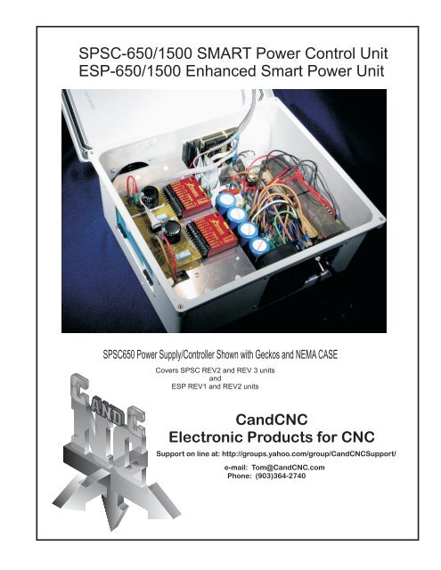
SPSC-650/1500 SMART Power Control Unit ESP-650 ... - CandCNC
SPSC-650/1500 SMART Power Control Unit ESP-650 ... - CandCNC
SPSC-650/1500 SMART Power Control Unit ESP-650 ... - CandCNC

You also want an ePaper? Increase the reach of your titles
YUMPU automatically turns print PDFs into web optimized ePapers that Google loves.
<strong>ESP</strong>-<strong>650</strong>/<strong>1500</strong> & <strong>SPSC</strong>-<strong>650</strong>/<strong>1500</strong> Smart <strong>Power</strong>3, 4 5 and 5.5 Axis Stepper and ServoTABLE OF CONTENTSUSERS MANUALTABLE of CONTENTSPAGE1 DESC2-6 Quick Start Instructions7. Block Cabling Schematic8. Block Operational Diagram9-12 HLC301 (I/O Card) Connections13. Gecko Mounting Plate Fastener Detail14. <strong>SPSC</strong> Main Board Overlay.15. <strong>ESP</strong> Main Board Overlay16. <strong>ESP</strong> Status/Fault Chart17. Rear Mounting Plate Drill Pat18. Dual Transformer <strong>650</strong> series Transformer Connections19. Single Transformer <strong>1500</strong> series Transformer Connections20. Transformer Connectors for 42V supply (<strong>650</strong> only)21. Transformer Connectors for 32V supply (<strong>650</strong> only)22. Transformer Connections for 220V single Phase (<strong>650</strong>)23. Bias Transformer Connections (all Models)24. Wiring Detail external AC power components25. FAN/FUSE/Breaker Detail26. Wiring Detail external AC components - 220V Single Phase.27. MTA100 to Main Board connection Detail28. MTA100 to Gecko EZPlug connection Detail29. Replacing a Motor Drive (step by step)30. Replacing a Motor Drive (cont)31. Exploded drawing of Gecko Plates and EZPlug32. Exploded drawing Triple Stack Plates (5 and 5.5 axis units)33. External board connections (Optional OP-1) <strong>SPSC</strong> Only34. MP1000 ACM cable detail (prior MP1000 owners)35. <strong>ESP</strong>/<strong>SPSC</strong> Mounting and Grounding Instructions.ADDENDUMSA-1 USDigital Encoder Specs for RouterPaks/PlazPaks ServosAll Content copyrighted 2008-2009 <strong>CandCNC</strong>No reproduction or redistribution is allowed without written permission.This manual and it’s images are for the use of <strong>CandCNC</strong> customers.TOC
MOTOR CONNECTION SETUP1. WITH THE <strong>SPSC</strong> UNIT in STOP MODE (RED STOP LED ON MP1000 is ON) .2. Plug one motor into the X axis connector (color coded RED) on the end of the <strong>SPSC</strong> <strong>Power</strong> CONTROLLER.3. IF you are using Servo motors there will be a short "Pigtail" for the Encoders at the motor (they are packagedseparately). Pick one motor and plug in one of the pigtails. Use a Standard Ethernet (UTP) cable to make theconnection from the end of the pigtail to the matching RJ45 connector (in this case X) on the <strong>SPSC</strong> <strong>Power</strong><strong>Control</strong>ler.4. Activate the RUN button on the front of the MP1000 (not RUN in MACH!).5. IF your motor is a stepper it should "lock" meaning it becomes hard to turn by hand.6. If your motor is a servo it should also lock but it may hum or vibrate with no load. This is normal. If the motorstarts spinning check the encoder connections. If you have wired the motor yourself and the motor startsspinning when it should be locked, turn off power, and reverse the motor power leads in the connector.7. Once you have one axis with a locked motor you can STOP the controller (RED Button on MP1000) and plug inthe other motors in your package. All should come up and lock.At this point you have confirmed proper operation of the <strong>ESP</strong>/<strong>SPSC</strong> <strong>Power</strong> <strong>Control</strong>ler and the interconnect to theMP1000 from the <strong>ESP</strong>/<strong>SPSC</strong>.NOTE: The EPS and <strong>SPSC</strong> series of <strong>Power</strong> <strong>Control</strong>lers uses microprocessor control to control all aspects of thepower cycle. It uses a sophisticated Ultra Soft Start (appox 3 sec) that limits inrush current to levels that protectthe input components and upstream components in your AC source (breakers, plugs, wires). The power rampsup over the 3 seconds and full power is not at the Motors until softstart is finished. In Servo systems using ourEZPLug Servo interface (included in all Servo Package deals) the Gecko drives must go through a separateRESET Cycle. The EZPlug cards have special circuitry to make sure the Gecko's come up in RESET mode andthat the cycle is applied after Softstart. There is a total delay of approx 6 seconds from power up to the Geckoscoming out of RESET and being ready to run.At power up, the processor starts the softstart, engages the secondary Main <strong>Power</strong> Relay which applies ACpower to the transformer primary and turns on DC (over the softstart cysle) to the Drives. It monitors the voltageand current at all times and if either are not correct or out of tolerance the supply automatically shuts down. Thereaction is fast enough that if there is a short anywhere in the DC side of the power system the supply will noteven complete the Soft Start cycle.In a servo system the processor also monitors the individual fault signals from each Gecko Servo Drive. If, afterstartup a drive faults, the supply will instantly shutdown; often faster than the Fault LEDS will light. Prior totuning it's possible that starting a Gecko with a large servo might cause the drive to fault. IF you get constantimmediate shutdowns after 5 seconds you should suspect a drive is mistuned. Open the <strong>ESP</strong>/<strong>SPSC</strong> (WITHPOWER DISCONNECTED) and find the three adjustment pots on the End of the Geckos. You may have to removethe Nylon Screws holding the GEcko Mounting Plate in place and lift it to access the bottom drives. Turn eachCurrent limit to full and set each Gain and Dampening to midrange. You will probably have to retune them afterthe motors are mounted to the loads. NOTE: ALL Package deals purchased with motors are bench tested withthe actual motors you recieve and you should not have a problem with a fault causing premature shutdown.The rest of the setup consists of loading the software (MACH) in the PC. Loading profiles and connecting theMP1000 Interface to the PC. Please see those sections for continuing setup.Loading MACH: There is a version of MACH on the Support CD. It will be an older release. It will work but maynot have all of the latest features. The latest version will be on the www.MachSupport.com website. If youalready have a version of MACH loaded and it’s later than 2.00.10 then it should be good to use. IF YOU UPDATEYOUR VERSION OF MACH FROM A WORKING VERSION MAKE A COPY OF THE MACH3 FOLDER (rename andsave) FIRST. The default “profiles” loaded by MACH at install and displayed as ICONS on the desktop ARE NOTthe correct profiles for any of our equipment. After loading MACH delete all the desktop icons but the MACHLOADER. It is used to start MACH and allow you to select from multiple profiles.4
After MACH is installed you can license it by copying the license file (if sent from us it will be in an encryptedformat and has a unique serial number) into the MACH3 folder. That is all that is required. The LIC file cannotbe opened or extracted. To determine of your copy of MACH is licensed go to Help/About off the top menu.There should be a serial number in the file. We keep copies of all serial numbers and to what customer theyare issued. If you lose your license file you can contact us with and we will reissue.You will need to run the INSTALL.exe file off the CD (root directory). It will automatically install:All <strong>CandCNC</strong> MACH profiles (XML files)All <strong>CandCNC</strong> Custom MACH Screens (SET Files)All <strong>CandCNC</strong> Plug-insAll <strong>CandCNC</strong> Bitmaps for Screens (in MACH/Bitmaps/<strong>CandCNC</strong> Folder)Getting ready to runAt this point you should have the <strong>ESP</strong> or <strong>SPSC</strong> power controller Checked out for basic operation. It’s now timeto connect the components together and test the full system. You should do this on the bench prior tomounting the motors to the mechanical part s of the machine.1. With power off on all components connect the MP1000 series box via the 2 Parallel Port Cables (DB25 M-M).2. Connect the AXIO I/O Cable (DB25 M-M) from the back of the MP1000 to the side connector on the<strong>ESP</strong>/<strong>SPSC</strong> <strong>Power</strong> <strong>Control</strong> box (only 25 pin connector.3. Connect the HLC301 I/O card to the Back of the MP1000 into the slot marked TABLE I/O. (DB25 M-F),4. Leave the Serial cables disconnected for now.5. DO NOT CONNECT OR LOAD/CONFIGURE THE MPG101B Pendant yet.6. Boot the computer7. Follow the Parallel and serial port setups in the MP1000 Manual. Make sure the 2nd parallel port iscommunicating with MACH. Best test is to load the MP1000C-THC profile (even if you have the routerpackage) and press the UP or Down buttons on the HLC301 card. You should see the UP and DOWN on theProgram Run screen in MACH (with our screens and the MP1000C-THC profile running) respond to the buttons.If they do not, check to make sure the parallel port card is properly installed and you have the correct Hexaddress for Port2 in MACH. (NOTE: each profile you have, contains all of the settings including the Port 2address and details. If you change profiles (Selected from MACH Loader at startup) you will need to setup thecorrect address TO THAT PROFILE. The profiles also contain motor tuning, Home direction, Motor directionand axis information and will have to be changed/setup for that profile.8. Check your wiring against the Block Cabling Diagram on the next page. You should have all of the cablesconnected EXCEPT the serial cables or the Optional Hand <strong>Control</strong>ler and Quad Relay Box.9. Plug in the Motors (and encoder cables if it’s Servo). Turn on power to MP1000 box (rear switch). Turn on<strong>Power</strong> to <strong>ESP</strong>/<strong>SPSC</strong> <strong>Power</strong> <strong>Control</strong>ler via it’s main power switch.10. MP1000 MAY have some LED’s illuminated on the front panel (Step & Dir Monitor) but that is randomindications and should be ignored for now. The RED STOP light on the front of the MP1000 will be illuminated.The red power LED on the HLC310 will be illuminated.11. Make sure the correct Profile (Supplied by <strong>CandCNC</strong>) is loaded YOU CANNOT USE THE DEFAULT MILL ORPLASMA Profiles provided by MACH.12. Select the RUN Button in front of the MP1000 (This is MOTOR RUN, not Code Run in MACH) The RUNbutton in MACH runs code!13. RUN LED on MP1000 (Green) should be ON14. Select RESET button in MACH. Mach should come out of reset. CP LED on the MP1000 should light.15. Try using the (arrow keys) to Jog X. Don’t worry if the direction is wrong. If the motor rotatesand changes direction hit the SHIFT then the arrow key and you will get 100% of the default velocity.16. Check the other motors,If you do not get rotation:1. Check the DRO’s for the AXIS in MACH....are they changing when you attempt to jog.2. Did the motors “lock” when you pressed the RUN button on the MP1000?3. Do the Step and Dir LED’s on the front flash for the appropriate axis. Step LEDS Flash while DIR LED is onor off for DIRECTION. The important thing is they change when you jog or reverse direction.4. Is the CP lite on the MP1000 illuminated?5
MACH has a signal called “Charge Pump” it indicates MACH is in control of the computer. It prevents false triggeringof port outputs (possibly turning on Outputs) by keep any output off unit it sees the CP signal. On the MP1000C seriesthe CP signal comes in on Port 2 Pin 17. If you don’t get a CP l;ight when you come out of RESET in MACH it’spossible the Port 2 address is not correct of the card is not working right.If the Step & Dir LED’s are showing activity and the motor DC is on (motor is locked) then the signal is getting to theAXIS/IO cable at the back of the MP1000 but not getting to the Geckos.Turn off power and carefully check all of your cable connections, and all of the ribbon cable connections inside the<strong>ESP</strong>/<strong>SPSC</strong> <strong>Power</strong> <strong>Control</strong>ler Cabinet. The AXIS/IO cable connects directly to the MTA100 small distribution card. TheStep & Dir signals are cleaned (again) and amplified (again) and sent via the small 10 pin ribbon cables to the EZPlugGecko Interface cards. Check all those cables to make sure they are firmly seated.CHECKING FOR <strong>ESP</strong>/<strong>SPSC</strong> FAULT Detection (SERVO).1. Put <strong>ESP</strong>/<strong>SPSC</strong> <strong>Power</strong> <strong>Control</strong>ler in STOP Mode via the RED button on the front of the MP1000.2. Disconnect the X motor (You can leave the encoder connected.3. Put <strong>ESP</strong>/<strong>SPSC</strong> back into RUN from the MP10004. Jog the X axis (with no motor attached. The Gecko will fault and the <strong>Power</strong> <strong>Control</strong>lerwill turn off the motor DC.(RED STOP turns on)<strong>ESP</strong> Testing5. With the cabinet door open observe the row of LED’s. The GECKO Led will light if there is a servo fault (NOT activeon Steppers) and will flash the number of times to indicate which Gecko caused the fault.6. Anytime the power is shutdown the DC Load Dump Circuit goes active for 2 - 3 seconds. It’s activity is indicatedon the LD LED. It only comes on when the load dump circuit is active.SETTING UP COMMUNICATIONS BETWEEN MACH and the <strong>ESP</strong> Series1. With power off on all units (including PC) attached a 9 Pin straight through cable from the Serial port on the PCover to the PC COM plug on the <strong>ESP</strong><strong>650</strong>/<strong>1500</strong> unit.2. If you have an MP1000C-THC (Torch Height <strong>Control</strong>) or the MP1000-SPS (Spindle Speed) you will need to attach a9 pin cable from the MP1000 plug on the <strong>ESP</strong> control box over to the SERIAL plug on the back of the MP1000C. NOTE:NOT the SENSOR plug!) The Serial plug is the same row as the Port 1 and Port2 plugs on the back of the MP1000.10 Make sure your PC Serial port (see MP1000 manual for details) is setup and active.11. Open MACH and use the Config Plugins option to activate the CCC-COMBO plugin (used for both the <strong>ESP</strong> and/orthe MPG101B Pendant) .12. Make sure you have the MP1000C-<strong>ESP</strong>-### Screen set loaded. (### is for the type unit you are testing ; THC, SPSor Basic). It should have the <strong>SPSC</strong> Parameters section and DRO’s for Volts, Amps, Temp and the Fault message box.13. Turn on all of the components. If you have communication between the <strong>ESP</strong> unit and MACH you will see a valuein the TEMP DRO (unless it just happens to be zero degress inside the cabinet!).14. If you have a temp reading then hit the RUN on the MP1000 and activate the Motor DC. You should see a voltagereading of from 62 to 70 VDC and a samll amount of current.15 If you run the “Gecko Fault” test in step 5 it should give you a Fault message in the Fault Box at the bottom and tellyou which Gecko Faulted.16. As you run the motors (unloaded, you may see a small flicker on the Load Graph.. That indicates the percentageof load being supplied by the <strong>Power</strong> <strong>Control</strong>ler. While momentary 100% load conditions will not harm the unit if lessthan 20% duration, continuous operation at 100% will eventually cause problems.17. The unit is designed to shutdown if the inside temp gets too high (possible airflow problem) or if the volt orcurrent (load) goes to high. The appropriate LED in the unit will come on and if the MACH COM interface is active,show up on the screen.6
If you cannot get MACH to communicate with the <strong>ESP</strong> unit:1. Make sure the Serial Cables are straight through (NOT true serial cables). If they came from us they will becorrect.2. Open the Config Plugin in MACH and open the CONFIG section and move to the <strong>ESP</strong> menu. Open the door onthe <strong>ESP</strong> cabinet and with it powered up (Does not have to be in RUN Mode or have the MP1000 connected) pushthe screen COM Test button. You should see two quick flashes of three of the Fault LED’s. No flashes indicatethe plugin is not communicating out to the <strong>ESP</strong>. No numbers on screen for TEMP (and volts if in RUN mode)indicates the data is not getting from the <strong>ESP</strong> back to MACH.The serial communications between the MACH plug-in and the <strong>ESP</strong> are “multi-drop” based meaning there can bemultiple devices on the same serial line. The MP1000C-THC (and SPS) serial port will talk across the same serialconnection as the <strong>ESP</strong>. At this point the only thing the MP1000C uses serial for is to send Tip Volt settings (orRPM settings) to the MP1000 box. The MP1000C units receive ONLY.REAR PANEL FEATURESSingle 9 Pin Cable interface to the THCSensor CardORVFD Interface for Spindle SpeedSingle Cable interface to our uniqueHLC301 for easy access toTable limits and Relay outputsSingle Cable interface to remote<strong>Power</strong> Supply and Drive cabinet.4 full axis signals + power control*UNIT POWER SWITCHSENSORCARDTABLE I/OAXIS I/OON1 56 9SERIALPORT 2PORT 1110 - 125VAC1 Ph 60HZ only1 56 9Serial Port for advanced interchange withMACH3 and <strong>ESP</strong> <strong>Power</strong> <strong>Unit</strong>sBuffered out, Isolated in on two parallel ports6A
BLOCK CABLING SCHEMATICNOTE not to scale or positionSerial Port (PC)DB9 Straight ThroughSerial COM link to <strong>Power</strong> <strong>Control</strong>ler ONLY on <strong>ESP</strong>MODELSPORT1 (PC) PORT1PORT2 (PC)PORT2)MP1000HLC301 CardSerial (9 pin)AXIS I/O PLUG25 pinTABLE I/OPLUG25 PinNEW TABLE I/O Card<strong>ESP</strong>/<strong>SPSC</strong> POWER CONTROLLERENCLOSURESerial (PC COM 1)Serial (MP1000 Serial)POWER CONTROLLERMOUNTS ON or NEARTABLE/MOTORSMPG101 Hand<strong>Control</strong>ler(OPTION)QUAD RELAY BOX(OPTION)UP to 25’Table Swtiches(Homes, Limits, etc)Mount on Table or on <strong>SPSC</strong> EnclosureFor connection of MP1000C-THC (Torch Height <strong>Control</strong>) please refer to those manuals for the addedcabling and external cardsON Earlier <strong>SPSC</strong> models the serial cable is connected directly from the MP1000 serial port to the PC serial portDesktop orworkstationPCPC with 1 serialand 2 parallel ports7
GECKO INTERFACEEZPlug CardDual Stepperor Dual ServoGECKOTEMPSENSEINTERNALTEMPSENSESERIAL toPCLOGIC INTERFACES & D SIGNALSE_STOP FEEDBACK<strong>SPSC</strong> <strong>SMART</strong> CONTROLBLOCK DIAGRAMRUN/STOPMTA100MOTORDCAC to DC CONVERSIONTRANSFORMER(S)RECTIFIERSFILTER BANKAC CONTACTOR/RELAYLOAD DUMPDYNAMICBRAKINGVOLTAGESENSEOVPCURRENTSENSEELECTRONICFUSEPROCESSOR CONTROLMONITORING:OvervoltageOver loadOverTempGecko FaultSERIAL toMP1000FROMBUFFEREDINTERFACE(MP1000)AC INPUTELECTRONICSOFTSTARTOVERVOLTAGESHUTDOWNAC120VAC230VACSURGEPROTECTIONOPTIONALOPERATORPODRemoteReadout/<strong>Control</strong>8
0.020"5.580"5.060"0.000" 0.000"REMOTERELAYUP DWNEPO[ESTOP]NCFHOLDX HOME Y HOME Z HOME A HOME B HOMEJ5J4J18 J17 J16 J15 J14 J13 J12 J11PLUG5.258"J3TO Quad RelayPLUG116 91411ISOLATEDMACHINE INPUTSX HOME Y HOME Z HOME A HOME51111A HOMEDWNUPCANDCNCHLC301Z HOMEY HOMEX HOMETO MP1000PUSH BUTTONSTO TEST1PWRLIMITAUX 1HOME-LIMIT CARDD81325J20 J22 J23 J24 J25 J26 J27 J19AUX1FGND+12 +12TABLE I/OCABLEUse Normally Closed [NC]Jumper any UNUSEDLIMITSTypical Case cutout for surface mounting or rear mounting is 5” X 3”Screw terminals are mounted on back of card so wire connections areprotectedFROM TABLE I/OCONNECTORDB25 EXTENSIONCABLE15ft9
E-stop jumper is required for operation. It can be replaced with a Normally Closed switch to mounta local e-stop close to the table or controller cabinet.NOTE: This e-stop is a software e-stop to halt movement from the control software. It does NOTshut power off to the motors.REMOTERELAYUP DWNEPO[ESTOP]NCFHOLDX HOME Y HOME Z HOME A HOME B HOMEJ5J4J18 J17 J16 J15 J14 J13 J12 J11PLUGJ3TO Quad RelayPLUG116 91411ISOLATEDMACHINE INPUTSX HOME Y HOME Z HOME A HOME51111A HOMEDWNUPCANDCNCHLC301Z HOMEY HOMEX HOMETO MP1000PUSH BUTTONSTO TEST1LIMITPWRFROM TABLE I/OCONNECTORDB25 EXTENSIONCABLE15ftAUX 1HOME-LIMIT CARD2513D8J20 J22 J23 J24 J25 J26 J27 J19AUX1FGND+12 +12TABLE I/OCABLEUse Normally Closed [NC]Jumper any UNUSEDLIMITSAux floating +12 supply for use with powered (optical) type sensorsand switches Max current draw 150ma total.FGND is common (return) for +12All inputs are opto isolated. To test inputs the corresponding Test Button can be pressed. The associated LED should light andthe matching input in MACH should light. Buttons should not be activated while machine is running (except to test UP and DWN)Limit switches should be NORMALLY CLOSED. Home Switches and other inputs should be NORMALLY OPEN.10
111111Connection for using the UP and Down during cutting operations (for oxy-acet)Two Normally Open PushbuttonSwitchesUp to 25’awayREMOTERELAYUP DWNEPO[ESTOP]NCFHOLDX HOME Y HOME Z HOME A HOME B HOMEJ5J4J18 J17 J16 J15 J14 J13 J12 J11PLUGTO Quad Relay16 9ISOLATEDMACHINE INPUTSX HOME Y HOME Z HOME A HOME5UP and Down test buttons will simulatea hand controlA HOME DWNUPCANDCNCHLC301Z HOMEY HOMEX HOMEPUSH BUTTONSTO TEST1AUX 1LIMITPWRHOME-LIMIT CARDD8J20 J22 J23 J24 J25 J26 J27 J19AUX1FGND+12 +12Use Normally Closed [NC]Jumper any UNUSEDLIMITSTo use the UP and DWN while cutting manaully youmust check the “Allow THC UP-DOWN...” box inMACH configurationJ3PLUG114TO MP10002513TABLE I/OCABLE11
10Quad Relay CardBottom SideConnecting the HLC301 to the Quad Relay CardUse one method or the other but not BOTH!Connection Via Db9 cable (up to 25’)REMOTERELAYUP DWNEPO[ESTOP]NCFHOLDX HOME Y HOME Z HOME A HOME B HOMEK5+K2J435J17J1K5+K2J435On top of card (opposite side shown)10J1J2J17J2J5J4J18 J17 J16 J15 J14 J13 J12 J11PLUGJ3TO Quad RelayPLUG116 914OR11ISOLATEDMACHINE INPUTSX HOME Y HOME Z HOME A HOME51111A HOME DWNUPCANDCNCHLC301Z HOMEY HOMEX HOMETO MP1000PUSH BUTTONSTO TEST1AUX 1LIMITPWRFROM TABLE I/OCONNECTORDB25 EXTENSIONCABLE15ftHOME-LIMIT CARD2513D8J20 J22 J23 J24 J25 J26 J27 J19AUX1FGND+12 +12TABLE I/OCABLEUse Normally Closed [NC]Jumper any UNUSEDLIMITSConnection via 10 pin ribbon cable (within 10”)The Quad Relay Card can be connected to the HLC301 card up to 25 ft awayusing a 25ft Male to Female DB9 Extension cable. The card can be installed ina standard 4 x 4 x 2 molded plastic electrical box.It can also be mounted in the cabinet with the HLC301 card and connected viaa short (max length 10”) 10 pin ribbon cable.For Quad Relay Box connections just plug in the DB9 M-F extension cableAnd the AC cord from the box to power. To access the two aux low current relaysor the aux 12V power for using external SSR’s see page 712
To remove Gecko Mouning plate to access lower Gecko’s1. Lossen 4 nylon screws on top of plate2. Slide plate back from end cover3. Remove nylon screws4. Lift plateReassemble in opposite order.MOTOR GROUNDSCAUTION: Plate is insulated from main chassis and is at <strong>Power</strong> DC potential.ISO3MTA100Temp ProbeDo not handle CROSS CONNECTMOTOR POSor touch when unit is operating.J3K21220Always remount plate with nylon screws andJ4519U-1J35insulation tape to riser BANK2blocksU3OCP REMOTE PODJ24 J20 J23J46210J22 J21 J1919J37J47216BANK1GECKO MOUNTING SHELFU4115BASIC FRONT PANEL EECCSPSU-Q2 Q5J39MOTOR POSC17MOTOR GROUNDSMTR 4MTR 1MTR 5MTR 2MTR 6MTR 3REV2R17C12R12U2Q4Q3Q6++ D6 +~ + D8~ - ~U6~-1191J33C8DC GND 2+J26C9 DC VOLTS 1J32+DC GND 1DC VOLTS 2J36J9J14J12C11EPO-1A EPO-1B+JUMPERC10EPO-2AJ17JUMPER+EPO-2B+C23C24+J40Bias XMR Sec++++----+R3R4<strong>CandCNC</strong><strong>SMART</strong> POWER+~J11L1 AC INSwitch AJ15AC NEU AJ5+~K1D1C2C1R2R1J8AC INSAFETY GROUNDJ8~-J10Fuse AJ13Switch BL2 INF2F1~-K1FUSE B INJ7T2 SEC AT2 SEC BAC NEU A & BJ2 J18J1Bias Xmr AAUX AC AAC OutputsBias Xmr BAUX AC BCAUTION ! HIGH VOLTAGEJ38T1 SEC AJ34T2 SEC BT1 SEC BT1 & T2PRIMARYJ4CAUTION ! HIGH VOLTAGEQ1TOP TOPT1 & T2PRIMARYCONNECTto CHASSISJ31J30J16GG13
Older <strong>SPSC</strong><strong>650</strong>/<strong>1500</strong>Main baordNot Used onAllModelsComponents in YellowareAt Line potentialDO NOT TOUCHDO NOT CONNECT TestEquipmentCAUTION!Q1 Tab isAt AC linePotential!1191ISO3Temp ProbeJ3K2MTA100CROSS CONNECT1MOTOR POSU-120192J45J46J23MOTOR GROUNDSMTR 4J35BANK2U3OCP REMOTE PODMTR 6MTR 5Q610291J19J20J21J24J22J37U41615J47BANK1MTR 3MTR 2MTR 1CEC17E CQ5SPSU-MOTOR GROUNDS21BASIC FRONT PANELQ2REV2MOTOR POSJ39+~+ D8~+ D6C12R12R17~ - ~ -U2U6+Q3Q4J40C23C24+Bias XMR Sec+EPO-1A EPO-1B EPO-2A EPO-2BJ36J9J14J12J17J33DC GND 2J26DC VOLTS 1J32DC GND 1JUMPERJUMPERDC VOLTS 2++++C10C11C9C8+++++----R3R4R1K1J5C2J15AC NEU AJ11D1R2C1Mounted on back ofPCB~+Switch AL1 AC IN~+Mounted on back ofPCB<strong>CandCNC</strong><strong>SMART</strong> POWERFUSE B INT1 & T2PRIMARYL2 INJ13J8J10J7K1-Main AC RelayHeatsink onBack Plate~Heatsink onBack PlateAC INSAFETY GROUNDF1Switch BFuse A-~F2J8J1 J38J34GAC NEU A & BJ18J2Q1J4T1 & T2PRIMARYT2 SEC BJ16AUX AC BBias Xmr BAC OutputsJ30J31AUX AC ABias Xmr ACONNECTto CHASSISGCAUTION ! HIGH VOLTAGET1 SEC BT1 SEC ACAUTION ! HIGH VOLTAGET2 SEC A T2 SEC BUSE INSULATEDMOUNTING14
21112NEW <strong>ESP</strong> Smart <strong>Control</strong>ler OverlayAll Connections have remainded the same as the <strong>SPSC</strong> seriesSee next page for Status/Fault light display detailsComponents in YellowareAt Line potentialDO NOT TOUCHDO NOT CONNECT TestEquipmentCAUTION!Q1 Tab isAt AC linePotential!INJ40D2GTemp ProbePGMJ51J3C22 C28 C29C31J45J63 J52OP-1C32C27C302019321321MOTOR POSU7CROSS CONNECTMTA100J46ESIP2J35J47BANK2MTR 6MTR 5MTR 4211615D5K2SIP6J23Y1BASIC FRONT PANELJ19J20J21J24J22REG1J37MOTOR GROUNDS3.3VDCC41BANK1MTR 3MTR 2MTR 1GNDSPSU-REV10MOTOR POSSERIALBR20J41R17J25U4U9J29 C1712VDCC16~+ D6SERIAL AVR1R7Q3Bias XMR Sec-~~D8J17J14JUMPERJUMPERDC VOLTS 11201MTHoleEPO-2BEPO-1BC14J12J9DC GND 1Q4+EPO-2AEPO-1AJ32J26DC GND 2J33J36DC VOLTS 2U2++++VCCLDTEMP+ PWR Gecko +5FAULT----R3J5J15AC NEU AJ11ISO1K1Switch AL1 AC IN<strong>CandCNC</strong><strong>SMART</strong> POWERFUSE B INL2 INJ13J8T1 & T2PRIMARYJ10AC INSAFETY GROUNDF2F1Switch BFuse AJ8J7J34J38AC NEU A & BJ1J18J2J4T1 & T2PRIMARYT2 SEC BJ16AUX AC BBias Xmr BAC OutputsJ30J31AUX AC ABias Xmr ACONNECTto CHASSISCAUTION ! HIGH VOLTAGET1 SEC BT1 SEC ACAUTION ! HIGH VOLTAGET2 SEC A T2 SEC B* USE INSULATEDMOUNTINGNOTE: On some <strong>ESP</strong> version units the <strong>Power</strong> Switch (TRIAC) hasan insulated tab (mounting tab is not “hot” (connected to AC) andDOES NOT NEED an insulator or insulated (Nylon) Screw. IFYou unit does not have the insulator and nylon screw from theFactory DON’t PANIC! It’s the new type TRIAC.Not Used onAllModelsAC and Transformer Connections areallthe same as the earlier <strong>SPSC</strong> connectionsBoard mounts on same pattern15
<strong>ESP</strong> Status/Fault IndicatorsInitialization: Leds light from left to rightAll LED’s Flash twice: Response from MACHOffNo FaultPWRFAULTTEMPLDVCCGecko +5 +12Load DumpActiveGreen = OKSlow FlashOverVoltsBoardTemp++1/2 sec count flashnumber of 1/2 sec flashes ina group shows which GeckoFaulted. 1 flash = X 2=Y, etcFast FlashOverCurrent HeatsinkTempRestart/run clears Fault displayOff 1 secConstant Rapidflashing:Multiple GeckosFaulted<strong>ESP</strong>Board Fault Indicator<strong>CandCNC</strong>The chart above shows the <strong>ESP</strong> Status/Fault row of LEDS on the Main <strong>Control</strong> card.Initialization: Leds light from left to rightAll LED’s Flash twice: Response from MACHOffNo FaultPWRFAULTTEMPLDVCCGecko +5 +12Load DumpActiveGreen = OKSlow FlashOverVoltsBoardTemp++1/2 sec count flashnumber of 1/2 sec flashes ina group shows which GeckoFaulted. 1 flash = X 2=Y, etcFast FlashOverCurrent HeatsinkTempRestart/run clears Fault displayOff 1 secConstant Rapidflashing:Multiple GeckosFaulted<strong>ESP</strong>Board Fault Indicator<strong>CandCNC</strong>If your <strong>Power</strong> <strong>Control</strong> unit does not have a Decal for the LEDs in the cabinet, thencut one of those out and tape/glue it inside the case.16
Tap 10-32Drill -tap 6-32Main Plate Drilling Detail..201.154.24717.325
NoConnectNoConnectD2C2DCB2A2BATwin Transformer Setup- Normal <strong>650</strong> ConfigurationTransformer Connections for 60V operationAll 6 motor POS terminals at 60VDCMOTOR GROUNDSJ35J37J39MOTOR GROUNDSMTR 4MTR 1MOTOR POSMTR 5MTR 6J24 J20 J23J22 J21 J19MTR 2MTR 3MOTOR POSR17MTA100CROSS CONNECT2J45BANK2OCP REMOTE PODJ4621019BANK1SPSU-REV2R12J47216115BASIC FRONT PANEL EJ252019Q6CEQ2K2CQ5ISO3U-1C12Temp ProbeJ31C17+ ~U3U4+ D8~1191Q4Q3BANK2+U2U6J33C8DC GND 2+J26C9 DC VOLTS 1J32DC GND 1+DC VOLTS 2J36J9J14J12C11EPO-1A EPO-1B+JUMPERC10EPO-2AJ17JUMPER+EPO-2B+C23C24+J40Bias XMR SecNot Used onAllModels++++-~Mounted on back ofPCBHeatsink onBack Plate~L1 AC INFuse A-J13Switch BJ15AC NEU AL2 INJ5F1-~Mounted on back ofPCB~+Heatsink onBack Plate--R3R4<strong>CandCNC</strong><strong>SMART</strong> POWERJ8AC INSAFETY GROUNDJ8+-J11J10Switch AT1 & T2PRIMARYF2K1K1Main AC RelayD1C2R2C1J7R1FUSE B INComponents in YellowareAt Line potentialDO NOT TOUCHDO NOT CONNECT TestEquipmentCONNECTto CHASSISJ31T2 SEC AJ30T2 SEC BAC NEU A & BJ2 J18J1Bias Xmr AAUX AC AAC OutputsBias Xmr BAUX AC BJ16CAUTION ! HIGH VOLTAGEJ38T1 SEC AJ34T2 SEC BT1 SEC BT1 & T2PRIMARYJ4CAUTION ! HIGH VOLTAGEGQ1GUSE INSULATEDMOUNTINGCAUTION!Q1 Tab isAt AC linePotential!NOTE: Red and Black on each transformeris run in parallel. A connects to A2; B connects to B2C connects to C2 and D to D2. Strip and wrap the two wirestightly and use a single Quick Connect terminal for both wires.<strong>ESP</strong>-<strong>650</strong> <strong>SPSC</strong>-<strong>650</strong> Dual Transformer Version18
--<strong>ESP</strong>-<strong>1500</strong> <strong>SPSC</strong> <strong>1500</strong> Single Transformer (Dual Winding)All 6 motor POS terminals at 60VDCMOTOR GROUNDSJ35J37J39MOTOR GROUNDSMTR 4MTR 1MOTOR POSMTR 5MTR 6J24 J20 J23J22 J21 J19MTR 2MTR 3MOTOR POSR17MTA100CROSS CONNECT2J45BANK2OCP REMOTE PODJ46210BANK1SPSU-REV2R1219J47216115BASIC FRONT PANEL EJ252019CEQ2Q6K2CQ5ISO3U-1C12Temp ProbeJ31C17+ ~U3U4+ D8~1191Q4Q3BANK2+U2U6J33C8DC GND 2+J26C9 DC VOLTS 1J32DC GND 1+DC VOLTS 2J36J9J14J12C11EPO-1A EPO-1B+JUMPERC10EPO-2AJ17JUMPER+EPO-2B+C23C24+J40Bias XMR SecNot Used onAllModels++++-~Mounted on back ofPCBHeatsink onBack Plate~L1 AC INFuse A-J13Switch BJ15AC NEU AL2 INJ5F1-~Mounted on back ofPCB~+Heatsink onBack Plate-R3R4<strong>CandCNC</strong><strong>SMART</strong> POWERJ8AC INSAFETY GROUNDJ8+J11J10Switch AT1 & T2PRIMARYF2K1K1Main AC RelayD1C2R2C1J7R1FUSE B INComponents in YellowareAt Line potentialDO NOT TOUCHDO NOT CONNECT TestEquipmentCONNECTto CHASSISJ31T2 SEC AJ30T2 SEC BAC NEU A & BJ2 J18J1Bias Xmr AAUX AC AAC OutputsBias Xmr BAUX AC BJ16CAUTION ! HIGH VOLTAGEJ38T1 SEC AJ34T2 SEC BT1 SEC BT1 & T2PRIMARYJ4CAUTION ! HIGH VOLTAGEGQ1GUSE INSULATEDMOUNTINGCAUTION!Q1 Tab isAt AC linePotential!1.5KW Toroid19
NoConnectNoConnectD2C2DCB2A2BATransformer Connections for 42V 10A operationTwin Transformer SetupAll 6 motor POS terminals at 40VDCMOTOR GROUNDSJ35J37J39MOTOR GROUNDSMTR 4MTR 1MOTOR POSMTR 5MTR 6J24 J20 J23J22 J21 J19MTR 2MTR 3MOTOR POSR17MTA100CROSS CONNECT2J45BANK2OCP REMOTE PODJ4621019BANK1SPSU-REV2R12J47216115BASIC FRONT PANEL EJ252019Q6ECQ2K2CQ5ISO3U-1C12Temp ProbeJ31C17+ ~U3U4+ D8~1191Q4Q3BANK2+U2U6J33C8DC GND 2+J26C9 DC VOLTS 1J32DC GND 1+DC VOLTS 2J36J9J14J12C11EPO-1A EPO-1B+JUMPERC10EPO-2AJ17JUMPER+EPO-2B+C23C24+J40Bias XMR SecNot Used onAllModels++++-~Mounted on back ofPCBHeatsink onBack Plate~L1 AC INFuse A-J13Switch BJ15AC NEU AL2 INJ5F1-~Mounted on back ofPCB~+Heatsink onBack Plate--R3R4<strong>CandCNC</strong><strong>SMART</strong> POWERJ8AC INSAFETY GROUNDJ8+-J11J10Switch AT1 & T2PRIMARYF2K1K1Main AC RelayD1C2R2C1J7R1FUSE B INComponents in YellowareAt Line potentialDO NOT TOUCHDO NOT CONNECT TestEquipmentCONNECTto CHASSISJ31T2 SEC AJ30T2 SEC BAC NEU A & BJ2 J18J1Bias Xmr AAUX AC AAC OutputsBias Xmr BAUX AC BJ16CAUTION ! HIGH VOLTAGEJ38T1 SEC AJ34T2 SEC BT1 SEC BT1 & T2PRIMARYJ4CAUTION ! HIGH VOLTAGEGQ1GUSE INSULATEDMOUNTINGCAUTION!Q1 Tab isAt AC linePotential!NOTE: Red and Black on each transformeris run in parallel. A connects to A2; B connects to B2C connects to C2 and D to D2. Strip and wrap the two wirestightly and use a single Quick Connect terminal for both wires.20
NoConnectNoConnectD2C2DCB2A2BATransformer Connections for Twin 32V 10A operation20A totalMOTOR GROUNDSJ35J37J39MOTOR GROUNDSMTR 4MTR 1MOTOR POSMTR 5MTR 6J24 J20 J23J22 J21 J19MTR 2MTR 3MOTOR POSR17MTA100CROSS CONNECT2J45BANK2OCP REMOTE PODJ4621019BANK1SPSU-REV2R12J47216115BASIC FRONT PANEL EJ252019Q6CEQ2K2CQ5ISO3U-1C12Temp ProbeJ31C17+ ~U3U4+ D8~1191Q4Q3BANK2+U2U6J33C8DC GND 2+J26C9 DC VOLTS 1J32DC GND 1+DC VOLTS 2J36J9J14J12C11EPO-1A EPO-1B+JUMPERC10EPO-2AJ17JUMPER+EPO-2B+C23C24+J40Bias XMR SecNot Used onAllModels++++-~Mounted on back ofPCBHeatsink onBack Plate~L1 AC INFuse A-J13Switch BJ15AC NEU AL2 INJ5F1-~Mounted on back ofPCB~+Heatsink onBack Plate--R3R4<strong>CandCNC</strong><strong>SMART</strong> POWERJ8AC INSAFETY GROUNDJ8+-J11J10Switch AT1 & T2PRIMARYF2K1K1Main AC RelayD1C2R2C1J7R1FUSE B INComponents in YellowareAt Line potentialDO NOT TOUCHDO NOT CONNECT TestEquipmentCONNECTto CHASSISJ31T2 SEC AJ30T2 SEC BAC NEU A & BJ2 J18J1Bias Xmr AAUX AC AAC OutputsBias Xmr BAUX AC BJ16CAUTION ! HIGH VOLTAGEJ38T1 SEC AJ34T2 SEC BT1 SEC BT1 & T2PRIMARYJ4CAUTION ! HIGH VOLTAGEGQ1GUSE INSULATEDMOUNTINGCAUTION!Q1 Tab isAt AC linePotential!NOTE: Red and Black on each transformeris run in parallel. A connects to A2; B connects to B2C connects to C2 and D to D2. Strip and wrap the two wirestightly and use a single Quick Connect terminal for both wires.21
NoConnectNoConnectD2C2DCB2A2BAMOTOR GROUNDSJ35J37J39MOTOR GROUNDSMTR 4MTR 1MOTOR POSMTR 5MTR 6J24 J20 J23J22 J21 J19MTR 2MTR 3MOTOR POSR17MTA100CROSS CONNECT2J45BANK2OCP REMOTE PODJ4621019BANK1SPSU-REV2R12J47216115BASIC FRONT PANEL EJ252019Q6ECQ2K2CQ5ISO3U-1C12Temp ProbeJ31C17+ ~U3U4+ D8~1191Q4Q3BANK2+U2U6J33C8DC GND 2+J26C9 DC VOLTS 1J32DC GND 1+DC VOLTS 2J36J9J14J12C11EPO-1A EPO-1B+JUMPERC10EPO-2AJ17JUMPER+EPO-2B+C23C24+J40Bias XMR SecNot Used onAllModels++++-~Mounted on back ofPCBHeatsink onBack Plate~L1 AC INFuse A-J13Switch BJ15AC NEU AL2 INJ5F1-~Mounted on back ofPCB~+Heatsink onBack Plate--R3R4<strong>CandCNC</strong><strong>SMART</strong> POWERJ8AC INSAFETY GROUNDJ8+-J11J10Switch AT1 & T2PRIMARYF2K1K1Main AC RelayD1C2R2C1J7R1FUSE B INComponents in YellowareAt Line potentialDO NOT TOUCHDO NOT CONNECT TestEquipmentCONNECTto CHASSISJ31T2 SEC AJ30T2 SEC BAC NEU A & BJ2 J18J1Bias Xmr AAUX AC AAC OutputsBias Xmr BAUX AC BJ16CAUTION ! HIGH VOLTAGEJ38T1 SEC AJ34T2 SEC BT1 SEC BT1 & T2PRIMARYJ4CAUTION ! HIGH VOLTAGEGQ1GUSE INSULATEDMOUNTINGCAUTION!Q1 Tab isAt AC linePotential!Primaries Connected for 230-240 OperationThe PSC<strong>650</strong> can be used with two wire 220V circuits for non-US operationSpecial modifications at the factory must be made to operate the bias transformerfrom 220VAC. If 50HZ operation is required the main transformerswill need to be replaced with ones that are rated for 50HZ operation.Contact the factory to get ratings and information on use with 220V 50HZOperation. DO NOT ATTEMPT TO MAKE THE MODIFICATIONS WITHOUT FIRST GETTINGINSTRUCTIONS FROM THE FACTORY!230 VAC operation requires a single phase circuit with a Neutral wire(110 either side of neutral) Or the bias transformer needs to be changed22
Bias Transformer ConnectionsMOTOR GROUNDSJ35J37J39MOTOR GROUNDSMTR 4MTR 1MOTOR POSMTR 5MTR 6J24 J20 J23J22 J21 J19MTR 2MTR 3MOTOR POSR17MTA100CROSS CONNECT2J45BANK2OCP REMOTE PODJ4621019BANK1SPSU-REV2R12J47216115BASIC FRONT PANEL EJ252019Q6ECQ2K2CQ5ISO3U-1C12Temp ProbeJ31C17+ ~U3U4+ D8~1191Not Used onAllModelsQ4Q3BANK2+U2U6J33C8DC GND 2+J26C9 DC VOLTS 1J32DC GND 1+DC VOLTS 2J36J9J14J12C11EPO-1A EPO-1B+JUMPERC10EPO-2AJ17JUMPER+EPO-2B+C23C24+J40Bias XMR Sec++++-~Mounted on back ofPCBHeatsink onBack Plate~L1 AC INFuse A-J13Switch BJ15AC NEU AL2 INJ5F1-~Mounted on back ofPCB~+Heatsink onBack Plate--R3R4<strong>CandCNC</strong><strong>SMART</strong> POWERJ8AC INSAFETY GROUNDJ8+-J11J10Switch AT1 & T2PRIMARYF2K1K1Main AC RelayD1C2R2C1J7R1FUSE B INComponents in YellowareAt Line potentialDO NOT TOUCHDO NOT CONNECT TestEquipmentCONNECTto CHASSISJ31T2 SEC AJ30T2 SEC BAC NEU A & BJ2 J18J1Bias Xmr AAUX AC AAC OutputsBias Xmr BAUX AC BJ16CAUTION ! HIGH VOLTAGEJ38T1 SEC AJ34T2 SEC BT1 SEC BT1 & T2PRIMARYJ4CAUTION ! HIGH VOLTAGEGQ1GUSE INSULATEDMOUNTINGCAUTION!Q1 Tab isAt AC linePotential!N23
212219EE CC1Wiring Detail External AC <strong>Power</strong> ComponentsP1L1 HotSafety GNDL2 NeuNOTE: EPO1A & EPO1B must be jumpered andEPO2A & EPO2B must be jumpered.An extenal Kill Switch (NC) can be used in place of a jumper1191Temp ProbeJ3U3U4C17ISO3MTA100CROSS CONNECTK22019U-1MOTOR POSJ45OCP REMOTE PODJ4610BANK2J23J19J47BANK1MTR 5MTR 6Q6J24 J20J22 J211615BASIC FRONT PANELMTR 2MTR 3MOTOR GROUNDSMTR 1 MTR 4SPSU-J35J37J39MOTOR GROUNDSQ2 Q5C12REV2MOTOR POS+ ~ + D8~J25R12R17U2U6+BANK2Q3Q4J40C23C24EPO-2B +EPO-1A EPO-1B EPO-2ABias XMR Sec+J36J9J14J12J17J33DC GND 2J26DC VOLTS 1J32DC GND 1JUMPERJUMPERDC VOLTS 2++++C10C11C8C9++++----R3R4R1K1J5C2J15AC NEU AJ11D1R2C1Mounted on back ofPCB~+Switch AL1 AC IN~+Mounted on back ofPCB<strong>CandCNC</strong><strong>SMART</strong> POWERFUSE B INT1 & T2PRIMARYL2 INJ13J8J10J7K1-Main AC RelayHeatsink onBack Plate~Heatsink onBack PlateAC INSAFETY GROUNDF1Switch BFuse A-~F2J8AC NEU A & BJ1 J38J34GJ18J2Q1J4T1 & T2PRIMARYJ30J31T2 SEC BJ16AUX AC BAC OutputsBias Xmr BAUX AC ABias Xmr ACONNECTto CHASSISGCAUTION ! HIGH VOLTAGET1 SEC BT1 SEC ACAUTION ! HIGH VOLTAGET2 SEC A T2 SEC BJumper between AC Neutral andL2 AC In is required for 120VACOperation. See next page for 230VACInputs.Panel (Main) SwitchS2Panel (Main) Fuse Holder[15A Breaker in packagedunits]24
FAN/FUSE KIT (Included with Packaged <strong>Control</strong>ler Deals andEnclosure KitsNOTE: FAN/FUSE Kit consists of 120VAC high volume fan,15A AC breaker, Main <strong>Power</strong> Switch, line cord, and terminaedwires25
212219EC EC1Wiring Detail External AC <strong>Power</strong> ComponentsOperation on 220VAC Single Phase CurrentNote: Bias transformer MUST be changed for 220 V operation (non-USA)P1Plug for 220 VACL1 HotSafety GNDL2 NeuNOTE: EPO1A & EPO1B must be jumpered andEPO2A & EPO2B must be jumpered.An external Kill Switch (NC) can be used in place of a jumper.Large RED button on Package <strong>Unit</strong>s shuts power off instantly1191Temp ProbeJ3U3U4C17ISO3MTA100CROSS CONNECTK22019U-1MOTOR POSJ45OCP REMOTE PODJ4610BANK2J23J19J47BANK1MTR 5MTR 6Q6J24 J20J22 J211615BASIC FRONT PANELMTR 2MTR 3MOTOR GROUNDSMTR 1 MTR 4SPSU-J35J37J39MOTOR GROUNDSQ2 Q5C12REV2MOTOR POS+ ~ + D8~J25R12R17U2U6+BANK2Q3Q4J40C23C24EPO-2B +EPO-1A EPO-1B EPO-2ABias XMR Sec+J36J9J14J12J17J33DC GND 2J26DC VOLTS 1J32DC GND 1JUMPERJUMPERDC VOLTS 2++++C10C11C8C9++++----R3R4R1K1J5C2J15AC NEU AJ11D1R2C1Mounted on back ofPCB~+Switch AL1 AC IN~+Mounted on back ofPCB<strong>CandCNC</strong><strong>SMART</strong> POWERFUSE B INT1 & T2PRIMARYL2 INJ13J8J10J7K1-Main AC RelayHeatsink onBack Plate~Heatsink onBack PlateAC INSAFETY GROUNDF1Switch BFuse A-~F2J8AC NEU A & BJ1 J38J34GJ18J2Q1J4T1 & T2PRIMARYJ30J31T2 SEC BJ16AUX AC BAC OutputsBias Xmr BAUX AC ABias Xmr ACONNECTto CHASSISGCAUTION ! HIGH VOLTAGET1 SEC BT1 SEC ACAUTION ! HIGH VOLTAGET2 SEC A T2 SEC BPanel (Main) Fuse Holder[15A Breaker in packagedunits]230VAC (USA) connection.Requires 3 wire with AC NeutralNeutral (Grey wirein drawing) is connectedas shown. Jumper between AC Neutral andAC L2In is REMOVEDPanel (Main) SwitchS226
GND+5+5212219EE11191Temp ProbeJ3U3U4C17ISO3K2U-1CQ5C12MTA100CROSS CONNECT2019MOTOR POSJ45OCP REMOTE PODJ4610BANK2J23J19J47BANK1MTR 5MTR 6Q6J24 J20J22 J21MOTOR GROUNDSMTR 1 MTR 4C1615BASIC FRONT PANELMTR 2MTR 3SPSU-J35J37J39MOTOR GROUNDSQ2REV2MOTOR POS+ ~ + D8~J25R12R17U2U6+BANK2Q3Q4J40C23C24Bias XMR Sec+EPO-2B +EPO-1A EPO-1B EPO-2AJ36J9J14J12J17J33DC GND 2J26DC VOLTS 1J32DC GND 1JUMPERJUMPERDC VOLTS 2++++C10C11C9C8++++----R3R4R1K1J5C2J15AC NEU AJ11D1R2C1Mounted on back ofPCB~+Switch AL1 AC IN~+Mounted on back ofPCB<strong>CandCNC</strong><strong>SMART</strong> POWERFUSE B INT1 & T2PRIMARYL2 INJ13J8J10J7K1-Main AC RelayHeatsink onBack Plate~Heatsink onBack PlateAC INSAFETY GROUNDF1Switch BFuse A-~F2J8AC NEU A & BJ1 J38J34GJ18J2T1 & T2PRIMARYJ30J31Q1J4T2 SEC BJ16AUX AC BAC OutputsBias Xmr BAUX AC ABias Xmr ACONNECTto CHASSISGCAUTION ! HIGH VOLTAGET1 SEC BT1 SEC ACAUTION ! HIGH VOLTAGET2 SEC A T2 SEC BSTEPSTEPDirSTEPDirSTEPDirDirJ25 J24 J23 J22 J21 J20 J18A Z Y XB - Y'(TOP) (BOT)Z - AX - YJ221109J552102101919J55J345V SourceJ1J4 Encoder V11J6J5Drive CommonJ311+5J8J7Remote ShutdownGNDPC +5PC GNDRS2019D3S&D CARDD6219D510EXT Port<strong>CandCNC</strong>MULTI-AXIS INTERFACEREV1<strong>SPSC</strong> InterfaceD4J19U5J52D2J9C1D121AXIS I/O INJ50MINI-IO IN1Cross connect (25 pin ribbon cable) to MTA100 Card27
21C1J9To <strong>SPSC</strong> Main <strong>Control</strong>lerCard via 26 pin ribbon cable2019DirSTEPDirSTEPDirSTEPDirSTEP8181TO MP1000 B or C seriesInterface <strong>Unit</strong> via DB25cableJ2<strong>SPSC</strong> InterfaceJ3GNDDrive Common21+510D2D1J50 AXIS I/O INJ1921019S&D CARD115V SourceEncoder V1 J4 Encoder 1J1J34D3D6D5D4PC +5PC GNDJ5J6J8 RSJ7Remote ShutdownJ52 MINI-IO INJ5521021091919J55U5Make sure all 12 screwterminals are tightened12J121J1109From <strong>Power</strong> SupplyHigh CurrentNOTE POLARITYof CONNECTIONS!Reversed powerblows Geckos!!C3C4GECKO 320orGECKO 340J53<strong>CandCNC</strong>DUAL GECKOINTERFACEREV 0R16MTR DC +D11MTR DC NEGSERVO 2J22J4Motor negMotor negMotor pos +Motor pos ++470 @ 250J7J18ENCODER 21C1C5U1J2U2Q2U1EXT Port<strong>CandCNC</strong>MULTI-AXIS INTERFACEREV1X - YZ - A(TOP) (BOT)B - Y'1J25GNDJ24+5J23+5J22AJ21ZJ20YJ18XX-Y CableDiagram showing connection of MTA100 to EZplugGecko Interface card (one dual servo cardshown) MTA100 supports up to 3 EZplug cardsEZPlug Stepper Card (not shown) mounts and connectsthe same way with a single ribbon cable and 4 power wiresSee EZPlug Manual for more details-4-40 SHCS3 placesGECKO 320orGECKO 34012J54R3R4+Q4Q4470 @ 250Q3J99D9R2R5-R6DIODE_1D8D10DC NEGJ8J3MTR DC +RJ45SERVO 1J21J10J5ENCODER 1Motor negMotor negMotor pos +Motor pos +MOTORCONNECTORSMotor negMotor pos +1C2J20J19ALTNOTE POLARITYof CONNECTIONS!Reversed powerblows Geckos!!From <strong>Power</strong> SupplyHigh CurrentEach side of the motor connector hastwo conductors. You can connect asshown or use 4 wires (2X2 in parallel)terminated at the motor.28
REPLACING A MOTOR DRIVE Unplug AC cord to <strong>ESP</strong>/<strong>SPSC</strong> <strong>Unit</strong> Unplug all Motors and Encoder cables from end of <strong>Unit</strong> Loosen the 4 mounting screws from the Gecko Mouning Plate (Nylon) Unplug the 10 pin ribbon cable from the top EZPlug card Remove the heavy DC motor wires (two for each Axis) from the EZPlug Card. Remove the NYLON screws and keep them in a safe place...you cannot use metal screws Lift the plate assembly up to access the lower Geckos and EZplug Card Remove the 10 Pin ribbon cable from the lower EZPlug card. Remove the DC motor Wires (two for each axis) from the lower EZPlug Card. Remove the plate assembly from the cabinet. Remove the 4 screws that hold the separate plates together. Set aside the plate and Geckosyou do not need to change. Locate which Gecko you need to replace on the plate. For that Gecko you will need to first remove the EZPlug card. Remove the three 4/40 bolts holding the EZPlug card to the plate. Loosen all 12 screw terminals on BOTH Geckos attached to that card Slide EZPlug Card out of Gecko terminals On the Gecko you are replacing, lift up on the screw terminals. They plug onto posts on theedge of the gecko They will come off in groups of 3. This will expose the front mouningscrews. Loosen the front two mounting screws (do not completely remove them from the plate) Remove the two rear mounting screws. Remove the defective drive from the plate. Clean off any residual Thermal paste with alcohol and a rag. Put fresh thermal paste on the new drive bottom side. Remove the Screw terminals on the new drive (DO NOT PRY WITH A SCREW DRIVER!).Rocking them gently as you lift up helps. Slide the new drive onto the plate while holding the two front screws pushed up from thebottom. Slide the drive forward so the front mounting screws fit into the mounting slots on thedrive. Tighten the screws slightly; enough to keep them from spinning when you move thebottom nut (take out the slack) but leave them loose enough still be able to move the drive. Youcan tighten them using the bottom nut after they are adjusted Replace the rear screws and tighten enough to hold drive on the plate. They will be finaltighened after they are adjusted Plug the Screw Terminals back onto the drive. Loosen ALL 12 screw terminals on the new drive. Slide the EZPlug card back into place on the drives and align the mounting holes for the card. You can put the EZplug mounting screws back into place. Leave them loose Make sure the Gecko drive is pushed towards the EZPlug Card and is aligned parallel. Thereshould be less than 1/8 gap on the smaller pins to the Gecko screw terminals. Once you have things aligned carefully tighten the Gecko mounting screws down on eachcorner so that the Gecko mounted firmly against the plate in all 4 corners. A small amount ofThermal Paste may squeeze out. IMPORTANT: The Gecko Mounting plate acts as a highefficiency heatsink for the drives. In order for it to work properly and keep the internaltemperature of the drives below a damaging point the drives MUST be mounted with thermalpaste (compound) and mounted flat and tight against the plate.29
Tighten the 3 EZPlug screws Tighten ALL 12 screws terminals snugly down on the pins from the EZPlug card. Double check all of theterminals on both drives! Remount the two separate Gecko Plates to each other using the 4 short machine screws. Place the assembly back in the cabinet and reattach the 10 pin ribbon cable and DC motor power wires .Be careful to get the polarity correct on the DC motor wires. If you hook it up wrong the power controllerwill shutdown instantly when you try to start it (later). The slots in the Gecko Plates are for passing the ribbon and DC power wires. Use them to route the DCPoser wires up to the upper Gecko plate and the 10 pin ribbon cable from the MTA100 down to the lowerEZplug card. Place the Plate assembly on top of the riser blocks. Make sure the insulation tape is intact on the top ofthe riser blocks. Shove the plate towards the end of the cabinet so the motor connectors protrude. Alignthe slot screw tabs with the mouning holes in the plate and start the nylon screws into place. Avoid forcingthe screws and damaging the threads. It helps to first visually slide the slot tabs and then use a smallscrew driver to properly align the screw holes. Once the 4 screws are all started and the EZplug cards are engaged with the Cabinet End plate thentighten the 4 Nylon Screws. Do not over tighten. The Nylon Screws will strip out if you use too muchtorque. Check all the other cabinet wiring (especially the Front panel E-stop/Panic button. If it is loose from theEPO terminals on the board or the switch is stuck ON (open) the power supply WILL NOT START THE DC tothe drives! Close the cabinet and plug unit back into AC. With the motors still disconnected perform and inital testand outlined in the Quick Start section (page 2-3 of this manual). Reconnect motors and encoders and run motor testing.30
1010109C3Gecko EZPlug Interface cards (option on non packaged units) with optionalGecko mounting plateSERVO 2Valid Gecko Stepper Models;201, 202, 203,210, 212Valid Gecko Servo Models:320, 340J121K<strong>CandCNC</strong>DUAL GECKOR1INTERFACEREV 0+470 @ 250C1EZPlug Servo Card ShownEZPlug Stepper card mounts same waySERVO 2#6-32 X 1/4 ScrewsCable Access Holes#4 Threaded Standoffs (3)For EZPlug Gecko Interface CardUPPER PLATE1J54100K12#6 Threaded X 5/16”Standoffs+C2LOWER PLATEGECKO GECKO#4-40 X 3/8 Screws (8)Z Axis Gecko31
IMPORTANT: TRIPLE stack plates will NOT fit into smaller <strong>650</strong> case. You must use the larger <strong>1500</strong> case evenfor stepper systems to get 5 or six axis operationGECKO GECKOUPPER PLATEGECKOMIDDLE PLATELOWER PLATEEXPLODED VIEW GECKO TRIPLE STACK MOUNING PALTES32
NOTE New <strong>ESP</strong> Series card has connection for OP-1 but it’s not activated. All informationfor <strong>Power</strong> <strong>Control</strong>ler is displayed on Board level LED’s (faults) and/or on screen in MACHMOTOR GROUNDSJ35J37J39MOTOR GROUNDSMTR 4MTR 1J24J22A AMPSF TEMPH HISTORYMOTOR POSMTR 5MTR 2R17J20J21MTR 6MTR 3MOTOR POSJ23J19BANK2BANK1SPSU-REV2<strong>SPSC</strong> OPERATOR PODR12J4721J452MTA100CROSS CONNECTOCP REMOTE PODJ462101AC VOLTSLOAD METERBASIC FRONT PANELJ2591615+12 VOLTSVOLTS TEMP X Y Z A BAMPSDRIVE FAULTSFAULT DISPLAYEQ22019Q6ECQ5K2VIEWDB9 Connector (Male) for usewith OPTIONAL OP-1Operator PodCSTOPRUNVOLTSAMPSTEMP1TEMP2HOLD forHISTORYShows conditions at FAULTISO3U-1C12OPTIONAL OP-1Displays system parameters and faultsActive load meterHistory displayRun & Stop for motor volts1+THIS PAGE OBSOLETEThe <strong>SPSC</strong><strong>650</strong> can be controlled from OP-1,The auxillary panel (not included with any unitTemp ProbeJ3C17~shipped with MP1000) or from the front of theMP1000 units. Make sure you swap theU3U4+ D8Cable (ACM) inside the MP1000 as outlinedon the next page~1191Q4Q3BANK2+U2U6J33C8DC GND 2+J26C9 DC VOLTS 1J32DC GND 1+DC VOLTS 2J36J9J14J12C11EPO-1A EPO-1B+JUMPERC10EPO-2AJ17JUMPER+5VDC RUN+EPO-2B+C23C24+J40STOPBias XMR Sec+++RUN/STOP Panel for local testing or control+<strong>CandCNC</strong><strong>SMART</strong> POWERJ8AC INSAFETY GROUNDJ8-+~Mounted on back ofPCBHeatsink onBack Plate~-J11L1 AC INJ10Fuse A-Switch AJ13Switch BJ15AC NEU AL2 INJ5T1 & T2PRIMARYF1-F2~Mounted on back ofPCB~+Heatsink onBack Plate--K1Center Switch R3 not usedR4K1R1C2D1Main AC RelayR2C1FUSE B INJ7CONNECTto CHASSISJ31T2 SEC AJ30T2 SEC BAC NEU A & BJ2 J18J1Bias Xmr AAUX AC AAC OutputsBias Xmr BAUX AC BJ16CAUTION ! HIGH VOLTAGEJ38T1 SEC AJ34T2 SEC BT1 SEC BT1 & T2PRIMARYJ4CAUTION ! HIGH VOLTAGEGQ1G33
Gnd5VThis page for persons buying <strong>ESP</strong> or <strong>SPSC</strong> AFTER buying aseparate MP1000 product or owning one previously. TheRouterPaks and PlazPaks that include the MP1000 will beconfigured properly and do not need this step!View Inside MP1000 <strong>Unit</strong> with top cover removedREAR PANELPanels shown out of case for clearityAXIS I/OTABLE I/OTHC / SPINDLE I/OJ41PORT12513J10PORT2SERIAL/RS232D6J6<strong>Power</strong> LEDAXIS-IOAXIS I/OJ72 10J52ACM-A1 9 1Pin 1 Pin 1ACM-BFor use with ALL <strong>ESP</strong> and <strong>SPSC</strong> move thisCable from ACM-B to ACM-APin 1J3109C&CNCMP1000-MBPOWERMPG/Switch inputsPin 191012MPGJ11920Front Panel InterfaceFRONT PANEL21Table I/O CardConnected to DB9on Front panelACMCABLETo route the STOP and RUN Switches and LED’s to port input pinsplug ACM cable into ACM-B as shown.To Use STOP and RUN switches and indicators to control theOptional ACM-100 or ACM-01 products plug ACM cable into ACM-ATHC is upper socketSpindle Speed lower (not used)See next pageFront Panel InterfaceSTOPFRONT PANELRUNThe function of the three bottom front panel switches is determined by the position of the ACM cable. When plugged intothe ACM-A Socket on the MP1000-MB the <strong>Unit</strong> is setup to control and indicate a remote optional ACM-100 or PSC<strong>650</strong><strong>Control</strong> Module. If you are using the MP1000 with an ACM or PSC<strong>650</strong> option the ACM Cable should be plugged into theACM-A socket.MPG/Switch inputsThe function of the front panel switches and indicators change when not used with an ACM <strong>Power</strong> <strong>Control</strong> Module. Withthe cable plugged into ACM-B (factory default) the switches are connected to input pins for MACH3 and have the34
DO: Make sure you run your PC and <strong>Power</strong> <strong>Control</strong> Box from a separate AC feed. Not fromthe router motor /VFD/plasma units AC feed. Make sure you have the AC to your PC and <strong>Power</strong> <strong>Control</strong> Box connected through asafety ground. Make sure the rear plate inside the <strong>ESP</strong> or <strong>SPSC</strong> <strong>Control</strong> box (large rearaluminum plate) is grounded to the safety ground wire of the power cord. Turn on your PC and load the control program (MACH) BEFORE you power up theMP1000 and <strong>ESP</strong>/<strong>SPSC</strong> boxes OR you have the Charge Pump Safety Circuit active(default setting on our units) so outputs will not accidently turn on when the computer isbooting. Use the supplied mounting tabs to mount the NEMA fiberglas case to any conductivesurface. Mount the cabinet away from possible moisture and coolant overspray Do not place hands or tools inside the cabinet when it is turned on. Even with the powerswitch turned off (Main <strong>Power</strong>) there are potentially lethal voltages in the AC section. ifyou need to work inside the cabinet unplug it first. If you need to work in the low voltagesection with the drives (tuning, etc) only power the unit after the AC you have thecomponents exposed and away from the AC section. NEVER place both hands inside thecabinet or touch any metal parts with more than one hand. If you are not qualified to work around live AC circuits, do not attempt to work on theunit. Use common sense around CNC equipment. A CNC machine does not know thedifference between wood/metal and flesh BE CAREFUL!! Mount additional Panic buttons at other locations around a larger machine.DO NOT: Tie the rear aluminum plate to ANY OTHER GROUND OR THE TABLE/MACHINEGROUND. Any noise on the table ground (especially Plasma) will conduct into the controlbox and may effect the control electronics. The ONLY ground to that plate should be viathe single AC safety ground (green wire) feeding the controller.Use the same AC feed (run from the main breaker) to run the <strong>ESP</strong>/<strong>SPSC</strong> <strong>Control</strong>ler andany table mounted device (Router motor, VFD, Spindle Drive, Plasma Torch, etc) Unplug encoder wires on servo systems with DC <strong>Power</strong> (RUN condition) to the motors.35
USDigital E5S Encoders Usedwith RouterPaks and PlazpaksServo motorsADDENDUM A-1E-option:Absolute Maximum Ratings:Parameter Max. <strong>Unit</strong>sVibration (5 to 2kHz) 20 gShaft Axial Play ±0.01 in.Shaft Eccentricity Plus Radial Play 0.004 in.Acceleration 250,000 rad/sec 2 Note that radial play translates directly to position inaccuracy.The E-option provides a cylindrical extention to the cover allowing for longershafts of up to .750".G-option:PolycarbonateSingle-ended (E5S)E5Optical Kit EncoderThis option includes molded ears on the E5 base which enable it to be mountedto a 1.812" diameter bolt circle. The mounting holes are designed to fit 4-40screws. Because the ears are molded to the E5 base this does not increasethe thickness of the encoder and does not add to the required shaft length.This option will work with shaft lengths of .445" to .570"Standard Single-ended Mechanical Drawing (E5S):E5S 500 250 EGVersion:S = Polycarbonate single-ended.D = Polycarbonate differential.MS = Metal single-ended.MD = Metal differential.CPR Notes:* Index option not available.** 32, 720, 900, 1250 CPRonly available with index.CPR:32**5096100110*120*192200250256360400500512540*720**900**10001016*10241250**Shaft Diameter:Code Size079 2mm118 3mm125 1/8"156 5/32"157 4mm187 3/16"197 5mm237 6mm250 1/4"312 5/16"315 8mm375 3/8"394 10mmOptions: (specificy in order shown)I = Index (3rd channel).L = Avago / Agilent / HP compatible pin-out. †E = Adds an extension to cover.H = Adds hole in cover.A = Adds self-aligning shoulder to base.3 = Changes diameter of all five basemounting holes to .125".A3 = Adds self-aligning shoulder to baseand changes diameter of all five basemounting holes up to .125".G = Adds 1.812 mounting "ears" to base.R = Adds 3-slot adapter to bottom of base. ††T = Adds transfer adhesive to base. ††Options Notes:†Only available with differential versions (E5D and E5MD).††Only available with polycarbonate versions (E5D and E5S). Acentering tool is highly recommended when using the T-option.36