I R 1 2 3 4 5 6 7 8 9 10 11 12 13 T 14 15 A - SDP/SI
I R 1 2 3 4 5 6 7 8 9 10 11 12 13 T 14 15 A - SDP/SI
I R 1 2 3 4 5 6 7 8 9 10 11 12 13 T 14 15 A - SDP/SI

Create successful ePaper yourself
Turn your PDF publications into a flip-book with our unique Google optimized e-Paper software.
ELEMENTS OF METRIC GEAR TECHNOLOGY<br />
I<br />
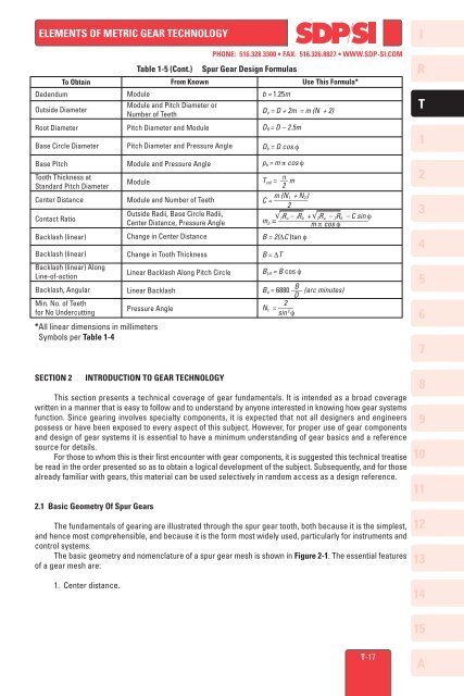
To Obtain<br />
Dedendum<br />
Outside Diameter<br />
Root Diameter<br />
Base Circle Diameter<br />
Table 1-5 (Cont.)<br />
Module<br />
From Known<br />
Module and Pitch Diameter or<br />
Number of Teeth<br />
Pitch Diameter and Module<br />
Pitch Diameter and Pressure Angle<br />
PHONE: 516.328.3300 • FAX: 516.326.8827 • WWW.<strong>SDP</strong>-<strong>SI</strong>.COM<br />
Spur Gear Design Formulas<br />
b = 1.25m<br />
Use This Formula*<br />
D o = D + 2m = m (N + 2)<br />
D R = D – 2.5m<br />
D b = D cos f<br />
R<br />
T<br />
1<br />
Base Pitch<br />
Tooth Thickness at<br />
Standard Pitch Diameter<br />
Center Distance<br />
Contact Ratio<br />
Backlash (linear)<br />
Backlash (linear)<br />
Backlash (linear) Along<br />
Line-of-action<br />
Backlash, Angular<br />
Min. No. of Teeth<br />
for No Undercutting<br />
*All linear dimensions in millimeters<br />
Symbols per Table 1-4<br />
Module and Pressure Angle<br />
Module<br />
Module and Number of Teeth<br />
Outside Radii, Base Circle Radii,<br />
Center Distance, Pressure Angle<br />
Change in Center Distance<br />
Change in Tooth Thickness<br />
Linear Backlash Along Pitch Circle<br />
Linear Backlash<br />
Pressure Angle<br />
p b = m p cos f<br />
T<br />
p<br />
std = –– m<br />
2<br />
m (N 1 + N<br />
C = –––––––––<br />
) 2<br />
2<br />
√ 1 R o – 1 R b + √ 2 R o – 2 R b – C sin f<br />
m p = ––––––––––––––––––––––––<br />
m p cos f<br />
B = 2(DC )tan f<br />
B = DT<br />
B LA = B cos f<br />
B<br />
B<br />
a = 6880 ––– (arc minutes)<br />
D<br />
2<br />
N c = ––––<br />
sin 2 f<br />
2<br />
3<br />
4<br />
5<br />
6<br />
7<br />
SECTION 2<br />
INTRODUCTION TO GEAR TECHNOLOGY<br />
This section presents a technical coverage of gear fundamentals. It is intended as a broad coverage<br />
written in a manner that is easy to follow and to understand by anyone interested in knowing how gear systems<br />
function. Since gearing involves specialty components, it is expected that not all designers and engineers<br />
possess or have been exposed to every aspect of this subject. However, for proper use of gear components<br />
and design of gear systems it is essential to have a minimum understanding of gear basics and a reference<br />
source for details.<br />
For those to whom this is their first encounter with gear components, it is suggested this technical treatise<br />
be read in the order presented so as to obtain a logical development of the subject. Subsequently, and for those<br />
already familiar with gears, this material can be used selectively in random access as a design reference.<br />
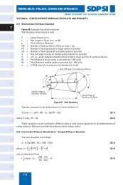
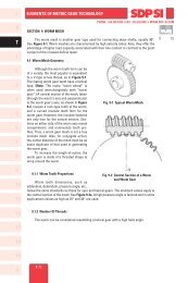
2.1 Basic Geometry Of Spur Gears<br />
The fundamentals of gearing are illustrated through the spur gear tooth, both because it is the simplest,<br />
and hence most comprehensible, and because it is the form most widely used, particularly for instruments and<br />
control systems.<br />
The basic geometry and nomenclature of a spur gear mesh is shown in Figure 2-1. The essential features<br />
of a gear mesh are:<br />
8<br />
9<br />
<strong>10</strong><br />
<strong>11</strong><br />
<strong>12</strong><br />
<strong>13</strong><br />
1. Center distance.<br />
<strong>14</strong><br />
<strong>15</strong><br />
T-17<br />
A