I R 1 2 3 4 5 6 7 8 9 10 11 12 13 T 14 15 A - SDP/SI
I R 1 2 3 4 5 6 7 8 9 10 11 12 13 T 14 15 A - SDP/SI
I R 1 2 3 4 5 6 7 8 9 10 11 12 13 T 14 15 A - SDP/SI

You also want an ePaper? Increase the reach of your titles
YUMPU automatically turns print PDFs into web optimized ePapers that Google loves.
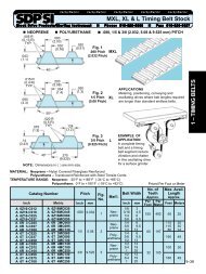
ELEMENTS OF METRIC GEAR TECHNOLOGY<br />
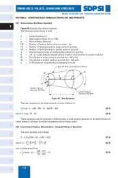
(b) Trochoid Interference<br />
PHONE: 516.328.3300 • FAX: 516.326.8827 • WWW.<strong>SDP</strong>-<strong>SI</strong>.COM<br />
This refers to an interference occurring at the addendum of the external gear and<br />
the dedendum of the internal gear during recess tooth action. It tends to happen when the<br />
difference between the numbers of teeth of the two gears is small. Equation (5-6) presents<br />
the condition for avoiding trochoidal interference.<br />
z<br />
θ 1<br />
1 ––– + inv α w<br />
z<br />
– inv α a2 ≥ θ 2 (5-6)<br />
2<br />
Here<br />
2 2<br />
r a2 – r a1 – a 2<br />
⎫<br />
θ 1 = cos –1 (––––––––––––) + inv α a1 – inv α w<br />
2ar a1<br />
⎪ ⎪⎬ (5-7)<br />
a 2 2 2<br />
+ r a2 – r a1 θ 2 = cos –1 (––––––––––)<br />
⎪<br />
2ar a2<br />
⎭<br />
where α a1 is the pressure angle of the spur gear tooth tip:<br />
d<br />
α b1<br />
a1 = cos –1 (–––) (5-8)<br />
d a1<br />
In the meshing of an external gear and a standard internal gear α = 20°, trochoid<br />
interference is avoided if the difference of the number of teeth, z 1 – z 2 , is larger than 9.<br />
(c) Trimming Interference<br />
This occurs in the radial direction in that it prevents pulling the gears apart. Thus, the<br />
mesh must be assembled by sliding the gears together with an axial motion. It tends to happen<br />
when the numbers of teeth of the two gears are very close. Equation (5-9) indicates how to<br />
prevent this type of interference.<br />
z<br />
q 2<br />
1 + inv α a1 – inv α w ≥ ––– (θ 2 + inv α a2 – inv α<br />
z w ) (5-9)<br />
1<br />
Here<br />
⎫ 1 – (cos α ⁄ θ a1 cos α a2 )2 1 = sin –1 ––––––––––––––––– 1 – (z 1 ⁄z 2 ) 2 ⎪ ⎪⎬ (5-<strong>10</strong>)<br />
(cos α a2 ⁄ cos α a1 ) 2 – 1<br />
θ 2<br />
= sin –1 ––––––––––––––––– ⎪<br />
(z 2 ⁄z 1 ) 2 – 1 ⎭<br />
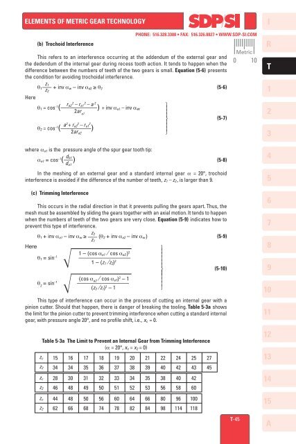
This type of interference can occur in the process of cutting an internal gear with a<br />
pinion cutter. Should that happen, there is danger of breaking the tooling. Table 5-3a shows<br />
the limit for the pinion cutter to prevent trimming interference when cutting a standard internal<br />
gear, with pressure angle 20°, and no profile shift, i.e., x c = 0.<br />
z c<br />
Table 5-3a The Limit to Prevent an Internal Gear from Trimming Interference<br />
(α = 20°, x c = x 2 = 0)<br />
z 2<br />
z c<br />
z 2<br />
z c<br />
z 2<br />
<strong>15</strong><br />
34<br />
28<br />
46<br />
44<br />
62<br />
16<br />
34<br />
30<br />
48<br />
48<br />
66<br />
17<br />
35<br />
31<br />
49<br />
50<br />
68<br />
18<br />
36<br />
32<br />
50<br />
56<br />
74<br />
19<br />
37<br />
33<br />
51<br />
60<br />
78<br />
20<br />
38<br />
34<br />
52<br />
64<br />
82<br />
21<br />
39<br />
35<br />
53<br />
66<br />
84<br />
22<br />
40<br />
38<br />
56<br />
80<br />
98<br />
24<br />
42<br />
40<br />
58<br />
96<br />
<strong>11</strong>4<br />
25<br />
43<br />
42<br />
60<br />
<strong>10</strong>0<br />
<strong>11</strong>8<br />
27<br />
45<br />
Metric<br />
0 <strong>10</strong><br />
T-45<br />
I<br />
R<br />
T<br />
1<br />
2<br />
3<br />
4<br />
5<br />
6<br />
7<br />
8<br />
9<br />
<strong>10</strong><br />
<strong>11</strong><br />
<strong>12</strong><br />
<strong>13</strong><br />
<strong>14</strong><br />
<strong>15</strong><br />
A