I R 1 2 3 4 5 6 7 8 9 10 11 12 13 T 14 15 A - SDP/SI
I R 1 2 3 4 5 6 7 8 9 10 11 12 13 T 14 15 A - SDP/SI
I R 1 2 3 4 5 6 7 8 9 10 11 12 13 T 14 15 A - SDP/SI

Create successful ePaper yourself
Turn your PDF publications into a flip-book with our unique Google optimized e-Paper software.
No.<br />
ELEMENTS OF METRIC GEAR TECHNOLOGY<br />
PHONE: 516.328.3300 • FAX: 516.326.8827 • WWW.<strong>SDP</strong>-<strong>SI</strong>.COM<br />
There are several theories concerning how to distribute the sum of coefficient of profile shift,<br />
(x 1 + x 2 ) into pinion, (x 1 ) and gear, (x 2 ) separately. BSS (British) and DIN (German) standards are<br />
the most often used. In the example above, the <strong>12</strong> tooth pinion was given sufficient correction<br />
to prevent undercut, and the residual profile shift was given to the mating gear.<br />
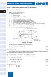
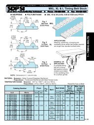
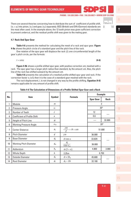
4.7 Rack And Spur Gear<br />
Table 4-6 presents the method for calculating the mesh of a rack and spur gear. Figure<br />
4-9a shows the pitch circle of a standard gear and the pitch line of the rack.<br />
One rotation of the spur gear will displace the rack (l) one circumferential length of the<br />
gear's pitch circle, per the formula:<br />
l = πmz (4-6)<br />
Figure 4-9b shows a profile shifted spur gear, with positive correction xm, meshed with a<br />
rack. The spur gear has a larger pitch radius than standard, by the amount xm. Also, the pitch<br />
line of the rack has shifted outward by the amount xm.<br />
Table 4-6 presents the calculation of a meshed profile shifted spur gear and rack. If the<br />
correction factor x 1 is 0, then it is the case of a standard gear meshed with the rack.<br />
The rack displacement, l, is not changed in any way by the profile shifting. Equation (4-6)<br />
remains applicable for any amount of profile shift.<br />
Table 4-6 The Calculation of Dimensions of a Profile Shifted Spur Gear and a Rack<br />
Item Symbol Formula<br />
1 Module m<br />
2 Pressure Angle α<br />
3 Number of Teeth z<br />
4 Coefficient of Profile Shift x<br />
5 Height of Pitch Line H<br />
6 Working Pressure Angle α w<br />
zm<br />
7 Center Distance a x –––– + H + xm<br />
2<br />
8 Pitch Diameter d zm<br />
9 Base Diameter d b d cos α<br />
<strong>14</strong> Root Diameter d f da – 2h<br />
d<br />
<strong>10</strong> Working Pitch Diameter d b<br />
w –––––<br />
cos α w<br />
<strong>11</strong> Addendum h a m (1 + x )<br />
<strong>12</strong> Whole Depth h 2.25m<br />
<strong>13</strong> Outside Diameter d a d + 2h a<br />
Spur Gear<br />
<strong>12</strong><br />
0.6<br />
Example<br />
3<br />
20°<br />
Rack<br />
––<br />
–– 32.000<br />
36.000<br />
33.829<br />
36.000<br />
20°<br />
51.800<br />
––<br />
4.800 3.000<br />
45.600<br />
32.<strong>10</strong>0<br />
6.750<br />
Metric<br />
0 <strong>10</strong><br />
––<br />
I<br />
R<br />
T<br />
1<br />
2<br />
3<br />
4<br />
5<br />
6<br />
7<br />
8<br />
9<br />
<strong>10</strong><br />
<strong>11</strong><br />
<strong>12</strong><br />
<strong>13</strong><br />
<strong>14</strong><br />
<strong>15</strong><br />
T-41<br />
A