I R 1 2 3 4 5 6 7 8 9 10 11 12 13 T 14 15 A - SDP/SI
I R 1 2 3 4 5 6 7 8 9 10 11 12 13 T 14 15 A - SDP/SI
I R 1 2 3 4 5 6 7 8 9 10 11 12 13 T 14 15 A - SDP/SI

Create successful ePaper yourself
Turn your PDF publications into a flip-book with our unique Google optimized e-Paper software.
ELEMENTS OF METRIC GEAR TECHNOLOGY<br />
4.4 Enlarged Pinions<br />
PHONE: 516.328.3300 • FAX: 516.326.8827 • WWW.<strong>SDP</strong>-<strong>SI</strong>.COM<br />
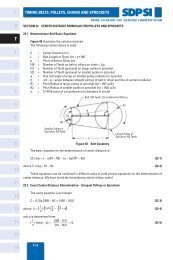
Undercutting of pinion teeth is undesirable because of losses of strength, contact ratio<br />
and smoothness of action. The severity of these faults depends upon how far below z c the teeth<br />
number is. Undercutting for the first few numbers is small and in many applications its adverse<br />
effects can be neglected.<br />
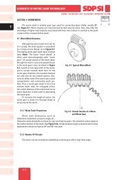
For very small numbers of teeth, such as ten and smaller, and for high-precision applications,<br />
undercutting should be avoided. This is achieved by pinion enlargement (or correction<br />
as often termed), where in the pinion teeth, still generated with a standard cutter, are shifted<br />
radially outward to form a full involute tooth free of undercut. The tooth is enlarged both radially<br />
and circumfe ren tially. Comparison of a tooth form before and after enlargement is shown in<br />
Figure 4-5.<br />
Metric<br />
0 <strong>10</strong><br />
I<br />
R<br />
T<br />
1<br />
2<br />
3<br />
Fig. 4-5 Comparison of Enlarged and Undercut<br />
Standard Pinion<br />
(<strong>13</strong> Teeth, 20° Pressure Angle, Fine Pitch Standard)<br />
Pitch Circle<br />
Base Circle<br />
4<br />
5<br />
6<br />
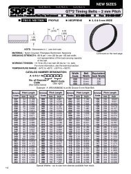
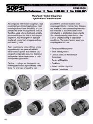
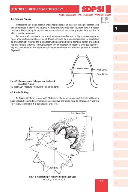
4.5 Profile Shifting<br />
As Figure 4-2 shows, a gear with 20 degrees of pressure angle and <strong>10</strong> teeth will have a<br />
huge undercut volume. To prevent undercut, a positive correction must be introduced. A positive<br />
correction, as in Figure 4-6, can prevent undercut.<br />
x m<br />
Rack Form Tool<br />
7<br />
8<br />
9<br />
<strong>10</strong><br />
d<br />
–– sin 2 α<br />
2<br />
d<br />
d b<br />
α<br />
O<br />
<strong>11</strong><br />
<strong>12</strong><br />
<strong>13</strong><br />
<strong>14</strong><br />
Fig. 4-6 Generating of Positive Shifted Spur Gear<br />
(α = 20°, z = <strong>10</strong>, x = +0.5)<br />
T-37<br />
<strong>15</strong><br />
A