I R 1 2 3 4 5 6 7 8 9 10 11 12 13 T 14 15 A - SDP/SI
I R 1 2 3 4 5 6 7 8 9 10 11 12 13 T 14 15 A - SDP/SI
I R 1 2 3 4 5 6 7 8 9 10 11 12 13 T 14 15 A - SDP/SI

Create successful ePaper yourself
Turn your PDF publications into a flip-book with our unique Google optimized e-Paper software.
I<br />
R<br />
T<br />
1<br />
2<br />
3<br />
4<br />
5<br />
6<br />
7<br />
8<br />
ELEMENTS OF METRIC GEAR TECHNOLOGY<br />
PHONE: 516.328.3300 • FAX: 516.326.8827 • WWW.<strong>SDP</strong>-<strong>SI</strong>.COM<br />
Elements of Metric Gear Technology<br />
The Technical Section of this catalog is the result of close cooperation of Stock<br />
Drive Products / Sterling Instrument (<strong>SDP</strong>/<strong>SI</strong>) staff with experts in the fields of gear<br />
design and manufacturing. We wish, therefore, to recognize the contribution of the<br />
following company and individuals:<br />
KHK - Kohara Gear Company of Japan, that provided the material<br />
previously published in this catalog.<br />
Dr. George Michalec, former Professor of Mechanical Engineering at<br />
Stevens Institute of Technology, and author of a large number of<br />
publications related to precision gearing.<br />
Staff of <strong>SDP</strong>/<strong>SI</strong>:<br />
Dr. Frank Buchsbaum, Executive Vice President, Designatronics, Inc.<br />
Dr. Hitoshi Tanaka, Senior Vice President, Designatronics, Inc.<br />
Linda Shuett, Manager, Graphic Communications<br />
John Chiaramonte, Senior Graphic Artist<br />
Szymon Sondej, Graphic Artist<br />
Melanie Hasranah, Graphic Artist<br />
Luis C. Quinteros, Product Engineer<br />
Milton Epstein, Assistant Editor<br />
...and many others on the staff who individually and collectively spent their time and<br />
effort that resulted in the publication of this text.<br />
No part of this publication may be reproduced in any form or by any means without<br />
prior written permission of the company. This does not cover material which was<br />
attributed to another publication.<br />
Metric<br />
0 <strong>10</strong><br />
9<br />
<strong>10</strong><br />
<strong>11</strong><br />
<strong>12</strong><br />
<strong>13</strong><br />
<strong>14</strong><br />
<strong>15</strong><br />
A<br />
T-0
ELEMENTS OF METRIC GEAR TECHNOLOGY<br />
I<br />
TABLE OF CONTENTS<br />
PHONE: 516.328.3300 • FAX: 516.326.8827 • WWW.<strong>SDP</strong>-<strong>SI</strong>.COM<br />
PAGE<br />
R<br />
SECTION 1 INTRODUCTION TO METRIC GEARS ..........................................................................T-7<br />
1.1 Comparison Of Metric Gears With American Inch Gears........................................T-8<br />
1.1.1 Comparison of Basic Racks.......................................................................T-8<br />
1.1.2 Metric ISO Basic Rack................................................................................T-8<br />
1.1.3 Comparison of Gear Calculation Equations.............................................T-9<br />
1.2 Metric Standards Worldwide........................................................................................T-9<br />
1.2.1 ISO Standards...............................................................................................T-9<br />
1.2.2 Foreign Metric Standards...........................................................................T-9<br />
1.3 Japanese Metric Standards In This Text....................................................................T-9<br />
1.3.1 Application of JIS Standards.....................................................................T-9<br />
1.3.2 Symbols.........................................................................................................T-<strong>13</strong><br />
1.3.3 Terminology...................................................................................................T-16<br />
1.3.4 Conversion....................................................................................................T-16<br />
SECTION 2 INTRODUCTION TO GEAR TECHNOLOGY ..................................................................T-17<br />
2.1 Basic Geometry Of Spur Gears.....................................................................................T-17<br />
2.2 The Law Of Gearing........................................................................................................T-19<br />
2.3 The Involute Curve..........................................................................................................T-19<br />
2.4 Pitch Circles.....................................................................................................................T-20<br />
2.5 Pitch And Module...........................................................................................................T-20<br />
2.6 Module Sizes And Standards........................................................................................T-21<br />
2.7 Gear Types And Axial Arrangements..........................................................................T-26<br />
2.7.1 Parallel Axes Gears.....................................................................................T-26<br />
2.7.2 Intersecting Axes Gears.............................................................................T-28<br />
2.7.3 Nonparallel and Nonintersecting Axes Gears........................................T-28<br />
2.7.4 Other Special Gears....................................................................................T-29<br />
SECTION 3 DETAILS OF INVOLUTE GEARING ...............................................................................T-30<br />
3.1 Pressure Angle................................................................................................................T-30<br />
3.2 Proper Meshing And Contact Ratio.............................................................................T-30<br />
3.2.1 Contact Ratio................................................................................................T-32<br />
3.3 The Involute Function.....................................................................................................T-32<br />
SECTION 4 SPUR GEAR CALCULATIONS .......................................................................................T-34<br />
4.1 Standard Spur Gear........................................................................................................T-34<br />
4.2 The Generating Of A Spur Gear....................................................................................T-35<br />
4.3 Undercutting....................................................................................................................T-36<br />
4.4 Enlarged Pinions.............................................................................................................T-37<br />
4.5 Profile Shifting.................................................................................................................T-37<br />
4.6 Profile Shifted Spur Gear...............................................................................................T-39<br />
4.7 Rack And Spur Gear.......................................................................................................T-41<br />
T<br />
1<br />
2<br />
3<br />
4<br />
5<br />
6<br />
7<br />
8<br />
9<br />
<strong>10</strong><br />
<strong>11</strong><br />
<strong>12</strong><br />
<strong>13</strong><br />
<strong>14</strong><br />
<strong>15</strong><br />
T-1<br />
A
I<br />
ELEMENTS OF METRIC GEAR TECHNOLOGY<br />
R<br />
TABLE OF CONTENTS<br />
PHONE: 516.328.3300 • FAX: 516.326.8827 • WWW.<strong>SDP</strong>-<strong>SI</strong>.COM<br />
PAGE<br />
T<br />
1<br />
2<br />
3<br />
4<br />
5<br />
6<br />
7<br />
8<br />
9<br />
<strong>10</strong><br />
<strong>11</strong><br />
<strong>12</strong><br />
<strong>13</strong><br />
SECTION 5 INTERNAL GEARS ..........................................................................................................T-42<br />
5.1 Internal Gear Calculations.............................................................................................T-42<br />
5.2 Interference In Internal Gears......................................................................................T-44<br />
5.3 Internal Gear With Small Differences In Numbers Of Teeth...................................T-46<br />
SECTION 6 HELICAL GEARS .............................................................................................................T-47<br />
6.1 Generation Of The Helical Tooth...................................................................................T-48<br />
6.2 Fundamentals Of Helical Teeth.....................................................................................T-48<br />
6.3 Equivalent Spur Gear......................................................................................................T-50<br />
6.4 Helical Gear Pressure Angle.........................................................................................T-51<br />
6.5 Importance Of Normal Plane Geometry......................................................................T-51<br />
6.6 Helical Tooth Proportions..............................................................................................T-51<br />
6.7 Parallel Shaft Helical Gear Meshes.............................................................................T-51<br />
6.8 Helical Gear Contact Ratio............................................................................................T-52<br />
6.9 Design Considerations...................................................................................................T-52<br />
6.9.1 Involute Interference...................................................................................T-52<br />
6.9.2 Normal vs. Radial Module (Pitch)..............................................................T-52<br />
6.<strong>10</strong> Helical Gear Calculations..............................................................................................T-53<br />
6.<strong>10</strong>.1 Normal System Helical Gear......................................................................T-53<br />
6.<strong>10</strong>.2 Radial System Helical Gear........................................................................T-54<br />
6.<strong>10</strong>.3 Sunderland Double Helical Gear...............................................................T-55<br />
6.<strong>10</strong>.4 Helical Rack..................................................................................................T-56<br />
SECTION 7 SCREW GEAR OR CROSSED HELICAL GEAR MESHES ............................................T-57<br />
7.1 Features .........................................................................................................................T-57<br />
7.1.1 Helix Angle and Hands................................................................................T-57<br />
7.1.2 Module...........................................................................................................T-57<br />
7.1.3 Center Distance............................................................................................T-58<br />
7.1.4 Velocity Ratio................................................................................................T-58<br />
7.2 Screw Gear Calculations...............................................................................................T-58<br />
7.3 Axial Thrust Of Helical Gears........................................................................................T-60<br />
SECTION 8 BEVEL GEARING .............................................................................................................T-60<br />
8.1 Development And Geometry Of Bevel Gears.............................................................T-61<br />
8.2 Bevel Gear Tooth Proportions.......................................................................................T-62<br />
8.3 Velocity Ratio...................................................................................................................T-62<br />
8.4 Forms Of Bevel Teeth......................................................................................................T-62<br />
8.5 Bevel Gear Calculations................................................................................................T-64<br />
8.5.1 Gleason Straight Bevel Gears....................................................................T-66<br />
8.5.2 Standard Straight Bevel Gears..................................................................T-68<br />
8.5.3 Gleason Spiral Bevel Gears.......................................................................T-69<br />
8.5.4 Gleason Zerol Spiral Bevel Gears.............................................................T-70<br />
<strong>14</strong><br />
<strong>15</strong><br />
A<br />
T-2
ELEMENTS OF METRIC GEAR TECHNOLOGY<br />
I<br />
TABLE OF CONTENTS<br />
PHONE: 516.328.3300 • FAX: 516.326.8827 • WWW.<strong>SDP</strong>-<strong>SI</strong>.COM<br />
PAGE<br />
R<br />
SECTION 9 WORM MESH .................................................................................................................T-72<br />
9.1 Worm Mesh Geometry...................................................................................................T-72<br />
9.1.1 Worm Tooth Proportions.............................................................................T-72<br />
9.1.2 Number of Threads......................................................................................T-72<br />
9.1.3 Pitch Diameters, Lead and Lead Angle....................................................T-73<br />
9.1.4 Center Distance............................................................................................T-73<br />
9.2 Cylindrical Worm Gear Calculations............................................................................T-73<br />
9.2.1 Axial Module Worm Gears.........................................................................T-75<br />
9.2.2 Normal Module System Worm Gears.......................................................T-76<br />
9.3 Crowning Of The Worm Gear Tooth.............................................................................T-77<br />
9.4 Self-Locking Of Worm Mesh.........................................................................................T-80<br />
SECTION <strong>10</strong> TOOTH THICKNESS .....................................................................................................T-81<br />
<strong>10</strong>.1 Chordal Thickness Measurement................................................................................T-81<br />
<strong>10</strong>.1.1 Spur Gears....................................................................................................T-81<br />
<strong>10</strong>.1.2 Spur Racks and Helical Racks...................................................................T-81<br />
<strong>10</strong>.1.3 Helical Gears................................................................................................T-82<br />
<strong>10</strong>.1.4 Bevel Gears...................................................................................................T-82<br />
<strong>10</strong>.1.5 Worms and Worm Gears............................................................................T-84<br />
<strong>10</strong>.2 Span Measurement Of Teeth........................................................................................T-86<br />
<strong>10</strong>.2.1 Spur and Internal Gears..............................................................................T-86<br />
<strong>10</strong>.2.2 Helical Gears................................................................................................T-87<br />
<strong>10</strong>.3 Over Pins (Balls) Measurement....................................................................................T-88<br />
<strong>10</strong>.3.1 Spur Gears....................................................................................................T-89<br />
<strong>10</strong>.3.2 Spur Racks and Helical Racks...................................................................T-91<br />
<strong>10</strong>.3.3 Internal Gears...............................................................................................T-92<br />
<strong>10</strong>.3.4 Helical Gears................................................................................................T-94<br />
<strong>10</strong>.3.5 Three Wire Method of Worm Measurement...........................................T-96<br />
<strong>10</strong>.4 Over Pins Measurements For Fine Pitch Gears With<br />
Specific Numbers Of Teeth............................................................................................T-98<br />
SECTION <strong>11</strong> CONTACT RATIO ...........................................................................................................T-<strong>10</strong>8<br />
<strong>11</strong>.1 Radial Contact Ratio Of Spur And Helical Gears, e a ...............................................T-<strong>10</strong>8<br />
<strong>11</strong>.2 Contact Ratio Of Bevel Gears, e a ................................................................................T-<strong>10</strong>9<br />
<strong>11</strong>.3 Contact Ratio For Nonparallel And Nonintersecting Axes Pairs, e .......................T-1<strong>10</strong><br />
<strong>11</strong>.4 Axial (Overlap) Contact Ratio, e b ................................................................................T-1<strong>10</strong><br />
SECTION <strong>12</strong> GEAR TOOTH MODIFICATIONS .................................................................................T-<strong>11</strong>1<br />
<strong>12</strong>.1 Tooth Tip Relief................................................................................................................T-<strong>11</strong>1<br />
<strong>12</strong>.2 Crowning And Side Relieving........................................................................................T-<strong>11</strong>2<br />
<strong>12</strong>.3 Topping And Semitopping .............................................................................................T-<strong>11</strong>2<br />
T<br />
1<br />
2<br />
3<br />
4<br />
5<br />
6<br />
7<br />
8<br />
9<br />
<strong>10</strong><br />
<strong>11</strong><br />
<strong>12</strong><br />
<strong>13</strong><br />
<strong>14</strong><br />
<strong>15</strong><br />
T-3<br />
A
I<br />
R<br />
T<br />
1<br />
2<br />
3<br />
4<br />
5<br />
6<br />
7<br />
8<br />
9<br />
<strong>10</strong><br />
<strong>11</strong><br />
<strong>12</strong><br />
<strong>13</strong><br />
<strong>14</strong><br />
ELEMENTS OF METRIC GEAR TECHNOLOGY<br />
TABLE OF CONTENTS<br />
PHONE: 516.328.3300 • FAX: 516.326.8827 • WWW.<strong>SDP</strong>-<strong>SI</strong>.COM<br />
PAGE<br />
SECTION <strong>13</strong> GEAR TRAINS ...............................................................................................................T-<strong>11</strong>3<br />
<strong>13</strong>.1 Single-Stage Gear Train.................................................................................................T-<strong>11</strong>3<br />
<strong>13</strong>.1.1 Types of Single-Stage Gear Trains............................................................T-<strong>11</strong>3<br />
<strong>13</strong>.2 Two-Stage Gear Train.....................................................................................................T-<strong>11</strong>4<br />
<strong>13</strong>.3 Planetary Gear System..................................................................................................T-<strong>11</strong>5<br />
<strong>13</strong>.3.1 Relationship Among the Gears in a Planetary Gear System................T-<strong>11</strong>6<br />
<strong>13</strong>.3.2 Speed Ratio of Planetary Gear System....................................................T-<strong>11</strong>7<br />
<strong>13</strong>.4 Constrained Gear System..............................................................................................T-<strong>11</strong>8<br />
SECTION <strong>14</strong> BACKLASH ....................................................................................................................T-<strong>11</strong>9<br />
<strong>14</strong>.1 Definition Of Backlash....................................................................................................T-<strong>12</strong>0<br />
<strong>14</strong>.2 Backlash Relationships..................................................................................................T-<strong>12</strong>3<br />
<strong>14</strong>.2.1 Backlash of a Spur Gear Mesh..................................................................T-<strong>12</strong>3<br />
<strong>14</strong>.2.2 Backlash of Helical Gear Mesh.................................................................T-<strong>12</strong>4<br />
<strong>14</strong>.2.3 Backlash of Straight Bevel Gear Mesh....................................................T-<strong>12</strong>5<br />
<strong>14</strong>.2.4 Backlash of a Spiral Bevel Gear Mesh....................................................T-<strong>12</strong>5<br />
<strong>14</strong>.2.5 Backlash of Worm Gear Mesh...................................................................T-<strong>12</strong>6<br />
<strong>14</strong>.3 Tooth Thickness And Backlash.....................................................................................T-<strong>12</strong>6<br />
<strong>14</strong>.4 Gear Train And Backlash...............................................................................................T-<strong>12</strong>7<br />
<strong>14</strong>.5 Methods Of Controlling Backlash................................................................................T-<strong>12</strong>8<br />
<strong>14</strong>.5.1 Static Method...............................................................................................T-<strong>12</strong>8<br />
<strong>14</strong>.5.2 Dynamic Methods........................................................................................T-<strong>12</strong>9<br />
SECTION <strong>15</strong> GEAR ACCURACY .........................................................................................................T-<strong>13</strong>1<br />
<strong>15</strong>.1 Accuracy Of Spur And Helical Gears..........................................................................T-<strong>13</strong>1<br />
<strong>15</strong>.1.1 Pitch Errors of Gear Teeth..........................................................................T-<strong>13</strong>1<br />
<strong>15</strong>.1.2 Tooth Profile Error, f f ...................................................................................T-<strong>13</strong>3<br />
<strong>15</strong>.1.3 Runout Error of Gear Teeth, F r ...................................................................T-<strong>13</strong>3<br />
<strong>15</strong>.1.4 Lead Error, f b ................................................................................................T-<strong>13</strong>3<br />
<strong>15</strong>.1.5 Outside Diameter Runout and Lateral Runout.........................................T-<strong>13</strong>5<br />
<strong>15</strong>.2 Accuracy Of Bevel Gears..............................................................................................T-<strong>13</strong>5<br />
<strong>15</strong>.3 Running (Dynamic) Gear Testing..................................................................................T-<strong>13</strong>7<br />
SECTION 16 GEAR FORCES ...............................................................................................................T-<strong>13</strong>8<br />
16.1 Forces In A Spur Gear Mesh.........................................................................................T-<strong>13</strong>9<br />
16.2 Forces In A Helical Gear Mesh.....................................................................................T-<strong>13</strong>9<br />
16.3 Forces In A Straight Bevel Gear Mesh........................................................................T-<strong>14</strong>0<br />
16.4 Forces In A Spiral Bevel Gear Mesh...........................................................................T-<strong>14</strong>2<br />
16.4.1 Tooth Forces on a Convex Side Profile.....................................................T-<strong>14</strong>2<br />
16.4.2 Tooth Forces on a Concave Side Profile..................................................T-<strong>14</strong>3<br />
16.5 Forces In A Worm Gear Mesh......................................................................................T-<strong>14</strong>6<br />
16.5.1 Worm as the Driver......................................................................................T-<strong>14</strong>6<br />
16.5.2 Worm Gear as the Driver............................................................................T-<strong>14</strong>8<br />
16.6 Forces In A Screw Gear Mesh.....................................................................................T-<strong>14</strong>8<br />
<strong>15</strong><br />
A<br />
T-4
ELEMENTS OF METRIC GEAR TECHNOLOGY<br />
TABLE OF CONTENTS<br />
PHONE: 516.328.3300 • FAX: 516.326.8827 • WWW.<strong>SDP</strong>-<strong>SI</strong>.COM<br />
PAGE<br />
SECTION 17 STRENGTH AND DURABILITY OF GEARS ................................................................ T-<strong>15</strong>0<br />
17.1 Bending Strength Of Spur And Helical Gears............................................................ T-<strong>15</strong>0<br />
17.1.1 Determination of Factors in the Bending Strength Equation................ T-<strong>15</strong>1<br />
17.1.2 Tooth Profile Factor, Y F ............................................................................... T-<strong>15</strong>1<br />
17.1 3 Load Distribution Factor, Y e ....................................................................... T-<strong>15</strong>1<br />
17.1 4 Helix Angle Factor, Y b ................................................................................. T-<strong>15</strong>3<br />
17.1.5 Life Factor, K L ............................................................................................... T-<strong>15</strong>4<br />
17.1.6 Dimension Factor of Root Stress, K FX ....................................................... T-<strong>15</strong>4<br />
17.1.7 Dynamic Load Factor, K V ............................................................................ T-<strong>15</strong>4<br />
17.1.8 Overload Factor, K O ..................................................................................... T-<strong>15</strong>5<br />
17.1.9 Safety Factor of Bending Failure, S F ........................................................ T-<strong>15</strong>5<br />
17.1.<strong>10</strong> Allowable Bending Stress at Root, s F lim ................................................. T-<strong>15</strong>5<br />
17.1.<strong>11</strong> Example of Bending Strength Calculation............................................... T-<strong>15</strong>9<br />
17.2 Surface Strength Of Spur And Helical Gears............................................................. T-160<br />
17.2.1 Conversion Formulas................................................................................... T-160<br />
17.2.2 Surface Strength Equations....................................................................... T-160<br />
17.2.3 Determination of Factors in the Surface Strength Equations............... T-160<br />
17.2.4 Contact Ratio Factor, Z e ............................................................................. T-162<br />
17.2.5 Helix Angle Factor, Z b ................................................................................ T-163<br />
17.2.6 Life Factor, K HL .............................................................................................. T-163<br />
17.2.7 Lubricant Factor, Z L ..................................................................................... T-163<br />
17.2.8 Surface Roughness Factor, Z R .................................................................. T-163<br />
17.2.9 Sliding Speed Factor, Z V ............................................................................. T-164<br />
17.2.<strong>10</strong> Hardness Ratio Factor, Z W ......................................................................... T-164<br />
17.2.<strong>11</strong> Dimension Factor, K HX ................................................................................. T-164<br />
17.2.<strong>12</strong> Tooth Flank Load Distribution Factor, K Hb ............................................... T-164<br />
17.2.<strong>13</strong> Dynamic Load Factor, K V ............................................................................ T-165<br />
17.2.<strong>14</strong> Overload Factor, K O ..................................................................................... T-165<br />
17.2.<strong>15</strong> Safety Factor for Pitting, S H ....................................................................... T-165<br />
17.2.16 Allowable Hertz Stress, s H lim .................................................................... T-165<br />
17.2.17 Example of Surface Stress Calculation.................................................... T-170<br />
17.3 Bending Strength Of Bevel Gears................................................................................ T-171<br />
17.3.1 Conversion Formulas................................................................................... T-171<br />
17.3.2 Bending Strength Equations...................................................................... T-172<br />
17.3.3 Determination of Factors in Bending Strength Equations..................... T-172<br />
17.3.4 Examples of Bevel Gear Bending Strength Calculations...................... T-179<br />
17.4 Surface Strength Of Bevel Gears................................................................................. T-180<br />
17.4.1 Basic Conversion Formulas........................................................................ T-180<br />
17.4.2 Surface Strength Equations....................................................................... T-180<br />
17.4.3 Determination of Factors in Surface Strength Equations..................... T-181<br />
17.4.4 Examples of Bevel Gear Surface Strength Calculations....................... T-184<br />
17.5 Strength Of Worm Gearing............................................................................................ T-185<br />
17.5.1 Basic Formulas............................................................................................. T-185<br />
17.5.2 Torque, Tangential Force and Efficiency.................................................. T-186<br />
17.5.3 Friction Coefficient, m ................................................................................. T-186<br />
17.5.4 Surface Strength of Worm Gearing Mesh............................................... T-187<br />
17.5.5 Determination of Factors in Worm Gear Surface Strength EquationsT-188<br />
17.5.6 Examples of Worm Mesh Strength Calculation...................................... T-193<br />
I<br />
R<br />
T<br />
1<br />
2<br />
3<br />
4<br />
5<br />
6<br />
7<br />
8<br />
9<br />
<strong>10</strong><br />
<strong>11</strong><br />
<strong>12</strong><br />
<strong>13</strong><br />
<strong>14</strong><br />
<strong>15</strong><br />
T-5<br />
A
I<br />
ELEMENTS OF METRIC GEAR TECHNOLOGY<br />
R<br />
TABLE OF CONTENTS<br />
PHONE: 516.328.3300 • FAX: 516.326.8827 • WWW.<strong>SDP</strong>-<strong>SI</strong>.COM<br />
PAGE<br />
T<br />
1<br />
2<br />
3<br />
4<br />
5<br />
6<br />
7<br />
8<br />
9<br />
<strong>10</strong><br />
<strong>11</strong><br />
<strong>12</strong><br />
<strong>13</strong><br />
<strong>14</strong><br />
SECTION 18 DE<strong>SI</strong>GN OF PLASTIC GEARS ......................................................................................T-194<br />
18.1 General Considerations Of Plastic Gearing................................................................T-194<br />
18.2 Properties Of Plastic Gear Materials...........................................................................T-194<br />
18.3 Choice Of Pressure Angles And Modules..................................................................T-204<br />
18.4 Strength Of Plastic Spur Gears.....................................................................................T-204<br />
18.4.1 Bending Strength of Spur Gears...............................................................T-205<br />
18.4.2 Surface Strength of Plastic Spur Gears...................................................T-206<br />
18.4.3 Bending Strength of Plastic Bevel Gears................................................T-206<br />
18.4.4 Bending Strength of Plastic Worm Gears................................................T-209<br />
18.4.5 Strength of Plastic Keyway........................................................................T-2<strong>10</strong><br />
18.5 Effect Of Part Shrinkage On Plastic Gear Design......................................................T-2<strong>10</strong><br />
18.6 Proper Use Of Plastic Gears.........................................................................................T-2<strong>12</strong><br />
18.6.1 Backlash........................................................................................................T-2<strong>12</strong><br />
18.6.2 Environment and Tolerances......................................................................T-2<strong>13</strong><br />
18.6.3 Avoiding Stress Concentration..................................................................T-2<strong>13</strong><br />
18.6.4 Metal Inserts.................................................................................................T-2<strong>13</strong><br />
18.6.5 Attachment of Plastic Gears to Shafts.....................................................T-2<strong>14</strong><br />
18.6.6 Lubrication....................................................................................................T-2<strong>14</strong><br />
18.6.7 Molded vs. Cut Plastic Gears.....................................................................T-2<strong>15</strong><br />
18.6.8 Elimination of Gear Noise...........................................................................T-2<strong>15</strong><br />
18.7 Mold Construction..........................................................................................................T-216<br />
SECTION 19 FEATURES OF TOOTH SURFACE CONTACT .............................................................T-221<br />
19.1 Surface Contact Of Spur And Helical Meshes...........................................................T-221<br />
19.2 Surface Contact Of A Bevel Gear.................................................................................T-221<br />
19.2.1 The Offset Error of Shaft Alignment..........................................................T-222<br />
19.2.2 The Shaft Angle Error of Gear Box............................................................T-222<br />
19.2.3 Mounting Distance Error............................................................................T-222<br />
19.3 Surface Contact Of Worm And Worm Gear................................................................T-223<br />
19.3.1 Shaft Angle Error..........................................................................................T-223<br />
19.3.2 Center Distance Error..................................................................................T-224<br />
19.3.3 Mounting Distance Error............................................................................T-224<br />
SECTION 20 LUBRICATION OF GEARS ............................................................................................T-225<br />
20.1 Methods Of Lubrication.................................................................................................T-225<br />
20.1.1 Grease Lubrication......................................................................................T-225<br />
20.1.2 Splash Lubrication.......................................................................................T-226<br />
20.1.3 Forced-Circulation Lubrication..................................................................T-227<br />
20.2 Gear Lubricants...............................................................................................................T-227<br />
20.2.1 Viscosity of Lubricant..................................................................................T-227<br />
20.2.2 Selection of Lubricant.................................................................................T-229<br />
SECTION 21 GEAR NOISE ..................................................................................................................T-231<br />
REFERENCES AND LITERATURE OF GENERAL INTEREST .............................................................T-232<br />
<strong>15</strong><br />
A<br />
T-6
ELEMENTS OF METRIC GEAR TECHNOLOGY<br />
PHONE: 516.328.3300 • FAX: 516.326.8827 • WWW.<strong>SDP</strong>-<strong>SI</strong>.COM<br />
Gears are some of the most important elements used in machinery. There are few<br />
mechanical devices that do not have the need to transmit power and motion between<br />
rotating shafts. Gears not only do this most satisfactorily, but can do so with uniform motion<br />
and reliability. In addition, they span the entire range of applications from large to small. To<br />
summarize:<br />
1. Gears offer positive transmission of power.<br />
2. Gears range in size from small miniature instrument installations, that<br />
measure in only several millimeters in diameter, to huge powerful gears in<br />
turbine drives that are several meters in diameter.<br />
3. Gears can provide position transmission with very high angular or linear<br />
accuracy; such as used in servomechanisms and military equipment.<br />
4. Gears can couple power and motion between shafts whose axes are<br />
parallel, intersecting or skew.<br />
5. Gear designs are standardized in accordance with size and shape which<br />
provides for widespread interchangeability.<br />
This technical manual is written as an aid for the designer who is a beginner or only<br />
superficially knowledgeable about gearing. It provides fundamental theoretical and practical<br />
information. Admittedly, it is not intended for experts.<br />
Those who wish to obtain further information and special details should refer to the<br />
reference list at the end of this text and other literature on mechanical machinery and<br />
components.<br />
SECTION 1<br />
INTRODUCTION TO METRIC GEARS<br />
This technical section is dedicated to details of metric gearing because of its<br />
increasing importance. Currently, much gearing in the United States is still based upon the<br />
inch system. However, with most of the world metricated, the use of metric gearing in the<br />
United States is definitely on the increase, and inevitably at some future date it will be the<br />
exclusive system.<br />
It should be appreciated that in the United States there is a growing amount of metric<br />
gearing due to increasing machinery and other equipment imports. This is particularly true<br />
of manufacturing equipment, such as printing presses, paper machines and machine tools.<br />
Automobiles are another major example, and one that impacts tens of millions of individuals.<br />
Further spread of metric gearing is inevitable since the world that surrounds the United<br />
States is rapidly approaching complete conformance. England and Canada, once bastions<br />
of the inch system, are well down the road of metrication, leaving the United States as the<br />
only significant exception.<br />
Thus, it becomes prudent for engineers and designers to not only become familiar with<br />
metric gears, but also to incorporate them in their designs. Certainly, for export products it<br />
is imperative; and for domestic products it is a serious consideration. The U.S. Government,<br />
and in particular the military, is increasingly insisting upon metric based equipment<br />
designs.<br />
Recognizing that most engineers and designers have been reared in an environment of<br />
heavy use of the inch system and that the amount of literature about metric gears is limited,<br />
we are offering this technical gear section as an aid to understanding and use of metric<br />
gears. In the following pages, metric gear standards are introduced along with information<br />
about interchangeability and noninterchangeability. Although gear theory is the same for<br />
both the inch and metric systems, the formulae for metric gearing take on a different set of<br />
symbols. These equations are fully defined in the metric system. The coverage is thorough<br />
and complete with the intention that this be a source for all information about gearing with<br />
definition in a metric format.<br />
Metric<br />
0 <strong>10</strong><br />
T-7<br />
I<br />
R<br />
T<br />
1<br />
2<br />
3<br />
4<br />
5<br />
6<br />
7<br />
8<br />
9<br />
<strong>10</strong><br />
<strong>11</strong><br />
<strong>12</strong><br />
<strong>13</strong><br />
<strong>14</strong><br />
<strong>15</strong><br />
A
I<br />
R<br />
T<br />
1<br />
2<br />
3<br />
4<br />
5<br />
6<br />
7<br />
8<br />
9<br />
<strong>10</strong><br />
<strong>11</strong><br />
<strong>12</strong><br />
ELEMENTS OF METRIC GEAR TECHNOLOGY<br />
1.1 Comparison Of Metric Gears With American Inch Gears<br />
1.1.1 Comparison of Basic Racks<br />
PHONE: 516.328.3300 • FAX: 516.326.8827 • WWW.<strong>SDP</strong>-<strong>SI</strong>.COM<br />
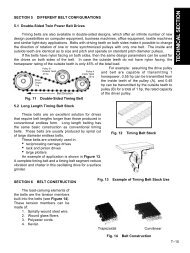
In all modern gear systems, the rack is the basis for tooth design and manufacturing<br />
tooling. Thus, the similarities and differences between the two systems can be put into proper<br />
perspective with comparison of the metric and inch basic racks.<br />
In both systems, the basic rack is normalized for a unit size. For the metric rack it is 1<br />
module, and for the inch rack it is 1 diametral pitch.<br />
1.1.2 Metric ISO Basic Rack<br />
The standard ISO metric rack is detailed in Figure 1-1. It is now the accepted standard<br />
for the international community, it having eliminated a number of minor differences that existed<br />
between the earlier versions of Japanese, German and Russian modules. For comparison, the<br />
standard inch rack is detailed in Figure 1-2. Note that there are many similarities. The principal<br />
factors are the same for both racks. Both are normalized for unity; that is, the metric rack is<br />
specified in terms of 1 module, and the inch rack in terms of 1 diametral pitch.<br />
Pitch Line<br />
Fig. 1-2<br />
2.25<br />
1<br />
1.25<br />
20°<br />
p<br />
p p<br />
–– ––2 2<br />
0.02 max.<br />
Pitch Line<br />
0.6 max.<br />
r f = 0.38<br />
Fig. 1-1 The Basic Metric Rack From ISO 53 Normalized For Module 1<br />
s<br />
p<br />
r f<br />
a<br />
The Basic Inch Diametral Pitch Rack Normalized For 1 Diametral Pitch<br />
h a<br />
h f<br />
c<br />
h w<br />
h<br />
Metric<br />
0 <strong>10</strong><br />
h a = Addendum<br />
h f = Dedendum<br />
c = Clearance<br />
h w = Working Depth<br />
h = Whole Depth<br />
p = Circular Pitch<br />
r f = Root Radius<br />
s = Circular Tooth Thickness<br />
a = Pressure Angle<br />
<strong>13</strong><br />
<strong>14</strong><br />
<strong>15</strong><br />
A<br />
T-8
ELEMENTS OF METRIC GEAR TECHNOLOGY<br />
PHONE: 516.328.3300 • FAX: 516.326.8827 • WWW.<strong>SDP</strong>-<strong>SI</strong>.COM<br />
From the normalized metric rack, corresponding dimensions for any module are obtained<br />
by multiplying each rack dimension by the value of the specific module m. The major tooth<br />
parameters are defined by the standard, as:<br />
Tooth Form:<br />
Pressure Angle:<br />
Addendum:<br />
Dedendum:<br />
Root Radius:<br />
Tip Radius:<br />
Straight-sided full depth, forming the basis of a family of<br />
full depth interchangeable gears.<br />
A 20° pressure angle, which conforms to worldwide<br />
acceptance of this as the most versatile pressure angle.<br />
This is equal to the module m, which is similar to the inch<br />
value that becomes 1/p.<br />
This is 1.25 m ; again similar to the inch rack value.<br />
The metric rack value is slightly greater than the American<br />
inch rack value.<br />
A maximum value is specified. This is a deviation from the<br />
American inch rack which does not specify a rounding.<br />
1.1.3 Comparison of Gear Calculation Equations<br />
Most gear equations that are used for diametral pitch inch gears are equally applicable to<br />
metric gears if the module m is substituted for diametral pitch. However, there are exceptions<br />
when it is necessary to use dedicated metric equations. Thus, to avoid confusion and errors, it<br />
is most effective to work entirely with and within the metric system.<br />
1.2 Metric Standards Worldwide<br />
1.2.1 ISO Standards<br />
Metric standards have been coordinated and standardized by the International Standards<br />
Organization (ISO). A listing of the most pertinent standards is given in Table 1-1.<br />
1.2.2 Foreign Metric Standards<br />
Most major industrialized countries have been using metric gears for a long time and<br />
consequently had developed their own standards prior to the establishment of ISO and <strong>SI</strong><br />
units. In general, they are very similar to the ISO standards. The key foreign metric standards<br />
are listed in Table 1-2 for reference.<br />
1.3 Japanese Metric Standards In This Text<br />
1.3.1 Application of JIS Standards<br />
Japanese Industrial Standards (JIS) define numerous engineering subjects including<br />
gearing. The originals are generated in Japanese, but they are translated and published in<br />
English by the Japanese Standards Association.<br />
Considering that many metric gears are produced in Japan, the JIS standards may apply.<br />
These essentially conform to all aspects of the ISO standards.<br />
Metric<br />
0 <strong>10</strong><br />
I<br />
R<br />
T<br />
1<br />
2<br />
3<br />
4<br />
5<br />
6<br />
7<br />
8<br />
9<br />
<strong>10</strong><br />
<strong>11</strong><br />
<strong>12</strong><br />
<strong>13</strong><br />
<strong>14</strong><br />
<strong>15</strong><br />
T-9<br />
A
I<br />
ELEMENTS OF METRIC GEAR TECHNOLOGY<br />
R<br />
T<br />
1<br />
2<br />
3<br />
4<br />
5<br />
6<br />
7<br />
8<br />
9<br />
<strong>10</strong><br />
<strong>11</strong><br />
<strong>12</strong><br />
<strong>13</strong><br />
<strong>14</strong><br />
<strong>15</strong><br />
A<br />
ISO 53:1974<br />
ISO 54:1977<br />
ISO 677:1976<br />
ISO 678:1976<br />
ISO 701:1976<br />
ISO <strong>11</strong>22-1:1983<br />
ISO <strong>13</strong>28:1975<br />
ISO <strong>13</strong>40:1976<br />
ISO <strong>13</strong>41:1976<br />
ISO 2203:1973<br />
ISO 2490:1975<br />
ISO/TR 4467:1982<br />
ISO 4468:1982<br />
ISO 8579-1:1993<br />
ISO 8579-2:1993<br />
ISO/TR <strong>10</strong>064-1:1992<br />
AS B 62 1965<br />
AS B 66 1969<br />
AS B 2<strong>14</strong> 1966<br />
AS B 217 1966<br />
AS 1637<br />
NF E 23-001 1972<br />
NF E 23-002 1972<br />
NF E 23-005 1965<br />
NF E 23-006 1967<br />
NF E 23-0<strong>11</strong> 1972<br />
NF E 23-0<strong>12</strong> 1972<br />
NF L 32-6<strong>11</strong> 1955<br />
T-<strong>10</strong><br />
Table 1-1<br />
PHONE: 516.328.3300 • FAX: 516.326.8827 • WWW.<strong>SDP</strong>-<strong>SI</strong>.COM<br />
ISO Metric Gearing Standards<br />
Cylindrical gears for general and heavy engineering – Basic rack<br />
Cylindrical gears for general and heavy engineering – Modules and diametral pitches<br />
Straight bevel gears for general and heavy engineering – Basic rack<br />
Straight bevel gears for general and heavy engineering – Modules and diametral pitches<br />
International gear notation – symbols for geometrical data<br />
Glossary of gear terms – Part 1: Geometrical definitions<br />
Parallel involute gears – ISO system of accuracy<br />
Cylindrical gears – Information to be given to the manufacturer by the purchaser in order to obtain<br />
the gear required<br />
Straight bevel gears – Information to be given to the manufacturer by the purchaser in order to<br />
obtain the gear required<br />
Technical drawings – Conventional representation of gears<br />
Single-start solid (monobloc) gear hobs with axial keyway, 1 to 20 module and 1 to 20 diametral<br />
pitch – Nominal dimensions<br />
Addendum modification of the teeth of cylindrical gears for speed-reducing and speed-increasing<br />
gear pairs<br />
Gear hobs – Single-start – Accuracy requirements<br />
Acceptance code for gears – Part 1: Determination of airborne sound power levels emitted by<br />
gear units<br />
Acceptance code for gears – Part 2: Determination of mechanical vibrations of gear units during<br />
acceptance testing<br />
Cylindrical gears – Code of inspection practice – Part 1: Inspection of corresponding flanks of<br />
gear teeth<br />
Table 1-1<br />
FOREIGN Metric Gearing Standards<br />
AUSTRALIA<br />
Bevel gears<br />
Worm gears (inch series)<br />
Geometrical dimensions for worm gears – Units<br />
Glossary for gearing<br />
International gear notation symbols for geometric data (similar to ISO 701)<br />
FRANCE<br />
Glossary of gears (similar to ISO <strong>11</strong>22)<br />
Glossary of worm gears<br />
Gearing – Symbols (similar to ISO 701)<br />
Tolerances for spur gears with involute teeth (similar to ISO <strong>13</strong>28)<br />
Cylindrical gears for general and heavy engineering – Basic rack and modules (similar to ISO 467<br />
and ISO 53)<br />
Cylindrical gears – Information to be given to the manufacturer by the purchaser<br />
Calculating spur gears to NF L 32-6<strong>10</strong><br />
Continued on the next page
ELEMENTS OF METRIC GEAR TECHNOLOGY<br />
DIN 37 <strong>12</strong>.61<br />
DIN 780 Pt 1 05.77<br />
DIN 780 Pt 2 05.77<br />
DIN 867 02.86<br />
DIN 868 <strong>12</strong>.76<br />
DIN 3961 08.78<br />
DIN 3962 Pt 1 08.78<br />
DIN 3962 Pt 2 08.78<br />
DIN 3962 Pt 3 08.78<br />
DIN 3963 08.78<br />
DIN 3964 <strong>11</strong>.80<br />
DIN 3965 Pt 1 08.86<br />
DIN 3965 Pt 2 08.86<br />
DIN 3965 Pt 3 08.86<br />
DIN 3965 Pt 4 08.86<br />
DIN 3966 Pt 1 08.78<br />
DIN 3966 Pt 2 08.78<br />
DIN 3967 08.78<br />
DIN 3970 Pt 1 <strong>11</strong>.74<br />
DIN 3970 Pt 2 <strong>11</strong>.74<br />
DIN 3971 07.80<br />
DIN 3972 02.52<br />
DIN 3975 <strong>10</strong>.76<br />
DIN 3976 <strong>11</strong>.80<br />
DIN 3977 02.81<br />
DIN 3978 08.76<br />
DIN 3979 07.79<br />
DIN 3993 Pt 1 08.81<br />
DIN 3993 Pt 2 08.81<br />
DIN 3993 Pt 3 08.81<br />
DIN 3993 Pt 4 08.81<br />
DIN 3998 09.76<br />
Suppl 1<br />
DIN 3998 Pt 1 09.76<br />
DIN 3998 Pt 2 09.76<br />
DIN 3998 Pt 3 09.76<br />
DIN 3998 Pt 4 09.76<br />
DIN 58405 Pt 1 05.72<br />
DIN 58405 Pt 2 05.72<br />
DIN 58405 Pt 3 05.72<br />
DIN 58405 Pt 4 05.72<br />
DIN ISO 2203 06.76<br />
Table 1-2 (Cont.)<br />
PHONE: 516.328.3300 • FAX: 516.326.8827 • WWW.<strong>SDP</strong>-<strong>SI</strong>.COM<br />
Foreign Metric Gearing Standards<br />
GERMANY – DIN (Deutsches Institut für Normung)<br />
Conventional and simplified representation of gears and gear pairs [4]<br />
Series of modules for gears – Modules for spur gears [4]<br />
Series of modules for gears – Modules for cylindrical worm gear transmissions [4]<br />
Basic rack tooth profiles for involute teeth of cylindrical gears for general and heavy engineering<br />
[5]<br />
General definitions and specification factors for gears, gear pairs and gear trains [<strong>11</strong>]<br />
Tolerances for cylindrical gear teeth – Bases [8]<br />
Tolerances for cylindrical gear teeth – Tolerances for deviations of individual parameters [<strong>11</strong>]<br />
Tolerances for cylindrical gear teeth – Tolerances for tooth trace deviations [4]<br />
Tolerances for cylindrical gear teeth – Tolerances for pitch-span deviations [4]<br />
Tolerances for cylindrical gear teeth – Tolerances for working deviations [<strong>11</strong>]<br />
Deviations of shaft center distances and shaft position tolerances of casings for cylindrical gears<br />
[4]<br />
Tolerancing of bevel gears – Basic concepts [5]<br />
Tolerancing of bevel gears – Tolerances for individual parameters [<strong>11</strong>]<br />
Tolerancing of bevel gears – Tolerances for tangential composite errors [<strong>11</strong>]<br />
Tolerancing of bevel gears – Tolerances for shaft angle errors and axes intersection point<br />
deviations [5]<br />
Information on gear teeth in drawings – Information on involute teeth for cylindrical gears [7]<br />
Information on gear teeth in drawings – Information on straight bevel gear teeth [6]<br />
System of gear fits – Backlash, tooth thickness allowances, tooth thickness tolerances – Principles<br />
[<strong>12</strong>]<br />
Master gears for checking spur gears – Gear blank and tooth system [8]<br />
Master gears for checking spur gears – Receiving arbors [4]<br />
Definitions and parameters for bevel gears and bevel gear pairs [<strong>12</strong>]<br />
Reference profiles of gear-cutting tools for involute tooth systems according to DIN 867 [4]<br />
Terms and definitions for cylindrical worm gears with shaft angle 90° [9]<br />
Cylindrical worms – Dimensions, correlation of shaft center distances and gear ratios of worm<br />
gear drives [6]<br />
Measuring element diameters for the radial or diametral dimension for testing tooth thickness of<br />
cylindrical gears [8]<br />
Helix angles for cylindrical gear teeth [5]<br />
Tooth damage on gear trains – Designation, characteristics, causes [<strong>11</strong>]<br />
Geometrical design of cylindrical internal involute gear pairs – Basic rules [17]<br />
Geometrical design of cylindrical internal involute gear pairs – Diagrams for geometrical limits of<br />
internal gear-pinion matings [<strong>15</strong>]<br />
Geometrical design of cylindrical internal involute gear pairs – Diagrams for the determination of<br />
addendum modification coefficients [<strong>15</strong>]<br />
Geometrical design of cylindrical internal involute gear pairs – Diagrams for limits of internal<br />
gear-pinion type cutter matings [<strong>10</strong>]<br />
Denominations on gear and gear pairs – Alphabetical index of equivalent terms [<strong>10</strong>]<br />
Denominations on gears and gear pairs – General definitions [<strong>11</strong>]<br />
Denominations on gears and gear pairs – Cylindrical gears and gear pairs [<strong>11</strong>]<br />
Denominations on gears and gear pairs – Bevel and hypoid gears and gear pairs [9]<br />
Denominations on gears and gear pairs – Worm gear pairs [8]<br />
Spur gear drives for fine mechanics –Scope, definitions, principal design data, classification [7]<br />
Spur gear drives for fine mechanics – Gear fit selection, tolerances, allowances [9]<br />
Spur gear drives for fine mechanics – Indication in drawings, examples for calculation [<strong>12</strong>]<br />
Spur gear drives for fine mechanics – Tables [<strong>15</strong>]<br />
Technical Drawings – Conventional representation of gears<br />
NOTES:<br />
1. Standards available in English from: AN<strong>SI</strong>, <strong>14</strong>30 Broadway, New York, NY <strong>10</strong>018; or Beuth Verlag GmbH,<br />
Burggrafenstrasse 6, D-<strong>10</strong>772 Berlin, Germany; or Global Engineering Documents, Inverness Way East,<br />
Englewood, CO 80<strong>11</strong>2-5704<br />
2. Above data was taken from: DIN Catalogue of Technical Rules 1994, Supplement, Volume 3, Translations<br />
I<br />
R<br />
T<br />
1<br />
2<br />
3<br />
4<br />
5<br />
6<br />
7<br />
8<br />
9<br />
<strong>10</strong><br />
<strong>11</strong><br />
<strong>12</strong><br />
<strong>13</strong><br />
<strong>14</strong><br />
Continued on the next page<br />
T-<strong>11</strong><br />
<strong>15</strong><br />
A
I<br />
R<br />
T<br />
1<br />
2<br />
3<br />
4<br />
5<br />
6<br />
7<br />
8<br />
9<br />
<strong>10</strong><br />
<strong>11</strong><br />
ELEMENTS OF METRIC GEAR TECHNOLOGY<br />
UNI 3521 1954<br />
UNI 3522 1954<br />
UNI 4430 1960<br />
UNI 4760 1961<br />
UNI 6586 1969<br />
UNI 6587 1969<br />
UNI 6588 1969<br />
UNI 6773 1970<br />
B 0003 1989<br />
B 0<strong>10</strong>2 1988<br />
B 1701 1973<br />
B 1702 1976<br />
B 1703 1976<br />
B 1704 1978<br />
B 1705 1973<br />
B 1721 1973<br />
B 1722 1974<br />
B 1723 1977<br />
B 1741 1977<br />
B 1751 1976<br />
B 1752 1989<br />
B 1753 1976<br />
B 4350 1991<br />
B 4351 1985<br />
B 4354 1988<br />
B 4355 1988<br />
B 4356 1985<br />
B 4357 1988<br />
B 4358 1991<br />
Table 1-2 (Cont.)<br />
PHONE: 516.328.3300 • FAX: 516.326.8827 • WWW.<strong>SDP</strong>-<strong>SI</strong>.COM<br />
Foreign Metric Gearing Standards<br />
ITALY<br />
Gearing – Module series<br />
Gearing – Basic rack<br />
Spur gear – Order information for straight and bevel gear<br />
Gearing – Glossary and geometrical definitions<br />
Modules and diametral pitches of cylindrical and straight bevel gears for general and heavy<br />
engineering (corresponds to ISO 54 and 678)<br />
Basic rack of cylindrical gears for standard engineering (corresponds to ISO 53)<br />
Basic rack of straight bevel gears for general and heavy engineering (corresponds to<br />
ISO 677)<br />
International gear notation – Symbols for geometrical data (corresponds to ISO 701)<br />
JAPAN – JIS (Japanese Industrial Standards)<br />
Drawing office practice for gears<br />
Glossary of gear terms<br />
Involute gear tooth profile and dimensions<br />
Accuracy for spur and helical gears<br />
Backlash for spur and helical gears<br />
Accuracy for bevel gears<br />
Backlash for bevel gears<br />
Shapes and dimensions of spur gears for general engineering<br />
Shape and dimensions of helical gears for general use<br />
Dimensions of cylindrical worm gears<br />
Tooth contact marking of gears<br />
Master cylindrical gears<br />
Methods of measurement of spur and helical gears<br />
Measuring method of noise of gears<br />
Gear cutter tooth profile and dimensions<br />
Straight bevel gear generating cutters<br />
Single thread hobs<br />
Single thread fine pitch hobs<br />
Pinion type cutters<br />
Rotary gear shaving cutters<br />
Rack type cutters<br />
NOTE:<br />
Standards available in English from: AN<strong>SI</strong>, <strong>14</strong>30 Broadway, New York, NY <strong>10</strong>018; or International Standardization Cooperation<br />
Center, Japanese Standards Association, 4-1-24 Akasaka, Minato-ku, Tokyo <strong>10</strong>7<br />
<strong>12</strong><br />
<strong>13</strong><br />
<strong>14</strong><br />
<strong>15</strong><br />
Continued on the next page<br />
A<br />
T-<strong>12</strong>
ELEMENTS OF METRIC GEAR TECHNOLOGY<br />
BS 235 1972<br />
BS 436 Pt 1 1987<br />
BS 436 Pt 2 1984<br />
BS 436 Pt 3 1986<br />
BS 721 Pt 1 1984<br />
BS 721 Pt 2 1983<br />
BS 978 Pt 1 1984<br />
BS 978 Pt 2 1984<br />
BS 978 Pt 3 1984<br />
BS 978 Pt 4 1965<br />
BS 1807 1981<br />
BS 2007 1983<br />
BS 2062 Pt 1 1985<br />
BS 2062 Pt 2 1985<br />
BS 2518 Pt 1 1983<br />
BS 2518 Pt 2 1983<br />
BS 2519 Pt 1 1976<br />
BS 2519 Pt 2 1976<br />
BS 2697 1976<br />
BS 3027 1968<br />
BS 3696 Pt 1 1984<br />
BS 4517 1984<br />
BS 4582 Pt 1 1984<br />
BS 4582 Pt 2 1986<br />
BS 5221 1987<br />
BS 5246 1984<br />
BS 6168 1987<br />
Table 1-2 (Cont.)<br />
PHONE: 516.328.3300 • FAX: 516.326.8827 • WWW.<strong>SDP</strong>-<strong>SI</strong>.COM<br />
Foreign Metric Gearing Standards<br />
UNITED KINGDOM – B<strong>SI</strong> (British Standards Institute)<br />
Specification of gears for electric traction<br />
Spur and helical gears – Basic rack form, pitches and accuracy (diametral pitch series)<br />
Spur and helical gears – Basic rack form, modules and accuracy (1 to 50 metric module)<br />
(Parts 1 & 2 related but not equivalent with ISO 53, 54, <strong>13</strong>28, <strong>13</strong>40 & <strong>13</strong>41)<br />
Spur gear and helical gears – Method for calculation of contact and root bending stresses,<br />
limitations for metallic involute gears<br />
(Related but not equivalent with ISO / DIS 6336 / 1, 2 & 3)<br />
Specification for worm gearing – Imperial units<br />
Specification for worm gearing – Metric units<br />
Specification for fine pitch gears – Involute spur and helical gears<br />
Specification for fine pitch gears – Cycloidal type gears<br />
Specification for fine pitch gears – Bevel gears<br />
Specification for fine pitch gears – Hobs and cutters<br />
Specification for marine propulsion gears and similar drives: metric module<br />
Specification for circular gear shaving cutters, 1 to 8 metric module, accuracy requirements<br />
Specification for gear hobs – Hobs for general purpose: 1 to 20 d.p., inclusive<br />
Specification for gear hobs – Hobs for gears for turbine reduction and similar drives<br />
Specification for rotary form relieved gear cutters – Diametral pitch<br />
Specification for rotary relieved gear cutters – Metric module<br />
Glossary for gears – Geometrical definitions<br />
Glossary for gears – Notation (symbols for geometrical data for use in gear rotation)<br />
Specification for rack type gear cutters<br />
Specification for dimensions of worm gear units<br />
Specification for master gears – Spur and helical gears (metric module)<br />
Dimensions of spur and helical geared motor units (metric series)<br />
Fine pitch gears (metric module) – Involute spur and helical gears<br />
Fine pitch gears (metric module) – Hobs and cutters<br />
Specifications for general purpose, metric module gear hobs<br />
Specifications for pinion type cutters for spur gears – 1 to 8 metric module<br />
Specification for nonmetallic spur gears<br />
NOTE:<br />
Standards available from: AN<strong>SI</strong>, <strong>14</strong>30 Broadway, New York, NY <strong>10</strong>018; or B<strong>SI</strong>, Linford Wood,<br />
Milton Keynes MK<strong>14</strong>6LE, United Kingdom<br />
I<br />
R<br />
T<br />
1<br />
2<br />
3<br />
4<br />
5<br />
6<br />
7<br />
8<br />
9<br />
<strong>10</strong><br />
<strong>11</strong><br />
1.3.2 Symbols<br />
Gear parameters are defined by a set of standardized symbols that are defined in JIS B 0<strong>12</strong>1 (1983). These<br />
are reproduced in Table 1-3.<br />
The JIS symbols are consistent with the equations given in this text and are consistent with JIS standards.<br />
Most differ from typical American symbols, which can be confusing to the first time metric user. To assist, Table<br />
1-4 is offered as a cross list.<br />
<strong>12</strong><br />
<strong>13</strong><br />
<strong>14</strong><br />
<strong>15</strong><br />
T-<strong>13</strong><br />
A
I<br />
R<br />
T<br />
1<br />
2<br />
3<br />
4<br />
5<br />
6<br />
7<br />
8<br />
9<br />
<strong>10</strong><br />
<strong>11</strong><br />
<strong>12</strong><br />
<strong>13</strong><br />
<strong>14</strong><br />
<strong>15</strong><br />
A<br />
ELEMENTS OF METRIC GEAR TECHNOLOGY<br />
Center Distance<br />
Circular Pitch (General)<br />
Standard Circular Pitch<br />
Radial Circular Pitch<br />
Circular Pitch<br />
Perpendicular to Tooth<br />
Axial Pitch<br />
Normal Pitch<br />
Radial Normal Pitch<br />
Normal Pitch<br />
Perpendicular to Tooth<br />
Whole Depth<br />
Addendum<br />
Dedendum<br />
Caliper Tooth Height<br />
Working Depth<br />
Tooth Thickness (General)<br />
Circular Tooth Thickness<br />
Base Circle Circular<br />
Tooth Thickness<br />
Chordal Tooth Thickness<br />
Span Measurement<br />
Root Width<br />
Top Clearance<br />
Circular Backlash<br />
Normal Backlash<br />
Blank Width<br />
Working Face Width<br />
T-<strong>14</strong><br />
Table 1-3A<br />
PHONE: 516.328.3300 • FAX: 516.326.8827 • WWW.<strong>SDP</strong>-<strong>SI</strong>.COM<br />
The Linear Dimensions and Circular Dimensions<br />
Terms Symbols Terms Symbols<br />
a<br />
p<br />
p<br />
p t<br />
p n<br />
p x<br />
p b<br />
p bt<br />
p bn<br />
h<br />
h a<br />
h f<br />
h<br />
h' h w<br />
s<br />
s<br />
s b<br />
s<br />
W<br />
e<br />
c<br />
j t<br />
j n<br />
b<br />
b' b w<br />
* These terms and symbols are specific to JIS Standard<br />
Terms<br />
Pressure Angle (General)<br />
Standard Pressure Angle<br />
Working Pressure Angle<br />
Cutter Pressure Angle<br />
Radial Pressure Angle<br />
Pressure Angle Normal to Tooth<br />
Axial Pressure Angle<br />
Helix Angle (General)<br />
Standard Pitch Cylinder Helix Angle<br />
Outside Cylinder Helix Angle<br />
Base Cylinder Helix Angle<br />
Lead Angle (General)<br />
Standard Pitch Cylinder Lead Angle<br />
Outside Cylinder Lead Angle<br />
Base Cylinder Lead Angle<br />
Table 1-3B<br />
Symbols<br />
a<br />
a<br />
a' or a w<br />
a 0<br />
a t<br />
a n<br />
a x<br />
b<br />
b<br />
b a<br />
b b<br />
g<br />
g<br />
g a<br />
g b<br />
Lead<br />
Contact Length<br />
Contact Length of Approach<br />
Contact Length of Recess<br />
Contact Length of Overlap<br />
Diameter (General)<br />
Standard Pitch Diameter<br />
Working Pitch Diameter<br />
Outside Diameter<br />
Base Diameter<br />
Root Diameter<br />
Radius (General)<br />
Standard Pitch Radius<br />
Working Pitch Radius<br />
Outside Radius<br />
Base Radius<br />
Root Radius<br />
Radius of Curvature<br />
Cone Distance (General)<br />
Cone Distance<br />
Mean Cone Distance<br />
Inner Cone Distance<br />
Back Cone Distance<br />
Mounting Distance<br />
Offset Distance<br />
Angular Dimensions<br />
Shaft Angle<br />
Terms<br />
Cone Angle (General)<br />
Pitch Cone Angle<br />
Outside Cone Angle<br />
Root Cone Angle<br />
Addendum Angle<br />
Dedendum Angle<br />
Radial Contact Angle<br />
Overlap Contact Angle<br />
Overall Contact Angle<br />
Angular Pitch of Crown Gear<br />
Involute Function<br />
p z<br />
g a<br />
g f<br />
g a<br />
g b<br />
d<br />
d<br />
d' d w<br />
d a<br />
d b<br />
d f<br />
r<br />
r<br />
r' r w<br />
r a<br />
r b<br />
r f<br />
p<br />
R<br />
R e<br />
R m<br />
R i<br />
R v<br />
*A<br />
*E<br />
Symbols<br />
S<br />
d<br />
d<br />
d a<br />
d f<br />
q a<br />
q f<br />
f a<br />
f b<br />
f r<br />
t<br />
inv a<br />
Continued on the next page
ELEMENTS OF METRIC GEAR TECHNOLOGY<br />
Table 1-3C<br />
PHONE: 516.328.3300 • FAX: 516.326.8827 • WWW.<strong>SDP</strong>-<strong>SI</strong>.COM<br />
Size Number, Ratios & Speed Terms<br />
Terms Symbols Terms Symbols<br />
Number of Teeth<br />
Equivalent Spur Gear Number of Teeth<br />
Number of Threads in Worm<br />
Number of Teeth in Pinion<br />
Number of Teeth Ratio<br />
Speed Ratio<br />
Module<br />
Radial Module<br />
Normal Module<br />
Axial Module<br />
z<br />
z v<br />
z w<br />
z l<br />
u<br />
i<br />
m<br />
m t<br />
m n<br />
m x<br />
Contact Ratio<br />
Radial Contact Ratio<br />
Overlap Contact Ratio<br />
Total Contact Ratio<br />
Specific Slide<br />
Angular Speed<br />
Linear or Tangential Speed<br />
Revolutions per Minute<br />
Coefficient of Profile Shift<br />
Coefficient of Center Distance Increase<br />
e<br />
e a<br />
e b<br />
e g<br />
*s<br />
w<br />
v<br />
n<br />
x<br />
y<br />
NOTE: The term "Radial" is used to denote parameters in the plane of rotation perpendicular to the axis.<br />
Terms<br />
Single Pitch Error<br />
Pitch Variation<br />
Partial Accumulating Error<br />
(Over Integral k teeth)<br />
Total Accumulated Pitch Error<br />
American<br />
Symbol<br />
Japanese<br />
Symbol<br />
Table 1-4<br />
Table 1-3D<br />
Symbols<br />
f pt<br />
*f u or f pu<br />
F pk<br />
*These terms and symbols are specific to JIS Standards<br />
F p<br />
Terms<br />
Normal Pitch Error<br />
Involute Profile Error<br />
Runout Error<br />
Lead Error<br />
Equivalence Of American And Japanese Symbols<br />
Nomenclature<br />
Accuracy / Error Terms<br />
American<br />
Symbol<br />
Japanese<br />
Symbol<br />
Symbols<br />
f pb<br />
f f<br />
F r<br />
F b<br />
Nomenclature<br />
I<br />
R<br />
T<br />
1<br />
2<br />
3<br />
4<br />
5<br />
6<br />
7<br />
B<br />
B LA<br />
B a<br />
C<br />
ΔC<br />
C o<br />
C std<br />
D<br />
D b<br />
D o<br />
D R<br />
F<br />
K<br />
L<br />
M<br />
N<br />
N c<br />
j<br />
j t<br />
j na<br />
Δa<br />
a w<br />
d<br />
d b<br />
d a<br />
d f<br />
b<br />
K<br />
L<br />
z<br />
z c<br />
backlash, linear measure<br />
along pitch circle<br />
backlash, linear measure<br />
along line-of-action<br />
backlash in arc minutes<br />
center distance<br />
change in center distance<br />
operating center distance<br />
standard center distance<br />
pitch diameter<br />
base circle diameter<br />
outside diameter<br />
root diameter<br />
face width<br />
factor, general<br />
length, general; also lead<br />
of worm<br />
measurement over-pins<br />
number of teeth, usually<br />
gear<br />
critical number of teeth for<br />
no undercutting<br />
N v<br />
P d<br />
P dn<br />
P t<br />
R<br />
R b<br />
R o<br />
R T<br />
T<br />
W b<br />
Y<br />
Z<br />
a<br />
b<br />
c<br />
d<br />
d w<br />
e<br />
h k<br />
z v<br />
p<br />
p n<br />
r<br />
r b<br />
r a<br />
s<br />
i<br />
h a<br />
h f<br />
c<br />
d<br />
d p<br />
h w<br />
virtual number of teeth for<br />
helical gear<br />
diametral pitch<br />
normal diametral pitch<br />
horsepower, transmitted<br />
pitch radius, gear or<br />
general use<br />
base circle radius, gear<br />
outside radius, gear<br />
testing radius<br />
tooth thickness, gear<br />
beam tooth strength<br />
Lewis factor, diametral pitch<br />
mesh velocity ratio<br />
addendum<br />
dedendum<br />
clearance<br />
pitch diameter, pinion<br />
pin diameter, for over-pins<br />
measurement<br />
eccentricity<br />
working depth<br />
8<br />
9<br />
<strong>10</strong><br />
<strong>11</strong><br />
<strong>12</strong><br />
<strong>13</strong><br />
<strong>14</strong><br />
Continued on the next page<br />
<strong>15</strong><br />
T-<strong>15</strong><br />
A
I<br />
R<br />
T<br />
1<br />
2<br />
3<br />
4<br />
5<br />
6<br />
7<br />
8<br />
9<br />
<strong>10</strong><br />
<strong>11</strong><br />
<strong>12</strong><br />
<strong>13</strong><br />
<strong>14</strong><br />
<strong>15</strong><br />
A<br />
ELEMENTS OF METRIC GEAR TECHNOLOGY<br />
American<br />
Symbol<br />
h t<br />
m p<br />
n<br />
n w<br />
p a<br />
p b<br />
p c<br />
p cn<br />
r<br />
r b<br />
rf<br />
r o<br />
t<br />
1.3.3 Terminology<br />
T-16<br />
Japanese<br />
Symbol<br />
h<br />
e<br />
z 1<br />
z w<br />
px<br />
p b<br />
p<br />
p n<br />
r<br />
r b<br />
r f<br />
r a<br />
s<br />
Table 1-4 (Cont.)<br />
PHONE: 516.328.3300 • FAX: 516.326.8827 • WWW.<strong>SDP</strong>-<strong>SI</strong>.COM<br />
Equivalence of American and Japanese Symbols<br />
Terms used in metric gearing are identical or are parallel to those used for inch gearing. The one major<br />
exception is that metric gears are based upon the module, which for reference may be considered as the<br />
inversion of a metric unit diametral pitch.<br />
Terminology will be appropriately introduced and defined throughout the text.<br />
There are some terminology difficulties with a few of the descriptive words used by the Japanese JIS<br />
standards when translated into English. One particular example is the Japanese use of the term "radial" to<br />
describe measures such as what Americans term circular pitch. This also crops up with contact ratio. What<br />
Americans refer to as contact ratio in the plane of rotation, the Japanese equivalent is called "radial contact<br />
ratio". This can be both confusing and annoying. Therefore, since this technical section is being used outside<br />
Japan, and the American term is more realistically descriptive, in this text we will use the American term<br />
"circular" where it is meaningful. However, the applicable Japanese symbol will be used. Other examples of<br />
giving preference to the American terminology will be identified where it occurs.<br />
1.3.4 Conversion<br />
Nomenclature<br />
whole depth<br />
contact ratio<br />
number of teeth, pinion<br />
number of threads in worm<br />
axial pitch<br />
base pitch<br />
circular pitch<br />
normal circular pitch<br />
pitch radius, pinion<br />
base circle radius, pinion<br />
fillet radius<br />
outside radius, pinion<br />
tooth thickness, and for<br />
general use, for tolerance<br />
For those wishing to ease themselves into working with metric gears by looking at them in terms<br />
of familiar inch gearing relationships and mathematics, Table 1-5 is offered as a means to make a quick<br />
comparison.<br />
Addendum Module<br />
* All linear dimensions in millimeters<br />
Symbols per Table 1-4<br />
Table 1-5<br />
American<br />
Symbol<br />
y c<br />
g<br />
q<br />
l<br />
µ<br />
n<br />
f<br />
f o<br />
Y<br />
w<br />
inv f<br />
Japanese<br />
Symbol<br />
Spur Gear Design Formulas<br />
d<br />
g<br />
a<br />
a w<br />
b<br />
inv a<br />
Nomenclature<br />
Lewis factor, circular pitch<br />
pitch angle, bevel gear<br />
rotation angle, general<br />
lead angle, worm gearing<br />
mean value<br />
gear stage velocity ratio<br />
pressure angle<br />
operating pressure angle<br />
helix angle (b b =base helix<br />
angle; b w = operating helix<br />
angle)<br />
angular velocity<br />
involute function<br />
To Obtain From Known Use This Formula*<br />
Pitch Diameter Module<br />
D = mN<br />
Circular Pitch Module<br />
p<br />
D<br />
c = mp = –––– p<br />
N<br />
Module<br />
Diametral Pitch<br />
25.4<br />
m = ––––<br />
Pd<br />
Number of Teeth<br />
Module and Pitch Diameter<br />
D<br />
N = –––<br />
m<br />
a = m<br />
Continued on the next page
ELEMENTS OF METRIC GEAR TECHNOLOGY<br />
I<br />
To Obtain<br />
Dedendum<br />
Outside Diameter<br />
Root Diameter<br />
Base Circle Diameter<br />
Table 1-5 (Cont.)<br />
Module<br />
From Known<br />
Module and Pitch Diameter or<br />
Number of Teeth<br />
Pitch Diameter and Module<br />
Pitch Diameter and Pressure Angle<br />
PHONE: 516.328.3300 • FAX: 516.326.8827 • WWW.<strong>SDP</strong>-<strong>SI</strong>.COM<br />
Spur Gear Design Formulas<br />
b = 1.25m<br />
Use This Formula*<br />
D o = D + 2m = m (N + 2)<br />
D R = D – 2.5m<br />
D b = D cos f<br />
R<br />
T<br />
1<br />
Base Pitch<br />
Tooth Thickness at<br />
Standard Pitch Diameter<br />
Center Distance<br />
Contact Ratio<br />
Backlash (linear)<br />
Backlash (linear)<br />
Backlash (linear) Along<br />
Line-of-action<br />
Backlash, Angular<br />
Min. No. of Teeth<br />
for No Undercutting<br />
*All linear dimensions in millimeters<br />
Symbols per Table 1-4<br />
Module and Pressure Angle<br />
Module<br />
Module and Number of Teeth<br />
Outside Radii, Base Circle Radii,<br />
Center Distance, Pressure Angle<br />
Change in Center Distance<br />
Change in Tooth Thickness<br />
Linear Backlash Along Pitch Circle<br />
Linear Backlash<br />
Pressure Angle<br />
p b = m p cos f<br />
T<br />
p<br />
std = –– m<br />
2<br />
m (N 1 + N<br />
C = –––––––––<br />
) 2<br />
2<br />
√ 1 R o – 1 R b + √ 2 R o – 2 R b – C sin f<br />
m p = ––––––––––––––––––––––––<br />
m p cos f<br />
B = 2(DC )tan f<br />
B = DT<br />
B LA = B cos f<br />
B<br />
B<br />
a = 6880 ––– (arc minutes)<br />
D<br />
2<br />
N c = ––––<br />
sin 2 f<br />
2<br />
3<br />
4<br />
5<br />
6<br />
7<br />
SECTION 2<br />
INTRODUCTION TO GEAR TECHNOLOGY<br />
This section presents a technical coverage of gear fundamentals. It is intended as a broad coverage<br />
written in a manner that is easy to follow and to understand by anyone interested in knowing how gear systems<br />
function. Since gearing involves specialty components, it is expected that not all designers and engineers<br />
possess or have been exposed to every aspect of this subject. However, for proper use of gear components<br />
and design of gear systems it is essential to have a minimum understanding of gear basics and a reference<br />
source for details.<br />
For those to whom this is their first encounter with gear components, it is suggested this technical treatise<br />
be read in the order presented so as to obtain a logical development of the subject. Subsequently, and for those<br />
already familiar with gears, this material can be used selectively in random access as a design reference.<br />
2.1 Basic Geometry Of Spur Gears<br />
The fundamentals of gearing are illustrated through the spur gear tooth, both because it is the simplest,<br />
and hence most comprehensible, and because it is the form most widely used, particularly for instruments and<br />
control systems.<br />
The basic geometry and nomenclature of a spur gear mesh is shown in Figure 2-1. The essential features<br />
of a gear mesh are:<br />
8<br />
9<br />
<strong>10</strong><br />
<strong>11</strong><br />
<strong>12</strong><br />
<strong>13</strong><br />
1. Center distance.<br />
<strong>14</strong><br />
<strong>15</strong><br />
T-17<br />
A
I<br />
R<br />
T<br />
1<br />
ELEMENTS OF METRIC GEAR TECHNOLOGY<br />
2. The pitch circle diameters (or pitch diameters).<br />
3. Size of teeth (or module).<br />
4. Number of teeth.<br />
5. Pressure angle of the contacting involutes.<br />
PHONE: 516.328.3300 • FAX: 516.326.8827 • WWW.<strong>SDP</strong>-<strong>SI</strong>.COM<br />
Details of these items along with their interdependence and definitions are<br />
covered in subsequent paragraphs.<br />
Metric<br />
0 <strong>10</strong><br />
2<br />
3<br />
4<br />
5<br />
6<br />
7<br />
8<br />
Line-of-Action<br />
Pressure<br />
angle (α)<br />
Base Circle<br />
Working<br />
Depth (h w )<br />
Clearance<br />
Base Diameter (D b )<br />
r b<br />
Outside Diameter (d a)<br />
r<br />
Larger Gear Diameter or<br />
Radius Symbols – capital letters<br />
Line-of-<br />
Centers<br />
r a<br />
Dedendum (h f )<br />
PINION<br />
Tooth Profile<br />
Pitch Circle<br />
Pitch Circle<br />
Whole Depth (h) Center<br />
Addendum (h a )<br />
Distance<br />
(a)<br />
Root<br />
(Tooth)<br />
Fillet<br />
9<br />
<strong>10</strong><br />
<strong>11</strong><br />
<strong>12</strong><br />
<strong>13</strong><br />
<strong>14</strong><br />
Generally:<br />
Smaller Gear Diameter or<br />
Radius Symbols – lower case<br />
letters<br />
Circular Tooth<br />
Thickness (s)<br />
Chordal Tooth<br />
Thickness ( s )<br />
Circular Pitch (p)<br />
Pitch Diameter (D)<br />
R b<br />
R<br />
Root Diameter (D f )<br />
Fig. 2-1 Basic Gear Geometry<br />
R a<br />
Pitch Point<br />
Top<br />
Land<br />
GEAR<br />
<strong>15</strong><br />
A<br />
T-18
ELEMENTS OF METRIC GEAR TECHNOLOGY<br />
2.2 The Law Of Gearing<br />
PHONE: 516.328.3300 • FAX: 516.326.8827 • WWW.<strong>SDP</strong>-<strong>SI</strong>.COM<br />
A primary requirement of gears is the constancy of angular velocities or proportionality<br />
of position transmission. Precision instruments require positioning fidelity. High-speed and/<br />
or high-power gear trains also require transmission at constant angular velocities in order to<br />
avoid severe dynamic problems.<br />
Constant velocity (i.e., constant ratio) motion transmission is defined as "conjugate<br />
action" of the gear tooth profiles. A geometric relationship can be derived (2, <strong>12</strong>)* for the form<br />
of the tooth profiles to provide conjugate action, which is summarized as the Law of Gearing<br />
as follows:<br />
"A common normal to the tooth profiles at their point of contact must, in all positions of<br />
the contacting teeth, pass through a fixed point on the line-of-centers called the pitch point."<br />
Any two curves or profiles engaging each other and satisfying the law of gearing are<br />
conjugate curves.<br />
2.3 The Involute Curve<br />
There is almost an infinite number of curves that can be developed to satisfy the law<br />
of gearing, and many different curve forms have been tried in the past. Modern gearing<br />
(except for clock gears) is based on involute teeth. This is due to three major advantages<br />
of the involute curve:<br />
1. Conjugate action is independent of changes in center distance.<br />
2. The form of the basic rack tooth is straight-sided, and therefore is<br />
relatively simple and can be accurately made; as a generating tool it<br />
imparts high accuracy to the cut gear tooth.<br />
3. One cutter can generate all gear teeth numbers of the same pitch.<br />
The involute curve is most easily understood as the trace of a point at the end of a taut<br />
string that unwinds from a cylinder. It is imagined that a point on a string, which is pulled taut<br />
in a fixed direction, projects its trace onto a plane that rotates with the base circle. See Figure<br />
2-2. The base cylinder, or base circle as referred to in gear literature, fully defines the form of<br />
the involute and in a gear it is an inherent parameter, though invisible.<br />
The development and action of mating teeth can be visualized by imagining the taut string as<br />
being unwound from one base circle and wound on to the other, as shown in Figure 2-3a. Thus,<br />
a single point on the string simultaneously traces an involute on each base circle's rotating<br />
plane. This pair of involutes is conjugate, since at all points of contact the common normal is the<br />
common tangent which passes through a fixed point on the line-of-centers. If a second winding/<br />
unwinding taut string is wound around the base circles in the opposite direction, Figure 2-3b,<br />
oppositely curved involutes are generated which can accommodate motion reversal. When<br />
the involute pairs are properly spaced, the result is the involute gear tooth, Figure 2-3c.<br />
Trace Point<br />
Involute<br />
Curve<br />
Base Cylinder<br />
Unwinding<br />
Taut String<br />
Involute<br />
Generating<br />
Point on<br />
Taut String<br />
Base<br />
Circle<br />
Fig. 2-2 Generation of an Involute by a Taut String<br />
*Numbers in parentheses refer to references at end of text.<br />
Base Circle<br />
(a) Left-Hand<br />
Involutes<br />
Taut String<br />
(b) Right-Hand (c) Complete Teeth Generated<br />
Involutes by Two Crossed Generating<br />
Taut Strings<br />
Fig. 2-3 Generation and Action of Gear Teeth<br />
Metric<br />
0 <strong>10</strong><br />
T-19<br />
I<br />
R<br />
T<br />
1<br />
2<br />
3<br />
4<br />
5<br />
6<br />
7<br />
8<br />
9<br />
<strong>10</strong><br />
<strong>11</strong><br />
<strong>12</strong><br />
<strong>13</strong><br />
<strong>14</strong><br />
<strong>15</strong><br />
A
I<br />
R<br />
T<br />
1<br />
2<br />
3<br />
4<br />
5<br />
6<br />
7<br />
8<br />
9<br />
<strong>10</strong><br />
ELEMENTS OF METRIC GEAR TECHNOLOGY<br />
2.4 Pitch Circles<br />
PHONE: 516.328.3300 • FAX: 516.326.8827 • WWW.<strong>SDP</strong>-<strong>SI</strong>.COM<br />
Referring to Figure 2-4, the tangent to the two base circles is the line of contact, or<br />
line-of-action in gear vernacular. Where this line crosses the line-of-centers establishes the<br />
pitch point, P. This in turn sets the size of the pitch circles, or as commonly called, the pitch<br />
diameters. The ratio of the pitch diameters gives the velocity ratio:<br />
Velocity ratio of gear 2 to gear 1 is:<br />
d 1<br />
i = –– (2-1)<br />
d 2<br />
2.5 Pitch And Module<br />
Essential to prescribing gear geometry is the size, or spacing of the teeth along the pitch<br />
circle. This is termed pitch, and there are two basic forms.<br />
Circular pitch — A naturally conceived linear measure along the pitch circle of the tooth<br />
spacing. Referring to Figure 2-5, it is the linear distance (measured along the pitch circle arc)<br />
between corresponding points of adjacent teeth. It is equal to the pitch-circle circumference<br />
divided by the number of teeth:<br />
pitch circle circumference πd<br />
p = circular pitch = –––––––––––––––––––––– = ––– (2-2)<br />
number of teeth z<br />
Module –– Metric gearing uses the quantity module m in place of the American inch unit,<br />
diametral pitch. The module is the length of pitch diameter per tooth. Thus:<br />
d<br />
m = –– (2-3)<br />
z<br />
Relation of pitches: From the geometry that defines the two pitches, it can be shown that<br />
module and circular pitch are related by the expression:<br />
p<br />
––<br />
m<br />
= π (2-4)<br />
This relationship is simple to remember and permits an easy transformation from one to<br />
the other.<br />
d 1<br />
Metric<br />
0 <strong>10</strong><br />
<strong>11</strong><br />
<strong>12</strong><br />
Pitch<br />
Line of Point (P ) Base Circle, Gear #1<br />
contact<br />
p<br />
<strong>13</strong><br />
<strong>14</strong><br />
<strong>15</strong><br />
A<br />
Pitch<br />
Circles<br />
Fig. 2-4 Definition of Pitch Circle and<br />
Pitch Point<br />
T-20<br />
d 2<br />
Base Circle, Gear #2<br />
Fig. 2-5 Definition of Circular Pitch
ELEMENTS OF METRIC GEAR TECHNOLOGY<br />
PHONE: 516.328.3300 • FAX: 516.326.8827 • WWW.<strong>SDP</strong>-<strong>SI</strong>.COM<br />
Diametral pitch (P d )is widely used in England and America to represent the tooth size. The<br />
relation between diametral pitch and module is as follows:<br />
25.4<br />
m = ––– (2-5)<br />
P d<br />
2.6 Module Sizes And Standards<br />
Module m represents the size of involute gear tooth. The unit of module is mm. Module is<br />
converted to circular pitch p, by the factor π.<br />
p = πm (2-6)<br />
Table 2-1 is extracted from JIS B 1701- 1973 which defines the tooth profile and dimensions<br />
of involute gears. It divides the standard module into three series. Figure 2-6 shows the<br />
comparative size of various rack teeth.<br />
Metric<br />
0 <strong>10</strong><br />
I<br />
R<br />
T<br />
1<br />
2<br />
3<br />
Series 1<br />
Table 2-1 Standard Values of Module unit: mm<br />
Series 2 Series 3 Series 1 Series 2<br />
Series 3<br />
4<br />
0.1<br />
0.2<br />
0.3<br />
0.4<br />
0.5<br />
0.6<br />
0.8<br />
1<br />
1.25<br />
1.5<br />
2<br />
2.5<br />
3<br />
0.<strong>15</strong><br />
0.25<br />
0.35<br />
0.45<br />
0.55<br />
0.7<br />
0.75<br />
0.9<br />
1.75<br />
2.25<br />
2.75<br />
0.65<br />
3.25<br />
Note: The preferred choices are in the series order beginning with 1.<br />
4<br />
5<br />
6<br />
8<br />
<strong>10</strong><br />
<strong>12</strong><br />
16<br />
20<br />
25<br />
32<br />
40<br />
50<br />
3.5<br />
4.5<br />
5.5<br />
7<br />
9<br />
<strong>11</strong><br />
<strong>14</strong><br />
18<br />
22<br />
28<br />
36<br />
45<br />
3.75<br />
6.5<br />
5<br />
6<br />
7<br />
8<br />
9<br />
<strong>10</strong><br />
<strong>11</strong><br />
<strong>12</strong><br />
<strong>13</strong><br />
<strong>14</strong><br />
<strong>15</strong><br />
T-21<br />
A
I<br />
ELEMENTS OF METRIC GEAR TECHNOLOGY<br />
R<br />
T<br />
M1<br />
M1.5<br />
PHONE: 516.328.3300 • FAX: 516.326.8827 • WWW.<strong>SDP</strong>-<strong>SI</strong>.COM<br />
Metric<br />
0 <strong>10</strong><br />
1<br />
2<br />
M2<br />
3<br />
M2.5<br />
4<br />
M3<br />
5<br />
6<br />
M4<br />
7<br />
8<br />
M5<br />
9<br />
<strong>10</strong><br />
M6<br />
<strong>11</strong><br />
<strong>12</strong><br />
<strong>13</strong><br />
<strong>14</strong><br />
M<strong>10</strong><br />
Fig. 2-6<br />
Comparative Size of Various Rack Teeth<br />
<strong>15</strong><br />
A<br />
T-22
ELEMENTS OF METRIC GEAR TECHNOLOGY<br />
PHONE: 516.328.3300 • FAX: 516.326.8827 • WWW.<strong>SDP</strong>-<strong>SI</strong>.COM<br />
Circular pitch, p, is also used to represent tooth size when a special desired spacing is wanted,<br />
such as to get an integral feed in a mechanism. In this case, a circular pitch is chosen that is<br />
an integer or a special fractional value. This is often the choice in designing position control<br />
systems. Another particular usage is the drive of printing plates to provide a given feed.<br />
Most involute gear teeth have the standard whole depth and a standard pressure angle<br />
α = 20°. Figure 2-7 shows the tooth profile of a whole depth standard rack tooth and mating<br />
gear. It has an addendum of h a = 1m and dedendum h f<br />
≥ 1.25m. If tooth depth is shorter than<br />
whole depth it is called a “stub” tooth; and if deeper than whole depth it is a “high” depth<br />
tooth.<br />
The most widely used stub tooth has an addendum h a = 0.8m and dedendum h f = 1m. Stub<br />
teeth have more strength than a whole depth gear, but contact ratio is reduced. On the other<br />
hand, a high depth tooth can increase contact ratio, but weakens the tooth.<br />
In the standard involute gear, pitch p times the number of teeth becomes the length of<br />
pitch circle:<br />
d π = πmz<br />
⎫ ⎪<br />
Pitch diameter (d ) is then: ⎬ (2-7)<br />
⎪<br />
d = mz<br />
⎭<br />
Metric<br />
0 <strong>10</strong><br />
I<br />
R<br />
T<br />
1<br />
2<br />
3<br />
4<br />
p n<br />
p<br />
α<br />
p<br />
–– 2<br />
α<br />
5<br />
6<br />
h f<br />
h a<br />
h<br />
7<br />
Fig. 2-7<br />
d<br />
d b<br />
α<br />
Module<br />
m<br />
Pressure Angle α = 20°<br />
Addendum<br />
h a = m<br />
Dedendum h f ≥ 1.25m<br />
Whole Depth h ≥ 2.25m<br />
Working Depth h w = 2.00m<br />
Top Clearance c = 0.25m<br />
Circular Pitch p = πm<br />
Pitch Perpendicular<br />
to Tooth<br />
p n = p cos α<br />
Pitch Diameter d = mz<br />
Base Diameter d b = d cos α<br />
The Tooth Profile and Dimension of Standard Rack<br />
8<br />
9<br />
<strong>10</strong><br />
<strong>11</strong><br />
<strong>12</strong><br />
Metric Module and Inch Gear Preferences: Because there is no direct equivalence between<br />
the pitches in metric and inch systems, it is not possible to make direct substitutions. Further,<br />
there are preferred modules in the metric system. As an aid in using metric gears, Table 2-2<br />
presents nearest equivalents for both systems, with the preferred sizes in bold type.<br />
<strong>13</strong><br />
<strong>14</strong><br />
<strong>15</strong><br />
T-23<br />
A
I<br />
R<br />
1<br />
2<br />
3<br />
4<br />
5<br />
6<br />
7<br />
8<br />
9<br />
<strong>10</strong><br />
<strong>11</strong><br />
<strong>12</strong><br />
<strong>13</strong><br />
T<br />
<strong>14</strong><br />
<strong>15</strong><br />
A<br />
PHONE: 516.328.3300 • FAX: 516.326.8827 • WWW.<strong>SDP</strong>-<strong>SI</strong>.COM<br />
ELEMENTS OF METRIC GEAR TECHNOLOGY<br />
T-24<br />
203.2000<br />
200<br />
180<br />
169.333<br />
<strong>15</strong>0<br />
<strong>12</strong>7.000<br />
<strong>12</strong>5<br />
<strong>12</strong>0<br />
<strong>10</strong>1.600<br />
96<br />
92.3636<br />
84.6667<br />
80<br />
78.<strong>15</strong>38<br />
72.57<strong>14</strong><br />
72<br />
67.733<br />
64<br />
63.500<br />
50.800<br />
50<br />
48<br />
44<br />
42.333<br />
40<br />
36.2857<br />
36<br />
33.8667<br />
32<br />
31.7500<br />
30<br />
28.2222<br />
28<br />
25.4000<br />
24<br />
22<br />
20.3200<br />
20<br />
18<br />
16.9333<br />
16<br />
<strong>15</strong><br />
<strong>14</strong>.5<strong>14</strong>3<br />
<strong>14</strong><br />
<strong>13</strong><br />
<strong>12</strong>.7000<br />
<strong>12</strong><br />
<strong>11</strong>.2889<br />
<strong>11</strong><br />
<strong>10</strong>.1600<br />
<strong>10</strong><br />
0.0<strong>15</strong>5<br />
0.0<strong>15</strong>7<br />
0.0175<br />
0.0186<br />
0.0209<br />
0.0247<br />
0.0251<br />
0.0262<br />
0.0309<br />
0.0327<br />
0.0340<br />
0.0371<br />
0.0393<br />
0.0402<br />
0.0433<br />
0.0436<br />
0.0464<br />
0.0491<br />
0.0495<br />
0.0618<br />
0.0628<br />
0.0655<br />
0.07<strong>14</strong><br />
0.0742<br />
0.0785<br />
0.0866<br />
0.0873<br />
0.0928<br />
0.0982<br />
0.0989<br />
0.<strong>10</strong>47<br />
0.<strong>11</strong><strong>13</strong><br />
0.<strong>11</strong>22<br />
0.<strong>12</strong>37<br />
0.<strong>13</strong>09<br />
0.<strong>14</strong>28<br />
0.<strong>15</strong>46<br />
0.<strong>15</strong>71<br />
0.1745<br />
0.1855<br />
0.1963<br />
0.2094<br />
0.2164<br />
0.2244<br />
0.2417<br />
0.2474<br />
0.2618<br />
0.2783<br />
0.2856<br />
0.3092<br />
0.3<strong>14</strong>2<br />
0.<strong>12</strong>5<br />
0.<strong>12</strong>700<br />
0.<strong>14</strong><strong>11</strong>1<br />
0.<strong>15</strong><br />
0.16933<br />
0.2<br />
0.20320<br />
0.2<strong>11</strong>67<br />
0.25<br />
0.26458<br />
0.275<br />
0.3<br />
0.31750<br />
0.325<br />
0.35<br />
0.35278<br />
0.375<br />
0.39688<br />
0.4<br />
0.5<br />
0.50800<br />
0.52917<br />
0.57727<br />
0.6<br />
0.63500<br />
0.7<br />
0.70556<br />
0.75<br />
0.79375<br />
0.8<br />
0.84667<br />
0.9<br />
0.907<strong>14</strong><br />
1<br />
1.0583<br />
1.<strong>15</strong>45<br />
1.25<br />
1.2700<br />
1.4<strong>11</strong>1<br />
1.5<br />
1.5875<br />
1.6933<br />
1.75<br />
1.8<strong>14</strong>3<br />
1.9538<br />
2<br />
2.<strong>11</strong>67<br />
2.25<br />
2.3091<br />
2.50<br />
2.5400<br />
0.393<br />
0.399<br />
0.443<br />
0.471<br />
0.532<br />
0.628<br />
0.638<br />
0.665<br />
0.785<br />
0.831<br />
0.864<br />
0.942<br />
0.997<br />
1.021<br />
1.<strong>10</strong>0<br />
1.<strong>10</strong>8<br />
1.178<br />
1.247<br />
1.257<br />
1.571<br />
1.596<br />
1.662<br />
1.8<strong>14</strong><br />
1.885<br />
1.995<br />
2.199<br />
2.217<br />
2.356<br />
2.494<br />
2.5<strong>13</strong><br />
2.660<br />
2.827<br />
2.850<br />
3.<strong>14</strong>2<br />
3.325<br />
3.627<br />
3.927<br />
3.990<br />
4.433<br />
4.7<strong>12</strong><br />
4.987<br />
5.320<br />
5.498<br />
5.700<br />
6.<strong>13</strong>8<br />
6.283<br />
6.650<br />
7.069<br />
7.254<br />
7.854<br />
7.980<br />
0.0077<br />
0.0079<br />
0.0087<br />
0.0093<br />
0.0<strong>10</strong>5<br />
0.0<strong>12</strong>4<br />
0.0<strong>12</strong>6<br />
0.0<strong>13</strong>1<br />
0.0<strong>15</strong>5<br />
0.0164<br />
0.0170<br />
0.0186<br />
0.0196<br />
0.0201<br />
0.0216<br />
0.0218<br />
0.0232<br />
0.0245<br />
0.0247<br />
0.0309<br />
0.03<strong>14</strong><br />
0.0327<br />
0.0357<br />
0.0371<br />
0.0393<br />
0.0433<br />
0.0436<br />
0.0464<br />
0.0491<br />
0.0495<br />
0.0524<br />
0.0557<br />
0.0561<br />
0.0618<br />
0.0654<br />
0.07<strong>14</strong><br />
0.0773<br />
0.0785<br />
0.0873<br />
0.0928<br />
0.0982<br />
0.<strong>10</strong>47<br />
0.<strong>10</strong>82<br />
0.<strong>11</strong>22<br />
0.<strong>12</strong>08<br />
0.<strong>12</strong>37<br />
0.<strong>13</strong>09<br />
0.<strong>13</strong>91<br />
0.<strong>14</strong>28<br />
0.<strong>15</strong>46<br />
0.<strong>15</strong>71<br />
0.196<br />
0.199<br />
0.222<br />
0.236<br />
0.266<br />
0.3<strong>14</strong><br />
0.319<br />
0.332<br />
0.393<br />
0.416<br />
0.432<br />
0.471<br />
0.499<br />
0.5<strong>11</strong><br />
0.550<br />
0.554<br />
0.589<br />
0.623<br />
0.628<br />
0.785<br />
0.798<br />
0.831<br />
0.907<br />
0.942<br />
0.997<br />
1.<strong>10</strong>0<br />
1.<strong>10</strong>8<br />
1.178<br />
1.247<br />
1.257<br />
1.330<br />
1.4<strong>14</strong><br />
1.425<br />
1.571<br />
1.662<br />
1.8<strong>13</strong><br />
1.963<br />
1.995<br />
2.217<br />
2.356<br />
2.494<br />
2.660<br />
2.749<br />
2.850<br />
3.069<br />
3.<strong>14</strong>2<br />
3.325<br />
3.534<br />
3.627<br />
3.927<br />
3.990<br />
0.0049<br />
0.0050<br />
0.0056<br />
0.0059<br />
0.0067<br />
0.0079<br />
0.0080<br />
0.0083<br />
0.0098<br />
0.0<strong>10</strong>4<br />
0.0<strong>10</strong>8<br />
0.0<strong>11</strong>8<br />
0.0<strong>12</strong>5<br />
0.0<strong>12</strong>8<br />
0.0<strong>13</strong>8<br />
0.0<strong>13</strong>9<br />
0.0<strong>14</strong>8<br />
0.0<strong>15</strong>6<br />
0.0<strong>15</strong>7<br />
0.0197<br />
0.0200<br />
0.0208<br />
0.0227<br />
0.0236<br />
0.0250<br />
0.0276<br />
0.0278<br />
0.0295<br />
0.03<strong>13</strong><br />
0.03<strong>15</strong><br />
0.0333<br />
0.0354<br />
0.0357<br />
0.0394<br />
0.0417<br />
0.0455<br />
0.0492<br />
0.0500<br />
0.0556<br />
0.0591<br />
0.0625<br />
0.0667<br />
0.0689<br />
0.07<strong>14</strong><br />
0.0769<br />
0.0787<br />
0.0833<br />
0.0886<br />
0.0909<br />
0.0984<br />
0.<strong>10</strong>00<br />
0.<strong>12</strong>5<br />
0.<strong>12</strong>7<br />
0.<strong>14</strong>1<br />
0.<strong>15</strong>0<br />
0.169<br />
0.200<br />
0.203<br />
0.2<strong>12</strong><br />
0.250<br />
0.265<br />
0.275<br />
0.300<br />
0.318<br />
0.325<br />
0.350<br />
0.353<br />
0.375<br />
0.397<br />
0.400<br />
0.500<br />
0.508<br />
0.529<br />
0.577<br />
0.600<br />
0.635<br />
0.700<br />
0.706<br />
0.750<br />
0.794<br />
0.800<br />
0.847<br />
0.900<br />
0.907<br />
1.000<br />
1.058<br />
1.<strong>15</strong>5<br />
1.250<br />
1.270<br />
1.4<strong>11</strong><br />
1.500<br />
1.588<br />
1.693<br />
1.750<br />
1.8<strong>14</strong><br />
1.954<br />
2.000<br />
2.<strong>11</strong>7<br />
2.250<br />
2.309<br />
2.500<br />
2.540<br />
Diametral<br />
Pitch,<br />
P<br />
Module,<br />
m<br />
Circular Pitch<br />
Circular Tooth<br />
Thickness<br />
Addendum<br />
in mm in mm in mm<br />
Table 2-2<br />
Metric/American Gear Equivalents<br />
NOTE: Bold face diametral pitches and modules designate preferred values.<br />
Continued on the next page<br />
Metric<br />
0 <strong>10</strong>
I<br />
R<br />
1<br />
2<br />
3<br />
4<br />
5<br />
6<br />
7<br />
8<br />
9<br />
<strong>10</strong><br />
<strong>11</strong><br />
<strong>12</strong><br />
<strong>13</strong><br />
T<br />
<strong>14</strong><br />
<strong>15</strong><br />
A<br />
PHONE: 516.328.3300 • FAX: 516.326.8827 • WWW.<strong>SDP</strong>-<strong>SI</strong>.COM<br />
ELEMENTS OF METRIC GEAR TECHNOLOGY<br />
T-25<br />
Table 2-2 (Cont.)<br />
Metric/American Gear Equivalents<br />
NOTE: Bold face diametral pitches and modules designate preferred values.<br />
9.2364<br />
9<br />
8.4667<br />
8<br />
7.8<strong>15</strong>4<br />
7.2571<br />
7<br />
6.7733<br />
6.3500<br />
6<br />
5.6444<br />
5.3474<br />
5.0800<br />
5<br />
4.6182<br />
4.2333<br />
4<br />
3.9077<br />
3.6286<br />
3.5000<br />
3.1750<br />
3.<strong>14</strong>16<br />
3<br />
2.8222<br />
2.5400<br />
2.5000<br />
2.3091<br />
2.<strong>11</strong>67<br />
2<br />
1.8<strong>14</strong>3<br />
1.5875<br />
1.5000<br />
1.4<strong>11</strong>1<br />
1.2700<br />
1.<strong>15</strong>45<br />
1.0583<br />
1.0160<br />
1<br />
0.9407<br />
0.9071<br />
0.8467<br />
0.7938<br />
0.7697<br />
0.7500<br />
0.7056<br />
0.65<strong>13</strong><br />
0.6350<br />
0.6048<br />
0.5644<br />
0.5080<br />
0.5000<br />
0.3401<br />
0.3491<br />
0.37<strong>11</strong><br />
0.3927<br />
0.4020<br />
0.4329<br />
0.4488<br />
0.4638<br />
0.4947<br />
0.5236<br />
0.5566<br />
0.5875<br />
0.6184<br />
0.6283<br />
0.6803<br />
0.7421<br />
0.7854<br />
0.8040<br />
0.8658<br />
0.8976<br />
0.9895<br />
1.0000<br />
1.0472<br />
1.<strong>11</strong>32<br />
1.2368<br />
1.2566<br />
1.3605<br />
1.4842<br />
1.5708<br />
1.7316<br />
1.9790<br />
2.0944<br />
2.2263<br />
2.4737<br />
2.72<strong>11</strong><br />
2.9684<br />
3.0921<br />
3.<strong>14</strong>16<br />
3.3395<br />
3.4632<br />
3.7<strong>10</strong>5<br />
3.9579<br />
4.0816<br />
4.1888<br />
4.4527<br />
4.8237<br />
4.9474<br />
5.1948<br />
5.5658<br />
6.1842<br />
6.2832<br />
2.75<br />
2.8222<br />
3<br />
3.1750<br />
3.25<br />
3.5<br />
3.6286<br />
3.75<br />
4<br />
4.2333<br />
4.5<br />
4.75<br />
5<br />
5.0800<br />
5.5000<br />
6<br />
6.3500<br />
6.5000<br />
7<br />
7.2571<br />
8<br />
8.0851<br />
8.4667<br />
9<br />
<strong>10</strong><br />
<strong>10</strong>.160<br />
<strong>11</strong><br />
<strong>12</strong><br />
<strong>12</strong>.700<br />
<strong>14</strong><br />
16<br />
16.933<br />
18<br />
20<br />
22<br />
24<br />
25<br />
25.400<br />
27<br />
28<br />
30<br />
32<br />
33<br />
33.867<br />
36<br />
39<br />
40<br />
42<br />
45<br />
50<br />
50.800<br />
8.639<br />
8.866<br />
9.425<br />
9.975<br />
<strong>10</strong>.2<strong>10</strong><br />
<strong>10</strong>.996<br />
<strong>11</strong>.400<br />
<strong>11</strong>.781<br />
<strong>12</strong>.566<br />
<strong>13</strong>.299<br />
<strong>14</strong>.<strong>13</strong>7<br />
<strong>14</strong>.923<br />
<strong>15</strong>.708<br />
<strong>15</strong>.959<br />
17.279<br />
18.850<br />
19.949<br />
20.420<br />
21.991<br />
22.799<br />
25.<strong>13</strong>3<br />
25.400<br />
26.599<br />
28.274<br />
31.416<br />
31.919<br />
34.558<br />
37.699<br />
39.898<br />
43.982<br />
50.265<br />
53.198<br />
56.549<br />
62.832<br />
69.<strong>11</strong>5<br />
75.398<br />
78.540<br />
79.796<br />
84.823<br />
87.965<br />
94.248<br />
<strong>10</strong>0.531<br />
<strong>10</strong>3.673<br />
<strong>10</strong>6.395<br />
<strong>11</strong>3.097<br />
<strong>12</strong>2.522<br />
<strong>12</strong>5.664<br />
<strong>13</strong>1.947<br />
<strong>14</strong>1.372<br />
<strong>15</strong>7.080<br />
<strong>15</strong>9.593<br />
0.1701<br />
0.1745<br />
0.1855<br />
0.1963<br />
0.20<strong>10</strong><br />
0.2164<br />
0.2244<br />
0.2319<br />
0.2474<br />
0.2618<br />
0.2783<br />
0.2938<br />
0.3092<br />
0.3<strong>14</strong>2<br />
0.3401<br />
0.37<strong>11</strong><br />
0.3927<br />
0.4020<br />
0.4329<br />
0.4488<br />
0.4947<br />
0.5000<br />
0.5236<br />
0.5566<br />
0.6184<br />
0.6283<br />
0.6803<br />
0.7421<br />
0.7854<br />
0.8658<br />
0.9895<br />
1.0472<br />
1.<strong>11</strong>32<br />
1.2368<br />
1.3605<br />
1.4842<br />
1.5461<br />
1.5708<br />
1.6697<br />
1.7316<br />
1.8553<br />
1.9790<br />
2.0408<br />
2.0944<br />
2.2263<br />
2.4<strong>11</strong>9<br />
2.4737<br />
2.5974<br />
2.7829<br />
3.0921<br />
3.<strong>14</strong>16<br />
4.320<br />
4.433<br />
4.7<strong>12</strong><br />
4.987<br />
5.<strong>10</strong>5<br />
5.498<br />
5.700<br />
5.890<br />
6.283<br />
6.650<br />
7.069<br />
7.461<br />
7.854<br />
7.980<br />
8.639<br />
9.425<br />
9.975<br />
<strong>10</strong>.2<strong>10</strong><br />
<strong>10</strong>.996<br />
<strong>11</strong>.399<br />
<strong>12</strong>.566<br />
<strong>12</strong>.700<br />
<strong>13</strong>.299<br />
<strong>14</strong>.<strong>13</strong>7<br />
<strong>15</strong>.708<br />
<strong>15</strong>.959<br />
17.279<br />
18.850<br />
19.949<br />
21.991<br />
25.<strong>13</strong>3<br />
26.599<br />
28.274<br />
31.416<br />
34.558<br />
37.699<br />
39.270<br />
39.898<br />
42.4<strong>12</strong><br />
43.982<br />
47.<strong>12</strong>4<br />
50.265<br />
51.836<br />
53.198<br />
56.549<br />
61.261<br />
62.832<br />
65.973<br />
70.686<br />
78.540<br />
79.796<br />
0.<strong>10</strong>83<br />
0.<strong>11</strong><strong>11</strong><br />
0.<strong>11</strong>81<br />
0.<strong>12</strong>50<br />
0.<strong>12</strong>80<br />
0.<strong>13</strong>78<br />
0.<strong>14</strong>29<br />
0.<strong>14</strong>76<br />
0.<strong>15</strong>75<br />
0.1667<br />
0.1772<br />
0.1870<br />
0.1969<br />
0.2000<br />
0.2165<br />
0.2362<br />
0.2500<br />
0.2559<br />
0.2756<br />
0.2857<br />
0.3<strong>15</strong>0<br />
0.3183<br />
0.3333<br />
0.3543<br />
0.3937<br />
0.4000<br />
0.4331<br />
0.4724<br />
0.5000<br />
0.55<strong>12</strong><br />
0.6299<br />
0.6667<br />
0.7087<br />
0.7874<br />
0.8661<br />
0.9449<br />
0.9843<br />
1.0000<br />
1.0630<br />
1.<strong>10</strong>24<br />
1.18<strong>11</strong><br />
1.2598<br />
1.2992<br />
1.3333<br />
1.4173<br />
1.5354<br />
1.5748<br />
1.6535<br />
1.7717<br />
1.9685<br />
2.0000<br />
2.750<br />
2.822<br />
3.000<br />
3.175<br />
3.250<br />
3.500<br />
3.629<br />
3.750<br />
4.000<br />
4.233<br />
4.500<br />
4.750<br />
5.000<br />
5.080<br />
5.500<br />
6.000<br />
6.350<br />
6.500<br />
7.000<br />
7.257<br />
8.000<br />
8.085<br />
8.467<br />
9.000<br />
<strong>10</strong>.000<br />
<strong>10</strong>.160<br />
<strong>11</strong>.000<br />
<strong>12</strong>.000<br />
<strong>12</strong>.700<br />
<strong>14</strong>.000<br />
16.000<br />
16.933<br />
18.000<br />
20.000<br />
22.000<br />
24.000<br />
25.000<br />
25.400<br />
27.000<br />
28.000<br />
30.000<br />
32.000<br />
33.000<br />
33.867<br />
36.000<br />
39.000<br />
40.000<br />
42.000<br />
45.000<br />
50.000<br />
50.800<br />
Diametral<br />
Pitch,<br />
P<br />
Module,<br />
m<br />
Circular Pitch<br />
Circular Tooth<br />
Thickness<br />
Addendum<br />
in mm in mm in mm<br />
Metric<br />
0 <strong>10</strong>
I<br />
R<br />
T<br />
1<br />
2<br />
3<br />
4<br />
5<br />
6<br />
7<br />
8<br />
9<br />
<strong>10</strong><br />
ELEMENTS OF METRIC GEAR TECHNOLOGY<br />
2.7 Gear Types And Axial Arrangements<br />
PHONE: 516.328.3300 • FAX: 516.326.8827 • WWW.<strong>SDP</strong>-<strong>SI</strong>.COM<br />
In accordance with the orientation of axes, there are three categories of gears:<br />
1. Parallel Axes Gears<br />
2. Intersecting Axes Gears<br />
3. Nonparallel and Nonintersecting Axes Gears<br />
Spur and helical gears are the parallel axes gears. Bevel gears are the intersecting axes<br />
gears. Screw or crossed helical, worm and hypoid gears handle the third category. Table 2-3<br />
lists the gear types per axes orientation.<br />
Also, included in Table 2-3 is the theoretical efficiency range of the various gear types.<br />
These figures do not include bearing and lubricant losses. Also, they assume ideal mounting<br />
in regard to axis orientation and center distance. Inclusion of these realistic considerations<br />
will downgrade the efficiency numbers.<br />
Table 2-3 Types of Gears and Their Categories<br />
Categories of Gears Types of Gears Efficiency (%)<br />
Parallel Axes Gears<br />
Intersecting Axes Gears<br />
Nonparallel and<br />
Nonintersecting Axes<br />
Gears<br />
Spur Gear<br />
Spur Rack<br />
Internal Gear<br />
Helical Gear<br />
Helical Rack<br />
Double Helical Gear<br />
Straight Bevel Gear<br />
Spiral Bevel Gear<br />
Zerol Gear<br />
Worm Gear<br />
Screw Gear<br />
Hypoid Gear<br />
98 ... 99.5<br />
98 ... 99<br />
30 ... 90<br />
70 ... 95<br />
96 ... 98<br />
2.7.1 Parallel Axes Gears<br />
1. Spur Gear<br />
Metric<br />
0 <strong>10</strong><br />
<strong>11</strong><br />
<strong>12</strong><br />
This is a cylindrical shaped gear in which the teeth<br />
are parallel to the axis. It has the largest applications<br />
and, also, it is the easiest to manufacture.<br />
Fig. 2-8 Spur Gear<br />
<strong>13</strong><br />
<strong>14</strong><br />
<strong>15</strong><br />
A<br />
2. Spur Rack<br />
This is a linear shaped gear which can mesh with<br />
a spur gear with any number of teeth. The spur rack is<br />
a portion of a spur gear with an infinite radius.<br />
T-26<br />
Fig. 2-9 Spur Rack
ELEMENTS OF METRIC GEAR TECHNOLOGY<br />
3. Internal Gear<br />
This is a cylindrical shaped gear but with the<br />
teeth inside the circular ring. It can mesh with a spur<br />
gear. Internal gears are often used in planetary gear<br />
systems.<br />
PHONE: 516.328.3300 • FAX: 516.326.8827 • WWW.<strong>SDP</strong>-<strong>SI</strong>.COM<br />
Fig. 2-<strong>10</strong> Internal Gear and<br />
Spur Gear<br />
Metric<br />
0 <strong>10</strong><br />
I<br />
R<br />
T<br />
1<br />
2<br />
3<br />
4. Helical Gear<br />
This is a cylindrical shaped gear with helicoid<br />
teeth. Helical gears can bear more load than spur<br />
gears, and work more quietly. They are widely used in<br />
industry. A disadvantage is the axial thrust force the<br />
helix form causes.<br />
Fig. 2-<strong>11</strong> Helical Gear<br />
4<br />
5<br />
6<br />
7<br />
5. Helical Rack<br />
This is a linear shaped gear which meshes with a<br />
helical gear. Again, it can be regarded as a portion of<br />
a helical gear with infinite radius.<br />
Fig. 2-<strong>12</strong> Helical Rack<br />
8<br />
9<br />
<strong>10</strong><br />
<strong>11</strong><br />
<strong>12</strong><br />
6. Double Helical Gear<br />
This is a gear with both left-hand and right-hand<br />
helical teeth. The double helical form balances the<br />
inherent thrust forces.<br />
Fig. 2-<strong>13</strong> Double Helical Gear<br />
<strong>13</strong><br />
<strong>14</strong><br />
<strong>15</strong><br />
T-27<br />
A
I<br />
R<br />
T<br />
1<br />
2<br />
ELEMENTS OF METRIC GEAR TECHNOLOGY<br />
2.7.2 Intersecting Axes Gears<br />
1. Straight Bevel Gear<br />
This is a gear in which the teeth have tapered<br />
conical elements that have the same direction as the<br />
pitch cone base line (generatrix). The straight bevel<br />
gear is both the simplest to produce and the most<br />
widely applied in the bevel gear family.<br />
PHONE: 516.328.3300 • FAX: 516.326.8827 • WWW.<strong>SDP</strong>-<strong>SI</strong>.COM<br />
Fig. 2-<strong>14</strong> Straight Bevel Gear<br />
Metric<br />
0 <strong>10</strong><br />
3<br />
4<br />
5<br />
6<br />
7<br />
8<br />
9<br />
<strong>10</strong><br />
<strong>11</strong><br />
<strong>12</strong><br />
<strong>13</strong><br />
<strong>14</strong><br />
<strong>15</strong><br />
A<br />
2. Spiral Bevel Gear<br />
This is a bevel gear with a helical angle of spiral<br />
teeth. It is much more complex to manufacture, but<br />
offers a higher strength and lower noise.<br />
3. Zerol Gear<br />
Zerol gear is a special case of spiral bevel gear. It<br />
is a spiral bevel with zero degree of spiral angle tooth<br />
advance. It has the characteristics of both the straight<br />
and spiral bevel gears. The forces acting upon the<br />
tooth are the same as for a straight bevel gear.<br />
2.7.3 Nonparallel And Nonintersecting Axes Gears<br />
1. Worm And Worm Gear<br />
Worm set is the name for a meshed worm and<br />
worm gear. The worm resembles a screw thread;<br />
and the mating worm gear a helical gear, except<br />
that it is made to envelope the worm as seen along<br />
the worm's axis. The outstanding feature is that the<br />
worm offers a very large gear ratio in a single mesh.<br />
However, transmission efficiency is very poor due to<br />
a great amount of sliding as the worm tooth engages<br />
with its mating worm gear tooth and forces rotation by<br />
pushing and sliding. With proper choices of materials<br />
and lubrication, wear can be contained and noise is<br />
reduced.<br />
T-28<br />
Fig. 2-<strong>15</strong> Spiral Bevel Gear<br />
Fig. 2-16 Zerol Gear<br />
Fig. 2-17 Worm Gear
ELEMENTS OF METRIC GEAR TECHNOLOGY<br />
I<br />
2. Screw Gear (Crossed Helical Gear)<br />
PHONE: 516.328.3300 • FAX: 516.326.8827 • WWW.<strong>SDP</strong>-<strong>SI</strong>.COM<br />
Metric<br />
0 <strong>10</strong><br />
R<br />
T<br />
Two helical gears of opposite helix angle will<br />
mesh if their axes are crossed. As separate gear<br />
components, they are merely conventional helical<br />
gears. Installation on crossed axes converts them to<br />
screw gears. They offer a simple means of gearing<br />
skew axes at any angle. Because they have point<br />
contact, their load carrying capacity is very limited.<br />
2.7.4 Other Special Gears<br />
1. Face Gear<br />
This is a pseudobevel gear that is limited to 90 O<br />
intersecting axes. The face gear is a circular disc<br />
with a ring of teeth cut in its side face; hence the<br />
name face gear. Tooth elements are tapered towards<br />
its center. The mate is an ordinary spur gear. It offers<br />
no advantages over the standard bevel gear, except<br />
that it can be fabricated on an ordinary shaper gear<br />
generating machine.<br />
2. Double Enveloping Worm Gear<br />
This worm set uses a special worm shape in that<br />
it partially envelops the worm gear as viewed in the<br />
direction of the worm gear axis. Its big advantage<br />
over the standard worm is much higher load capacity.<br />
However, the worm gear is very complicated to design<br />
and produce, and sources for manufacture are few.<br />
3. Hypoid Gear<br />
This is a deviation from a bevel gear that originated<br />
as a special development for the automobile industry.<br />
This permitted the drive to the rear axle to be<br />
nonintersecting, and thus allowed the auto body to be<br />
lowered. It looks very much like the spiral bevel gear.<br />
However, it is complicated to design and is the most<br />
difficult to produce on a bevel gear generator.<br />
Fig. 2-18 Screw Gear<br />
Fig. 2-19 Face Gear<br />
Fig. 2-20 Double Enveloping Worm Gear<br />
Fig. 2-21 Hypoid Gear<br />
T-29<br />
1<br />
2<br />
3<br />
4<br />
5<br />
6<br />
7<br />
8<br />
9<br />
<strong>10</strong><br />
<strong>11</strong><br />
<strong>12</strong><br />
<strong>13</strong><br />
<strong>14</strong><br />
<strong>15</strong><br />
A
I<br />
R<br />
T<br />
1<br />
2<br />
3<br />
4<br />
5<br />
ELEMENTS OF METRIC GEAR TECHNOLOGY<br />
SECTION 3 DETAILS OF INVOLUTE GEARING<br />
3.1 Pressure Angle<br />
PHONE: 516.328.3300 • FAX: 516.326.8827 • WWW.<strong>SDP</strong>-<strong>SI</strong>.COM<br />
The pressure angle is defined as the angle between the line-of-action (common tangent<br />
to the base circles in Figures 2-3 and 2-4) and a perpendicular to the line-of-centers. See Figure<br />
3-1. From the geometry of these figures, it is obvious that the pressure angle varies (slightly) as<br />
the center distance of a gear pair is altered. The base circle is related to the pressure angle<br />
and pitch diameter by the equation:<br />
d b<br />
= d cos α (3-1)<br />
where d and α are the standard values, or alternately:<br />
d b<br />
= d' cos α' (3-2)<br />
where d' and α' are the exact operating values.<br />
The basic formula shows that the larger the pressure angle the smaller the base circle.<br />
Thus, for standard gears, <strong>14</strong>.5° pressure angle gears have base circles much nearer to the roots<br />
of teeth than 20° gears. It is for this reason that <strong>14</strong>.5° gears encounter greater undercutting<br />
problems than 20° gears. This is further elaborated on in SECTION 4.3.<br />
Metric<br />
0 <strong>10</strong><br />
6<br />
7<br />
Line-of-Action<br />
(Common Tangent)<br />
α<br />
Base Circle<br />
Pressure Angle<br />
8<br />
Base Circle<br />
9<br />
<strong>10</strong><br />
<strong>11</strong><br />
<strong>12</strong><br />
<strong>13</strong><br />
3.2 Proper Meshing And Contact Ratio<br />
Line-of-Centers<br />
Fig. 3-1 Definition of Pressure Angle<br />
Figure 3-2 shows a pair of standard gears meshing together. The contact point of the two<br />
involutes, as Figure 3-2 shows, slides along the common tangent of the two base circles as<br />
rotation occurs. The common tangent is called the line-of-contact, or line-of-action.<br />
A pair of gears can only mesh correctly if the pitches and the pressure angles are the<br />
same. Pitch comparison can be module (m), circular (p), or base(p b<br />
).<br />
That the pressure angles must be identical becomes obvious from the following equation<br />
for base pitch:<br />
p b<br />
= π m cos α (3-3)<br />
<strong>14</strong><br />
<strong>15</strong><br />
A<br />
T-30
ELEMENTS OF METRIC GEAR TECHNOLOGY<br />
PHONE: 516.328.3300 • FAX: 516.326.8827 • WWW.<strong>SDP</strong>-<strong>SI</strong>.COM<br />
Thus, if the pressure angles are different, the base pitches cannot be identical.<br />
The length of the line-of-action is shown as ab in Figure 3-2.<br />
Metric<br />
0 <strong>10</strong><br />
I<br />
R<br />
T<br />
1<br />
O 1<br />
O 1<br />
O 2<br />
d 1<br />
d b a<br />
Contact Length<br />
α<br />
α<br />
O 2<br />
b<br />
d b2<br />
d 2<br />
O 1<br />
O 2<br />
2<br />
3<br />
4<br />
5<br />
6<br />
7<br />
8<br />
9<br />
<strong>10</strong><br />
<strong>11</strong><br />
<strong>12</strong><br />
<strong>13</strong><br />
Fig. 3-2 The Meshing of Involute Gear<br />
<strong>14</strong><br />
<strong>15</strong><br />
T-31<br />
A
I<br />
R<br />
T<br />
1<br />
2<br />
3<br />
4<br />
5<br />
6<br />
ELEMENTS OF METRIC GEAR TECHNOLOGY<br />
3.2.1 Contact Ratio<br />
PHONE: 516.328.3300 • FAX: 516.326.8827 • WWW.<strong>SDP</strong>-<strong>SI</strong>.COM<br />
To assure smooth continuous tooth action, as one pair of teeth ceases contact a<br />
succeeding pair of teeth must already have come into engagement. It is desirable to have<br />
as much overlap as possible. The measure of this overlapping is the contact ratio. This is a<br />
ratio of the length of the line-of-action to the base pitch. Figure 3-3 shows the geometry. The<br />
length-of-action is determined from the intersection of the line-of-action and the outside radii.<br />
For the simple case of a pair of spur gears, the ratio of the length-of-action to the base pitch is<br />
determined from:<br />
√(R a<br />
2<br />
– R b<br />
2<br />
) + √(r a<br />
2<br />
– r b<br />
2<br />
) – a sin α<br />
ε γ<br />
= ––––––––––––––––––––––––– (3-4)<br />
p cos a<br />
It is good practice to maintain a contact ratio of 1.2 or greater. Under no circumstances<br />
should the ratio drop below 1.1, calculated for all tolerances at their worst-case values.<br />
A contact ratio between 1 and 2 means that part of the time two pairs of teeth are in<br />
contact and during the remaining time one pair is in contact. A ratio between 2 and 3 means<br />
2 or 3 pairs of teeth are always in contact. Such a high contact ratio generally is not obtained<br />
with external spur gears, but can be developed in the meshing of an internal and external spur<br />
gear pair or specially designed nonstandard external spur gears.<br />
More detail is presented about contact ratio, including calculation equations for specific<br />
gear types, in SECTION <strong>11</strong>.<br />
Metric<br />
0 <strong>10</strong><br />
7<br />
r b<br />
α<br />
r a<br />
8<br />
T<br />
9<br />
<strong>10</strong><br />
a<br />
R a<br />
W<br />
B<br />
B'<br />
Z<br />
A<br />
α<br />
WZ = Length-of-Action<br />
B'Z = AB = Base Pitch<br />
T'<br />
(<br />
<strong>11</strong><br />
R b<br />
<strong>12</strong><br />
<strong>13</strong><br />
<strong>14</strong><br />
3.3 The Involute Function<br />
Fig. 3-3 Geometry of Contact Ratio<br />
Figure 3-4 shows an element of involute curve. The definition of involute curve is the<br />
curve traced by a point on a straight line which rolls without slipping on the circle.<br />
<strong>15</strong><br />
A<br />
T-32
ELEMENTS OF METRIC GEAR TECHNOLOGY<br />
PHONE: 516.328.3300 • FAX: 516.326.8827 • WWW.<strong>SDP</strong>-<strong>SI</strong>.COM<br />
The circle is called the base circle of the involutes. Two opposite hand involute curves meeting<br />
at a cusp form a gear tooth curve. We can see, from Figure 3-4, the length of base circle arc ac<br />
equals the length of straight line bc.<br />
bc r b θ<br />
tan α = –––– = –––– = θ (radian) (3-5)<br />
Oc<br />
r b<br />
The θ in Figure 3-4 can be expressed as inv α + α, then Formula (3-5) will become:<br />
inv α = tan α – α (3-6)<br />
Function of α, or inv α, is known as involute function. Involute function is very important in<br />
gear design. Involute function values can be obtained from appropriate tables. With the center<br />
of the base circle O at the origin of a coordinate system, the involute curve can be expressed<br />
by values of x and y as follows:<br />
r b<br />
x = r cos (inv α) = ––––– cos (inv α)<br />
⎫<br />
cos α ⎪ (3-7)<br />
⎬<br />
r b<br />
y = r sin (inv α) = ––––– sin (inv α)<br />
⎪<br />
cos α<br />
⎭<br />
r b<br />
where, r = –––––<br />
cos α<br />
y<br />
Metric<br />
0 <strong>10</strong><br />
I<br />
R<br />
T<br />
1<br />
2<br />
3<br />
4<br />
5<br />
6<br />
O<br />
r<br />
r b<br />
α<br />
c<br />
θ<br />
inv α<br />
a<br />
b<br />
x<br />
α<br />
7<br />
8<br />
9<br />
<strong>10</strong><br />
Fig. 3-4 The Involute Curve<br />
<strong>11</strong><br />
<strong>12</strong><br />
<strong>13</strong><br />
<strong>14</strong><br />
<strong>15</strong><br />
T-33<br />
A
I<br />
R<br />
T<br />
1<br />
ELEMENTS OF METRIC GEAR TECHNOLOGY<br />
SECTION 4 SPUR GEAR CALCULATIONS<br />
PHONE: 516.328.3300 • FAX: 516.326.8827 • WWW.<strong>SDP</strong>-<strong>SI</strong>.COM<br />
Metric<br />
4.1 Standard Spur Gear<br />
0 <strong>10</strong><br />
Figure 4-1 shows the meshing of standard spur gears. The meshing of standard spur<br />
gears means pitch circles of two gears contact and roll with each other. The calculation<br />
formulas are in Table 4-1.<br />
a<br />
2<br />
3<br />
d 2<br />
d b2<br />
d f2<br />
d a2<br />
d 1<br />
d b1<br />
α<br />
4<br />
O 1<br />
α<br />
O 2<br />
5<br />
6<br />
7<br />
8<br />
9<br />
<strong>10</strong><br />
<strong>11</strong><br />
<strong>12</strong><br />
<strong>13</strong><br />
<strong>14</strong><br />
1 Module<br />
Pressure Angle<br />
Number of Teeth<br />
Center Distance<br />
Pitch Diameter<br />
Base Diameter<br />
Addendum<br />
Dedendum<br />
Outside Diameter<br />
Root Diameter<br />
Fig. 4-1 The Meshing of Standard Spur Gears<br />
(α = 20°, z 1 = <strong>12</strong>, z 2 = 24, x 1 = x 2 = 0)<br />
No. Item Symbol Formula<br />
2<br />
3<br />
4<br />
5<br />
6<br />
7<br />
8<br />
9<br />
<strong>10</strong><br />
Table 4-1 The Calculation of Standard Spur Gears<br />
m<br />
α<br />
z 1 , z 2 *<br />
a<br />
zm<br />
d cos α<br />
1.00m<br />
1.25m<br />
d + 2m<br />
d – 2.5m<br />
*The subscripts 1 and 2 of z 1<br />
and z 2<br />
denote pinion and gear.<br />
d<br />
d b<br />
h a<br />
h f<br />
d a<br />
d f<br />
(z 1 + z 2 )m *<br />
––––––––<br />
2<br />
Pinion<br />
Example<br />
3<br />
20°<br />
<strong>12</strong> 24<br />
54.000<br />
36.000 72.000<br />
33.829 67.658<br />
3.000<br />
Gear<br />
3.750<br />
42.000 78.000<br />
28.500 64.500<br />
All calculated values in Table 4-1 are based upon given module (m) and number of teeth<br />
(z 1 and z 2 ). If instead module (m), center distance (a) and speed ratio (i ) are given, then the<br />
number of teeth, z 1 and z 2 , would be calculated with the formulas as shown in Table 4-2.<br />
<strong>15</strong><br />
A<br />
T-34
ELEMENTS OF METRIC GEAR TECHNOLOGY<br />
PHONE: 516.328.3300 • FAX: 516.326.8827 • WWW.<strong>SDP</strong>-<strong>SI</strong>.COM<br />
Table 4-2 The Calculation of Teeth Number<br />
No. Item Symbol Formula Example<br />
1<br />
2<br />
3<br />
4<br />
5<br />
Module<br />
Center Distance<br />
Speed Ratio<br />
Sum of No. of Teeth<br />
Number of Teeth<br />
m<br />
a<br />
i<br />
z 1 + z 2<br />
z 1 , z 2<br />
2a<br />
––––<br />
m<br />
i (z 1 + z 2 ) (z 1 + z 2 )<br />
–––––– –––––<br />
i + 1 i + 1<br />
3<br />
54.000<br />
0.8<br />
36<br />
16 20<br />
Note that the numbers of teeth probably will not be integer values by calculation with<br />
the formulas in Table 4-2. Then it is incumbent upon the designer to choose a set of integer<br />
numbers of teeth that are as close as possible to the theoretical values. This will likely result in<br />
both slightly changed gear ratio and center distance. Should the center distance be inviolable, it<br />
will then be necessary to resort to profile shifting. This will be discussed later in this section.<br />
4.2 The Generating Of A Spur Gear<br />
Involute gears can be readily generated by rack type cutters. The hob is in effect a rack<br />
cutter. Gear generation is also accomplished with gear type cutters using a shaper or planer<br />
machine.<br />
Figure 4-2 illustrates how an involute gear tooth profile is generated. It shows how the<br />
pitch line of a rack cutter rolling on a pitch circle generates a spur gear.<br />
Rack Form Tool<br />
Metric<br />
0 <strong>10</strong><br />
I<br />
R<br />
T<br />
1<br />
2<br />
3<br />
4<br />
5<br />
6<br />
7<br />
8<br />
9<br />
d<br />
–– sin 2 α<br />
2<br />
d<br />
I<br />
d b<br />
α<br />
<strong>10</strong><br />
<strong>11</strong><br />
O<br />
<strong>12</strong><br />
<strong>13</strong><br />
Fig. 4-2 The Generating of a Standard Spur Gear<br />
(α = 20°, z = <strong>10</strong>, x = 0)<br />
<strong>14</strong><br />
<strong>15</strong><br />
T-35<br />
A
I<br />
R<br />
T<br />
1<br />
ELEMENTS OF METRIC GEAR TECHNOLOGY<br />
4.3 Undercutting<br />
PHONE: 516.328.3300 • FAX: 516.326.8827 • WWW.<strong>SDP</strong>-<strong>SI</strong>.COM<br />
From Figure 4-3, it can be seen that the maximum length of the line-of-contact is limited<br />
to the length of the common tangent. Any tooth addendum that extends beyond the tangent<br />
points (T and T') is not only useless, but interferes with the root fillet area of the mating tooth.<br />
This results in the typical undercut tooth, shown in Figure 4-4. The undercut not only weakens<br />
the tooth with a wasp-like waist, but also removes some of the useful involute adjacent to the<br />
base circle.<br />
Metric<br />
0 <strong>10</strong><br />
2<br />
3<br />
4<br />
a<br />
R a<br />
T<br />
r b<br />
α r a<br />
W<br />
B'<br />
B<br />
Z<br />
A<br />
α<br />
WZ = Length-of-Action<br />
B'Z = AB = Base Pitch<br />
T'<br />
(<br />
5<br />
R b<br />
6<br />
Fig. 4-3 Geometry of Contact Ratio<br />
7<br />
8<br />
9<br />
<strong>10</strong><br />
<strong>11</strong><br />
<strong>12</strong><br />
<strong>13</strong><br />
<strong>14</strong><br />
<strong>15</strong><br />
A<br />
T-36<br />
Fig. 4-4 Example of Undercut Standard Design Gear<br />
(<strong>12</strong> Teeth, 20° Pressure Angle)<br />
From the geometry of the limiting length-of-contact (T-T', Figure 4-3), it is evident that<br />
interference is first encountered by the addenda of the gear teeth digging into the matingpinion<br />
tooth flanks. Since addenda are standardized by a fixed value (h a = m), the interference<br />
condition becomes more severe as the number of teeth on the mating gear increases. The<br />
limit is reached when the gear becomes a rack. This is a realistic case since the hob is a<br />
rack-type cutter. The result is that standard gears with teeth numbers below a critical value<br />
are automatically undercut in the generating process. The condition for no undercutting in a<br />
standard spur gear is given by the expression:<br />
mz<br />
⎫<br />
Max addendum = h a ≤ –––– sin 2 α<br />
2 ⎪ and the minimum number of teeth is: ⎬ (4-1)<br />
2 z c ≥ ––––––<br />
⎪<br />
sin 2 a<br />
⎭<br />
This indicates that the minimum number of teeth free of undercutting decreases with<br />
increasing pressure angle. For <strong>14</strong>.5° the value of z c is 32, and for 20° it is 18. Thus, 20° pressure<br />
angle gears with low numbers of teeth have the advantage of much less undercutting and,<br />
therefore, are both stronger and smoother acting.
ELEMENTS OF METRIC GEAR TECHNOLOGY<br />
4.4 Enlarged Pinions<br />
PHONE: 516.328.3300 • FAX: 516.326.8827 • WWW.<strong>SDP</strong>-<strong>SI</strong>.COM<br />
Undercutting of pinion teeth is undesirable because of losses of strength, contact ratio<br />
and smoothness of action. The severity of these faults depends upon how far below z c the teeth<br />
number is. Undercutting for the first few numbers is small and in many applications its adverse<br />
effects can be neglected.<br />
For very small numbers of teeth, such as ten and smaller, and for high-precision applications,<br />
undercutting should be avoided. This is achieved by pinion enlargement (or correction<br />
as often termed), where in the pinion teeth, still generated with a standard cutter, are shifted<br />
radially outward to form a full involute tooth free of undercut. The tooth is enlarged both radially<br />
and circumfe ren tially. Comparison of a tooth form before and after enlargement is shown in<br />
Figure 4-5.<br />
Metric<br />
0 <strong>10</strong><br />
I<br />
R<br />
T<br />
1<br />
2<br />
3<br />
Fig. 4-5 Comparison of Enlarged and Undercut<br />
Standard Pinion<br />
(<strong>13</strong> Teeth, 20° Pressure Angle, Fine Pitch Standard)<br />
Pitch Circle<br />
Base Circle<br />
4<br />
5<br />
6<br />
4.5 Profile Shifting<br />
As Figure 4-2 shows, a gear with 20 degrees of pressure angle and <strong>10</strong> teeth will have a<br />
huge undercut volume. To prevent undercut, a positive correction must be introduced. A positive<br />
correction, as in Figure 4-6, can prevent undercut.<br />
x m<br />
Rack Form Tool<br />
7<br />
8<br />
9<br />
<strong>10</strong><br />
d<br />
–– sin 2 α<br />
2<br />
d<br />
d b<br />
α<br />
O<br />
<strong>11</strong><br />
<strong>12</strong><br />
<strong>13</strong><br />
<strong>14</strong><br />
Fig. 4-6 Generating of Positive Shifted Spur Gear<br />
(α = 20°, z = <strong>10</strong>, x = +0.5)<br />
T-37<br />
<strong>15</strong><br />
A
I<br />
R<br />
T<br />
1<br />
2<br />
3<br />
ELEMENTS OF METRIC GEAR TECHNOLOGY<br />
PHONE: 516.328.3300 • FAX: 516.326.8827 • WWW.<strong>SDP</strong>-<strong>SI</strong>.COM<br />
Undercutting will get worse if a negative correction is applied. See Figure 4-7.<br />
The extra feed of gear cutter (xm) in Figures 4-6 and 4-7 is the amount of shift or<br />
correction. And x is the shift coefficient.<br />
x m<br />
α<br />
Rack Form Tool<br />
Metric<br />
0 <strong>10</strong><br />
4<br />
5<br />
d b<br />
d<br />
O<br />
6<br />
7<br />
8<br />
9<br />
<strong>10</strong><br />
<strong>11</strong><br />
<strong>12</strong><br />
<strong>13</strong><br />
<strong>14</strong><br />
Fig. 4-7 The Generating of Negative Shifted Spur Gear<br />
(α = 20°, z = <strong>10</strong>, x = -0.5)<br />
The condition to prevent undercut in a spur gear is:<br />
zm<br />
m – xm ≤ ––– sin 2 α (4-2)<br />
2<br />
The number of teeth without undercut will be:<br />
2 (1 – x)<br />
z c = –––––––– (4-3)<br />
sin 2 α<br />
The coefficient without undercut is:<br />
z c<br />
x = 1 – ––– sin 2 α (4-4)<br />
2<br />
Profile shift is not merely used to prevent undercut. It can be used to adjust center<br />
distance between two gears.<br />
If a positive correction is applied, such as to prevent undercut in a pinion, the tooth<br />
thickness at top is thinner.<br />
Table 4-3 presents the calculation of top land thickness.<br />
<strong>15</strong><br />
A<br />
T-38
ELEMENTS OF METRIC GEAR TECHNOLOGY<br />
Pressure angle<br />
at outside circle<br />
of gear<br />
Half of top land<br />
angle of outside<br />
circle<br />
Top land<br />
thickness<br />
Table 4-3<br />
α a<br />
θ<br />
s a<br />
PHONE: 516.328.3300 • FAX: 516.326.8827 • WWW.<strong>SDP</strong>-<strong>SI</strong>.COM<br />
The Calculations of Top Land Thickness<br />
No. Item Symbol Formula Example<br />
1<br />
2<br />
3<br />
4.6 Profile Shifted Spur Gear<br />
d b<br />
cos –1 (––)<br />
d a<br />
π 2x tan α<br />
–– + –––––– + (inv α – inv α a)<br />
2z z<br />
(radian)<br />
θd a<br />
m = 2, α = 20°,<br />
z = 16,<br />
x = +0.3, d = 32,<br />
d b = 30.07016<br />
d a = 37.2<br />
α a = 36.06616°<br />
inv α a = 0.098835<br />
inv α = 0.0<strong>14</strong>904<br />
θ = 1.598<strong>15</strong>°<br />
(0.027893 radian)<br />
s a = 1.03762<br />
Figure 4-8 shows the meshing of a pair of profile shifted gears. The key items in profile<br />
shifted gears are the operating (working) pitch diameters (d w )and the working (operating)<br />
pressure angle (α w ). These values are obtainable from the operating (or i.e., actual) center<br />
distance and the following formulas:<br />
z 1<br />
⎫<br />
d w1 = 2a x –––––<br />
z 1 + z 2<br />
⎪ ⎪⎪<br />
z 2<br />
⎪<br />
d w2<br />
= 2a x ––––– ⎬ (4-5)<br />
z 1 + z 2<br />
⎪ ⎪⎪<br />
d b1 + d b2<br />
α w<br />
= cos (–––––––)<br />
–1<br />
2a x<br />
a x<br />
⎪<br />
⎭<br />
Metric<br />
0 <strong>10</strong><br />
I<br />
R<br />
T<br />
1<br />
2<br />
3<br />
4<br />
5<br />
6<br />
7<br />
8<br />
9<br />
<strong>10</strong><br />
d w1<br />
<strong>11</strong><br />
d 1 d b1<br />
α w<br />
d f2<br />
d b2<br />
d 2<br />
d w2<br />
d a2<br />
O 2<br />
O 1<br />
α w<br />
<strong>12</strong><br />
<strong>13</strong><br />
Fig. 4-8 The Meshing of Profile Shifted Gears<br />
(α = 20°, z 1 = <strong>12</strong>, z 2 = 24, x 1<br />
= +0.6, x 2 = +0.36)<br />
<strong>14</strong><br />
<strong>15</strong><br />
T-39<br />
A
I<br />
R<br />
T<br />
1<br />
2<br />
3<br />
4<br />
5<br />
6<br />
7<br />
8<br />
9<br />
<strong>10</strong><br />
ELEMENTS OF METRIC GEAR TECHNOLOGY<br />
PHONE: 516.328.3300 • FAX: 516.326.8827 • WWW.<strong>SDP</strong>-<strong>SI</strong>.COM<br />
In the meshing of profile shifted gears, it is the operating pitch circles that are in contact<br />
and roll on each other that portrays gear action. The standard pitch circles no longer are of<br />
significance; and the operating pressure angle is what matters.<br />
A standard spur gear is, according to Table 4-4, a profile shifted gear with 0 coefficient<br />
of shift; that is, x 1 = x 2 = 0.<br />
No.<br />
1<br />
2<br />
3<br />
4<br />
5<br />
6<br />
7<br />
8<br />
9<br />
<strong>10</strong><br />
<strong>11</strong><br />
<strong>12</strong><br />
<strong>13</strong><br />
<strong>14</strong><br />
<strong>15</strong><br />
Module<br />
Pressure Angle<br />
Number of Teeth<br />
Coefficient of Profile Shift<br />
Involute Function<br />
Working Pressure Angle<br />
α w<br />
Center Distance Increment Factor<br />
Center Distance<br />
Pitch Diameter<br />
Base Diameter<br />
Working Pitch Diameter<br />
Addendum<br />
Whole Depth<br />
Outside Diameter<br />
Root Diameter<br />
Table 4-4 The Calculation of Positive Shifted Gear (1)<br />
Item Symbol Formula<br />
Pinion<br />
Example<br />
Gear<br />
3<br />
m<br />
d<br />
d b<br />
w –––––<br />
37.667<br />
cos α w<br />
75.333<br />
α<br />
20°<br />
z 1 , z 2<br />
x 1 , x 2<br />
<strong>12</strong><br />
0.6<br />
24<br />
0.36<br />
inv α w<br />
x 1 + x 2<br />
2 tan α (––––––)+ inv α<br />
z 1 + z 2<br />
0.034316<br />
d f<br />
d a – 2h<br />
32.<strong>10</strong>0 66.660<br />
α w<br />
y<br />
a x<br />
d<br />
Find from Involute Function Table<br />
z 1 + z 2 cos α<br />
––––– (––––– –<br />
2 cos α w<br />
1)<br />
z 1 + z<br />
(–––– 2<br />
+ y)m<br />
2<br />
zm<br />
26.0886°<br />
0.83329<br />
56.4999<br />
36.000 72.000<br />
d b d cos α<br />
33.8289 67.6579<br />
h a1 (1 + y – x 2 )m<br />
h a2 (1 + y – x 1 )m<br />
4.420 3.700<br />
h [2.25 + y – (x 1 + x 2 )]m<br />
6.370<br />
d a<br />
d + 2h a<br />
44.840 79.400<br />
Table 4-5 is the inverse formula of items from 4 to 8 of Table 4-4.<br />
Metric<br />
0 <strong>10</strong><br />
<strong>11</strong><br />
No.<br />
Table 4-5 The Calculation of Positive Shifted Gear (2)<br />
Item Symbol Formula<br />
Example<br />
<strong>12</strong><br />
<strong>13</strong><br />
<strong>14</strong><br />
1<br />
2<br />
3<br />
4<br />
5<br />
Center Distance<br />
Center Distance Increment Factor<br />
Working Pressure Angle<br />
Sum of Coefficient of Profile Shift<br />
Coefficient of Profile Shift<br />
a x<br />
y<br />
α w<br />
x 1 + x 2<br />
x 1 , x 2<br />
a x z 1 + z 2<br />
––– – ––––––<br />
m 2<br />
(z 1 + z 2 )cos α<br />
cos [–––––––––––]<br />
–1<br />
2y + z 1 + z 2<br />
(z 1 + z 2 ) (inv α w – inv α)<br />
–––––––––––––––––<br />
2 tan α<br />
56.4999<br />
0.8333<br />
26.0886°<br />
0.9600<br />
0.6000 0.3600<br />
<strong>15</strong><br />
A<br />
T-40
No.<br />
ELEMENTS OF METRIC GEAR TECHNOLOGY<br />
PHONE: 516.328.3300 • FAX: 516.326.8827 • WWW.<strong>SDP</strong>-<strong>SI</strong>.COM<br />
There are several theories concerning how to distribute the sum of coefficient of profile shift,<br />
(x 1 + x 2 ) into pinion, (x 1 ) and gear, (x 2 ) separately. BSS (British) and DIN (German) standards are<br />
the most often used. In the example above, the <strong>12</strong> tooth pinion was given sufficient correction<br />
to prevent undercut, and the residual profile shift was given to the mating gear.<br />
4.7 Rack And Spur Gear<br />
Table 4-6 presents the method for calculating the mesh of a rack and spur gear. Figure<br />
4-9a shows the pitch circle of a standard gear and the pitch line of the rack.<br />
One rotation of the spur gear will displace the rack (l) one circumferential length of the<br />
gear's pitch circle, per the formula:<br />
l = πmz (4-6)<br />
Figure 4-9b shows a profile shifted spur gear, with positive correction xm, meshed with a<br />
rack. The spur gear has a larger pitch radius than standard, by the amount xm. Also, the pitch<br />
line of the rack has shifted outward by the amount xm.<br />
Table 4-6 presents the calculation of a meshed profile shifted spur gear and rack. If the<br />
correction factor x 1 is 0, then it is the case of a standard gear meshed with the rack.<br />
The rack displacement, l, is not changed in any way by the profile shifting. Equation (4-6)<br />
remains applicable for any amount of profile shift.<br />
Table 4-6 The Calculation of Dimensions of a Profile Shifted Spur Gear and a Rack<br />
Item Symbol Formula<br />
1 Module m<br />
2 Pressure Angle α<br />
3 Number of Teeth z<br />
4 Coefficient of Profile Shift x<br />
5 Height of Pitch Line H<br />
6 Working Pressure Angle α w<br />
zm<br />
7 Center Distance a x –––– + H + xm<br />
2<br />
8 Pitch Diameter d zm<br />
9 Base Diameter d b d cos α<br />
<strong>14</strong> Root Diameter d f da – 2h<br />
d<br />
<strong>10</strong> Working Pitch Diameter d b<br />
w –––––<br />
cos α w<br />
<strong>11</strong> Addendum h a m (1 + x )<br />
<strong>12</strong> Whole Depth h 2.25m<br />
<strong>13</strong> Outside Diameter d a d + 2h a<br />
Spur Gear<br />
<strong>12</strong><br />
0.6<br />
Example<br />
3<br />
20°<br />
Rack<br />
––<br />
–– 32.000<br />
36.000<br />
33.829<br />
36.000<br />
20°<br />
51.800<br />
––<br />
4.800 3.000<br />
45.600<br />
32.<strong>10</strong>0<br />
6.750<br />
Metric<br />
0 <strong>10</strong><br />
––<br />
I<br />
R<br />
T<br />
1<br />
2<br />
3<br />
4<br />
5<br />
6<br />
7<br />
8<br />
9<br />
<strong>10</strong><br />
<strong>11</strong><br />
<strong>12</strong><br />
<strong>13</strong><br />
<strong>14</strong><br />
<strong>15</strong><br />
T-41<br />
A
I<br />
R<br />
T<br />
ELEMENTS OF METRIC GEAR TECHNOLOGY<br />
PHONE: 516.328.3300 • FAX: 516.326.8827 • WWW.<strong>SDP</strong>-<strong>SI</strong>.COM<br />
Metric<br />
0 <strong>10</strong><br />
1<br />
2<br />
d<br />
d b<br />
α<br />
d<br />
–– 2<br />
H<br />
d<br />
db<br />
α<br />
d<br />
––2<br />
H<br />
3<br />
a<br />
xm<br />
a x<br />
4<br />
5<br />
6<br />
7<br />
Fig. 4-9a The Meshing of Standard<br />
Spur Gear and Rack<br />
(α = 20°, z 1 = <strong>12</strong>, x 1 = 0)<br />
SECTION 5 INTERNAL GEARS<br />
5.1 Internal Gear Calculations<br />
Fig. 4-9b The Meshing of Profile Shifted<br />
Spur Gear and Rack<br />
(α = 20°, z 1 = <strong>12</strong>, x 1 = +0.6)<br />
8<br />
9<br />
Calculation of a Profile Shifted Internal Gear<br />
Figure 5-1 presents the mesh of an internal gear and external gear. Of vital importance is<br />
the operating (working) pitch diameters, d w , and operating (working) pressure angle, α w . They<br />
can be derived from center distance, a x , and Equations (5-1).<br />
<strong>10</strong><br />
z 1<br />
d w1 = 2a x (–––––––)<br />
z 2 – z 1<br />
⎫<br />
⎪ ⎪⎪<br />
<strong>11</strong><br />
z 2<br />
⎪<br />
d w2 = 2a x (–––––––) ⎬ (5-1)<br />
z 2 – z 1<br />
⎪ ⎪⎪<br />
<strong>12</strong><br />
<strong>13</strong><br />
d b2 – d b1<br />
α w = cos (–––––––)<br />
–1<br />
2a x<br />
Table 5-1 shows the calculation steps.<br />
It will become a standard gear calculation if x 1 = x 2 = 0.<br />
⎪<br />
⎭<br />
<strong>14</strong><br />
<strong>15</strong><br />
A<br />
T-42
ELEMENTS OF METRIC GEAR TECHNOLOGY<br />
PHONE: 516.328.3300 • FAX: 516.326.8827 • WWW.<strong>SDP</strong>-<strong>SI</strong>.COM<br />
Metric<br />
0 <strong>10</strong><br />
I<br />
R<br />
T<br />
1<br />
a x<br />
α w<br />
O 1<br />
α w<br />
d b2<br />
d a2<br />
d 2<br />
d f2<br />
2<br />
3<br />
O 2<br />
4<br />
No.<br />
1<br />
2<br />
3<br />
4<br />
5<br />
6<br />
7<br />
8<br />
9<br />
<strong>10</strong><br />
<strong>11</strong><br />
<strong>12</strong><br />
<strong>13</strong><br />
<strong>14</strong><br />
<strong>15</strong><br />
Fig. 5-1 The Meshing of Internal Gear and External Gear<br />
(α = 20°, z 1 = 16, z 2 = 24, x 1 = x 2 = 0.5)<br />
Table 5-1 The Calculation of a Profile Shifted Internal Gear and External Gear (1)<br />
Example<br />
Item Symbol Formula<br />
External Internal<br />
Gear (1) Gear (2)<br />
Module<br />
m<br />
3<br />
Pressure Angle<br />
Number of Teeth<br />
Coefficient of Profile Shift<br />
Involute Function α w<br />
Working Pressure Angle<br />
Center Distance Increment Factor<br />
Center Distance<br />
Pitch Diameter<br />
Base Circle Diameter<br />
Working Pitch Diameter<br />
Addendum<br />
Whole Depth<br />
Outside Diameter<br />
Root Diameter<br />
α<br />
z 1 , z 2<br />
x 1 , x 2<br />
inv α w<br />
α w<br />
y<br />
a x<br />
d<br />
d b<br />
d w<br />
h a1<br />
h a2<br />
h<br />
d a1<br />
d a2<br />
d f1<br />
d f2<br />
x 2 – x 1<br />
2 tan α (–––––– )+ inv α<br />
z 2 – z 1<br />
Find from Involute Function Table<br />
z 2 – z 1 cos α<br />
––––– (––––– – 1)<br />
2 cos α w<br />
z 2 – z 1<br />
(––––– + y)m<br />
2<br />
zm<br />
d cos α<br />
d b –––––<br />
cos α w<br />
(1 + x 1 )m<br />
(1 – x 2 )m<br />
2.25m<br />
d 1 + 2h a1<br />
d 2 – 2h a2<br />
d a1 – 2h<br />
d a2 + 2h<br />
20°<br />
16 24<br />
0 0.5<br />
0.060401<br />
31.0937°<br />
0.389426<br />
<strong>13</strong>.1683<br />
48.000 72.000<br />
45.<strong>10</strong>5 67.658<br />
52.673 79.0<strong>10</strong><br />
3.000 1.500<br />
6.75<br />
54.000 69.000<br />
40.500 82.500<br />
T-43<br />
5<br />
6<br />
7<br />
8<br />
9<br />
<strong>10</strong><br />
<strong>11</strong><br />
<strong>12</strong><br />
<strong>13</strong><br />
<strong>14</strong><br />
<strong>15</strong><br />
A
I<br />
R<br />
T<br />
1<br />
2<br />
3<br />
4<br />
5<br />
6<br />
7<br />
8<br />
9<br />
<strong>10</strong><br />
<strong>11</strong><br />
<strong>12</strong><br />
<strong>13</strong><br />
<strong>14</strong><br />
<strong>15</strong><br />
A<br />
ELEMENTS OF METRIC GEAR TECHNOLOGY<br />
PHONE: 516.328.3300 • FAX: 516.326.8827 • WWW.<strong>SDP</strong>-<strong>SI</strong>.COM<br />
If the center distance, a x , is given, x 1 and x 2 would be obtained from the inverse calculation<br />
from item 4 to item 8 of Table 5-1. These inverse formulas are in Table 5-2.<br />
Pinion cutters are often used in cutting internal gears and external gears. The actual value<br />
of tooth depth and root diameter, after cutting, will be slightly different from the calculation. That<br />
is because the cutter has a coefficient of shifted profile. In order to get a correct tooth profile,<br />
the coefficient of cutter should be taken into consideration.<br />
No.<br />
1<br />
2<br />
3<br />
4<br />
5<br />
Center Distance<br />
5.2 Interference In Internal Gears<br />
Three different types of interference can occur with internal gears:<br />
(a) Involute Interference<br />
(b) Trochoid Interference<br />
(c) Trimming Interference<br />
(a) Involute Interference<br />
This occurs between the dedendum of the external gear and the addendum of the internal<br />
gear. It is prevalent when the number of teeth of the external gear is small. Involute interference<br />
can be avoided by the conditions cited below:<br />
z 1 tan α a2<br />
––– ≥ 1 – –––––– (5-2)<br />
z 2 tan α w<br />
where α a2 is the pressure angle seen at a tip of the internal gear tooth.<br />
d b2<br />
α a2 = cos –1 (––––) (5-3)<br />
d a2<br />
and α w is working pressure angle:<br />
(z 2 – z 1 )m cos α<br />
α w = cos –1 [––––––––––––] (5-4)<br />
2a x<br />
Equation (5-3) is true only if the outside diameter of the internal gear is bigger than the<br />
base circle:<br />
d a2 ≥ d b2 (5-5)<br />
For a standard internal gear, where α = 20°, Equation (5-5) is valid only if the number of<br />
teeth is z 2 > 34.<br />
T-44<br />
Table 5-2 The Calculation of Shifted Internal Gear and External Gear (2)<br />
Item Symbol Formula<br />
Center Distance Increment Factor<br />
Working Pressure Angle<br />
Difference of Coefficients of Profile<br />
Shift<br />
Coefficient of Profile Shift<br />
a x<br />
a<br />
y<br />
x z 2 – z<br />
––– – ––––– 1<br />
m 2<br />
(z<br />
α 2 – z 1 ) cos α<br />
w cos [––––––––––]<br />
–1<br />
2y + z 2 – z 1<br />
x 2 – x<br />
(z 2 – z 1 )<br />
1<br />
(inv α w – inv α)<br />
–––––––––––––––––––<br />
2 tan α<br />
x 1 , x 2<br />
Metric<br />
0 <strong>10</strong><br />
Example<br />
<strong>13</strong>.1683<br />
0.38943<br />
31.0937°<br />
0.5<br />
0 0.5
ELEMENTS OF METRIC GEAR TECHNOLOGY<br />
(b) Trochoid Interference<br />
PHONE: 516.328.3300 • FAX: 516.326.8827 • WWW.<strong>SDP</strong>-<strong>SI</strong>.COM<br />
This refers to an interference occurring at the addendum of the external gear and<br />
the dedendum of the internal gear during recess tooth action. It tends to happen when the<br />
difference between the numbers of teeth of the two gears is small. Equation (5-6) presents<br />
the condition for avoiding trochoidal interference.<br />
z<br />
θ 1<br />
1 ––– + inv α w<br />
z<br />
– inv α a2 ≥ θ 2 (5-6)<br />
2<br />
Here<br />
2 2<br />
r a2 – r a1 – a 2<br />
⎫<br />
θ 1 = cos –1 (––––––––––––) + inv α a1 – inv α w<br />
2ar a1<br />
⎪ ⎪⎬ (5-7)<br />
a 2 2 2<br />
+ r a2 – r a1 θ 2 = cos –1 (––––––––––)<br />
⎪<br />
2ar a2<br />
⎭<br />
where α a1 is the pressure angle of the spur gear tooth tip:<br />
d<br />
α b1<br />
a1 = cos –1 (–––) (5-8)<br />
d a1<br />
In the meshing of an external gear and a standard internal gear α = 20°, trochoid<br />
interference is avoided if the difference of the number of teeth, z 1 – z 2 , is larger than 9.<br />
(c) Trimming Interference<br />
This occurs in the radial direction in that it prevents pulling the gears apart. Thus, the<br />
mesh must be assembled by sliding the gears together with an axial motion. It tends to happen<br />
when the numbers of teeth of the two gears are very close. Equation (5-9) indicates how to<br />
prevent this type of interference.<br />
z<br />
q 2<br />
1 + inv α a1 – inv α w ≥ ––– (θ 2 + inv α a2 – inv α<br />
z w ) (5-9)<br />
1<br />
Here<br />
⎫ 1 – (cos α ⁄ θ a1 cos α a2 )2 1 = sin –1 ––––––––––––––––– 1 – (z 1 ⁄z 2 ) 2 ⎪ ⎪⎬ (5-<strong>10</strong>)<br />
(cos α a2 ⁄ cos α a1 ) 2 – 1<br />
θ 2<br />
= sin –1 ––––––––––––––––– ⎪<br />
(z 2 ⁄z 1 ) 2 – 1 ⎭<br />
This type of interference can occur in the process of cutting an internal gear with a<br />
pinion cutter. Should that happen, there is danger of breaking the tooling. Table 5-3a shows<br />
the limit for the pinion cutter to prevent trimming interference when cutting a standard internal<br />
gear, with pressure angle 20°, and no profile shift, i.e., x c = 0.<br />
z c<br />
Table 5-3a The Limit to Prevent an Internal Gear from Trimming Interference<br />
(α = 20°, x c = x 2 = 0)<br />
z 2<br />
z c<br />
z 2<br />
z c<br />
z 2<br />
<strong>15</strong><br />
34<br />
28<br />
46<br />
44<br />
62<br />
16<br />
34<br />
30<br />
48<br />
48<br />
66<br />
17<br />
35<br />
31<br />
49<br />
50<br />
68<br />
18<br />
36<br />
32<br />
50<br />
56<br />
74<br />
19<br />
37<br />
33<br />
51<br />
60<br />
78<br />
20<br />
38<br />
34<br />
52<br />
64<br />
82<br />
21<br />
39<br />
35<br />
53<br />
66<br />
84<br />
22<br />
40<br />
38<br />
56<br />
80<br />
98<br />
24<br />
42<br />
40<br />
58<br />
96<br />
<strong>11</strong>4<br />
25<br />
43<br />
42<br />
60<br />
<strong>10</strong>0<br />
<strong>11</strong>8<br />
27<br />
45<br />
Metric<br />
0 <strong>10</strong><br />
T-45<br />
I<br />
R<br />
T<br />
1<br />
2<br />
3<br />
4<br />
5<br />
6<br />
7<br />
8<br />
9<br />
<strong>10</strong><br />
<strong>11</strong><br />
<strong>12</strong><br />
<strong>13</strong><br />
<strong>14</strong><br />
<strong>15</strong><br />
A
I<br />
R<br />
T<br />
1<br />
2<br />
3<br />
4<br />
5<br />
6<br />
7<br />
8<br />
9<br />
<strong>10</strong><br />
<strong>11</strong><br />
<strong>12</strong><br />
<strong>13</strong><br />
<strong>14</strong><br />
<strong>15</strong><br />
A<br />
ELEMENTS OF METRIC GEAR TECHNOLOGY<br />
T-46<br />
PHONE: 516.328.3300 • FAX: 516.326.8827 • WWW.<strong>SDP</strong>-<strong>SI</strong>.COM<br />
There will be an involute interference between the internal gear and the pinion cutter if<br />
the number of teeth of the pinion cutter ranges from <strong>15</strong> to 22 (z c = <strong>15</strong> to 22). Table 5-3b shows<br />
the limit for a profile shifted pinion cutter to prevent trimming interference while cutting a<br />
standard internal gear. The correction, x c , is the magnitude of shift which was assumed to be:<br />
x c = 0.0075 z c + 0.05.<br />
z c<br />
Table 5-3b The Limit to Prevent an Internal Gear from Trimming Interference<br />
(α = 20°, x 2 = 0)<br />
x c<br />
z 2<br />
z c<br />
x c<br />
z 2<br />
z c<br />
x c<br />
z 2<br />
<strong>15</strong><br />
0.1625<br />
36<br />
28<br />
0.26<br />
52<br />
44<br />
0.38<br />
71<br />
16<br />
0.17<br />
38<br />
30<br />
0.275<br />
54<br />
48<br />
0.41<br />
76<br />
17<br />
0.1775<br />
39<br />
31<br />
0.2825<br />
55<br />
50<br />
0.425<br />
78<br />
18<br />
0.185<br />
40<br />
32<br />
0.29<br />
56<br />
56<br />
0.47<br />
86<br />
19<br />
0.1925<br />
41<br />
33<br />
0.2975<br />
58<br />
60<br />
0.5<br />
90<br />
20<br />
0.2<br />
42<br />
34<br />
0.305<br />
59<br />
64<br />
0.53<br />
95<br />
21<br />
0.2075<br />
43<br />
35<br />
0.3<strong>12</strong>5<br />
60<br />
66<br />
0.545<br />
98<br />
22<br />
0.2<strong>15</strong><br />
45<br />
38<br />
0.335<br />
64<br />
80<br />
0.65<br />
<strong>11</strong>5<br />
24<br />
0.23<br />
47<br />
40<br />
0.35<br />
66<br />
96<br />
0.77<br />
<strong>13</strong>6<br />
25<br />
0.2375 0.2525<br />
48<br />
42<br />
0.365<br />
There will be an involute interference between the internal gear and the pinion cutter if<br />
the number of teeth of the pinion cutter ranges from <strong>15</strong> to 19 (z c = <strong>15</strong> to 19).<br />
5.3 Internal Gear With Small Differences In Numbers Of Teeth<br />
In the meshing of an internal gear and an external gear, if the difference in numbers<br />
of teeth of two gears is quite small, a profile shifted gear could prevent the interference.<br />
Table 5-4 is an example of how to prevent interference under the conditions of z 2 = 50 and the<br />
difference of numbers of teeth of two gears ranges from 1 to 8.<br />
z 1<br />
x 1<br />
z 2<br />
x 2<br />
α w<br />
a<br />
ε<br />
Table 5-4 The Meshing of Internal and External Gears of Small<br />
Difference of Numbers of Teeth (m = 1, α = 20°)<br />
49<br />
1.00<br />
61.0605°<br />
0.971<br />
1.<strong>10</strong>5<br />
48<br />
0.60<br />
46.0324°<br />
1.354<br />
1.5<strong>12</strong><br />
47<br />
0.40<br />
37.4<strong>15</strong>5°<br />
1.775<br />
1.726<br />
46<br />
0.30<br />
32.4521°<br />
2.227<br />
1.835<br />
0<br />
50<br />
45<br />
0.20<br />
28.2019°<br />
2.666<br />
1.933<br />
44<br />
0.<strong>11</strong><br />
24.5356°<br />
3.099<br />
2.0<strong>14</strong><br />
43<br />
0.06<br />
68<br />
<strong>10</strong>0<br />
0.8<br />
<strong>14</strong>1<br />
22.3755°<br />
3.557<br />
2.053<br />
27<br />
50<br />
42<br />
0.01<br />
20.3854°<br />
4.0<strong>10</strong><br />
2.088<br />
All combinations above will not cause involute interference or trochoid interference, but<br />
trimming interference is still there. In order to assemble successfully, the external gear should<br />
be assembled by inserting in the axial direction.<br />
A profile shifted internal gear and external gear, in which the difference of numbers<br />
of teeth is small, belong to the field of hypocyclic mechanism, which can produce a large<br />
reduction ratio in one step, such as 1/<strong>10</strong>0.<br />
z 2 – z<br />
Speed Ratio = ––––– 1<br />
(5-<strong>11</strong>)<br />
z 1<br />
Metric<br />
0 <strong>10</strong>
ELEMENTS OF METRIC GEAR TECHNOLOGY<br />
PHONE: 516.328.3300 • FAX: 516.326.8827 • WWW.<strong>SDP</strong>-<strong>SI</strong>.COM<br />
In Figure 5-2 the gear train has a difference of numbers of teeth of only 1; z 1 = 30 and<br />
z 2 = 31. This results in a reduction ratio of 1/30.<br />
Metric<br />
0 <strong>10</strong><br />
I<br />
R<br />
T<br />
1<br />
a x<br />
2<br />
3<br />
4<br />
SECTION 6 HELICAL GEARS<br />
Fig. 5-2 The Meshing of Internal Gear and External Gear<br />
in which the Numbers of Teeth Difference is 1<br />
(z 2<br />
– z 1<br />
= 1)<br />
The helical gear differs from the spur gear in that its teeth are twisted along a helical<br />
path in the axial direction. It resembles the spur gear in the plane of rotation, but in the axial<br />
direction it is as if there were a series of staggered spur gears. See Figure 6-1. This design<br />
brings forth a number of different features relative to the spur gear, two of the most important<br />
being as follows:<br />
1. Tooth strength is improved because of the<br />
elongated helical wraparound tooth base<br />
support.<br />
2. Contact ratio is increased due to the axial<br />
tooth overlap. Helical gears thus tend to have<br />
greater load carrying capacity than spur gears<br />
of the same size. Spur gears, on the other hand,<br />
have a somewhat higher efficiency.<br />
Helical gears are used in two forms:<br />
1. Parallel shaft applications, which is the largest<br />
usage.<br />
2. Crossed-helicals (also called spiral or screw<br />
gears) for connecting skew shafts, usually at right angles.<br />
Fig. 6-1 Helical Gear<br />
5<br />
6<br />
7<br />
8<br />
9<br />
<strong>10</strong><br />
<strong>11</strong><br />
<strong>12</strong><br />
<strong>13</strong><br />
<strong>14</strong><br />
<strong>15</strong><br />
T-47<br />
A
I<br />
R<br />
T<br />
1<br />
2<br />
3<br />
4<br />
5<br />
6<br />
7<br />
8<br />
9<br />
<strong>10</strong><br />
<strong>11</strong><br />
<strong>12</strong><br />
<strong>13</strong><br />
ELEMENTS OF METRIC GEAR TECHNOLOGY<br />
6.1 Generation Of The Helical Tooth<br />
PHONE: 516.328.3300 • FAX: 516.326.8827 • WWW.<strong>SDP</strong>-<strong>SI</strong>.COM<br />
The helical tooth form is involute in the plane of rotation and can be developed in a<br />
manner similar to that of the spur gear. However, unlike the spur gear which can be viewed<br />
essentially as two dimensional, the helical gear must be portrayed in three dimensions to show<br />
changing axial features.<br />
Referring to Figure 6-2, there is a base cylinder from which a taut plane is unwrapped,<br />
analogous to the unwinding taut string of the spur gear in Figure 2-2. On the plane there is a<br />
straight line AB, which when wrapped on the base cylinder has a helical trace A o B o . As the<br />
taut plane is unwrapped, any point on the line AB can be visualized as tracing an involute from<br />
the base cylinder. Thus, there is an infinite series of involutes generated by line AB, all alike,<br />
but displaced in phase along a helix on the base cylinder.<br />
Twisted Solid<br />
Involute<br />
A 0<br />
A<br />
Base Cylinder<br />
Fig. 6-2 Generation of the Helical Tooth Profile<br />
Taut Plane<br />
Again, a concept analogous to the spur gear tooth development is to imagine the taut<br />
plane being wound from one base cylinder on to another as the base cylinders rotate in<br />
opposite directions. The result is the generation of a pair of conjugate helical involutes. If a<br />
reverse direction of rotation is assumed and a second tangent plane is arranged so that it<br />
crosses the first, a complete involute helicoid tooth is formed.<br />
6.2 Fundamentals Of Helical Teeth<br />
In the plane of rotation, the helical gear tooth is involute and all of the relationships<br />
governing spur gears apply to the helical. However, the axial twist of the teeth introduces<br />
a helix angle. Since the helix angle varies from the base of the tooth to the outside radius,<br />
the helix angle β is defined as the angle between the tangent to the helicoidal tooth at the<br />
intersection of the pitch cylinder and the tooth profile, and an element of the pitch cylinder.<br />
See Figure 6-3.<br />
The direction of the helical twist is designated as either left or right.The direction is<br />
defined by the right-hand rule.<br />
For helical gears, there are two related pitches – one in the plane of rotation and the other<br />
in a plane normal to the tooth. In addition, there is an axial pitch.<br />
Referring to Figure 6-4, the two circular pitches are defined and related as follows:<br />
p n = p t cos β = normal circular pitch (6-1)<br />
B 0<br />
B<br />
Metric<br />
0 <strong>10</strong><br />
<strong>14</strong><br />
<strong>15</strong><br />
A<br />
T-48
ELEMENTS OF METRIC GEAR TECHNOLOGY<br />
I<br />
Element<br />
of Pitch<br />
Cylinder<br />
(or gear's<br />
axis)<br />
Tangent to Helical Tooth<br />
β<br />
Helix<br />
Angle<br />
PHONE: 516.328.3300 • FAX: 516.326.8827 • WWW.<strong>SDP</strong>-<strong>SI</strong>.COM<br />
Pitch<br />
Cylinder<br />
Metric<br />
0 <strong>10</strong><br />
R<br />
T<br />
1<br />
2<br />
3<br />
Fig. 6-3 Definition of Helix Angle<br />
The normal circular pitch is less than the transverse radial pitch, p t , in the plane of rotation;<br />
the ratio between the two being equal to the cosine of the helix angle.<br />
Consistent with this, the normal module is less than the transverse (radial) module.<br />
4<br />
5<br />
6<br />
p t<br />
p n<br />
β<br />
p x<br />
β<br />
7<br />
8<br />
Fig. 6-4 Relationship of<br />
Circular Pitches<br />
Fig. 6-5 Axial Pitch of a<br />
Helical Gear<br />
9<br />
The axial pitch of a helical gear, p x , is the distance between corresponding points of adjacent<br />
teeth measured parallel to the gear's axis – see Figure 6-5. Axial pitch is related to circular<br />
pitch by the expressions:<br />
p n<br />
p x = p t cot β = ––––– = axial pitch (6-2)<br />
sin β<br />
A helical gear such as shown in Figure 6-6 is a cylindrical gear in which the teeth flank<br />
are helicoid. The helix angle in standard pitch circle cylinder is β, and the displacement of<br />
one rotation is the lead, L.<br />
The tooth profile of a helical gear is an involute curve from an axial view, or in the plane<br />
perpendicular to the axis. The helical gear has two kinds of tooth profiles – one is based on a<br />
normal system, the other is based on an axial system.<br />
Circular pitch measured perpendicular to teeth is called normal circular pitch, p n . And<br />
p n divided by π is then a normal module, m n .<br />
p n<br />
m n = ––<br />
π<br />
(6-3)<br />
The tooth profile of a helical gear with applied normal module, m n , and normal pressure<br />
angle α n belongs to a normal system.<br />
T-49<br />
<strong>10</strong><br />
<strong>11</strong><br />
<strong>12</strong><br />
<strong>13</strong><br />
<strong>14</strong><br />
<strong>15</strong><br />
A
I<br />
ELEMENTS OF METRIC GEAR TECHNOLOGY<br />
R<br />
T<br />
p x<br />
PHONE: 516.328.3300 • FAX: 516.326.8827 • WWW.<strong>SDP</strong>-<strong>SI</strong>.COM<br />
Metric<br />
0 <strong>10</strong><br />
1<br />
2<br />
3<br />
πd<br />
Length of Pitch Circle<br />
d<br />
Pitch Diameter<br />
p t<br />
p n<br />
β<br />
Helix Angle<br />
4<br />
5<br />
6<br />
7<br />
8<br />
9<br />
<strong>10</strong><br />
<strong>11</strong><br />
<strong>12</strong><br />
<strong>13</strong><br />
<strong>14</strong><br />
Lead<br />
Fig. 6-6 Fundamental Relationship of a Helical Gear (Right-Hand)<br />
In the axial view, the circular pitch on the standard pitch circle is called the radial circular<br />
pitch, p t . And p t divided by π is the radial module, m t .<br />
p t<br />
m t = ––<br />
π<br />
(6-4)<br />
6.3 Equivalent Spur Gear<br />
The true involute pitch and involute geometry of a helical gear is in the plane of rotation.<br />
However, in the normal plane, looking at one tooth, there is a resemblance to an involute tooth<br />
of a pitch corresponding to the normal pitch. However, the shape of the tooth corresponds to<br />
a spur gear of a larger number of teeth, the exact value depending on the magnitude of the<br />
helix angle.<br />
The geometric basis of<br />
deriving the number of teeth in<br />
this equi valent tooth form spur<br />
gear is given in Figure 6-7.<br />
The result of the transposed<br />
geometry is an equivalent<br />
number of teeth, given as:<br />
z<br />
z v = ––––– (6-5)<br />
cos 3 β<br />
This equivalent number is<br />
also called a virtual number<br />
because this spur gear is<br />
imaginary. The value of this<br />
number is used in determining<br />
helical tooth strength.<br />
Pitch Circle of<br />
Virtual Gear<br />
πd<br />
L = ––––<br />
tan β<br />
β<br />
Normal<br />
Plane<br />
Fig. 6-7 Geometry of Helical Gear's<br />
Virtual Number of Teeth<br />
Actual Elliptical<br />
Pitch Circle in<br />
Normal Plane<br />
Center of<br />
Virtual Gear<br />
<strong>15</strong><br />
A<br />
T-50
ELEMENTS OF METRIC GEAR TECHNOLOGY<br />
6.4 Helical Gear Pressure Angle<br />
PHONE: 516.328.3300 • FAX: 516.326.8827 • WWW.<strong>SDP</strong>-<strong>SI</strong>.COM<br />
Although, strictly speaking, pressure angle exists only for a gear pair, a nominal pressure<br />
angle can be considered for an individual gear. For the helical gear there is a normal pressure,<br />
α n<br />
, angle as well as the usual pressure angle in the plane of rotation, α. Figure 6-8 shows<br />
their relationship, which is expressed as:<br />
tan α n<br />
tan α = ––––– (6-6)<br />
cos β<br />
B<br />
T<br />
Metric<br />
0 <strong>10</strong><br />
I<br />
R<br />
T<br />
1<br />
2<br />
P<br />
α<br />
α n<br />
90° β 90°<br />
Normal Plane: PAB<br />
Transverse Plane: PTW<br />
A<br />
Fig. 6-8 Geometry of Two Pressure Angles<br />
W<br />
3<br />
4<br />
5<br />
6.5 Importance Of Normal Plane Geometry<br />
Because of the nature of tooth generation with a rack-type hob, a single tool can generate<br />
helical gears at all helix angles as well as spur gears. However, this means the normal pitch<br />
is the common denominator, and usually is taken as a standard value. Since the true involute<br />
features are in the transverse plane, they will differ from the standard normal values. Hence,<br />
there is a real need for relating parameters in the two reference planes.<br />
6.6 Helical Tooth Proportions<br />
These follow the same standards as those for spur gears. Addendum, dedendum, whole<br />
depth and clearance are the same regardless of whether measured in the plane of rotation<br />
or the normal plane. Pressure angle and pitch are usually specified as standard values in<br />
the normal plane, but there are times when they are specified as standard in the transverse<br />
plane.<br />
6.7 Parallel Shaft Helical Gear Meshes<br />
Fundamental information for the design of gear meshes is as follows:<br />
Helix angle – Both gears of a meshed pair must have the same helix angle.<br />
However, the helix direction must be opposite; i.e., a left-hand mates with a<br />
right-hand helix.<br />
Pitch diameter – This is given by the same expression as for spur gears, but if the<br />
normal module is involved it is a function of the helix angle. The expressions are:<br />
z<br />
d = z m t = ––––––– (6-7)<br />
m n cos β<br />
6<br />
7<br />
8<br />
9<br />
<strong>10</strong><br />
<strong>11</strong><br />
<strong>12</strong><br />
<strong>13</strong><br />
<strong>14</strong><br />
<strong>15</strong><br />
T-51<br />
A
I<br />
R<br />
T<br />
1<br />
2<br />
3<br />
4<br />
5<br />
6<br />
7<br />
8<br />
9<br />
<strong>10</strong><br />
<strong>11</strong><br />
<strong>12</strong><br />
<strong>13</strong><br />
ELEMENTS OF METRIC GEAR TECHNOLOGY<br />
PHONE: 516.328.3300 • FAX: 516.326.8827 • WWW.<strong>SDP</strong>-<strong>SI</strong>.COM<br />
Center distance – Utilizing Equation (6-7), the center distance of a helical gear<br />
mesh is:<br />
z 1 + z 2<br />
a = ––––––––– (6-8)<br />
2 m n cos β<br />
Note that for standard parameters in the normal plane, the center distance will not be a<br />
standard value compared to standard spur gears. Further, by manipulating the helix angle, β,<br />
the center distance can be adjusted over a wide range of values. Conversely, it is possible:<br />
1. to compensate for significant center distance changes (or errors) without<br />
changing the speed ratio between parallel geared shafts; and<br />
2. to alter the speed ratio between parallel geared shafts, without changing the<br />
center distance, by manipulating the helix angle along with the numbers of<br />
teeth.<br />
6.8 Helical Gear Contact Ratio<br />
The contact ratio of helical gears is enhanced by the axial overlap of the teeth. Thus, the<br />
contact ratio is the sum of the transverse contact ratio, calculated in the same manner as for<br />
spur gears, and a term involving the axial pitch.<br />
(ε) total<br />
= (ε) trans<br />
+ (ε) axial<br />
⎫ ⎪⎪<br />
or ⎬ (6-9)<br />
⎪ ε r = ε α + ε β<br />
⎭<br />
Details of contact ratio of helical gearing are given later in a general coverage of the<br />
subject; see SECTION <strong>11</strong>.1.<br />
6.9 Design Considerations<br />
6.9.1 Involute Interference<br />
Helical gears cut with standard normal pressure angles can have considerably higher<br />
pressure angles in the plane of rotation – see Equation (6-6) – depending on the helix angle.<br />
Therefore, the minimum number of teeth without undercutting can be significantly reduced,<br />
and helical gears having very low numbers of teeth without undercutting are feasible.<br />
6.9.2 Normal Vs. Radial Module (Pitch)<br />
In the normal system, helical gears can be cut by the same gear hob if module m n and<br />
pressure angle α n are constant, no matter what the value of helix angle β.<br />
It is not that simple in the radial system.The gear hob design must be altered in<br />
accordance with the changing of helix angle β, even when the module m t and the pressure<br />
angle α t are the same.<br />
Obviously, the manufacturing of helical gears is easier with the normal system than with<br />
the radial system in the plane perpendicular to the axis.<br />
Metric<br />
0 <strong>10</strong><br />
<strong>14</strong><br />
<strong>15</strong><br />
A<br />
T-52
ELEMENTS OF METRIC GEAR TECHNOLOGY<br />
6.<strong>10</strong> Helical Gear Calculations<br />
6.<strong>10</strong>.1 Normal System Helical Gear<br />
PHONE: 516.328.3300 • FAX: 516.326.8827 • WWW.<strong>SDP</strong>-<strong>SI</strong>.COM<br />
In the normal system, the calculation of a profile shifted helical gear, the working pitch<br />
diameter d w and working pressure angle α wt in the axial system is done per Equations (6-<strong>10</strong>).<br />
That is because meshing of the helical gears in the axial direction is just like spur gears and<br />
the calculation is similar.<br />
z 1<br />
⎫<br />
d w1 = 2a x ––––––<br />
z 1 + z 2<br />
⎪ ⎪⎪<br />
z 2<br />
⎪<br />
d w2 = 2a x –––––– ⎬ (6-<strong>10</strong>)<br />
z 1 + z 2<br />
⎪ ⎪⎪<br />
Metric<br />
0 <strong>10</strong><br />
I<br />
R<br />
T<br />
1<br />
2<br />
d b1 + d b2<br />
α wt = cos (–––––––)<br />
–1<br />
2a x<br />
⎪<br />
⎭<br />
3<br />
No.<br />
1<br />
2<br />
3<br />
4<br />
5<br />
6<br />
7<br />
8<br />
9<br />
<strong>10</strong><br />
<strong>11</strong><br />
<strong>12</strong><br />
<strong>13</strong><br />
<strong>14</strong><br />
<strong>15</strong><br />
16<br />
17<br />
Table 6-1 shows the calculation of profile shifted helical gears in the normal system. If<br />
normal coefficients of profile shift x n1 , x n2 are zero, they become standard gears.<br />
Normal Module<br />
Item<br />
Normal Pressure Angle<br />
Helix Angle<br />
Number of Teeth & Helical Hand<br />
Radial Pressure Angle<br />
Normal Coefficient of Profile Shift<br />
Involute Function<br />
α wt<br />
Radial Working Pressure Angle<br />
Center Distance Increment Factor<br />
Center Distance<br />
Standard Pitch Diameter<br />
Base Diameter<br />
Working Pitch Diameter<br />
Addendum<br />
Whole Depth<br />
Table 6-1 The Calculation of a Profile Shifted Helical Gear in the Normal System (1)<br />
Outside Diameter<br />
Root Diameter<br />
Symbol<br />
m n<br />
α n<br />
β<br />
z 1 , z 2<br />
α t<br />
x n1 , x n2<br />
inv α wt<br />
α wt<br />
y<br />
a x<br />
d<br />
d b<br />
h a1<br />
h a2<br />
h<br />
d a<br />
d f<br />
tan α n<br />
tan –1 (–––––)<br />
cos β<br />
Formula<br />
x n1 + x n2<br />
2 tan α n (––––––––) + inv α t<br />
z1 + z 2<br />
Find from Involute Function Table<br />
z 1 + z 2 cos α t<br />
––––– (––––– – 1)<br />
2 cos β cos α wt<br />
z 1 + z 2<br />
(––––– + y)m n<br />
2 cos β<br />
zm n<br />
––––<br />
cos β<br />
d cos α t<br />
d b<br />
–––––<br />
cos α wt<br />
(1 + y – x n2 ) m n<br />
(1 + y – x n1 ) m<br />
[2.25 + y – (x n1 + x n2 )]m n<br />
d + 2 h a<br />
d a – 2 h<br />
If center distance, a x , is given, the normal coefficient of profile shift x n1 and x n2 can be<br />
calculated from Table 6-2. These are the inverse equations from items 4 to <strong>10</strong> of Table 6-1.<br />
Example<br />
Pinion Gear<br />
3<br />
20°<br />
30°<br />
<strong>12</strong> (L) 60 (R)<br />
22.79588°<br />
0.09809 0<br />
0.023405<br />
23.<strong>11</strong>26°<br />
0.09744<br />
<strong>12</strong>5.000<br />
41.569 207.846<br />
38.322 191.6<strong>11</strong><br />
41.667 208.333<br />
3.292 2.998<br />
6.748<br />
48.<strong>15</strong>3 2<strong>13</strong>.842<br />
34.657 200.346<br />
4<br />
5<br />
6<br />
7<br />
8<br />
9<br />
<strong>10</strong><br />
<strong>11</strong><br />
<strong>12</strong><br />
<strong>13</strong><br />
<strong>14</strong><br />
<strong>15</strong><br />
T-53<br />
A
I<br />
R<br />
T<br />
1<br />
2<br />
3<br />
4<br />
5<br />
6<br />
7<br />
8<br />
9<br />
<strong>10</strong><br />
<strong>11</strong><br />
<strong>12</strong><br />
<strong>13</strong><br />
<strong>14</strong><br />
<strong>15</strong><br />
A<br />
ELEMENTS OF METRIC GEAR TECHNOLOGY<br />
T-54<br />
PHONE: 516.328.3300 • FAX: 516.326.8827 • WWW.<strong>SDP</strong>-<strong>SI</strong>.COM<br />
No. Item Symbol Formula Example<br />
1<br />
2<br />
3<br />
4<br />
5<br />
Table 6-2 The Calculations of a Profile Shifted Helical Gear in the Normal System (2)<br />
Center Distance<br />
Center Distance Increment Factor<br />
Radial Working Pressure Angle<br />
Sum of Coefficient of Profile Shift<br />
Normal Coefficient of Profile Shift<br />
a x<br />
y<br />
α wt<br />
x n1 + x n2<br />
x n1 + x n2<br />
a x z 1 + z ––– – –––––– 2<br />
m n 2 cos β<br />
(z 1 + z 2)cos α t<br />
cos –1[–––––––––––––––]<br />
(z 1 + z 2)+ 2 y cos β<br />
(z 1 + z 2)(inv α wt – inv α t )<br />
–––––––––––––––––––<br />
2 tan α n<br />
The transformation from a normal system to a radial system is accomplished by the<br />
following equations:<br />
x t = x n cos β<br />
⎫ m n<br />
⎪<br />
m t = ––––<br />
⎪<br />
cos β ⎬ (6-<strong>11</strong>)<br />
tan α n<br />
⎪<br />
α = t (––––––)<br />
tan–1 ⎪<br />
cos β<br />
⎭<br />
6.<strong>10</strong>.2 Radial System Helical Gear<br />
Table 6-3 shows the calculation of profile shifted helical gears in a radial system. They<br />
become standard if x t1 = x t2 = 0.<br />
No.<br />
1<br />
2<br />
3<br />
4<br />
5<br />
6<br />
7<br />
8<br />
9<br />
<strong>10</strong><br />
<strong>11</strong><br />
<strong>12</strong><br />
<strong>13</strong><br />
<strong>14</strong><br />
<strong>15</strong><br />
16<br />
Radial Module<br />
Radial Pressure Angle<br />
Helix Angle<br />
Number of Teeth & Helical Hand<br />
Radial Coefficient of Profile Shift<br />
Involute Function<br />
Item Symbol Formula<br />
α wt<br />
Radial Working Pressure Angle<br />
Center Distance Increment Factor<br />
Center Distance<br />
Standard Pitch Diameter<br />
Base Diameter<br />
Working Pitch Diameter<br />
Addendum<br />
Whole Depth<br />
Outside Diameter<br />
Root Diameter<br />
Table 6-3 The Calculation of a Profile Shifted Helical Gear in the Radial System (1)<br />
m t<br />
α t<br />
β<br />
z 1 , z 2<br />
x t1 , x t2<br />
inv α wt<br />
α wt<br />
y<br />
a x<br />
d<br />
d b<br />
d w<br />
h a1<br />
h a2<br />
h<br />
d a<br />
d f<br />
x t1 + x t2<br />
2 tan α t (–––––––)+ inv α t<br />
z1 + z 2<br />
Find from Involute Function Table<br />
z 1 + z 2 cos α ––––– (–––––<br />
t<br />
– 1)<br />
2 cos α wt<br />
z 1 + z 2<br />
(––––– + y)m 2<br />
t<br />
zm t<br />
d cos α t<br />
d b<br />
–––––<br />
cos α wt<br />
(1 + y – x t2 ) m t<br />
(1 + y – x t1 ) m t<br />
[2.25 + y – (x t1 + x t2 )]m t<br />
d + 2 h a<br />
d a – 2 h<br />
<strong>12</strong>5<br />
0.097447<br />
23.<strong>11</strong>26°<br />
0.09809<br />
0.09809 0<br />
Example<br />
Pinion Gear<br />
3<br />
20°<br />
30°<br />
<strong>12</strong> (L) 60 (R)<br />
0.34462 0<br />
0.0183886<br />
21.3975°<br />
0.33333<br />
<strong>10</strong>9.0000<br />
36.000 180.000<br />
33.8289 169.<strong>14</strong>47<br />
36.3333 181.6667<br />
4.000 2.966<br />
6.716<br />
44.000 185.932<br />
30.568 172.500
ELEMENTS OF METRIC GEAR TECHNOLOGY<br />
PHONE: 516.328.3300 • FAX: 516.326.8827 • WWW.<strong>SDP</strong>-<strong>SI</strong>.COM<br />
Table 6-4 presents the inverse calculation of items 5 to 9 of Table 6-3.<br />
Table 6-4 The Calculation of a Shifted Helical Gear in the Radial System (2)<br />
No. Item Symbol Formula<br />
1<br />
2<br />
3<br />
4<br />
5<br />
No.<br />
1<br />
2<br />
3<br />
4<br />
5<br />
6<br />
7<br />
8<br />
9<br />
<strong>10</strong><br />
<strong>11</strong><br />
<strong>12</strong><br />
<strong>13</strong><br />
<strong>14</strong><br />
<strong>15</strong><br />
16<br />
Center Distance<br />
Center Distance Increment Factor<br />
Radial Working Pressure Angle<br />
Sum of Coefficient of Profile Shift<br />
Normal Coefficient of Profile Shift<br />
a x<br />
y<br />
α wt<br />
x t1 + x t2<br />
x t1 , x t2<br />
a x z 1 + z<br />
––– – ––––– 2<br />
m t 2<br />
(z 1 + z 2 ) cos α t<br />
cos [–––––––––––]<br />
–1<br />
(z 1 + z 2 ) + 2y<br />
(z 1 + z 2 )(inv α wt – inv α t<br />
–––––––––––––––––<br />
)<br />
2 tan α n<br />
The transformation from a radial to a normal system is described by the following<br />
equations:<br />
x t<br />
⎫<br />
x n = ––––<br />
cos β<br />
⎪ m n = m t cos β ⎬ (6-<strong>12</strong>)<br />
⎪<br />
α n = tan –1 (tan α t cos β)<br />
⎭<br />
6.<strong>10</strong>.3 Sunderland Double Helical Gear<br />
A representative application of radial system is a double helical gear, or herringbone gear,<br />
made with the Sunderland machine. The radial pressure angle, α t , and helix angle, β, are specified<br />
as 20° and 22.5°, respectively. The only differences from the radial system equations of Table 6-3<br />
are those for addendum and whole depth. Table 6-5 presents equations for a Sunderland gear.<br />
Radial Module<br />
Table 6-5 The Calculation of a Double Helical Gear of SUNDERLAND Tooth Profile<br />
Radial Pressure Angle<br />
Helix Angle<br />
Number of Teeth<br />
Radial Coefficient of Profile Shift<br />
Involute Function α wt<br />
Radial Working Pressure Angle<br />
Center Distance Increment Factor<br />
Center Distance<br />
Standard Pitch Diameter<br />
Base Diameter<br />
Working Pitch Diameter<br />
Addendum<br />
Whole Depth<br />
Outside Diameter<br />
Root Diameter<br />
Item Symbol Formula<br />
m t<br />
α t<br />
β<br />
z 1 , z 2<br />
x t1 , x t2<br />
inv α wt<br />
α wt<br />
y<br />
a x<br />
d<br />
d b<br />
d w<br />
h a1<br />
h a2<br />
h<br />
d a<br />
d f<br />
x t1 + x t2<br />
2 tan αt (––––––)+ inv α t<br />
z 1 + z 2<br />
Find from Involute Function Table<br />
z 1 + z 2 cos α ––––– (–––––– t – 1)<br />
2 cos α wt<br />
z 1 + z 2<br />
(––––– + y ) m t<br />
2<br />
zm t<br />
d cos α t<br />
d ––––– b<br />
cos α wt<br />
(0.8796 + y – x t2 ) m t<br />
(0.8796 + y – x t1 ) m t<br />
[1.8849 + y – (x t1 + x t2)]m t<br />
d + 2 h a<br />
d a – 2 h<br />
Example<br />
<strong>10</strong>9<br />
0.33333<br />
21.39752°<br />
0.34462<br />
0.34462 0<br />
Example<br />
Pinion Gear<br />
3<br />
20°<br />
22.5°<br />
<strong>12</strong> 60<br />
0.34462 0<br />
0.0183886<br />
21.3975°<br />
0.33333<br />
<strong>10</strong>9.0000<br />
36.000 180.000<br />
33.8289 169.<strong>14</strong>47<br />
36.3333 181.6667<br />
3.639 2.605<br />
5.621<br />
43.278 185.2<strong>10</strong><br />
32.036 173.968<br />
T-55<br />
I<br />
R<br />
T<br />
1<br />
2<br />
3<br />
4<br />
5<br />
6<br />
7<br />
8<br />
9<br />
<strong>10</strong><br />
<strong>11</strong><br />
<strong>12</strong><br />
<strong>13</strong><br />
<strong>14</strong><br />
<strong>15</strong><br />
A
I<br />
R<br />
T<br />
1<br />
2<br />
3<br />
4<br />
5<br />
6<br />
7<br />
8<br />
ELEMENTS OF METRIC GEAR TECHNOLOGY<br />
6.<strong>10</strong>.4 Helical Rack<br />
PHONE: 516.328.3300 • FAX: 516.326.8827 • WWW.<strong>SDP</strong>-<strong>SI</strong>.COM<br />
Viewed in the normal direction, the meshing of a helical rack and gear is the same as<br />
a spur gear and rack. Table 6-6 presents the calculation examples for a mated helical rack<br />
with normal module and normal pressure angle standard values. Similarly, Table 6-7 presents<br />
examples for a helical rack in the radial system (i.e., perpendicular to gear axis).<br />
No.<br />
1<br />
2<br />
3<br />
4<br />
5<br />
6<br />
7<br />
8<br />
9<br />
<strong>10</strong><br />
<strong>11</strong><br />
<strong>12</strong><br />
<strong>13</strong><br />
<strong>14</strong><br />
Normal Module<br />
Normal Pressure Angle<br />
Helix Angle<br />
Number of Teeth & Helical Hand<br />
Normal Coefficient of Profile Shift<br />
Pitch Line Height<br />
Radial Pressure Angle<br />
Mounting Distance<br />
Pitch Diameter<br />
Base Diameter<br />
Addendum<br />
Whole Depth<br />
Outside Diameter<br />
Root Diameter<br />
Table 6-6 The Calculation of a Helical Rack in the Normal System<br />
Item Symbol Formula<br />
m n<br />
α n<br />
β<br />
z<br />
x n<br />
H<br />
α t<br />
a x<br />
d<br />
d b<br />
h a<br />
h<br />
d a<br />
tan α tan –1(––––––)<br />
n<br />
cos β<br />
zm<br />
––––– n<br />
+ H + x nm n<br />
2 cos β<br />
zm<br />
–––– n<br />
cos β<br />
d cos α t<br />
m n (1 + x n )<br />
2.25m n<br />
d + 2 h a<br />
d a – 2 h<br />
Gear<br />
Example<br />
2.5<br />
20°<br />
<strong>10</strong>° 57' 49"<br />
Rack<br />
20 (R) – (L)<br />
0 –<br />
– 27.5<br />
50.92956<br />
47.75343<br />
20.34160°<br />
52.965<br />
–<br />
2.500 2.500<br />
55.929<br />
44.679<br />
Metric<br />
0 <strong>10</strong><br />
5.625<br />
–<br />
9<br />
<strong>10</strong><br />
<strong>11</strong><br />
No.<br />
1<br />
2<br />
3<br />
4<br />
Radial Module<br />
Radial Pressure Angle<br />
Helix Angle<br />
Number of Teeth & Helical Hand<br />
d f<br />
2.5<br />
Table 6-7 The Calculation of a Helical Rack in the Radial System<br />
Item Symbol Formula<br />
m t<br />
α t<br />
β<br />
z<br />
Example<br />
Gear Rack<br />
20°<br />
<strong>10</strong>° 57' 49"<br />
20 (R) – (L)<br />
<strong>12</strong><br />
<strong>13</strong><br />
<strong>14</strong><br />
5<br />
6<br />
7<br />
8<br />
9<br />
<strong>10</strong><br />
<strong>11</strong><br />
Radial Coefficient of Profile Shift<br />
Pitch Line Height<br />
Mounting Distance<br />
Pitch Diameter<br />
Base Diameter<br />
Addendum<br />
Whole Depth<br />
x t<br />
H<br />
a x<br />
d<br />
d b<br />
h a<br />
h<br />
zm t ––– + H + x t m t<br />
2<br />
zm t<br />
d cos α t<br />
m t (1 + x t )<br />
2.25 m t<br />
0 –<br />
– 27.5<br />
50.000<br />
46.98463<br />
52.500<br />
–<br />
2.500 2.500<br />
5.625<br />
<strong>15</strong><br />
<strong>12</strong><br />
<strong>13</strong><br />
Outside Diameter<br />
Root Diameter<br />
d a<br />
d f<br />
d + 2 h a<br />
d a – 2 h<br />
55.000<br />
43.750<br />
–<br />
A<br />
T-56
ELEMENTS OF METRIC GEAR TECHNOLOGY<br />
PHONE: 516.328.3300 • FAX: 516.326.8827 • WWW.<strong>SDP</strong>-<strong>SI</strong>.COM<br />
The formulas of a standard helical rack are similar to those of Table 6-6 with only the<br />
normal coefficient of profile shift x n = 0. To mesh a helical gear to a helical rack, they must<br />
have the same helix angle but with opposite hands.<br />
The displacement of the helical rack, l, for one rotation of the mating gear is the product<br />
of the radial pitch, p t , and number of teeth.<br />
πm n<br />
l = –––– z = p t z (6-<strong>13</strong>)<br />
cos β<br />
According to the equations of Table 6-7, let radial pitch p t = 8 mm and displacement<br />
l = 160 mm. The radial pitch and the displacement could be modified into integers, if the helix<br />
angle were chosen properly.<br />
In the axial system, the linear displacement of the helical rack, l, for one turn of the<br />
helical gear equals the integral multiple of radial pitch.<br />
l = πzm t (6-<strong>14</strong>)<br />
SECTION 7 SCREW GEAR OR CROSSED HELICAL GEAR MESHES<br />
These helical gears are also known as spiral gears. They are true helical gears and<br />
only differ in their application for interconnecting skew shafts, such as in Figure 7-1. Screw<br />
gears can be designed to connect shafts at any angle, but in most applications the shafts<br />
are at right angles.<br />
7.1 Features<br />
7.1.1 Helix Angle And Hands<br />
Metric<br />
0 <strong>10</strong><br />
I<br />
R<br />
T<br />
1<br />
2<br />
3<br />
4<br />
5<br />
6<br />
7<br />
The helix angles need<br />
not be the same. However,<br />
their sum must equal the<br />
shaft angle:<br />
β 1<br />
+ β 2<br />
= Σ (7-1)<br />
RIGHT-HAND<br />
GEAR MESH<br />
DRIVER<br />
DRIVER<br />
8<br />
9<br />
where β 1<br />
and β 2<br />
are the<br />
respective helix angles of<br />
the two gears, and Σ is the<br />
shaft angle (the acute angle<br />
between the two shafts<br />
when viewed in a direction<br />
paralleling a common<br />
perpendicular between the<br />
shafts).<br />
Except for very small<br />
shaft angles, the helix hands<br />
are the same.<br />
7.1.2 Module<br />
LEFT-HAND<br />
GEAR MESH<br />
OPPO<strong>SI</strong>TE HAND<br />
GEAR MESH<br />
DRIVER<br />
DRIVER<br />
LEFT-HAND<br />
RIGHT-HAND<br />
Fig. 7-1 Types of Helical Gear Meshes<br />
NOTES:<br />
1. Helical gears of the same hand operate at right angles.<br />
2. Helical gears of opposite hand operate on parallel shafts.<br />
3. Bearing location indicates the direction of thrust.<br />
Because of the possibility of different helix angles for the gear pair, the radial modules<br />
may not be the same. However, the normal modules must always be identical.<br />
DRIVER<br />
DRIVER<br />
T-57<br />
<strong>10</strong><br />
<strong>11</strong><br />
<strong>12</strong><br />
<strong>13</strong><br />
<strong>14</strong><br />
<strong>15</strong><br />
A
I<br />
R<br />
T<br />
1<br />
2<br />
3<br />
4<br />
5<br />
6<br />
7<br />
8<br />
9<br />
<strong>10</strong><br />
<strong>11</strong><br />
<strong>12</strong><br />
<strong>13</strong><br />
<strong>14</strong><br />
ELEMENTS OF METRIC GEAR TECHNOLOGY<br />
7.1.3 Center Distance<br />
PHONE: 516.328.3300 • FAX: 516.326.8827 • WWW.<strong>SDP</strong>-<strong>SI</strong>.COM<br />
The pitch diameter of a crossed-helical gear is given by Equation (6-7), and the center<br />
distance becomes:<br />
m n z 1 z<br />
a = ––– (––––– + –––––) 2<br />
(7-2)<br />
2 cos β 1 cos β 2<br />
Again, it is possible to adjust the center distance by manipulating the helix angle.<br />
However, helix angles of both gears must be altered consistently in accordance with<br />
Equation (7-1).<br />
7.1.4 Velocity Ratio<br />
Unlike spur and parallel shaft helical meshes, the velocity ratio (gear ratio) cannot be<br />
determined from the ratio of pitch diameters, since these can be altered by juggling of helix<br />
angles. The speed ratio can be determined only from the number of teeth, as follows:<br />
z<br />
velocity ratio = i = ––– 1<br />
(7-3)<br />
z 2<br />
or, if pitch diameters are introduced, the relationship is:<br />
z 1 cos β<br />
i = –––––––– 2<br />
(7-4)<br />
z 2 cos β 1<br />
7.2 Screw Gear Calculations<br />
Two screw gears can only mesh together under the conditions that normal modules, m n1,<br />
and, m n2 , and normal pressure angles, α n1 , α n2 , are the same. Let a pair of screw gears have<br />
the shaft angle Σ and helical angles β 1 and β 2:<br />
If they have the same hands, then:<br />
⎫<br />
Σ = β 1 + β 2 ⎪<br />
⎬ (7-5)<br />
If they have the opposite hands, then:<br />
⎪<br />
Σ = β 1 – β 2 , or Σ = β 2 – β 1<br />
⎭<br />
If the screw gears were profile shifted, the meshing would become a little more complex.<br />
Let β w1 , βw2 represent the working pitch cylinder;<br />
If they have the same hands, then:<br />
⎫<br />
Σ = β w1 + βw2 ⎪<br />
⎬ (7-6)<br />
If they have the opposite hands, then:<br />
⎪<br />
Σ = β w1 – β w2 , or Σ = β w2 – β w1<br />
⎭<br />
Σ β 1<br />
(Right-Hand)<br />
Gear 1<br />
β 2<br />
β 1<br />
β 2<br />
(Left-Hand)<br />
Σ<br />
Metric<br />
0 <strong>10</strong><br />
<strong>15</strong><br />
A<br />
T-58<br />
Gear 2<br />
(Right-Hand)<br />
Fig. 7-2 Screw Gears of Nonparallel and<br />
Nonintersecting Axes
ELEMENTS OF METRIC GEAR TECHNOLOGY<br />
PHONE: 516.328.3300 • FAX: 516.326.8827 • WWW.<strong>SDP</strong>-<strong>SI</strong>.COM<br />
Table 7-1 presents equations for a profile shifted screw gear pair. When the normal<br />
coefficients of profile shift x n1 = x n2 = 0, the equations and calculations are the same as for<br />
standard gears.<br />
Metric<br />
0 <strong>10</strong><br />
I<br />
R<br />
T<br />
Table 7-1 The Equations for a Screw Gear Pair on Nonparallel and<br />
Nonintersecting Axes in the Normal System<br />
1<br />
No.<br />
1<br />
2<br />
3<br />
4<br />
5<br />
Normal Module<br />
Normal Pressure Angle<br />
Helix Angle<br />
Number of Teeth & Helical Hand<br />
Number of Teeth of an<br />
Equivalent Spur Gear<br />
Item Symbol Formula<br />
m n<br />
α n<br />
β<br />
z 1 , z 2<br />
z v<br />
z<br />
–––––<br />
cos 3 β<br />
Example<br />
Pinion Gear<br />
3<br />
20°<br />
20° 30°<br />
<strong>15</strong> (R) 24 (L)<br />
18.0773 36.9504<br />
2<br />
3<br />
4<br />
6<br />
7<br />
8<br />
Radial Pressure Angle<br />
Normal Coefficient of Profile Shift<br />
Involute Function<br />
α wn<br />
α t<br />
x n<br />
inv α wn<br />
tan α n<br />
tan –1 (–––––)<br />
cos β<br />
x n1 + x n2<br />
2 tan α n (––––––––)+ inv α n<br />
zv1 + z v2<br />
21.1728° 22.7959°<br />
0.4 0.2<br />
0.02284<strong>15</strong><br />
5<br />
6<br />
9<br />
<strong>10</strong><br />
<strong>11</strong><br />
<strong>12</strong><br />
<strong>13</strong><br />
Normal Working Pressure Angle<br />
Radial Working Pressure Angle<br />
Center Distance Increment Factor<br />
Center Distance<br />
Pitch Diameter<br />
α wn<br />
α wt<br />
y<br />
a x<br />
d<br />
Find from Involute Function Table<br />
tan α wn<br />
tan –1 (––––––)<br />
cos β<br />
1 cos α n<br />
–– (z v1 + z v2)(–––––– – 1)<br />
2 cos α wn<br />
z 1 z 2<br />
(––––––– + ––––––– + y)m n<br />
2 cos β 1 2 cos β 2<br />
zm n<br />
–––––<br />
cos β<br />
22.9338°<br />
24.2404° 26.0386°<br />
0.55977<br />
67.1925<br />
47.8880 83.<strong>13</strong>84<br />
7<br />
8<br />
9<br />
<strong>14</strong><br />
<strong>15</strong><br />
Base Diameter<br />
Working Pitch Diameter<br />
d b<br />
d w1<br />
d w2<br />
d cos α t<br />
d<br />
2a 1<br />
x ––––––– d 1 + d 2<br />
d<br />
2a 2<br />
x ––––––– d 1 + d 2<br />
44.6553 76.6445<br />
49.<strong>11</strong>55 85.2695<br />
<strong>10</strong><br />
<strong>11</strong><br />
16<br />
17<br />
Working Helix Angle<br />
Shaft Angle<br />
β w<br />
Σ<br />
d w<br />
tan –1 (––– tan β)<br />
d<br />
β w1 + β w2 or β w1 – β w2<br />
20.4706° 30.6319°<br />
51.<strong>10</strong>25°<br />
<strong>12</strong><br />
18<br />
19<br />
20<br />
21<br />
Addendum<br />
Whole Depth<br />
Outside Diameter<br />
Root Diameter<br />
h a1<br />
h a2<br />
h<br />
d a<br />
d f<br />
(1 + y – x n2 )m n<br />
(1 + y – x n1 )m n<br />
[2.25 + y – (x n1 + x n2 )]m n<br />
d + 2 h a<br />
d a – 2 h<br />
4.0793 3.4793<br />
6.6293<br />
56.0466 90.0970<br />
42.7880 76.8384<br />
<strong>13</strong><br />
<strong>14</strong><br />
<strong>15</strong><br />
T-59<br />
A
I<br />
R<br />
T<br />
1<br />
2<br />
3<br />
4<br />
5<br />
6<br />
7<br />
ELEMENTS OF METRIC GEAR TECHNOLOGY<br />
Standard screw gears have relations as follows:<br />
PHONE: 516.328.3300 • FAX: 516.326.8827 • WWW.<strong>SDP</strong>-<strong>SI</strong>.COM<br />
d w1 = d 1 , d w2 = d 2 ⎫ ⎬ (7-7)<br />
β w1 = β 1 , β w2 = β 2<br />
⎭<br />
7.3 Axial Thrust Of Helical Gears<br />
In both parallel-shaft and crossed-shaft applications, helical gears develop an axial<br />
thrust load. This is a useless force that loads gear teeth and bearings and must accordingly be<br />
considered in the housing and bearing design. In some special instrument designs, this thrust<br />
load can be utilized to actuate face clutches, provide a friction drag, or other special purpose.<br />
The magnitude of the thrust load depends on the helix angle and is given by the expression:<br />
where<br />
W T = W t tan β (7-8)<br />
W T = axial thrust load, and<br />
W t = transmitted load.<br />
The direction of the thrust load is related to the hand of the gear and the direction of<br />
rotation. This is depicted in Figure 7-1. When the helix angle is larger than about 20°, the use<br />
of double helical gears with opposite hands (Figure 7-3a) or herringbone gears (Figure 7-3b)<br />
is worth considering.<br />
Metric<br />
0 <strong>10</strong><br />
8<br />
9<br />
<strong>10</strong><br />
<strong>11</strong><br />
Figure 7-3a Figure 7-3b<br />
More detail on thrust force of helical gears is presented in SECTION 16.<br />
<strong>12</strong><br />
<strong>13</strong><br />
<strong>14</strong><br />
SECTION 8 BEVEL GEARING<br />
For intersecting shafts, bevel gears offer a good<br />
means of transmitting motion and power. Most transmissions<br />
occur at right angles, Figure 8-1, but the shaft<br />
angle can be any value. Ratios up to 4:1 are common,<br />
although higher ratios are possible as well.<br />
Fig. 8-1 Typical Right Angle<br />
Bevel Gear<br />
<strong>15</strong><br />
A<br />
T-60
ELEMENTS OF METRIC GEAR TECHNOLOGY<br />
8.1 Development And Geometry Of Bevel Gears<br />
PHONE: 516.328.3300 • FAX: 516.326.8827 • WWW.<strong>SDP</strong>-<strong>SI</strong>.COM<br />
Bevel gears have tapered elements because they are generated and operate, in theory,<br />
on the surface of a sphere. Pitch diameters of mating bevel gears belong to frusta of cones,<br />
as shown in Figure 8-2a. In the full development on the surface of a sphere, a pair of meshed<br />
bevel gears are in conjugate engagement as shown in Figure 8-2b.<br />
The crown gear, which is a bevel gear having the largest possible pitch angle (defined<br />
in Figure 8-3), is analogous to the rack of spur gearing, and is the basic tool for generating<br />
bevel gears. However, for practical reasons, the tooth form is not that of a spherical involute,<br />
and instead, the crown gear profile assumes a slightly simplified form. Although the deviation<br />
from a true spherical involute is minor, it results in a line-of-action having a figure-8 trace in<br />
its extreme extension; see Figure 8-4. This shape gives rise to the name "octoid" for the tooth<br />
form of modern bevel gears.<br />
Common Apex of<br />
Cone Frusta<br />
(a) Pitch Cone Frusta<br />
Trace of<br />
Spherical Surface<br />
Fig. 8-2 Pitch Cones of Bevel Gears<br />
O<br />
P'<br />
(b) Pitch Cones and the Development Sphere<br />
γ2<br />
γ 1<br />
ω 1<br />
ω 2<br />
O'<br />
O"<br />
Metric<br />
0 <strong>10</strong><br />
I<br />
R<br />
T<br />
1<br />
2<br />
3<br />
4<br />
5<br />
6<br />
7<br />
8<br />
9<br />
O 2<br />
O 2<br />
<strong>10</strong><br />
P<br />
O<br />
P<br />
<strong>11</strong><br />
<strong>12</strong><br />
O 1<br />
Fig. 8-3 Meshing Bevel Gear Pair with Conjugate Crown Gear<br />
O 1<br />
<strong>13</strong><br />
<strong>14</strong><br />
<strong>15</strong><br />
T-61<br />
A
I<br />
R<br />
T<br />
ELEMENTS OF METRIC GEAR TECHNOLOGY<br />
PHONE: 516.328.3300 • FAX: 516.326.8827 • WWW.<strong>SDP</strong>-<strong>SI</strong>.COM<br />
Great Circle<br />
Tooth Profile<br />
Line of Action<br />
Metric<br />
0 <strong>10</strong><br />
1<br />
2<br />
3<br />
4<br />
O<br />
P<br />
Pitch Line<br />
5<br />
6<br />
Fig. 8-4 Spherical Basis of Octoid Bevel Crown Gear<br />
7<br />
8<br />
9<br />
<strong>10</strong><br />
<strong>11</strong><br />
<strong>12</strong><br />
<strong>13</strong><br />
<strong>14</strong><br />
<strong>15</strong><br />
A<br />
8.2 Bevel Gear Tooth Proportions<br />
Bevel gear teeth are proportioned in accordance with the standard system of tooth<br />
proportions used for spur gears. However, the pressure angle of all standard design bevel<br />
gears is limited to 20°. Pinions with a small number of teeth are enlarged automatically when<br />
the design follows the Gleason system.<br />
Since bevel-tooth elements are tapered, tooth dimensions and pitch diameter are<br />
referenced to the outer end (heel). Since the narrow end of the teeth (toe) vanishes at the pitch<br />
apex (center of reference generating sphere), there is a practical limit to the length (face) of<br />
a bevel gear. The geometry and identification of bevel gear parts is given in Figure 8-5.<br />
8.3 Velocity Ratio<br />
The velocity ratio, i , can be derived from the ratio of several parameters:<br />
z 1 d 1 sin δ 1<br />
i = –– = –– = –––– (8-1)<br />
z 2 d 2 sin δ 2<br />
where: δ = pitch angle (see Figure 8-5)<br />
8.4 Forms Of Bevel Teeth *<br />
In the simplest design, the tooth elements are straight radial, converging at the cone<br />
apex. However, it is possible to have the teeth curve along a spiral as they converge on the<br />
cone apex, resulting in greater tooth overlap, analogous to the overlapping action of helical<br />
* The material in this section has been reprinted with the permission of McGraw Hill Book<br />
Co., Inc., New York, N.Y. from "Design of Bevel Gears" by W. Coleman, Gear Design and<br />
Applications, N. Chironis, Editor, McGraw Hill, New York, N.Y. 1967, p. 57.<br />
T-62
ELEMENTS OF METRIC GEAR TECHNOLOGY<br />
PHONE: 516.328.3300 • FAX: 516.326.8827 • WWW.<strong>SDP</strong>-<strong>SI</strong>.COM<br />
Pitch Apex to Back<br />
Pitch Apex to<br />
Crown<br />
Crown to Back<br />
Metric<br />
0 <strong>10</strong><br />
I<br />
R<br />
T<br />
Cone Dist.<br />
Face<br />
Face<br />
Angle<br />
Root<br />
Angle<br />
Pitch<br />
Apex<br />
Shaft<br />
Angle<br />
Pitch<br />
Angle<br />
Pitch<br />
Angle<br />
Addendum<br />
Dedendum<br />
Whole Depth<br />
1<br />
2<br />
3<br />
4<br />
Pitch Dia.<br />
5<br />
O.D.<br />
Back Cone Dist.<br />
6<br />
7<br />
Fig. 8-5 Bevel Gear Pair Design Parameters<br />
8<br />
teeth. The result is a spiral bevel tooth. In addition, there are other possible variations. One<br />
is the zerol bevel, which is a curved tooth having elements that start and end on the same<br />
radial line.<br />
Straight bevel gears come in two variations depending upon the fabrication equipment.<br />
All current Gleason straight bevel generators are of the Coniflex form which gives an<br />
almost imperceptible convexity to the tooth surfaces. Older machines produce true straight<br />
elements. See Figure 8-6a.<br />
Straight bevel gears are the simplest and most widely used type of bevel gears for the<br />
transmission of power and/or motion between intersecting shafts. Straight bevel gears are<br />
recommended:<br />
1. When speeds are less than 300 meters/min (<strong>10</strong>00 feet/min) – at higher speeds,<br />
straight bevel gears may be noisy.<br />
2. When loads are light, or for high static loads when surface wear is not a critical<br />
factor.<br />
3. When space, gear weight, and mountings are a premium. This includes planetary<br />
gear sets, where space does not permit the inclusion of rolling-element bearings.<br />
9<br />
<strong>10</strong><br />
<strong>11</strong><br />
<strong>12</strong><br />
<strong>13</strong><br />
<strong>14</strong><br />
<strong>15</strong><br />
T-63<br />
A
I<br />
R<br />
T<br />
1<br />
2<br />
3<br />
4<br />
5<br />
6<br />
ELEMENTS OF METRIC GEAR TECHNOLOGY<br />
Other forms of bevel gearing include the following:<br />
PHONE: 516.328.3300 • FAX: 516.326.8827 • WWW.<strong>SDP</strong>-<strong>SI</strong>.COM<br />
• Coniflex gears (Figure 8-6b) are produced by current Gleason straight bevel gear<br />
generating machines that crown the sides of the teeth in their lengthwise direction. The teeth,<br />
therefore, tolerate small amounts of misalignment in the assembly of the gears and some<br />
displacement of the gears under load without concentrating the tooth contact at the ends of<br />
the teeth. Thus, for the operating conditions, Coniflex gears are capable of transmitting larger<br />
loads than the predecessor Gleason straight bevel gears.<br />
• Spiral bevels (Figure 8-6c) have curved oblique teeth which contact each other gradually<br />
and smoothly from one end to the other. Imagine cutting a straight bevel into an infinite number<br />
of short face width sections, angularly displace one relative to the other, and one has a spiral<br />
bevel gear. Well-designed spiral bevels have two or more teeth in contact at all times. The<br />
overlapping tooth action transmits motion more smoothly and quietly than with straight bevel<br />
gears.<br />
• Zerol bevels (Figure 8-6d) have curved teeth similar to those of the spiral bevels, but with<br />
zero spiral angle at the middle of the face width; and they have little end thrust.<br />
Both spiral and Zerol gears can be cut on the same machines with the same circular<br />
face-mill cutters or ground on the same grinding machines. Both are produced with localized<br />
tooth contact which can be controlled for length, width, and shape.<br />
Functionally, however, Zerol bevels are similar to the straight bevels and thus carry the<br />
same ratings. In fact, Zerols can be used in the place of straight bevels without mounting<br />
changes.<br />
Zerol bevels are widely employed in the aircraft industry, where ground-tooth precision<br />
gears are generally required. Most hypoid cutting machines can cut spiral bevel, Zerol or<br />
hypoid gears.<br />
Metric<br />
0 <strong>10</strong><br />
7<br />
8<br />
R<br />
9<br />
(a) Straight Teeth (b) Coniflex Teeth<br />
(Exaggerated Tooth Curving)<br />
(c) Spiral Teeth<br />
(d) Zerol Teeth<br />
<strong>10</strong><br />
<strong>11</strong><br />
<strong>12</strong><br />
<strong>13</strong><br />
<strong>14</strong><br />
8.5 Bevel Gear Calculations<br />
Fig. 8-6 Forms of Bevel Gear Teeth<br />
Let z 1 and z 2 be pinion and gear tooth numbers; shaft angle Σ; and pitch cone angles δ 1<br />
and δ 2 ; then:<br />
sin Σ<br />
⎫<br />
tan δ 1 = –––––––––<br />
z 2<br />
–––<br />
z + cos S 1 ⎪ ⎬ (8-2)<br />
sin Σ<br />
tan δ 2<br />
= –––––––––<br />
z 1<br />
––– + cos S ⎪ ⎭<br />
z 2<br />
<strong>15</strong><br />
A<br />
T-64
ELEMENTS OF METRIC GEAR TECHNOLOGY<br />
PHONE: 516.328.3300 • FAX: 516.326.8827 • WWW.<strong>SDP</strong>-<strong>SI</strong>.COM<br />
Generally, shaft angle Σ = 90° is most used. Other an g les (Figure 8-7) are sometimes<br />
used. Then, it is called “be vel gear in non right angle drive”. The 90° case is called “bevel<br />
gear in right angle drive”.<br />
When Σ = 90°, Equation (8-2) becomes:<br />
z 1<br />
⎫<br />
δ 1 = tan (––)<br />
–1 z 2 ⎪ ⎪⎬ (8-3)<br />
z 2<br />
δ 2 = tan (––)<br />
–1 ⎪<br />
⎭<br />
z 1<br />
Metric<br />
0 <strong>10</strong><br />
I<br />
R<br />
T<br />
1<br />
2<br />
Miter gears are bevel gears with Σ = 90°<br />
and z 1 = z 2 . Their speed ratio z 1 / z 2 = 1. They<br />
only change the direction of the shaft, but do not<br />
change the speed.<br />
Figure 8-8 depicts the meshing of bevel<br />
gears. The meshing must be considered in pairs.<br />
It is because the pitch cone angles δ 1 and δ 2 are<br />
restricted by the gear ratio z 1 / z 2 . In the facial<br />
view, which is normal to the contact line of pitch<br />
cones, the meshing of bevel gears appears to be<br />
similar to the meshing of spur gears.<br />
δ 2<br />
δ 1<br />
z 1 m<br />
Σ<br />
3<br />
4<br />
5<br />
6<br />
z 2 m<br />
Fig. 8-7 The Pitch Cone Angle of Bevel Gear<br />
7<br />
8<br />
R e<br />
b<br />
9<br />
<strong>10</strong><br />
R 2<br />
<strong>11</strong><br />
<strong>12</strong><br />
δ 2<br />
δ 1<br />
d 2<br />
d 1<br />
R 1<br />
<strong>13</strong><br />
<strong>14</strong><br />
Fig. 8-8 The Meshing of Bevel Gears<br />
T-65<br />
<strong>15</strong><br />
A
I<br />
R<br />
T<br />
1<br />
2<br />
3<br />
4<br />
5<br />
6<br />
7<br />
8<br />
9<br />
<strong>10</strong><br />
<strong>11</strong><br />
<strong>12</strong><br />
<strong>13</strong><br />
<strong>14</strong><br />
ELEMENTS OF METRIC GEAR TECHNOLOGY<br />
8.5.1 Gleason Straight Bevel Gears<br />
The straight bevel gear has<br />
straight teeth flanks which are along<br />
the surface of the pitch cone from<br />
the bottom to the apex. Straight bevel<br />
gears can be grouped into the Gleason<br />
type and the standard type.<br />
In this section, we discuss<br />
the Gleason straight bevel gear. The<br />
Gleason Company defined the tooth<br />
profile as: whole depth h =2.188 m; top<br />
clearance c a = 0.188 m; and working<br />
depth h w = 2.000 m.<br />
The characteristics are:<br />
• Design specified profile shifted<br />
gears:<br />
In the Gleason system, the<br />
pinion is positive shifted and the<br />
gear is negative shifted. The reason<br />
is to distribute the proper strength<br />
between the two gears. Miter gears,<br />
thus, do not need any shifted tooth<br />
profile.<br />
• The top clearance is designed<br />
to be parallel<br />
The outer cone elements of two<br />
paired bevel gears are parallel. That is<br />
to ensure that the top clearance along<br />
the whole tooth is the same. For the<br />
standard bevel gears, top clearance<br />
is variable. It is smaller at the toe and<br />
bigger at the heel.<br />
Table 8-1 shows the minimum<br />
number of teeth to prevent undercut in<br />
the Gleason system at the shaft angle<br />
Σ = 90°.<br />
Table 8-1<br />
Pressure<br />
Angle<br />
(<strong>14</strong>.5°)<br />
20°<br />
(25°)<br />
29 / Over 29<br />
16 / Over 16<br />
<strong>13</strong> / Over <strong>13</strong><br />
d i<br />
PHONE: 516.328.3300 • FAX: 516.326.8827 • WWW.<strong>SDP</strong>-<strong>SI</strong>.COM<br />
θ f<br />
R e<br />
δ a<br />
X<br />
θ a<br />
δ f<br />
δ<br />
b<br />
δ a<br />
X b<br />
Fig. 8-9 Dimensions and Angles of Bevel Gears<br />
The Minimum Numbers of Teeth to Prevent Undercut<br />
z 1<br />
Combination of Numbers of Teeth ––<br />
z2<br />
28 / Over 29<br />
<strong>15</strong> / Over 17<br />
––<br />
27 / Over 31<br />
<strong>14</strong> / Over 20<br />
––<br />
26 / Over 35<br />
<strong>13</strong> / Over 30<br />
––<br />
25 / Over 40<br />
––<br />
––<br />
d<br />
90° – δ<br />
h a<br />
24 / Over 57<br />
Table 8-2 presents equations for designing straight bevel gears in the Gleason system. The<br />
meanings of the dimensions and angles are shown in Figure 8-9. All the equations in Table 8-2<br />
can also be applied to bevel gears with any shaft angle.<br />
––<br />
––<br />
h<br />
h f<br />
Metric<br />
0 <strong>10</strong><br />
d a<br />
<strong>15</strong><br />
A<br />
T-66
No.<br />
1<br />
2<br />
3<br />
4<br />
5<br />
6<br />
7<br />
8<br />
ELEMENTS OF METRIC GEAR TECHNOLOGY<br />
Shaft Angle<br />
Module<br />
Pressure Angle<br />
PHONE: 516.328.3300 • FAX: 516.326.8827 • WWW.<strong>SDP</strong>-<strong>SI</strong>.COM<br />
Table 8-2 The Calculations of Straight Bevel Gears of the Gleason System<br />
Item<br />
Number of Teeth<br />
Pitch Diameter<br />
Pitch Cone Angle<br />
Cone Distance<br />
Face Width<br />
Symbol<br />
Σ<br />
m<br />
α<br />
z 1 , z 2<br />
d<br />
δ 1<br />
δ 2<br />
R e<br />
b<br />
zm<br />
tan<br />
sin Σ<br />
–1 (–––––––––<br />
z 2<br />
)<br />
–– + cos Σ<br />
z 1<br />
Σ − δ 1<br />
d<br />
––––– 2<br />
2 sin δ 2<br />
Formula<br />
It should be less than R e / 3 or <strong>10</strong> m<br />
Pinion<br />
Example<br />
90°<br />
3<br />
20°<br />
20 40<br />
60 <strong>12</strong>0<br />
26.56505° 63.43495°<br />
67.08204<br />
22<br />
Gear<br />
I<br />
R<br />
T<br />
1<br />
2<br />
3<br />
4<br />
9<br />
<strong>10</strong><br />
<strong>11</strong><br />
Addendum<br />
Dedendum<br />
Dedendum Angle<br />
h a1<br />
h a2<br />
h f<br />
θ f<br />
2.000 m – h a2<br />
0.460m<br />
0.540 m + –––––––––<br />
z 2 cos δ 1<br />
(––––––––)<br />
z 1 cos δ 2<br />
2.188 m – h a<br />
tan –1 (h f /R e )<br />
4.035 1.965<br />
2.529 4.599<br />
2.<strong>15</strong>903° 3.92194°<br />
5<br />
6<br />
<strong>12</strong><br />
<strong>13</strong><br />
<strong>14</strong><br />
<strong>15</strong><br />
16<br />
17<br />
Addendum Angle<br />
Outer Cone Angle<br />
Root Cone Angle<br />
Outside Diameter<br />
Pitch Apex to Crown<br />
Axial Face Width<br />
θ a1<br />
θ a2<br />
δ a<br />
δ f<br />
d a<br />
X<br />
X b<br />
θ f2<br />
θ f1<br />
δ + θ a<br />
δ – θ f<br />
d + 2 h a cos δ<br />
R e cos δ – h a sin δ<br />
b cos δ a<br />
–––––––<br />
cos θ a<br />
3.92194° 2.<strong>15</strong>903°<br />
30.48699° 65.59398°<br />
24.40602° 59.5<strong>13</strong>01°<br />
67.2180 <strong>12</strong>1.7575<br />
58.1955 28.2425<br />
19.0029 9.0969<br />
7<br />
8<br />
9<br />
18<br />
Inner Outside Diameter<br />
d i<br />
2 b sin δ a<br />
d a – –––––––– cos θ a<br />
44.8425 81.6609<br />
<strong>10</strong><br />
The straight be vel gear with crowning in the Gleason system is called a Coniflex gear. It<br />
is manufactured by a special Gleason “Co niflex” machine. It can successfully eli minate poor<br />
tooth wear due to improper mounting and assembly.<br />
The first characteristic of a Gleason straight bevel gear is its profile shifted tooth. From<br />
Figure 8-<strong>10</strong>, we can see the positive tooth profile shift in the pinion. The tooth thickness at<br />
the root diameter of a Gleason pinion is larger than that of a standard straight bevel gear.<br />
<strong>11</strong><br />
<strong>12</strong><br />
<strong>13</strong><br />
<strong>14</strong><br />
<strong>15</strong><br />
T-67<br />
A
I<br />
ELEMENTS OF METRIC GEAR TECHNOLOGY<br />
R<br />
T<br />
Gleason Straight Bevel Gear<br />
Pinion<br />
Gear<br />
PHONE: 516.328.3300 • FAX: 516.326.8827 • WWW.<strong>SDP</strong>-<strong>SI</strong>.COM<br />
Standard Straight Bevel Gear<br />
Pinion<br />
Gear<br />
Metric<br />
0 <strong>10</strong><br />
1<br />
2<br />
3<br />
Fig. 8-<strong>10</strong> The Tooth Profile of Straight Bevel Gears<br />
8.5.2. Standard Straight Bevel Gears<br />
A bevel gear with no profile shifted tooth is a standard straight bevel gear. The applicable<br />
equations are in Table 8-3.<br />
4<br />
5<br />
6<br />
7<br />
8<br />
9<br />
<strong>10</strong><br />
<strong>11</strong><br />
<strong>12</strong><br />
<strong>13</strong><br />
<strong>14</strong><br />
<strong>15</strong><br />
A<br />
No.<br />
1<br />
2<br />
3<br />
4<br />
5<br />
6<br />
7<br />
8<br />
9<br />
<strong>10</strong><br />
<strong>11</strong><br />
<strong>12</strong><br />
<strong>13</strong><br />
<strong>14</strong><br />
<strong>15</strong><br />
16<br />
17<br />
18<br />
Shaft Angle<br />
Module<br />
Pressure Angle<br />
T-68<br />
Item<br />
Number of Teeth<br />
Pitch Diameter<br />
Pitch Cone Angle<br />
Cone Distance<br />
Face Width<br />
Addendum<br />
Dedendum<br />
Dedendum Angle<br />
Addendum Angle<br />
Outer Cone Angle<br />
Root Cone Angle<br />
Outside Diameter<br />
Pitch Apex to Crown<br />
Axial Face Width<br />
Inner Outside Diameter<br />
Table 8-3 Calculation of a Standard Straight Bevel Gears<br />
Symbol<br />
Σ<br />
m<br />
α<br />
z 1 , z 2<br />
d<br />
δ 1<br />
δ 2<br />
R e<br />
b<br />
h a<br />
h f<br />
θ f<br />
θ a<br />
δ a<br />
δ f<br />
d a<br />
X<br />
X b<br />
d i<br />
Formula<br />
Pinion<br />
Example<br />
90°<br />
3<br />
20°<br />
zm<br />
––––––––<br />
sin Σ<br />
tan ( –1 z 2 )<br />
––<br />
z<br />
+ cos Σ<br />
1<br />
Σ − δ 1<br />
d<br />
––––– 2<br />
2 sin δ 2<br />
It should be less than R e / 3 or <strong>10</strong> m<br />
22<br />
1.00 m<br />
3.00<br />
1.25 m<br />
3.75<br />
tan –1 (h f / R e )<br />
tan –1 (h a / R e)<br />
δ + θ a<br />
δ – θ f<br />
d + 2 h a cos δ<br />
R cos δ – h e a sin δ<br />
b cos δ<br />
––––––– a<br />
cos θ a<br />
2 b sin δ<br />
d a<br />
a – –––––––– cos θ a<br />
Gear<br />
20 40<br />
60 <strong>12</strong>0<br />
26.56505° 63.43495°<br />
67.08204<br />
3.19960°<br />
2.56064°<br />
29.<strong>12</strong>569° 65.99559°<br />
23.36545° 60.23535°<br />
65.3666 <strong>12</strong>2.6833<br />
58.6584 27.3167<br />
19.2374 8.9587<br />
43.9292 82.4485
ELEMENTS OF METRIC GEAR TECHNOLOGY<br />
PHONE: 516.328.3300 • FAX: 516.326.8827 • WWW.<strong>SDP</strong>-<strong>SI</strong>.COM<br />
These equations can also be applied to bevel gear sets with other than 90° shaft<br />
angle.<br />
Metric<br />
0 <strong>10</strong><br />
8.5.3 Gleason Spiral Bevel Gears<br />
A spiral bevel gear is one with a spiral tooth flank as in Figure 8-<strong>11</strong>. The spiral is<br />
generally consistent with the curve of a cutter with the diameter d c . The spiral angle β is the<br />
angle between a generatrix element of the pitch cone and the tooth flank. The spiral angle<br />
just at the tooth flank center is called<br />
central spiral angle β m . In practice,<br />
d c<br />
spiral angle means central spiral<br />
angle.<br />
All equations in Table 8-6 are<br />
dedicated for the manufacturing<br />
method of Spread Blade or of Single<br />
Side from Gleason. If a gear is not cut<br />
β m<br />
per the Gleason system, the equations<br />
will be different from these.<br />
The tooth profile of a Gleason<br />
spiral bevel gear shown here has the<br />
whole depth h = 1.888 m; top clearance<br />
c a = 0.188 m; and working depth h w =<br />
1.700 m. These Gleason spiral bevel<br />
gears belong to a stub gear system.<br />
This is applicable to gears with<br />
R e<br />
modules m > 2.1.<br />
b<br />
Table 8-4 shows the minimum<br />
number of teeth to avoid undercut in<br />
b b<br />
––<br />
the Gleason system with shaft angle Σ<br />
2<br />
= 90° and pressure angle α n = 20°.<br />
δ<br />
–– 2<br />
R v<br />
I<br />
R<br />
T<br />
1<br />
2<br />
3<br />
4<br />
5<br />
6<br />
7<br />
8<br />
9<br />
<strong>10</strong><br />
Pressure<br />
Angle<br />
Table 8-4 The Minimum Numbers of Teeth to Prevent Undercut β m = 35°<br />
Combination of Numbers of Teeth<br />
Fig. 8-<strong>11</strong> Spiral Bevel Gear (Left-Hand)<br />
20° 17 / Over 17 16 / Over 18 <strong>15</strong> / Over 19 <strong>14</strong> / Over 20 <strong>13</strong> / Over 22 <strong>12</strong> / Over 26<br />
z 1<br />
––<br />
z2<br />
<strong>11</strong><br />
<strong>12</strong><br />
<strong>13</strong><br />
<strong>14</strong><br />
<strong>15</strong><br />
T-69<br />
A
I<br />
R<br />
T<br />
1<br />
2<br />
3<br />
4<br />
5<br />
6<br />
7<br />
ELEMENTS OF METRIC GEAR TECHNOLOGY<br />
PHONE: 516.328.3300 • FAX: 516.326.8827 • WWW.<strong>SDP</strong>-<strong>SI</strong>.COM<br />
If the number of teeth is less than <strong>12</strong>, Table 8-5 is used to determine the gear sizes.<br />
Number of Teeth in Pinion z 1<br />
Number of Teeth in Gear z 2<br />
Working Depth<br />
Whole Depth<br />
Gear Addendum<br />
Pinion Addendum<br />
Circular Tooth<br />
Thickness of Gear<br />
Pressure Angle<br />
Spiral Angle<br />
Table 8-5 Dimensions for Pinions with Numbers of Teeth Less than <strong>12</strong><br />
Shaft Angle<br />
Σ<br />
NOTE: All values in the table are based on m = 1.<br />
s 2<br />
h w<br />
h<br />
h a2<br />
h a1<br />
30<br />
40<br />
50<br />
60<br />
α n<br />
β m<br />
6<br />
Over 34<br />
1.500<br />
1.666<br />
0.2<strong>15</strong><br />
1.285<br />
0.9<strong>11</strong><br />
0.803<br />
––<br />
––<br />
7<br />
Over 33<br />
1.560<br />
1.733<br />
0.270<br />
1.290<br />
0.957<br />
0.818<br />
0.757<br />
––<br />
8<br />
Over 32<br />
1.6<strong>10</strong><br />
1.788<br />
0.325<br />
1.285<br />
0.975<br />
0.837<br />
0.777<br />
0.777<br />
20°<br />
35°... 40°<br />
9<br />
Over 31<br />
1.650<br />
1.832<br />
0.380<br />
1.270<br />
0.997<br />
0.860<br />
0.828<br />
0.828<br />
All equations in Table 8-6 are also applicable to Gleason bevel gears with any shaft angle.<br />
A spiral bevel gear set requires matching of hands; left-hand and right-hand as a pair.<br />
90°<br />
<strong>10</strong><br />
Over 30<br />
1.680<br />
1.865<br />
0.435<br />
1.245<br />
1.023<br />
0.888<br />
0.884<br />
0.883<br />
Metric<br />
0 <strong>10</strong><br />
<strong>11</strong><br />
Over 29<br />
1.695<br />
1.882<br />
0.490<br />
1.205<br />
1.053<br />
0.948<br />
0.946<br />
0.945<br />
8<br />
9<br />
8.5.4 Gleason Zerol Spiral Bevel Gears<br />
When the spiral angle β m = 0, the bevel gear is called a Zerol bevel gear. The calculation<br />
equations of Table 8-2 for Gleason straight bevel gears are applicable. They also should take<br />
care again of the rule of hands; left and right of a pair must be matched. Figure 8-<strong>12</strong> is a lefthand<br />
Zerol bevel gear.<br />
<strong>10</strong><br />
<strong>11</strong><br />
<strong>12</strong><br />
<strong>13</strong><br />
<strong>14</strong><br />
Fig. 8-<strong>12</strong> Left-Hand Zerol Bevel Gear<br />
<strong>15</strong><br />
A<br />
T-70
No.<br />
1<br />
2<br />
3<br />
4<br />
5<br />
6<br />
7<br />
8<br />
ELEMENTS OF METRIC GEAR TECHNOLOGY<br />
Shaft Angle<br />
Table 8-6<br />
Outside Radial Module<br />
Normal Pressure Angle<br />
Spiral Angle<br />
No. of Teeth and Spiral Hand<br />
Radial Pressure Angle<br />
Pitch Diameter<br />
Item<br />
Pitch Cone Angle<br />
PHONE: 516.328.3300 • FAX: 516.326.8827 • WWW.<strong>SDP</strong>-<strong>SI</strong>.COM<br />
The Calculations of Spiral Bevel Gears of the Gleason System<br />
Symbol<br />
Σ<br />
m<br />
α n<br />
β m<br />
z 1 , z 2<br />
α t<br />
d<br />
δ 1<br />
δ 2<br />
Formula<br />
tan α<br />
tan (––––––)<br />
–1 n<br />
cos β m<br />
zm<br />
––––––––<br />
sin Σ<br />
tan ( –1 z 2 )<br />
–– + cos Σ<br />
Σ − δ 1<br />
z 1<br />
Pinion<br />
Example<br />
90°<br />
3<br />
20°<br />
35°<br />
Gear<br />
20 (L) 40 (R)<br />
23.95680<br />
Metric<br />
0 <strong>10</strong><br />
60 <strong>12</strong>0<br />
26.56505° 63.43495°<br />
I<br />
R<br />
T<br />
1<br />
2<br />
3<br />
4<br />
5<br />
9<br />
<strong>10</strong><br />
Cone Distance<br />
Face Width<br />
R e<br />
b<br />
d 2<br />
––––––<br />
2 sin δ 2<br />
It should be less than R e / 3 or <strong>10</strong>m<br />
67.08204<br />
20<br />
6<br />
<strong>11</strong><br />
<strong>12</strong><br />
<strong>13</strong><br />
<strong>14</strong><br />
Addendum<br />
Dedendum<br />
Dedendum Angle<br />
Addendum Angle<br />
h a1<br />
h a2<br />
h f<br />
θ f<br />
θ a1<br />
θ a2<br />
1.700m – h a2<br />
0.390m<br />
0.460m + –––––––––<br />
z 2 cos δ 1<br />
(––––––––)<br />
z 1 cos δ 2<br />
1.888m – h a<br />
tan –1 (h f / R e )<br />
θ f2<br />
θ f1<br />
3.4275 1.6725<br />
2.2365 3.99<strong>15</strong><br />
1.90952° 3.40519°<br />
3.40519° 1.90952°<br />
7<br />
8<br />
9<br />
<strong>15</strong><br />
16<br />
17<br />
18<br />
19<br />
20<br />
Outer Cone Angle<br />
Root Cone Angle<br />
Outside Diameter<br />
Pitch Apex to Crown<br />
Axial Face Width<br />
Inner Outside Diameter<br />
δ a<br />
δ f<br />
d a<br />
X<br />
X b<br />
d i<br />
δ + θ a<br />
δ – θf<br />
d + 2h a cos δ<br />
R e cos δ – h a sin δ<br />
b cos δ a<br />
–––––––<br />
cos θ a<br />
2b sin δ a<br />
d a – ––––––– cos θ a<br />
29.97024° 65.34447°<br />
24.65553° 60.02976°<br />
66.<strong>13</strong><strong>13</strong> <strong>12</strong>1.4959<br />
58.4672 28.5041<br />
17.3563 8.3479<br />
46.<strong>11</strong>40 85.<strong>12</strong>24<br />
<strong>10</strong><br />
<strong>11</strong><br />
<strong>12</strong><br />
<strong>13</strong><br />
<strong>14</strong><br />
<strong>15</strong><br />
T-71<br />
A
I<br />
R<br />
T<br />
1<br />
ELEMENTS OF METRIC GEAR TECHNOLOGY<br />
SECTION 9 WORM MESH<br />
PHONE: 516.328.3300 • FAX: 516.326.8827 • WWW.<strong>SDP</strong>-<strong>SI</strong>.COM<br />
The worm mesh is another gear type used for connecting skew shafts, usually 90°.<br />
See Figure 9-1. Worm meshes are characterized by high velocity ratios. Also, they offer the<br />
advantage of higher load capacity associated with their line contact in contrast to the point<br />
contact of the crossed-helical mesh.<br />
9.1 Worm Mesh Geometry<br />
Metric<br />
0 <strong>10</strong><br />
2<br />
3<br />
4<br />
5<br />
6<br />
7<br />
8<br />
Although the worm tooth form can be<br />
of a variety, the most popular is equivalent<br />
to a V-type screw thread, as in Figure 9-1.<br />
The mating worm gear teeth have a helical<br />
lead. (Note: The name “worm wheel” is<br />
often used interchangeably with “worm<br />
gear”.) A central section of the mesh, taken<br />
through the worm's axis and perpendicular<br />
to the worm gear's axis, as shown in Figure<br />
9-2, reveals a rack-type tooth of the worm,<br />
and a curved involute tooth form for the<br />
worm gear. However, the involute features<br />
are only true for the central section. Sections<br />
on either side of the worm axis reveal<br />
nonsymmetric and non involute tooth profiles.<br />
Thus, a worm gear mesh is not a true<br />
involute mesh. Also, for conjugate action,<br />
the center distance of the mesh must be an<br />
exact duplicate of that used in generating<br />
the worm gear.<br />
To increase the length-of-action, the<br />
worm gear is made of a throated shape to<br />
wrap around the worm.<br />
Fig. 9-1 Typical Worm Mesh<br />
9<br />
<strong>10</strong><br />
<strong>11</strong><br />
<strong>12</strong><br />
<strong>13</strong><br />
O<br />
9.1.1 Worm Tooth Proportions<br />
Fig. 9-2 Central Section of a Worm<br />
and Worm Gear<br />
Worm tooth dimensions, such as<br />
addendum, dedendum, pressure angle, etc.,<br />
follow the same standards as those for spur and helical gears. The standard values apply to<br />
the central section of the mesh. See Figure 9-3a. A high pressure angle is favored and in some<br />
applications values as high as 25° and 30° are used.<br />
9.1.2 Number Of Threads<br />
The worm can be considered resembling a helical gear with a high helix angle.<br />
<strong>14</strong><br />
<strong>15</strong><br />
A<br />
T-72
ELEMENTS OF METRIC GEAR TECHNOLOGY<br />
PHONE: 516.328.3300 • FAX: 516.326.8827 • WWW.<strong>SDP</strong>-<strong>SI</strong>.COM<br />
For extremely high helix angles, there is one continuous tooth or thread. For slightly smaller<br />
angles, there can be two, three or even more threads. Thus, a worm is characterized by the<br />
number of threads, z w .<br />
9.1.3 Pitch Diameters, Lead and Lead Angle<br />
Referring to Figure 9-3:<br />
z w p n<br />
Pitch diameter of worm = d w = –––––– (9-1)<br />
π sin γ<br />
z g p n<br />
Pitch diameter of worm gear = d g = –––––– (9-2)<br />
π cos γ<br />
where:<br />
z w = number of threads of worm; z g = number of teeth in worm gear<br />
z w p n<br />
L = lead of worm = z w p x = ––––––<br />
cos γ<br />
z w m<br />
z w p n<br />
γ = lead angle = tan (––––––) –1 = sin (–––––)<br />
d –1 w π d w<br />
p n<br />
= p x<br />
cos γ<br />
Metric<br />
0 <strong>10</strong><br />
I<br />
R<br />
T<br />
1<br />
2<br />
3<br />
4<br />
5<br />
6<br />
Addendum<br />
(a)<br />
Dedendum<br />
d w<br />
Tooth Proportion of<br />
Central Section<br />
φ<br />
(b)<br />
Lead Angle, γ<br />
πd w –––<br />
z w<br />
πd w<br />
p n<br />
Development of Worm's Pitch Cylinder;<br />
Two Thread Example: z w = 2<br />
Fig. 9-3 Worm Tooth Proportions and Geometric Relationships<br />
p x<br />
p x z w<br />
L = Worm Lead<br />
7<br />
8<br />
9<br />
<strong>10</strong><br />
9.1.4 Center Distance<br />
<strong>11</strong><br />
z g<br />
z w<br />
d w + D g p n<br />
C = –––––– = ––– (–––– + ––––) (9-3)<br />
2 2π cos γ sin γ<br />
9.2 Cylindrical Worm Gear Calculations<br />
Cylindrical worms may be considered cylindrical type gears with screw threads.<br />
Generally, the mesh has a 90 O shaft angle. The number of threads in the worm is equivalent<br />
to the number of teeth in a gear of a screw type gear mesh.<br />
<strong>12</strong><br />
<strong>13</strong><br />
<strong>14</strong><br />
<strong>15</strong><br />
T-73<br />
A
I<br />
R<br />
T<br />
1<br />
2<br />
3<br />
4<br />
ELEMENTS OF METRIC GEAR TECHNOLOGY<br />
PHONE: 516.328.3300 • FAX: 516.326.8827 • WWW.<strong>SDP</strong>-<strong>SI</strong>.COM<br />
Thus, a one-thread worm is equivalent to a one-tooth gear; and two-threads equivalent to<br />
two-teeth, etc. Referring to Figure 9-4, for a lead angle γ, measured on the pitch cylinder,<br />
each rotation of the worm makes the thread advance one lead.<br />
There are four worm tooth profiles in JIS B 1723, as defined below.<br />
Type I Worm: This worm tooth profile is trapezoid in the radial or axial plane.<br />
Type II Worm: This tooth profile is trapezoid viewed in the normal surface.<br />
Type III Worm: This worm is formed by a cutter in which the tooth profile is trapezoid<br />
form viewed from the radial surface or axial plane set at the lead angle. Examples are<br />
milling and grinding profile cutters.<br />
Type IV Worm: This tooth profile is involute as viewed from the radial surface or at the<br />
lead angle. It is an involute helicoid, and is known by that name.<br />
Type III worm is the most popular. In this type, the normal pressure angle α n has the<br />
tendency to become smaller than that of the cutter, α c .<br />
Per JIS, Type III worm uses a radial module m t and cutter pressure angle α c = 20° as the<br />
module and pressure angle. A special worm hob is required to cut a Type III worm gear.<br />
Standard values of radial module, m t , are presented in Table 9-1.<br />
Metric<br />
0 <strong>10</strong><br />
5<br />
1<br />
Table 9-1 Radial Module of Cylindrical Worm Gears<br />
1.25 1.60 2.00 2.50 3.<strong>15</strong> 4.00<br />
5.00<br />
6<br />
6.30<br />
8.00<br />
<strong>10</strong>.00<br />
<strong>12</strong>.50<br />
16.00<br />
20.00<br />
25.00<br />
––<br />
7<br />
γ<br />
8<br />
9<br />
d<br />
p t<br />
<strong>10</strong><br />
πd<br />
α t<br />
<strong>11</strong><br />
<strong>12</strong><br />
<strong>13</strong><br />
<strong>14</strong><br />
<strong>15</strong><br />
p x<br />
p n<br />
p n<br />
α x<br />
α n<br />
β<br />
L = πd tan γ<br />
Fig. 9-4 Cylindrical Worm (Right-Hand)<br />
A<br />
T-74
ELEMENTS OF METRIC GEAR TECHNOLOGY<br />
PHONE: 516.328.3300 • FAX: 516.326.8827 • WWW.<strong>SDP</strong>-<strong>SI</strong>.COM<br />
Because the worm mesh couples nonparallel and nonintersecting axes, the radial surface<br />
of the worm, or radial cross section, is the same as the normal surface of the worm gear.<br />
Similarly, the normal surface of the worm is the radial surface of the worm gear. The common<br />
surface of the worm and worm gear is the normal surface. Using the normal module, m n , is<br />
most popular. Then, an ordinary hob can be used to cut the worm gear.<br />
Table 9-2 presents the relationships among worm and worm gear radial surfaces,<br />
normal surfaces, axial surfaces, module, pressure angle, pitch and lead.<br />
Table 9-2 The Relations of Cross Sections of Worm Gears<br />
Worm<br />
Axial Surface Normal Surface Radial Surface<br />
m n<br />
m x = ––––<br />
cos γ<br />
tan α n<br />
αx = tan (–––––)<br />
–1<br />
cos γ<br />
m n<br />
α n<br />
m n mt = ––––<br />
sin γ<br />
tan α n<br />
αt = tan (–––––)<br />
–1<br />
sin γ<br />
Metric<br />
0 <strong>10</strong><br />
I<br />
R<br />
T<br />
1<br />
2<br />
3<br />
4<br />
p x = πm x<br />
L = πm x z w<br />
p n = πm n<br />
πm n z w<br />
L = –––––<br />
cos γ<br />
p t = πm t<br />
L = πm t z w tan γ<br />
5<br />
Radial Surface<br />
Normal Surface<br />
Worm Gear<br />
Axial Surface<br />
NOTE: The Radial Surface is the plane perpendicular to the axis.<br />
Reference to Figure 9-4 can help the understanding of the relationships in Table<br />
9-2. They are similar to the relations in Formulas (6-<strong>11</strong>) and (6-<strong>12</strong>) that the helix angle β be<br />
substituted by (90° – γ). We can consider that a worm with lead angle γ is almost the same<br />
as a screw gear with helix angle (90° – γ).<br />
9.2.1 Axial Module Worm Gears<br />
Table 9-3 presents the equations, for dimensions shown in Figure 9-5, for worm gears<br />
with axial module, m x , and normal pressure angle α n = 20°.<br />
γ<br />
6<br />
7<br />
8<br />
9<br />
<strong>10</strong><br />
<strong>11</strong><br />
<strong>12</strong><br />
d f1<br />
d1<br />
d a1<br />
r c<br />
d f2<br />
d 2<br />
d th<br />
d a2<br />
<strong>13</strong><br />
a x<br />
<strong>14</strong><br />
Fig. 9-5 Dimensions of Cylindrical Worm Gears<br />
T-75<br />
<strong>15</strong><br />
A
I<br />
R<br />
T<br />
1<br />
2<br />
3<br />
4<br />
5<br />
6<br />
7<br />
8<br />
9<br />
<strong>10</strong><br />
<strong>11</strong><br />
ELEMENTS OF METRIC GEAR TECHNOLOGY<br />
No.<br />
1<br />
2<br />
3<br />
4<br />
5<br />
6<br />
7<br />
8<br />
9<br />
<strong>10</strong><br />
<strong>11</strong><br />
<strong>12</strong><br />
<strong>13</strong><br />
Axial Module<br />
PHONE: 516.328.3300 • FAX: 516.326.8827 • WWW.<strong>SDP</strong>-<strong>SI</strong>.COM<br />
Table 9-3 The Calculations of Axial Module System Worm Gears (See Figure 9-5)<br />
Example<br />
Item<br />
Symbol<br />
Formula<br />
Worm Wheel<br />
Normal Pressure Angle<br />
No. of Threads, No. of Teeth<br />
Standard Pitch Diameter<br />
Lead Angle<br />
Coefficient of Profile Shift<br />
Center Distance<br />
Addendum<br />
Whole Depth<br />
Outside Diameter<br />
Throat Diameter<br />
Throat Surface Radius<br />
Root Diameter<br />
m x<br />
α n<br />
z w , z 2<br />
d 1<br />
d 2<br />
γ<br />
x a2<br />
a x<br />
h a1<br />
h a2<br />
h<br />
d a1<br />
d a2<br />
d th<br />
r i<br />
d f1<br />
d f2<br />
Q m x Note 1<br />
z 2 m x<br />
m x z w<br />
tan (––––––)<br />
–1<br />
d 1<br />
d 1 + d 2<br />
––––– + x a2 m x<br />
2<br />
1.00m x<br />
(1.00 + x a2 )m x<br />
2.25m x<br />
d 1 + 2h a1<br />
d 2 + 2h a2 + m x Note 2<br />
d 2 + 2h a2<br />
d 1<br />
–– – h a1<br />
2<br />
d a1 – 2h<br />
d th – 2h<br />
∇ Double-Threaded Right-Hand Worm<br />
Note 1: Diameter Factor, Q , means pitch diameter of worm, d 1<br />
, over axial module, m x .<br />
d 1<br />
Q = ––<br />
mx<br />
Note 2: There are several calculation methods of worm outside diameter d a2 besides those<br />
in Table 9-3.<br />
Note 3: The length of worm with teeth, b 1 , would be sufficient if: b 1 = π m x (4.5 + 0.02z 2 )<br />
Note 4: Working blank width of worm gear b e = 2m x √(Q + 1). So the actual blank width of<br />
b ≥ b e + 1.5m x would be enough.<br />
9.2.2 Normal Module System Worm Gears<br />
The equations for normal module system worm gears are based on a normal module, m n ,<br />
and normal pressure angle, α n = 20°. See Table 9-4, on the following page.<br />
∇<br />
3<br />
20°<br />
30 (R)<br />
44.000 90.000<br />
7.76517°<br />
– 0<br />
67.000<br />
3.000 3.000<br />
6.750<br />
50.000 99.000<br />
– 96.000<br />
– 19.000<br />
36.500 82.500<br />
<strong>12</strong><br />
<strong>13</strong><br />
<strong>14</strong><br />
<strong>15</strong><br />
A<br />
T-76
1<br />
2<br />
3<br />
4<br />
5<br />
6<br />
7<br />
8<br />
9<br />
<strong>10</strong><br />
<strong>11</strong><br />
<strong>12</strong><br />
<strong>13</strong><br />
<strong>14</strong><br />
ELEMENTS OF METRIC GEAR TECHNOLOGY<br />
Normal Module<br />
Normal Pressure Angle<br />
No. of Threads, No. of Teeth<br />
Pitch Diameter of Worm<br />
Lead Angle<br />
Pitch Diameter of Worm Gear<br />
Coefficient of Profile Shift<br />
Center Distance<br />
Addendum<br />
Whole Depth<br />
Outside Diameter<br />
Throat Diameter<br />
Throat Surface Radius<br />
Root Diameter<br />
m n<br />
α n<br />
z w , z 2<br />
d 1<br />
γ<br />
d 2<br />
x n2<br />
a x<br />
h a1<br />
h a2<br />
h<br />
d a1<br />
d a2<br />
d th<br />
r i<br />
d f1<br />
d f2<br />
PHONE: 516.328.3300 • FAX: 516.326.8827 • WWW.<strong>SDP</strong>-<strong>SI</strong>.COM<br />
Table 9-4 The Calculations of Normal Module System Worm Gears<br />
No. Item Symbol Formula<br />
∇ Double-Threaded Right-Hand Worm<br />
Note: All notes are the same as those of Table 9-3.<br />
9.3 Crowning Of The Worm Gear Tooth<br />
m n z w<br />
sin (–––––)<br />
–1 d 1<br />
z 2 m n<br />
––––<br />
cos γ<br />
d 1 + d 2<br />
––––– + x n2 m n<br />
2<br />
1.00 m n<br />
(1.00 + x n2 )m n<br />
2.25m n<br />
d 1 + 2h a1<br />
d 2 + 2h a2 + m n<br />
d 2 + 2h a2<br />
d 1<br />
–– – h a1<br />
2<br />
d a1 – 2h<br />
d th – 2h<br />
Crowning is critically important to worm gears (worm wheels). Not only can it eliminate<br />
abnormal tooth contact due to incorrect assembly, but it also provides for the forming of an oil<br />
film, which enhances the lubrication effect of the mesh. This can favorably impact endurance<br />
and transmission efficiency of the worm mesh. There are four methods of crowning worm<br />
gears:<br />
1. Cut Worm Gear With A Hob Cutter Of Greater Pitch Diameter Than The Worm.<br />
A crownless worm gear results when it is made by using a hob that has an identical<br />
pitch diameter as that of the worm. This crownless worm gear is very difficult to assemble<br />
correctly. Proper tooth contact and a complete oil film are usually not possible.<br />
However, it is relatively easy to obtain a crowned worm gear by cutting it with a hob<br />
whose pitch diameter is slightly larger than that of the worm. This is shown in Figure 9-6.<br />
This creates teeth contact in the center region with space for oil film formation.<br />
Worm<br />
∇<br />
Example<br />
3<br />
20°<br />
30 (R)<br />
44.000 –<br />
7.83748°<br />
– 90.8486<br />
– -0.<strong>14</strong><strong>14</strong><br />
67.000<br />
3.000 2.5758<br />
6.75<br />
Worm<br />
Gear<br />
50.000 99.000<br />
– 96.000<br />
– 19.000<br />
36.500 82.500<br />
I<br />
R<br />
T<br />
1<br />
2<br />
3<br />
4<br />
5<br />
6<br />
7<br />
8<br />
9<br />
<strong>10</strong><br />
<strong>11</strong><br />
<strong>12</strong><br />
<strong>13</strong><br />
<strong>14</strong><br />
<strong>15</strong><br />
T-77<br />
A
I<br />
R<br />
T<br />
1<br />
2<br />
3<br />
4<br />
5<br />
6<br />
7<br />
8<br />
9<br />
<strong>10</strong><br />
<strong>11</strong><br />
<strong>12</strong><br />
ELEMENTS OF METRIC GEAR TECHNOLOGY<br />
2. Recut With Hob Center Distance<br />
Adjustment.<br />
The first step is to cut the worm gear at standard<br />
center distance. This results in no crowning. Then the<br />
worm gear is finished with the same hob by recutting<br />
with the hob axis shifted parallel to the worm gear<br />
axis by ±∆h. This results in a crowning effect , shown in<br />
Figure 9-7.<br />
3. Hob Axis Inclining ∆θ From Standard<br />
Position.<br />
In standard cutting, the hob axis is oriented at<br />
the proper angle to the worm gear axis. After that,<br />
the hob axis is shifted slightly left and then right, ∆θ,<br />
in a plane parallel to the worm gear axis, to cut a<br />
crown effect on the worm gear tooth. This is shown<br />
in Figure 9-8.<br />
Only method 1 is popular. Methods 2 and 3 are<br />
seldom used.<br />
4. Use A Worm With A Larger Pressure<br />
Angle Than The Worm Gear.<br />
This is a very complex method, both theoretically<br />
and practically. Usually, the crowning<br />
is done to the worm gear, but in this method the<br />
modification is on the worm. That is, to change<br />
the pressure angle and pitch of the worm without<br />
changing the pitch line parallel to the axis,<br />
in accordance with the relationships shown in<br />
Equations 9-4:<br />
PHONE: 516.328.3300 • FAX: 516.326.8827 • WWW.<strong>SDP</strong>-<strong>SI</strong>.COM<br />
p x cos α x = p x 'cos α x ' (9-4)<br />
In order to raise the pressure angle from before change, α x ', to after change, α x , it is<br />
necessary to increase the axial pitch, p x ', to a new value, p x , per Equation (9-4). The amount<br />
of crowning is represented as the space between the worm and worm gear at the meshing<br />
point A in Figure 9-9.<br />
∆θ<br />
Hob<br />
Worm<br />
Fig. 9-6 The Method of Using a<br />
Greater Diameter Hob<br />
Fig. 9-7 Offsetting Up or Down<br />
Metric<br />
0 <strong>10</strong><br />
∆h<br />
∆h<br />
<strong>13</strong><br />
<strong>14</strong><br />
∆θ<br />
<strong>15</strong><br />
Fig. 9-8 Inclining Right or Left<br />
A<br />
T-78
ELEMENTS OF METRIC GEAR TECHNOLOGY<br />
This amount may be approximated by the following<br />
equation:<br />
Amount of Crowning<br />
p x – p x ' d<br />
= k ––––––– –– 1<br />
(9-5)<br />
p x ' 2<br />
where:<br />
d 1 = Pitch diameter of worm<br />
k = Factor from Table 9-5 and Figure 9-<strong>10</strong><br />
p x<br />
= Axial pitch after change<br />
p x ' = Axial pitch before change<br />
Table 9-5 The Value of Factor k<br />
α x<br />
k<br />
<strong>14</strong>.5°<br />
0.55<br />
17.5°<br />
0.46<br />
20°<br />
0.41<br />
22.5°<br />
0.375<br />
An example of calculating worm crowning is shown in Table 9-6.<br />
PHONE: 516.328.3300 • FAX: 516.326.8827 • WWW.<strong>SDP</strong>-<strong>SI</strong>.COM<br />
A<br />
d 1<br />
30°<br />
Fig. 9-9 Position A is the Point of<br />
Determining Crowning<br />
Amount<br />
Metric<br />
0 <strong>10</strong><br />
I<br />
R<br />
T<br />
1<br />
2<br />
3<br />
4<br />
5<br />
1<br />
2<br />
3<br />
4<br />
5<br />
6<br />
7<br />
8<br />
9<br />
<strong>10</strong><br />
<strong>11</strong><br />
<strong>12</strong><br />
<strong>13</strong><br />
<strong>14</strong><br />
<strong>15</strong><br />
16<br />
Table 9-6 The Calculation of Worm Crowning<br />
No. Item Symbol<br />
Before Crowning<br />
Axial Module<br />
Normal Pressure Angle<br />
Number of Threads of Worm<br />
Pitch Diameter of Worm<br />
Lead Angle<br />
Axial Pressure Angle<br />
Axial Pitch<br />
Lead<br />
Amount of Crowning<br />
Factor (k )<br />
Axial Pitch<br />
Axial Pressure Angle<br />
Axial Module<br />
Lead Angle<br />
Normal Pressure Angle<br />
Lead<br />
Formula<br />
*It should be determined by considering the size of tooth contact surface.<br />
m x '<br />
α n '<br />
z w<br />
d 1<br />
γ '<br />
α x '<br />
p x '<br />
L'<br />
C R '<br />
k<br />
After Crowning<br />
t x<br />
α x<br />
m x<br />
γ<br />
α n<br />
L<br />
m x ' z w<br />
tan (–––––)<br />
–1<br />
d 1<br />
tan α n '<br />
tan (––––––)<br />
–1<br />
cos γ'<br />
πm x '<br />
πm x ' z v<br />
*<br />
From Table 9-5<br />
2C R<br />
t x ' (––––– + 1)<br />
kd 1<br />
p x '<br />
cos –1 (––– cos α x ')<br />
p x<br />
p x<br />
–– π<br />
m x z w<br />
tan (–––––)<br />
–1<br />
d 1<br />
tan –1 (tan α x cos γ)<br />
πm x z w<br />
Example<br />
3<br />
20°<br />
2<br />
44.000<br />
7.765166°<br />
20.170236°<br />
9.424778<br />
18.849556<br />
0.04<br />
0.41<br />
9.466573<br />
20.847973°<br />
3.0<strong>13</strong>304<br />
7.799179°<br />
20.67<strong>14</strong>94°<br />
18.933<strong>14</strong>6<br />
6<br />
7<br />
8<br />
9<br />
<strong>10</strong><br />
<strong>11</strong><br />
<strong>12</strong><br />
<strong>13</strong><br />
<strong>14</strong><br />
<strong>15</strong><br />
T-79<br />
A
I<br />
ELEMENTS OF METRIC GEAR TECHNOLOGY<br />
R<br />
T<br />
1<br />
0.6<br />
0.55<br />
0.5<br />
k<br />
0.45<br />
0.4<br />
PHONE: 516.328.3300 • FAX: 516.326.8827 • WWW.<strong>SDP</strong>-<strong>SI</strong>.COM<br />
Because the theory and<br />
equations of these methods are<br />
so complicated, they are beyond<br />
the scope of this treatment. Usually,<br />
all stock worm gears are<br />
produced with crowning.<br />
Metric<br />
0 <strong>10</strong><br />
2<br />
3<br />
4<br />
5<br />
6<br />
7<br />
8<br />
9<br />
<strong>10</strong><br />
<strong>11</strong><br />
<strong>12</strong><br />
<strong>13</strong><br />
<strong>14</strong><br />
<strong>15</strong><br />
A<br />
0.35<br />
<strong>14</strong>° <strong>15</strong>° 16° 17° 18° 19° 20° 21° 22° 23°<br />
Axial Pressure Angle α x<br />
9.4 Self-Locking Of Worm Mesh<br />
T-80<br />
Fig. 9-<strong>10</strong> The Value of Factor (k )<br />
Self-locking is a unique characteristic of worm meshes that can be put to advantage. It<br />
is the feature that a worm can not be dri ven by the worm gear. It is very useful in the design of<br />
some equipment, such as lifting, in that the drive can stop at any position without concern that<br />
it can slip in reverse. However, in some situations it can be detrimental if the system requires<br />
reverse sensitivity, such as a servomechanism.<br />
Self-locking does not occur in all worm meshes, since it requires special conditions<br />
as outlined here. In this analysis, only the driving force acting upon the tooth surfaces is<br />
considered without any regard to losses due to bearing friction, lubricant agitation, etc. The<br />
governing conditions are as follows:<br />
Let F u1 = tangential driving force of worm<br />
Then, F u1 = F n (cos α n sin γ – µ cos γ) (9-6)<br />
where:<br />
α n = normal pressure angle<br />
γ = lead angle of worm<br />
µ = coefficient of friction<br />
F n = normal driving force of worm<br />
If F u1 > 0 then there is no self-locking<br />
effect at all. Therefore, F u1 ≤ 0 is the critical<br />
limit of self-locking.<br />
Let α n in Equation (9-6) be 20°, then the<br />
condition:<br />
F u1 ≤ 0 will become:<br />
(cos 20° sin γ – µ cos γ) ≤ 0<br />
Figure 9-<strong>11</strong> shows the critical limit of self-locking for lead angle γ and coefficient of friction<br />
µ. Practically, it is very hard to assess the exact value of coefficient of friction µ. Further,<br />
the bearing loss, lubricant agitation loss, etc. can add many side effects. Therefore, it is not<br />
easy to establish precise self-locking conditions. However, it is true that the smaller the lead<br />
angle γ, the more likely the self-locking condition will occur.<br />
Coefficient of friction µ<br />
0.20<br />
0.<strong>15</strong><br />
0.<strong>10</strong><br />
0.05<br />
0<br />
0 3° 6° 9° <strong>12</strong>°<br />
Lead angle γ<br />
Fig. 9-<strong>11</strong> The Critical Limit of Self-locking of Lead<br />
Angle γ and Coefficient of Friction µ
ELEMENTS OF METRIC GEAR TECHNOLOGY<br />
SECTION <strong>10</strong> TOOTH THICKNESS<br />
PHONE: 516.328.3300 • FAX: 516.326.8827 • WWW.<strong>SDP</strong>-<strong>SI</strong>.COM<br />
There are direct and indirect methods for measuring tooth thickness. In general, there<br />
are three methods:<br />
• Chordal Thickness Measurement<br />
• Span Measurement<br />
• Over Pin or Ball Measurement<br />
s j<br />
h j<br />
Metric<br />
0 <strong>10</strong><br />
I<br />
R<br />
T<br />
1<br />
<strong>10</strong>.1 Chordal Thickness Measurement<br />
This method employs a tooth<br />
caliper that is referenced from the<br />
gear's outside diameter. Thickness<br />
is measured at the pitch circle. See<br />
Figure <strong>10</strong>-1.<br />
θ<br />
d<br />
2<br />
3<br />
4<br />
<strong>10</strong>.1.1 Spur Gears<br />
Fig. <strong>10</strong>-1 Chordal Thickness Method<br />
Table <strong>10</strong>-1 presents equations for each chordal thickness measurement.<br />
Table <strong>10</strong>-1 Equations for Spur Gear Chordal Thickness<br />
No. Item Symbol Formula Example<br />
Circular Tooth Thickness s π<br />
m = <strong>10</strong><br />
1<br />
(–– + 2x tan α )m α = 20°<br />
2<br />
z = <strong>12</strong><br />
Half of Tooth Angle<br />
s j 90 360 x tan α<br />
2<br />
–– + ––––––––<br />
x = +0.3<br />
at Pitch Circle<br />
z πz h a<br />
h = <strong>13</strong>.000<br />
3 Chordal Thickness<br />
j<br />
zm sin θ<br />
s = 17.8918<br />
θ = 8.54270°<br />
zm<br />
Chordal Addendum<br />
–– (1– cos θ) + h<br />
s j = 17.8256<br />
4<br />
2<br />
a<br />
h j = <strong>13</strong>.6657<br />
<strong>10</strong>.1.2 Spur Racks And Helical Racks<br />
The governing equations become simple since the rack tooth profile is trapezoid, as<br />
shown in Table <strong>10</strong>-2.<br />
No.<br />
1<br />
2<br />
Item<br />
Chordal Thickness<br />
Chordal Addendum<br />
Table <strong>10</strong>-2 Chordal Thickness of Racks<br />
Symbol Formula<br />
Example<br />
πm πm<br />
s n m = 3<br />
j ––– or –––<br />
2 2 α = 20°<br />
s j = 4.7<strong>12</strong>4<br />
h j h a h a = 3.0000<br />
NOTE: These equations are also applicable to helical racks.<br />
5<br />
6<br />
7<br />
8<br />
9<br />
<strong>10</strong><br />
<strong>11</strong><br />
<strong>12</strong><br />
<strong>13</strong><br />
<strong>14</strong><br />
<strong>15</strong><br />
T-81<br />
A
I<br />
R<br />
T<br />
1<br />
2<br />
3<br />
4<br />
5<br />
6<br />
7<br />
8<br />
9<br />
<strong>10</strong><br />
<strong>11</strong><br />
<strong>12</strong><br />
<strong>13</strong><br />
<strong>14</strong><br />
<strong>15</strong><br />
A<br />
ELEMENTS OF METRIC GEAR TECHNOLOGY<br />
<strong>10</strong>.1.3 Helical Gears<br />
T-82<br />
PHONE: 516.328.3300 • FAX: 516.326.8827 • WWW.<strong>SDP</strong>-<strong>SI</strong>.COM<br />
The chordal thickness of helical gears should be measured on the normal surface basis<br />
as shown in Table <strong>10</strong>-3. Table <strong>10</strong>-4 presents the equations for chordal thickness of helical<br />
gears in the radial system.<br />
Table <strong>10</strong>-4 Equations for Chordal Thickness of Helical Gears in the Radial System<br />
No. Item Symbol<br />
Formula<br />
Example<br />
1<br />
2<br />
3<br />
4<br />
Table <strong>10</strong>-3 Equations for Chordal Thickness of Helical Gears in the Normal System<br />
No. Item Symbol<br />
Formula<br />
Example<br />
1<br />
2<br />
3<br />
4<br />
5<br />
Normal Circular Tooth Thickness<br />
Number of Teeth of an Equivalent<br />
Spur Gear<br />
Half of Tooth Angle at Pitch<br />
Circle<br />
Chordal Thickness<br />
Chordal Addendum<br />
Normal Circular Tooth Thickness<br />
Number of Teeth in an Equivalent<br />
Spur Gear<br />
Half of Tooth Angle at Pitch<br />
Circle<br />
Chordal Thickness<br />
z<br />
5 Chordal Addendum<br />
h v m t<br />
j –––––––– cos β (1– cos θ v ) + h<br />
2<br />
a<br />
NOTE: Table <strong>10</strong>-4 equations are also for the tooth profile of a Sunderland gear.<br />
Table <strong>10</strong>-5<br />
s n<br />
z v<br />
θ v<br />
s j<br />
h j<br />
s n<br />
z v<br />
θ v<br />
s j<br />
π<br />
(–– + 2x n tan α n )m<br />
2<br />
n<br />
z<br />
––––––<br />
cos 3 β<br />
90 360x n tan α n<br />
–– + ––––––––––<br />
z v πz v<br />
z v m n sin θ v<br />
z v m n<br />
–––– (1– cos θ v ) + h a<br />
2<br />
π<br />
(–– + 2x t tan α t )m<br />
2<br />
t cos β<br />
z<br />
–––––<br />
cos 3 β<br />
90 360x t tan α t<br />
––<br />
z<br />
+ –––––––––––<br />
v πz v<br />
z v m t cos β sin θ v<br />
Equations for Chordal Thickness of Gleason Straight Bevel Gears<br />
Metric<br />
0 <strong>10</strong><br />
m n = 5<br />
α n = 20°<br />
β = 25° 00' 00"<br />
z = 16<br />
x n = +0.2<br />
h a = 6.0000<br />
s n = 8.5819<br />
z v = 21.4928<br />
θ v = 4.57556°<br />
s j = 8.5728<br />
h j = 6.17<strong>12</strong><br />
m = 4<br />
α t = 20°<br />
β = 22° 30' 00"<br />
z = 20<br />
x t = +0.3<br />
h a = 4.7184<br />
s n = 6.6<strong>11</strong>9<br />
z v = 25.3620<br />
θ v = 4.04196°<br />
s j = 6.6065<br />
h j = 4.8350<br />
No. Item Symbol<br />
Formula<br />
Example<br />
Circular Tooth Thickness Factor<br />
Obtain from Figure <strong>10</strong>-2<br />
m = 4<br />
1<br />
K<br />
(Coefficient of Horizontal Profile Shift)<br />
(on the following page) α = 20°<br />
Σ = 90°<br />
s 1<br />
πm – s 2<br />
z 1 = 16<br />
2 Circular Tooth Thickness<br />
πm<br />
s ––– – (h a1 – h z 2 2<br />
a2) tan α – Km = 40<br />
2<br />
z –– 1 = 0.4<br />
s 3<br />
z 2<br />
4 Chordal Thickness<br />
s j s – –––<br />
6d 2<br />
K = 0.0259<br />
h a1 = 5.5456<br />
h a2 = 2.4544<br />
δ 1 = 21.80<strong>14</strong>°<br />
δ 2 = 68.1986°<br />
5 Chordal Addendum<br />
h j<br />
s 2 cos δ<br />
h a + ––––––<br />
4d<br />
s 1 = 7.5<strong>11</strong>9<br />
s 2 = 5.0545<br />
s j1 = 7.4946<br />
s j2 = 5.0536<br />
h j1 = 5.7502<br />
h j2 = 2.4692
ELEMENTS OF METRIC GEAR TECHNOLOGY<br />
I<br />
.1<strong>10</strong><br />
.<strong>10</strong>0<br />
.090<br />
.080<br />
PHONE: 516.328.3300 • FAX: 516.326.8827 • WWW.<strong>SDP</strong>-<strong>SI</strong>.COM<br />
<strong>13</strong><br />
<strong>14</strong><br />
<strong>15</strong><br />
Metric<br />
0 <strong>10</strong><br />
R<br />
T<br />
1<br />
Circular Tooth Thickness Factor, K<br />
.070<br />
.060<br />
.050<br />
.040<br />
.030<br />
.020<br />
.0<strong>10</strong><br />
16<br />
17<br />
18<br />
19<br />
20<br />
21<br />
22<br />
23<br />
24<br />
Number of Teeth of Pinion, z1<br />
2<br />
3<br />
4<br />
5<br />
6<br />
.000<br />
Over 25<br />
7<br />
2<br />
3<br />
4<br />
5<br />
6<br />
0.7 0.6 0.5 0.4 0.3 0.2 0.1<br />
z Speed Ratio, 1<br />
––<br />
z2<br />
Fig. <strong>10</strong>-2 Chart to Determine the Circular Tooth Thickness Factor K for Gleason<br />
Straight Bevel Gear (See Table <strong>10</strong>-5)<br />
Table <strong>10</strong>-6 presents equations for chordal thickness of a standard straight bevel gear.<br />
Table <strong>10</strong>-6 Equations for Chordal Thickness of Standard Straight Bevel Gears<br />
No. Item Symbol Formula<br />
Example<br />
πm<br />
1 Circular Tooth Thickness<br />
s –––<br />
2<br />
Number of Teeth of an Equivalent<br />
Spur Gear<br />
Back Cone Distance<br />
Half of Tooth Angle at Pitch<br />
Circle<br />
Chordal Thickness<br />
Chordal Addendum<br />
z v<br />
R v<br />
θ v<br />
s j<br />
h j<br />
––––<br />
z<br />
cos δ<br />
–––––<br />
d<br />
2cos δ<br />
––<br />
90<br />
z v<br />
z v m sin θ v<br />
h a + R v (1 – cos θ v )<br />
m = 4<br />
α = 20° Σ = 90°<br />
z 1 = 16 z 2 = 40<br />
d 1 = 64 d 2 = 160<br />
h a = 4.0000<br />
δ 1 = 21.80<strong>14</strong>° δ 2 = 68.1986°<br />
s = 6.2832<br />
z v1 = 17.2325 z v2 = <strong>10</strong>7.7033<br />
R v1 = 34.4650 R = 2<strong>15</strong>.4066<br />
v2<br />
θ v1 = 5.2227° θ v2 = 0.83563°<br />
s j1 = 6.2745 s j2 = 6.2830<br />
h j1 = 4.<strong>14</strong>31 h j2 = 4.0229<br />
8<br />
9<br />
<strong>10</strong><br />
<strong>11</strong><br />
<strong>12</strong><br />
<strong>13</strong><br />
<strong>14</strong><br />
<strong>15</strong><br />
T-83<br />
A
I<br />
R<br />
T<br />
1<br />
2<br />
3<br />
4<br />
5<br />
6<br />
7<br />
8<br />
9<br />
<strong>10</strong><br />
<strong>11</strong><br />
<strong>12</strong><br />
<strong>13</strong><br />
<strong>14</strong><br />
ELEMENTS OF METRIC GEAR TECHNOLOGY<br />
PHONE: 516.328.3300 • FAX: 516.326.8827 • WWW.<strong>SDP</strong>-<strong>SI</strong>.COM<br />
If a standard straight bevel gear is cut by a Gleason straight bevel cutter, the tooth angle<br />
should be adjusted according to:<br />
180° s<br />
tooth angle (°) = –––– (–– + h f tan α) (<strong>10</strong>-1)<br />
πR e 2<br />
This angle is used as a reference in determining the circular tooth thickness, s, in setting<br />
up the gear cutting machine.<br />
Table <strong>10</strong>-7 presents equations for chordal thickness of a Gleason spiral bevel gear.<br />
No. Item Symbol<br />
Formula<br />
Example<br />
1<br />
2<br />
Circular Tooth<br />
Thickness Factor<br />
Circular Tooth<br />
Thickness<br />
Figure <strong>10</strong>-3 is shown on the following page.<br />
The calculations of circular thickness of a Gleason spiral bevel gear are so complicated<br />
that we do not intend to go further in this presentation.<br />
<strong>10</strong>.1.5 Worms And Worm Gears<br />
K Obtain from Figure <strong>10</strong>-3<br />
s 1 p – s 2<br />
p<br />
tan α n<br />
s 2 –– – (h a1 – h a2 ) –––––– – Km<br />
2 cos β m<br />
Σ = 90° m = 3 α n = 20°<br />
z 1<br />
= 20 z 2 = 40 β m = 35°<br />
h a1 = 3.4275<br />
K = 0.060<br />
h a2 = 1.6725<br />
p = 9.4248<br />
s 1 = 5.6722 s 2 = 3.7526<br />
Table <strong>10</strong>-8 presents equations for chordal thickness of axial module worms and worm<br />
gears.<br />
Table <strong>10</strong>-8 Equations for Chordal Thickness of Axial Module Worms and Worm Gears<br />
No. Item Symbol<br />
Formula<br />
Example<br />
1<br />
2<br />
3<br />
4<br />
5<br />
Axial Circular Tooth<br />
Thickness of Worm<br />
Radial Circular Tooth<br />
Thickness of Worm Gear<br />
No. of Teeth in an<br />
Equivalent Spur Gear<br />
(Worm Gear)<br />
Half of Tooth Angle at Pitch<br />
Circle (Worm Gear)<br />
Chordal Thickness<br />
Chordal Addendum<br />
s x1<br />
s x2<br />
z v2<br />
θ v2<br />
s j1<br />
s j2<br />
h j1<br />
h j2<br />
πm<br />
–––– x<br />
2<br />
(––<br />
π<br />
+ 2x x2 tan α x )m 2 x<br />
z 2<br />
–––––<br />
cos 3 γ<br />
90 360 xx2 tan α<br />
––– + –––––––––– x<br />
z v2<br />
s x1 cos γ<br />
πz v2<br />
z v m x cos γ sin θ v2<br />
(s x1 sin γ cos γ)2<br />
h a1 + –––––––––––<br />
4d 1<br />
z v m x<br />
h cos γ<br />
a2 + –––––––– (1 – cos θ v2 )<br />
2<br />
Metric<br />
0 <strong>10</strong><br />
m x = 3<br />
α n = 20°<br />
z w = 2 z 2 = 30<br />
d 1 = 38 d 2 = 90<br />
a x = 65 x x2 = +0.33333<br />
h a1 = 3.0000 h a2 = 4.0000<br />
γ = 8.97263°<br />
α x = 20.22780°<br />
s x1 = 4.7<strong>12</strong>39 s x2 = 5.44934<br />
z v2 = 31.<strong>12</strong>885<br />
θ v2 = 3.34335°<br />
s j1 = 4.6547 s j2 = 5.3796<br />
h j1 = 3.0035 h j2 = 4.0785<br />
<strong>15</strong><br />
A<br />
T-84
ELEMENTS OF METRIC GEAR TECHNOLOGY<br />
PHONE: 516.328.3300 • FAX: 516.326.8827 • WWW.<strong>SDP</strong>-<strong>SI</strong>.COM<br />
Metric<br />
0 <strong>10</strong><br />
I<br />
R<br />
T<br />
Circular Tooth Thickness Factor, K<br />
0.260<br />
0.240<br />
0.220<br />
0.200<br />
0.180<br />
0.160<br />
0.<strong>14</strong>0<br />
0.<strong>12</strong>0<br />
0.<strong>10</strong>0<br />
Number of Teeth of Pinion<br />
50<br />
45<br />
40<br />
35<br />
30<br />
20 25<br />
17<br />
16<br />
<strong>15</strong><br />
<strong>14</strong><br />
<strong>13</strong><br />
<strong>12</strong><br />
1<br />
2<br />
3<br />
4<br />
5<br />
6<br />
7<br />
8<br />
0.080<br />
z = <strong>15</strong><br />
z = 16<br />
z = 17<br />
0.060<br />
z = 20<br />
0.040<br />
z = 25<br />
Over 30<br />
40<br />
30<br />
35<br />
50<br />
45<br />
9<br />
<strong>10</strong><br />
<strong>11</strong><br />
0.020<br />
0<br />
25<br />
20<br />
17<br />
16<br />
<strong>14</strong><br />
<strong>15</strong><br />
– 0.020<br />
1.0 0.9 0.8 0.7 0.6 0.5 0.4 0.3 0.2 0.1 0<br />
z<br />
Speed Ratio, –– 1<br />
z2<br />
Fig. <strong>10</strong>-3 Chart to Determine the Circular Tooth Thickness Factor K for Gleason Spiral Bevel Gears<br />
<strong>13</strong><br />
<strong>12</strong><br />
T-85<br />
<strong>12</strong><br />
<strong>13</strong><br />
<strong>14</strong><br />
<strong>15</strong><br />
A
I<br />
R<br />
T<br />
1<br />
2<br />
3<br />
4<br />
5<br />
6<br />
7<br />
8<br />
9<br />
<strong>10</strong><br />
<strong>11</strong><br />
<strong>12</strong><br />
<strong>13</strong><br />
<strong>14</strong><br />
<strong>15</strong><br />
A<br />
ELEMENTS OF METRIC GEAR TECHNOLOGY<br />
T-86<br />
PHONE: 516.328.3300 • FAX: 516.326.8827 • WWW.<strong>SDP</strong>-<strong>SI</strong>.COM<br />
Table <strong>10</strong>-9 contains the equations for chordal thickness of normal module worms and<br />
worm gears.<br />
Table <strong>10</strong>-9<br />
Equations for Chordal Thickness of Normal Module Worms and Worm Gears<br />
No. Item Symbol<br />
Formula<br />
Example<br />
1<br />
2<br />
3<br />
4<br />
5<br />
Axial Circular Tooth<br />
Thickness of Worm<br />
Radial Circular Tooth<br />
Thickness of Worm Gear<br />
No. of Teeth in an<br />
Equivalent Spur Gear<br />
(Worm Gear)<br />
Half of Tooth Angle at Pitch<br />
Circle (Worm Gear)<br />
Chordal Thickness<br />
Chordal Addendum<br />
<strong>10</strong>.2 Span Measurement Of Teeth<br />
s n1<br />
s n2<br />
z v2<br />
θ v2<br />
s j1<br />
sj2<br />
h j1<br />
h j2<br />
πm<br />
–––– n<br />
2<br />
π<br />
(––– + 2x n2 tan α n )m<br />
2<br />
n<br />
z 2 –––––<br />
cos 3 γ<br />
90 360 x n2 tan α<br />
–– + ––––––––––– n<br />
z v2<br />
s n1 cos γ<br />
πz v2<br />
z v m n cos γ sin θ v2<br />
2<br />
(s n1 sin γ)<br />
h a1 + ––––––––<br />
4d 1<br />
z v m n<br />
h cos γ<br />
a2 + –––––––– (1 – cos θ v2 )<br />
2<br />
m n = 3<br />
α n = 20°<br />
z w = 2 z 2 = 30<br />
d 1 = 38 d 2 = 91.<strong>14</strong>33<br />
a x = 65 x n2 = 0.<strong>14</strong>278<br />
h a1 = 3.0000<br />
γ = 9.08472°<br />
h a2 = 3.42835<br />
s n1 = 4.7<strong>12</strong>39 s n2 = 5.02419<br />
z v2 = 31.<strong>15</strong>789<br />
θ v2 = 3.07964°<br />
s j1 = 4.7<strong>12</strong>4 s j2 = 5.0218<br />
h j1 = 3.0036 h j2 = 3.4958<br />
Span measurement of teeth, s m , is a measure over a number of teeth, z m , made by means<br />
of a special tooth thickness micrometer. The value measured is the sum of normal circular<br />
tooth thickness on the base circle, s bn , and normal pitch, p en (z m – 1).<br />
<strong>10</strong>.2.1 Spur And Internal Gears<br />
The applicable equations are presented in Table <strong>10</strong>-<strong>10</strong>.<br />
Table <strong>10</strong>-<strong>10</strong> Span Measurement of Spur and Internal Gear Teeth<br />
No. Item Symbol<br />
Formula<br />
Example<br />
1<br />
2<br />
Span Number of Teeth<br />
Span Measurement<br />
z m<br />
s m<br />
z mth = zK(f) + 0.5 See NOTE<br />
Select the nearest natural number of<br />
z mth as z m.<br />
Metric<br />
m cos α [π (z m – 0.5) +z inv α ] + 2xm sin α<br />
0 <strong>10</strong><br />
m = 3<br />
α = 20°<br />
z = 24<br />
x = +0.4<br />
z mth = 3.78787<br />
z m = 4<br />
s m = 32.8266<br />
NOTE:<br />
1<br />
K(f) = –– [sec α √(1 + 2f ) 2 – cos 2 α – inv α – 2f tan α] (<strong>10</strong>-2)<br />
π<br />
x<br />
where f =<br />
z
ELEMENTS OF METRIC GEAR TECHNOLOGY<br />
I<br />
Figure <strong>10</strong>-4 shows the span<br />
measurement of a spur gear.<br />
This measurement is on the<br />
outside of the teeth.<br />
For internal gears the tooth<br />
profile is opposite to that of the<br />
external spur gear. Therefore,<br />
the measurement is between<br />
the inside of the tooth profiles.<br />
<strong>10</strong>.2.2 Helical Gears<br />
Tables <strong>10</strong>-<strong>11</strong> and <strong>10</strong>-<strong>12</strong><br />
present equations for span<br />
measurement of the normal<br />
and the radial systems, respectively,<br />
of helical gears.<br />
PHONE: 516.328.3300 • FAX: 516.326.8827 • WWW.<strong>SDP</strong>-<strong>SI</strong>.COM<br />
s m<br />
Fig. <strong>10</strong>-4 Span Measurement of Teeth (Spur Gear)<br />
d<br />
Metric<br />
0 <strong>10</strong><br />
R<br />
T<br />
1<br />
2<br />
3<br />
4<br />
5<br />
Table <strong>10</strong>-<strong>11</strong> Equations for Span Measurement of the Normal System Helical Gears<br />
No. Item Symbol<br />
Formula<br />
Example<br />
1<br />
2<br />
Span Number of Teeth<br />
Span Measurement<br />
z m<br />
s m<br />
z mth = zK (f, β) + 0.5 See NOTE<br />
Select the nearest natural<br />
number of z mth as z m.<br />
m n cos α n [π (z m – 0.5) + z inv α t]<br />
+ 2x n m n sin α n<br />
m n = 3, α n = 20°, z = 24<br />
β = 25° 00' 00"<br />
x n = +0.4<br />
α s = 21.88023°<br />
z mth = 4.63009<br />
z m = 5<br />
s m = 42.0085<br />
NOTE:<br />
1 sin 2 β<br />
K(f, β) = –– [(1 + –––––––––––––)√(cos 2 β + tan 2 α n )(sec β + 2f ) 2 – 1 – inv α t – 2f tan α<br />
π cos n ] (<strong>10</strong>-3)<br />
2 β + tan 2 α n<br />
x where f = n<br />
z<br />
Table <strong>10</strong>-<strong>12</strong> Equations for Span Measurement of the Radial System Helical Gears<br />
No. Item Symbol<br />
Formula<br />
Example<br />
1<br />
2<br />
Span Number of Teeth<br />
Span Measurement<br />
z m<br />
s m<br />
z mth = zK(f, β) + 0.5 See NOTE<br />
Select the nearest natural<br />
number of z mth as z m.<br />
m t cos β cos α n [π (z m – 0.5) +<br />
z inv α t ] + 2x t m t sin α n<br />
m t = 3, α t = 20°, z = 24<br />
β = 22° 30' 00"<br />
x t = +0.4<br />
α n = 18.58597°<br />
z mth = 4.31728<br />
z m = 4<br />
s m = 30.59<strong>10</strong><br />
NOTE:<br />
1 sin 2 β –––––––––––––––––––––––––<br />
K(f, β) = –– [(1 + ––––––––––––) √(cos 2 β + tan 2 α n )(sec β + 2f ) 2 – 1 – inv α t – 2f tan α<br />
π cos n ] (<strong>10</strong>-4)<br />
2 β + tan 2 α n<br />
x<br />
where f = –––––– t<br />
z cos β<br />
T-87<br />
6<br />
7<br />
8<br />
9<br />
<strong>10</strong><br />
<strong>11</strong><br />
<strong>12</strong><br />
<strong>13</strong><br />
<strong>14</strong><br />
<strong>15</strong><br />
A
I<br />
R<br />
T<br />
1<br />
2<br />
3<br />
ELEMENTS OF METRIC GEAR TECHNOLOGY<br />
There is a requirement of a minimum blank<br />
width to make a helical gear span measurement. Let<br />
b min be the minimum value for blank width. Then<br />
b min = s m sin β b + ∆b (<strong>10</strong>-5)<br />
where β b is the helix angle at the base cylinder,<br />
β b = tan –1 (tan β cos α t )<br />
= sin –1 (sin β cos α n ) (<strong>10</strong>-6)<br />
From the above, we can determine that at least 3mm<br />
of ∆b is required to make a stable measurement<br />
of s m .<br />
PHONE: 516.328.3300 • FAX: 516.326.8827 • WWW.<strong>SDP</strong>-<strong>SI</strong>.COM<br />
s m<br />
b min<br />
β b<br />
4<br />
5<br />
6<br />
<strong>10</strong>.3 Over Pin (Ball) Measurement<br />
As shown in Figures <strong>10</strong>-6 and <strong>10</strong>-7, measurement<br />
is made over the outside of two pins that are<br />
inserted in diametrically opposite tooth spaces, for<br />
even tooth number gears; and as close as possible<br />
for odd tooth number gears.<br />
d p<br />
Fig. <strong>10</strong>-5 Blank Width of Helical Gear<br />
d p<br />
7<br />
8<br />
d<br />
d m<br />
d m<br />
9<br />
<strong>10</strong><br />
Fig. <strong>10</strong>-6 Even Number of Teeth<br />
Fig. <strong>10</strong>-7 Odd Number of Teeth<br />
<strong>11</strong><br />
<strong>12</strong><br />
<strong>13</strong><br />
The procedure for measuring a rack with a pin or a ball is as shown in Figure <strong>10</strong>-9 by<br />
putting pin or ball in the tooth space and using a micrometer between it and a reference<br />
surface. Internal gears are similarly measured, except that the measurement is between the<br />
pins. See Figure <strong>10</strong>-<strong>10</strong>. Helical gears can only be measured with balls. In the case of a worm,<br />
three pins are used, as shown in Figure <strong>10</strong>-<strong>11</strong>. This is similar to the procedure of measuring<br />
a screw thread. All these cases are discussed in detail in the following sections.<br />
Note that gear literature uses “over pins” and “over wires” terminology interchangeably.<br />
The “over wires” term is often associated with very fine pitch gears because the diameters<br />
are accordingly small.<br />
<strong>14</strong><br />
<strong>15</strong><br />
A<br />
T-88
ELEMENTS OF METRIC GEAR TECHNOLOGY<br />
<strong>10</strong>.3.1 Spur Gears<br />
PHONE: 516.328.3300 • FAX: 516.326.8827 • WWW.<strong>SDP</strong>-<strong>SI</strong>.COM<br />
In measuring a gear, the size of the pin must be such that the over pins measurement<br />
is larger than the gear's outside diameter. An ideal value is one that would place the point<br />
of contact (tangent point) of pin and tooth profile at the pitch radius. However, this is not a<br />
necessary requirement. Referring to Figure <strong>10</strong>-8, following are the equations for calculating<br />
the over pins measurement for a specific tooth thickness, s, regardless of where the pin<br />
contacts the tooth profile:<br />
For even number of teeth:<br />
d cos φ<br />
d m = ––––––– + d p (<strong>10</strong>-7)<br />
cos φ 1<br />
For odd number of teeth:<br />
d cos φ 90°<br />
d m = ––––––– cos (––––) + d p (<strong>10</strong>-8)<br />
cos φ 1 z<br />
where the value of φ 1 is obtained from:<br />
s d p π<br />
inv φ 1 = ––– + inv φ + –––––– – –– (<strong>10</strong>-9)<br />
d d cos φ z<br />
When tooth thickness, s, is to be calculated from a known over pins measurement, d m, the<br />
above equations can be manipulated to yield:<br />
d p<br />
π<br />
s = d (––– + inv φ c – inv φ + ––––––) (<strong>10</strong>-<strong>10</strong>)<br />
z<br />
d cos φ<br />
where<br />
d cos φ<br />
cos φ c = –––––– (<strong>10</strong>-<strong>11</strong>)<br />
2R c<br />
For even number of teeth:<br />
d m – d p<br />
R c = ––––– (<strong>10</strong>-<strong>12</strong>)<br />
2<br />
For odd number of teeth:<br />
d m – d<br />
R p<br />
c = ––––––––– (<strong>10</strong>-<strong>13</strong>)<br />
2 cos (–––)<br />
90°<br />
z<br />
In measuring a standard<br />
gear, the size of the pin must<br />
meet the condition that its surface<br />
should have the tangent point at<br />
the standard pitch circle. While,<br />
in measuring a shifted gear, the<br />
surface of the pin should have the<br />
tangent point at the d + 2xm circle.<br />
Metric<br />
0 <strong>10</strong><br />
I<br />
R<br />
T<br />
1<br />
2<br />
3<br />
4<br />
5<br />
6<br />
7<br />
8<br />
9<br />
<strong>10</strong><br />
<strong>11</strong><br />
<strong>12</strong><br />
<strong>13</strong><br />
<strong>14</strong><br />
Fig. <strong>10</strong>-8 Over Pins Diameter of Spur Gear<br />
<strong>15</strong><br />
T-89<br />
A
I<br />
R<br />
T<br />
1<br />
2<br />
3<br />
4<br />
5<br />
6<br />
7<br />
8<br />
9<br />
<strong>10</strong><br />
ELEMENTS OF METRIC GEAR TECHNOLOGY<br />
PHONE: 516.328.3300 • FAX: 516.326.8827 • WWW.<strong>SDP</strong>-<strong>SI</strong>.COM<br />
The ideal diameters of pins when calculated from the equations of Table <strong>10</strong>-<strong>13</strong> may not be<br />
practical. So, in practice, we select a standard pin diameter close to the ideal value. After<br />
the actual diameter of pin d p is determined, the over pin measurement d m can be calculated<br />
from Table <strong>10</strong>-<strong>14</strong>.<br />
Table <strong>10</strong>-<strong>13</strong><br />
NOTE: The units of angles ψ/2 and φ are radians.<br />
Equations for Calculating Ideal Pin Diameters<br />
No. Item Symbol<br />
Formula<br />
Example<br />
1<br />
2<br />
3<br />
4<br />
Half Tooth Space Angle<br />
at Base Circle<br />
The Pressure Angle at the Point Pin<br />
is Tangent to Tooth Surface<br />
The Pressure Angle at<br />
Pin Center<br />
Ideal Pin Diameter<br />
ψ –2 (–– π – inv α ) 2x tan α<br />
2z<br />
– –––––– z<br />
α p cos [–––––––––]<br />
zm cos α<br />
–1<br />
(z + 2x)m<br />
ψ<br />
φ tan α p + 2<br />
ψ<br />
d p zm cos α (inv φ + ––)<br />
2<br />
See NOTE<br />
d p π 2x tan α<br />
––––––– – ––– + inv α + –––––––<br />
mz cos α 2z z<br />
Find from Involute Function Table<br />
zm cos α<br />
Even Teeth –––––––– + d<br />
cos φ p<br />
zm cos α 90°<br />
Odd Teeth –––––––– cos –– + d<br />
cos φ z p<br />
m = 1<br />
α = 20°<br />
z = 20<br />
x = 0<br />
ψ<br />
–– = 0.0636354<br />
2<br />
α p = 20°<br />
φ = 0.4276057<br />
d p = 1.7245<br />
No. Item Symbol<br />
Formula<br />
Example<br />
1<br />
2<br />
3<br />
4<br />
Actual Diameter of Pin<br />
Involute Function φ<br />
The Pressure Angle<br />
at Pin Center<br />
Over Pins<br />
Measurement<br />
Table <strong>10</strong>-<strong>14</strong> Equations for Over Pins Measurement for Spur Gears<br />
d p<br />
inv φ<br />
φ<br />
d m<br />
Let d p<br />
NOTE: The value of the ideal pin diameter from Table <strong>10</strong>-<strong>13</strong>, or its approximate value, is applied<br />
as the actual diameter of pin d p here.<br />
Metric<br />
Table <strong>10</strong>-<strong>15</strong> is a dimensional table under the condition of module m = 1 and pressure<br />
angle α = 20° with which the pin has the tangent point at d + 2xm circle.<br />
0 <strong>10</strong><br />
= 1.7, then:<br />
inv φ = 0.0268197<br />
φ = 24.<strong>13</strong>50°<br />
d m = 22.2941<br />
<strong>11</strong><br />
<strong>12</strong><br />
<strong>13</strong><br />
<strong>14</strong><br />
<strong>15</strong><br />
A<br />
T-90
ELEMENTS OF METRIC GEAR TECHNOLOGY<br />
Number<br />
of Teeth<br />
z<br />
<strong>10</strong><br />
20<br />
30<br />
40<br />
50<br />
60<br />
70<br />
80<br />
90<br />
<strong>10</strong>0<br />
1<strong>10</strong><br />
<strong>12</strong>0<br />
<strong>13</strong>0<br />
<strong>14</strong>0<br />
<strong>15</strong>0<br />
160<br />
170<br />
180<br />
190<br />
200<br />
––<br />
1.6231<br />
1.6418<br />
1.6500<br />
1.6547<br />
1.6577<br />
1.6598<br />
1.66<strong>14</strong><br />
1.6625<br />
1.6635<br />
1.6642<br />
1.6649<br />
1.6654<br />
1.6659<br />
1.6663<br />
1.6666<br />
1.6669<br />
1.6672<br />
1.6674<br />
1.6676<br />
1.6348<br />
1.6599<br />
1.6649<br />
1.6669<br />
1.6680<br />
1.6687<br />
1.6692<br />
1.6695<br />
1.6698<br />
1.6700<br />
1.6701<br />
1.6703<br />
1.6704<br />
1.6705<br />
1.6706<br />
1.6706<br />
1.6707<br />
1.6708<br />
1.6708<br />
1.6708<br />
PHONE: 516.328.3300 • FAX: 516.326.8827 • WWW.<strong>SDP</strong>-<strong>SI</strong>.COM<br />
Table <strong>10</strong>-<strong>15</strong> The Size of Pin which Has the Tangent Point at d + 2xm Circle of Spur Gears<br />
Coefficient of Profile Shift, x m = 1, α = 20°<br />
– 0.4 – 0.2 0 0.2 0.4 0.6 0.8 1.0<br />
1.7886<br />
1.7245<br />
1.7057<br />
1.6967<br />
1.69<strong>15</strong><br />
1.6881<br />
1.6857<br />
1.6839<br />
1.6825<br />
1.68<strong>14</strong><br />
1.6805<br />
1.6797<br />
1.6791<br />
1.6785<br />
1.6781<br />
1.6777<br />
1.6773<br />
1.6770<br />
1.6767<br />
1.6764<br />
1.9979<br />
1.8<strong>14</strong>9<br />
1.7632<br />
1.7389<br />
1.7248<br />
1.7<strong>15</strong>5<br />
1.7090<br />
1.7042<br />
1.7005<br />
1.6975<br />
1.6951<br />
1.6931<br />
1.69<strong>14</strong><br />
1.6900<br />
1.6887<br />
1.6877<br />
1.6867<br />
1.6858<br />
1.6851<br />
1.6844<br />
2.2687<br />
1.9306<br />
1.8369<br />
1.7930<br />
1.7675<br />
1.7509<br />
1.7392<br />
1.7305<br />
1.7237<br />
1.7184<br />
1.7<strong>14</strong>0<br />
1.7<strong>10</strong>4<br />
1.7074<br />
1.7048<br />
1.7025<br />
1.7006<br />
1.6989<br />
1.6973<br />
1.6960<br />
1.6947<br />
2.6079<br />
2.0718<br />
1.9267<br />
1.8589<br />
1.8196<br />
1.7940<br />
1.7759<br />
1.7625<br />
1.7521<br />
1.7439<br />
1.7372<br />
1.7316<br />
1.7269<br />
1.7229<br />
1.7195<br />
1.7164<br />
1.7<strong>13</strong>8<br />
1.7<strong>11</strong>4<br />
1.7093<br />
1.7074<br />
3.0248<br />
2.2389<br />
2.0324<br />
1.9365<br />
1.88<strong>10</strong><br />
1.8448<br />
1.8193<br />
1.8003<br />
1.7857<br />
1.7740<br />
1.7645<br />
1.7567<br />
1.7500<br />
1.7444<br />
1.7394<br />
1.7351<br />
1.73<strong>14</strong><br />
1.7280<br />
1.7250<br />
1.7223<br />
3.53<strong>15</strong><br />
2.4329<br />
2.<strong>15</strong>42<br />
2.0257<br />
1.9516<br />
1.9032<br />
1.8691<br />
1.8438<br />
1.8242<br />
1.8087<br />
1.7960<br />
1.7855<br />
1.7766<br />
1.7690<br />
1.7625<br />
1.7567<br />
1.7517<br />
1.7472<br />
1.7432<br />
1.7396<br />
I<br />
R<br />
T<br />
1<br />
2<br />
3<br />
4<br />
5<br />
6<br />
7<br />
<strong>10</strong>.3.2 Spur Racks And Helical Racks<br />
In measu ring a rack, the pin is ideally<br />
tangent with the tooth flank at the<br />
pitch line. The equa tions in Table <strong>10</strong>-16<br />
can, thus, be derived. In the case of a helical<br />
rack, module m, and pressure angle<br />
α, in Table <strong>10</strong>-16, can be sub stituted by<br />
normal module, m n , and normal pressure<br />
angle, α n , resulting in Table <strong>10</strong>-16A.<br />
Fig.<br />
s j<br />
πm<br />
d p<br />
πm – s j<br />
–––––––<br />
2 tan α<br />
H<br />
d m<br />
8<br />
9<br />
<strong>10</strong><br />
<strong>11</strong><br />
<strong>10</strong>-9 Over Pins Measurement for a Rack<br />
Using a Pin or a Ball<br />
No. Item Symbol<br />
Formula<br />
Example<br />
πm – s j<br />
1 Ideal Pin Diameter d p ' ––––––––<br />
cos α<br />
2<br />
Over Pins<br />
Measurement<br />
Table <strong>10</strong>-16 Equations for Over Pins Measurement of Spur Racks<br />
d m<br />
πm – s j d p 1<br />
H – ––––––– + –––( 1 + ––––)<br />
2 tan α 2 sin α<br />
m = 1 α = 20°<br />
s j = 1.5708<br />
Ideal Pin Diameter d p ' = 1.6716<br />
Actual Pin Diameter d p = 1.7<br />
H = <strong>14</strong>.0000 d = <strong>15</strong>.1774<br />
m<br />
T-91<br />
<strong>12</strong><br />
<strong>13</strong><br />
<strong>14</strong><br />
<strong>15</strong><br />
A
I<br />
R<br />
T<br />
1<br />
ELEMENTS OF METRIC GEAR TECHNOLOGY<br />
Over Pins<br />
Measurement<br />
PHONE: 516.328.3300 • FAX: 516.326.8827 • WWW.<strong>SDP</strong>-<strong>SI</strong>.COM<br />
Table <strong>10</strong>-16A Equations for Over Pins Measurement of Helical Racks<br />
No. Item Symbol<br />
Formula<br />
Example<br />
1 Ideal Pin Diameter d p '<br />
πm n – s j<br />
––––––––<br />
cos α n<br />
2<br />
πm n – s j d p 1<br />
H – –––––––– + –––(1 + –––––)<br />
d m<br />
2 tan α n 2 sin α n<br />
m n = 1 α n = 20°<br />
s j = 1.5708 β = <strong>15</strong>°<br />
Ideal Pin Diameter d p ' = 1.6716<br />
Actual Pin Diameter d p = 1.7<br />
H = <strong>14</strong>.0000 d m = <strong>15</strong>.1774<br />
2<br />
<strong>10</strong>.3.3 Internal Gears<br />
3<br />
4<br />
5<br />
As shown in Figure <strong>10</strong>-<strong>10</strong>, measuring an<br />
internal gear needs a proper pin which has its<br />
tangent point at d + 2xm cir cle. The equations<br />
are in Table <strong>10</strong>-17 for obtaining the ideal pin<br />
diameter. The equations for calculating the<br />
between pin measurement, d m , are given in<br />
Table <strong>10</strong>-18.<br />
φ<br />
tan α p<br />
α p<br />
inv α p<br />
ψ ––2<br />
inv φ<br />
d b<br />
d<br />
d + 2xm<br />
d m<br />
6<br />
7<br />
8<br />
9<br />
<strong>10</strong><br />
<strong>11</strong><br />
<strong>12</strong><br />
Fig. <strong>10</strong>-<strong>10</strong> Between Pin Dimension of Internal Gears<br />
Table <strong>10</strong>-17 Equations for Calculating Pin Size for Internal Gears<br />
No. Item Symbol<br />
Formula<br />
Example<br />
1<br />
2<br />
3<br />
4<br />
Half of Tooth Space Angle<br />
at Base Circle<br />
The Pressure Angle at the Point Pin is<br />
Tangent to Tooth Surface<br />
The Pressure Angle at<br />
Pin Center<br />
Ideal Pin Diameter<br />
NOTE: The units of angles ψ/2 and φ are radians.<br />
ψ –2 π<br />
2x tan α<br />
(––– + inv α) + ––––––<br />
m = 1<br />
2z<br />
z α = 20°<br />
z = 40<br />
α zm cos α<br />
p cos [–––––––––]<br />
–1<br />
(z + 2x)m<br />
x = 0<br />
ψ<br />
ψ<br />
–– = 0.054174<br />
φ tan α<br />
2<br />
p – ––<br />
2<br />
α p = 20°<br />
ψ<br />
φ = 0.309796<br />
d p zm cos α (–– – inv φ)<br />
2<br />
d p = 1.6489<br />
<strong>13</strong><br />
<strong>14</strong><br />
<strong>15</strong><br />
A<br />
T-92
ELEMENTS OF METRIC GEAR TECHNOLOGY<br />
PHONE: 516.328.3300 • FAX: 516.326.8827 • WWW.<strong>SDP</strong>-<strong>SI</strong>.COM<br />
Table <strong>10</strong>-18 Equations for Between Pins Measurement of Internal Gears<br />
No. Item Symbol<br />
Formula<br />
Example<br />
1<br />
2<br />
3<br />
4<br />
Actual Diameter of Pin<br />
Involute Function φ<br />
The Pressure Angle<br />
at Pin Center<br />
Between Pins<br />
Measurement<br />
d p<br />
inv φ<br />
φ<br />
d m<br />
See NOTE<br />
π d p 2x tan α<br />
2z zm cos α z<br />
( –– + inv α) – ––––––– + –––––––<br />
Find from Involute Function Table<br />
zm cos α<br />
Even Teeth –––––––– – d<br />
cos φ p<br />
Odd Teeth ––––––––<br />
zm cos α<br />
cos –––<br />
90°<br />
cos φ z<br />
– d p<br />
Let d p = 1.7, then:<br />
inv φ = 0.0089467<br />
φ = 16.9521°<br />
d m = 37.5951<br />
NOTE: First, calculate the ideal pin diameter. Then, choose the nearest practical actual pin size.<br />
Table <strong>10</strong>-19 lists ideal pin diameters for standard and profile shifted gears under the<br />
condition of module m = 1 and pressure angle α = 20°, which makes the pin tangent to the<br />
pitch circle d + 2xm.<br />
Table <strong>10</strong>-19 The Size of Pin that is Tangent at Pitch Circle d + 2xm of Internal Gears<br />
Number<br />
Coefficient of Profile Shift, x m = 1, α = 20°<br />
of Teeth<br />
z – 0.4 – 0.2 0 0.2 0.4 0.6 0.8 1.0<br />
<strong>10</strong><br />
20<br />
30<br />
40<br />
50<br />
––<br />
1.4687<br />
1.5309<br />
1.5640<br />
1.5845<br />
1.4789<br />
1.5604<br />
1.5942<br />
1.6<strong>12</strong>3<br />
1.6236<br />
1.5936<br />
1.6284<br />
1.6418<br />
1.6489<br />
1.6533<br />
1.6758<br />
1.6759<br />
1.6751<br />
1.6745<br />
1.6740<br />
1.7283<br />
1.7047<br />
1.6949<br />
1.6895<br />
1.6862<br />
1.7519<br />
1.7<strong>15</strong>4<br />
1.7016<br />
1.6944<br />
1.6900<br />
1.7460<br />
1.7084<br />
1.6956<br />
1.6893<br />
1.6856<br />
1.7092<br />
1.6837<br />
1.6771<br />
1.6744<br />
1.6732<br />
60<br />
70<br />
80<br />
90<br />
<strong>10</strong>0<br />
1<strong>10</strong><br />
<strong>12</strong>0<br />
<strong>13</strong>0<br />
<strong>14</strong>0<br />
<strong>15</strong>0<br />
160<br />
170<br />
180<br />
190<br />
200<br />
1.5985<br />
1.6086<br />
1.6162<br />
1.6222<br />
1.6270<br />
1.63<strong>10</strong><br />
1.6343<br />
1.6371<br />
1.6396<br />
1.6417<br />
1.6435<br />
1.6451<br />
1.6466<br />
1.6479<br />
1.6491<br />
1.63<strong>12</strong><br />
1.6368<br />
1.64<strong>10</strong><br />
1.6443<br />
1.6470<br />
1.6492<br />
1.65<strong>10</strong><br />
1.6525<br />
1.6539<br />
1.6550<br />
1.6561<br />
1.6570<br />
1.6578<br />
1.6585<br />
1.6591<br />
1.6562<br />
1.6583<br />
1.6600<br />
1.66<strong>12</strong><br />
1.6622<br />
1.6631<br />
1.6638<br />
1.6644<br />
1.6649<br />
1.6653<br />
1.6657<br />
1.6661<br />
1.6664<br />
1.6666<br />
1.6669<br />
1.6737<br />
1.6734<br />
1.6732<br />
1.6731<br />
1.6729<br />
1.6728<br />
1.6727<br />
1.6727<br />
1.6726<br />
1.6725<br />
1.6725<br />
1.6724<br />
1.6724<br />
1.6724<br />
1.6723<br />
1.6839<br />
1.6822<br />
1.68<strong>10</strong><br />
1.6800<br />
1.6792<br />
1.6785<br />
1.6779<br />
1.6775<br />
1.6771<br />
1.6767<br />
1.6764<br />
1.6761<br />
1.6759<br />
1.6757<br />
1.6755<br />
1.6870<br />
1.6849<br />
1.6833<br />
1.6820<br />
1.68<strong>10</strong><br />
1.6801<br />
1.6794<br />
1.6788<br />
1.6783<br />
1.6779<br />
1.6775<br />
1.6772<br />
1.6768<br />
1.6766<br />
1.6763<br />
1.6832<br />
1.68<strong>15</strong><br />
1.6802<br />
1.6792<br />
1.6784<br />
1.6778<br />
1.6772<br />
1.6768<br />
1.6764<br />
1.6761<br />
1.6758<br />
1.6755<br />
1.6753<br />
1.6751<br />
1.6749<br />
1.6725<br />
1.6721<br />
1.6718<br />
1.6717<br />
1.6716<br />
1.67<strong>15</strong><br />
1.67<strong>14</strong><br />
1.67<strong>14</strong><br />
1.67<strong>14</strong><br />
1.67<strong>13</strong><br />
1.67<strong>13</strong><br />
1.67<strong>13</strong><br />
1.67<strong>13</strong><br />
1.67<strong>13</strong><br />
1.67<strong>13</strong><br />
I<br />
R<br />
T<br />
1<br />
2<br />
3<br />
4<br />
5<br />
6<br />
7<br />
8<br />
9<br />
<strong>10</strong><br />
<strong>11</strong><br />
<strong>12</strong><br />
<strong>13</strong><br />
<strong>14</strong><br />
<strong>15</strong><br />
T-93<br />
A
I<br />
R<br />
T<br />
1<br />
2<br />
3<br />
4<br />
5<br />
6<br />
7<br />
8<br />
9<br />
<strong>10</strong><br />
<strong>11</strong><br />
<strong>12</strong><br />
ELEMENTS OF METRIC GEAR TECHNOLOGY<br />
<strong>10</strong>.3.4 Helical Gears<br />
PHONE: 516.328.3300 • FAX: 516.326.8827 • WWW.<strong>SDP</strong>-<strong>SI</strong>.COM<br />
The ideal pin that makes contact at the d + 2x n m n pitch circle of a helical gear can<br />
be obtained from the same above equations, but with the teeth number z substituted by the<br />
equivalent (virtual) teeth number z v .<br />
Table <strong>10</strong>-20 presents equations for deriving over pin diameters.<br />
Table <strong>10</strong>-20 Equations for Calculating Pin Size for Helical Gears in the Normal System<br />
No. Item Symbol<br />
Formula<br />
Example<br />
1<br />
2<br />
3<br />
4<br />
5<br />
Number of Teeth of an Equivalent<br />
Spur Gear<br />
Half Tooth Space Angle<br />
at Base Circle<br />
Pressure Angle at the Point<br />
Pin is Tangent to Tooth Surface<br />
Pressure Angle at Pin Center<br />
Ideal Pin Diameter<br />
NOTE: The units of angles ψ v /2 and φ v are radians.<br />
z v<br />
ψ v<br />
–– 2<br />
α v<br />
φ v<br />
d p<br />
z<br />
–––––<br />
cos 3 β<br />
π<br />
2x n tan α n<br />
––– – inv α n – ––––––––<br />
2z v<br />
z v<br />
z v cos α n<br />
cos (–––––––)<br />
–1<br />
z v + 2x n<br />
ψ v<br />
tan α v + –– 2<br />
ψ<br />
z v<br />
v m n cos α n (inv φ v + ––)<br />
2<br />
Table <strong>10</strong>-21 presents equations for calculating over pin measurements for helical gears in<br />
the normal system.<br />
m n = 1<br />
α n = 20°<br />
z = 20<br />
β = <strong>15</strong>° 00' 00"<br />
x n = +0.4<br />
z v = 22.192<strong>11</strong><br />
ψ<br />
–– v<br />
= 0.0427566<br />
2<br />
α v = 24.90647°<br />
φ v = 0.507078<br />
d p = 1.9020<br />
Table <strong>10</strong>-21 Equations for Calculating Over Pins Measurement for Helical Gears in the Normal System<br />
No. Item Symbol<br />
Formula<br />
Example<br />
1<br />
2<br />
3<br />
4<br />
Actual Pin Diameter<br />
Involute Function φ<br />
Pressure Angle<br />
at Pin Center<br />
Over Pins Measurement<br />
d p<br />
inv φ<br />
φ<br />
d m<br />
See NOTE<br />
d p π 2x n tan α n<br />
–––––––– – –– + inv α t + –––––––<br />
m n<br />
z cos α n 2z z<br />
Find from Involute Function Table<br />
zm n cos α t<br />
Even Teeth: ––––––––– + d p<br />
cos β cos φ<br />
zm n cos α t 90°<br />
Odd Teeth: ––––––––– cos –– + d<br />
cos β cos φ z p<br />
Metric<br />
0 <strong>10</strong><br />
Let d p = 2, then<br />
α t = 20.646896°<br />
inv φ = 0.058890<br />
φ = 30.8534<br />
d m = 24.5696<br />
NOTE: The ideal pin diameter of Table <strong>10</strong>-20, or its approximate value, is entered as the actual diameter of d p .<br />
<strong>13</strong><br />
<strong>14</strong><br />
<strong>15</strong><br />
A<br />
T-94
ELEMENTS OF METRIC GEAR TECHNOLOGY<br />
PHONE: 516.328.3300 • FAX: 516.326.8827 • WWW.<strong>SDP</strong>-<strong>SI</strong>.COM<br />
Table <strong>10</strong>-22 and Table <strong>10</strong>-23 present equations for calculating pin measurements for<br />
helical gears in the radial (perpendicular to axis) system.<br />
Table <strong>10</strong>-22 Equations for Calculating Pin Size for Helical Gears in the Radial System<br />
No. Item Symbol<br />
Formula<br />
Example<br />
1<br />
2<br />
3<br />
4<br />
5<br />
Number of Teeth of an Equivalent<br />
Spur Gear<br />
Half Tooth Space Angle<br />
at Base Circle<br />
Pressure Angle at the<br />
Point Pin is tangent to<br />
Tooth Surface<br />
Pressure Angle at<br />
Pin Center<br />
Ideal Pin Diameter<br />
NOTE: The units of angles ψ v /2 and φ v are radians.<br />
z v<br />
ψ v<br />
–– 2<br />
α v<br />
φ v<br />
d p<br />
z<br />
–––––<br />
cos 3 β<br />
π<br />
2x t tan α t<br />
––– – inv α n – –––––––<br />
2z v<br />
z v<br />
z v cos α n<br />
––––––––<br />
cos ( –1 x t )<br />
z v + 2 –––––<br />
cos β<br />
ψ v<br />
tan α v + –– 2<br />
ψ<br />
z v<br />
v m t cos β cos α n (inv φ v + ––)<br />
2<br />
m t = 3<br />
α t = 20°<br />
z = 36<br />
β = 33° 33' 26.3"<br />
α n = 16.87300°<br />
x t = + 0.2<br />
z v = 62.20800<br />
ψ<br />
–– v<br />
2 = 0.0<strong>14</strong>091<br />
α v = 18.26390<br />
φ v = 0.344<strong>11</strong><br />
inv φ v = 0.0<strong>14</strong>258<br />
d p = 4.2190<br />
No. Item Symbol<br />
Formula<br />
Example<br />
1<br />
2<br />
3<br />
4<br />
Actual Pin Diameter<br />
Involute Function φ<br />
Pressure Angle<br />
at Pin Center<br />
Over Pins Measurement<br />
d p<br />
inv φ<br />
φ<br />
d m<br />
See NOTE<br />
d p π 2x t tan α t<br />
–––––––––––– – –– + inv α t + –––––––<br />
m t z cos β cos α n 2z z<br />
Find from Involute Function Table<br />
zm t cos α t<br />
Even Teeth: ––––––––– + d p<br />
cos φ<br />
zm t cos α t 90°<br />
Odd Teeth: ––––––––– cos –– + d<br />
cos φ z p<br />
Metric<br />
0 <strong>10</strong><br />
Table <strong>10</strong>-23 Equations for Calculating Over Pins Measurement for Helical Gears in the Radial System<br />
d p = 4.2190<br />
inv φ = 0.024302<br />
φ = 23.39<strong>10</strong><br />
d m = <strong>11</strong>4.793<br />
NOTE: The ideal pin diameter of Table <strong>10</strong>-22, or its approximate value, is applied as the actual diameter of pin d p<br />
here.<br />
I<br />
R<br />
T<br />
1<br />
2<br />
3<br />
4<br />
5<br />
6<br />
7<br />
8<br />
9<br />
<strong>10</strong><br />
<strong>11</strong><br />
<strong>12</strong><br />
<strong>13</strong><br />
<strong>14</strong><br />
<strong>15</strong><br />
T-95<br />
A
I<br />
R<br />
T<br />
1<br />
2<br />
3<br />
4<br />
5<br />
ELEMENTS OF METRIC GEAR TECHNOLOGY<br />
<strong>10</strong>.3.5 Three Wire Method Of Worm Measurement<br />
The teeth profile of Type III worms which are most<br />
popular are cut by standard cutters with a pressure angle<br />
α c = 20°. This results in the normal pressure angle of the<br />
worm being a bit smaller than 20°.The equation below<br />
shows how to calculate a Type III worm in an AGMA system.<br />
90° r<br />
α n = α c – ––– –––––––––– sin 3 γ (<strong>10</strong>-<strong>14</strong>)<br />
r c<br />
cos 2 γ + r<br />
where:<br />
r<br />
r c<br />
z w<br />
γ<br />
z w<br />
= Worm Pitch Radius<br />
= Cutter Radius<br />
= Number of Threads<br />
= Lead Angle of Worm<br />
The exact equation for a three wire method of Type<br />
III worm is not only difficult to comprehend, but also hard<br />
to calculate precisely. We will introduce two approximate<br />
calculation methods here:<br />
PHONE: 516.328.3300 • FAX: 516.326.8827 • WWW.<strong>SDP</strong>-<strong>SI</strong>.COM<br />
d p<br />
Metric<br />
0 <strong>10</strong><br />
Fig. <strong>10</strong>-<strong>11</strong> Three Wire Method of a Worm<br />
d<br />
d m<br />
6<br />
(a)<br />
Regard the tooth profile of the worm as a linear tooth profile of a rack and<br />
apply its equations. Using this system, the three wire method of a worm can<br />
be calculated by Table <strong>10</strong>-24.<br />
7<br />
8<br />
9<br />
<strong>10</strong><br />
<strong>11</strong><br />
<strong>12</strong><br />
<strong>13</strong><br />
Table <strong>10</strong>-24 Equations for Three Wire Method of Worm Measurement, (a)-1<br />
No. Item Symbol<br />
Formula<br />
Example<br />
πm x<br />
m x = 2 α<br />
1 Ideal Pin Diameter d p ' ––––––<br />
= 20°<br />
n<br />
2 cos α x z w = 1 d 1 = 31<br />
γ = 3.69<strong>13</strong>86° α x = 20.03827°<br />
Three Wire<br />
πm x 1<br />
2<br />
Measurement<br />
d d p ' = 3.3440; let d p = 3.3<br />
m<br />
d 1 – –––––– + d p (1 + ––––)<br />
2 tan α x sin α x d m = 35.3173<br />
These equations presume the worm lead angle to be very small and can be neglected.<br />
Of course, as the lead angle gets larger, the equations' error gets correspondingly larger. If<br />
the lead angle is considered as a factor, the equations are as in Table <strong>10</strong>-25.<br />
Table <strong>10</strong>-25 Equations for Three Wire Method of Worm Measurement, (a)-2<br />
No. Item Symbol<br />
Formula<br />
Example<br />
πm n<br />
1 Ideal Pin Diameter d m x = 2 α n = 20°<br />
p ' –––––––<br />
2 cos α n<br />
z w = 1 d 1<br />
πm = 31<br />
n 1<br />
d<br />
γ = 3.69<strong>13</strong>86°<br />
1 – –––––– + d p (1 + –––––)<br />
2 tan α n sin α n<br />
m n<br />
2<br />
Three Wire<br />
d = 1.99585<br />
Measurement<br />
m<br />
(d p cos α n sin γ ) 2 d p ' = 3.3363; let d p = 3.3<br />
– –––––––––––<br />
2d<br />
d m = 35.3344<br />
1<br />
<strong>14</strong><br />
<strong>15</strong><br />
A<br />
T-96
ELEMENTS OF METRIC GEAR TECHNOLOGY<br />
PHONE: 516.328.3300 • FAX: 516.326.8827 • WWW.<strong>SDP</strong>-<strong>SI</strong>.COM<br />
(b) Consider a worm to be a helical gear.<br />
This means applying the equations for calculating over pins measurement of helical<br />
gears to the case of three wire method of a worm. Because the tooth profile of Type III<br />
worm is not an involute curve, the method yields an approximation. However, the accuracy<br />
is adequate in practice.<br />
Tables <strong>10</strong>-26 and <strong>10</strong>-27 contain equations based on the axial system. Tables <strong>10</strong>-28 and<br />
<strong>10</strong>-29 are based on the normal system.<br />
No. Item Symbol<br />
Formula<br />
Example<br />
1<br />
2<br />
3<br />
4<br />
Actual Pin Size<br />
Involute Function<br />
Pressure Angle<br />
at Pin Center<br />
Table <strong>10</strong>-26 Equation for Calculating Pin Size for Worms in the Axial System, (b)-1<br />
Table <strong>10</strong>-27 Equation for Three Wire Method for Worms in the Axial System, (b)-2<br />
φ<br />
Three Wire Measurement<br />
d p<br />
inv φ<br />
φ<br />
d m<br />
See NOTE 1<br />
d p<br />
π<br />
–––––––––––––– – ––– + inv α<br />
m t<br />
x z w cos γ cos α n 2z w<br />
Find from Involute Function Table<br />
z w m x cos α t<br />
–––––––––– + d p<br />
tan γ cos φ<br />
NOTE: 1. The value of ideal pin diameter from Table <strong>10</strong>-26, or its approximate value, is to be used<br />
as the actual pin diameter, d p .<br />
tan α<br />
2. α n<br />
t = tan –1 (––––––)<br />
sin γ<br />
Metric<br />
0 <strong>10</strong><br />
No. Item Symbol Formula Example<br />
z w<br />
m<br />
Number of Teeth of an<br />
x = 2<br />
1<br />
z v<br />
––––––––––<br />
cos 3 αn<br />
(90 – γ )<br />
= 20°<br />
Equivalent Spur Gear<br />
z w = 1<br />
Half Tooth Space Angle<br />
ψ v π<br />
2<br />
–– ––– – inv α n<br />
d 1 = 31<br />
at Base Circle<br />
2 2 z v γ = 3.69<strong>13</strong>86°<br />
Pressure Angle at the Point<br />
z<br />
3<br />
α v cos α z<br />
n<br />
v cos (–––––––)<br />
v = 3747.<strong>14</strong>91<br />
–1<br />
z ψ<br />
Pin is Tangent to Tooth Surface<br />
v<br />
–– v<br />
= -0.0<strong>14</strong>485<br />
2<br />
Pressure Angle at<br />
ψ v<br />
4<br />
φ v tan α v + ––<br />
α v = 20°<br />
Pin Center<br />
2<br />
φ v = 0.349485<br />
ψ<br />
5 Ideal Pin Diameter<br />
d v<br />
p z v m x cos γ cos α inv φ<br />
n(inv φ v + ––)<br />
v = 0.0<strong>14</strong>960<br />
2 d p = 3.3382<br />
NOTE: The units of angles ψ v / 2 and φ v are radians.<br />
Let d p = 3.3<br />
α t = 79.96878°<br />
inv α t = 4.257549<br />
inv φ = 4.446297<br />
φ = 80.2959°<br />
d m = 35.3345<br />
I<br />
R<br />
T<br />
1<br />
2<br />
3<br />
4<br />
5<br />
6<br />
7<br />
8<br />
9<br />
<strong>10</strong><br />
<strong>11</strong><br />
<strong>12</strong><br />
<strong>13</strong><br />
<strong>14</strong><br />
<strong>15</strong><br />
T-97<br />
A
I<br />
R<br />
T<br />
1<br />
2<br />
3<br />
4<br />
5<br />
6<br />
7<br />
8<br />
9<br />
<strong>10</strong><br />
<strong>11</strong><br />
<strong>12</strong><br />
ELEMENTS OF METRIC GEAR TECHNOLOGY<br />
PHONE: 516.328.3300 • FAX: 516.326.8827 • WWW.<strong>SDP</strong>-<strong>SI</strong>.COM<br />
Table <strong>10</strong>-28 shows the calculation of a worm in the normal module system. Basically, the<br />
normal module system and the axial module system have the same form of equations. Only<br />
the notations of module make them different.<br />
Table <strong>10</strong>-28 Equation for Calculating Pin Size for Worms in the Normal System, (b)-3<br />
No. Item Symbol<br />
Formula<br />
Example<br />
1<br />
2<br />
3<br />
4<br />
5<br />
Number of Teeth of an<br />
Equivalent Spur Gear<br />
Half of Tooth Space Angle<br />
at Base Circle<br />
Pressure Angle at the Point<br />
Pin is Tangent to Tooth Surface<br />
Pressure Angle at<br />
Pin Center<br />
Ideal Pin Diameter<br />
NOTE: The units of angles ψ v /2 and φ v are radians.<br />
z v<br />
ψ v<br />
–– 2<br />
α v<br />
φ v<br />
d p<br />
z w<br />
––––––––––<br />
cos 3 (90 – γ )<br />
π<br />
––– – inv α<br />
2z n<br />
v<br />
z v cos α n<br />
cos (–––––––)<br />
–1<br />
ψ v<br />
tan α v + –– 2<br />
z v<br />
ψ<br />
z v<br />
v m n cos α n (inv φ v + ––)<br />
2<br />
m n = 2.5<br />
α n = 20°<br />
z w = 1<br />
d 1 = 37<br />
γ = 3.874288°<br />
z v = 3241.792<br />
ψ<br />
–– v<br />
= – 0.0<strong>14</strong>420<br />
2<br />
α v = 20°<br />
φ v = 0.349550<br />
inv φ v = 0.0<strong>14</strong>9687<br />
d p = 4.1785<br />
Table <strong>10</strong>-29 Equations for Three Wire Method for Worms in the Normal System, (b)-4<br />
No. Item Symbol<br />
Formula<br />
Example<br />
1<br />
2<br />
3<br />
4<br />
Actual Pin Size<br />
Involute Function<br />
Pressure Angle<br />
at Pin Center<br />
φ<br />
Three Wire Measurement<br />
d p<br />
inv φ<br />
φ<br />
d m<br />
See NOTE 1<br />
d p π<br />
––––––––– – ––– + inv α<br />
m t<br />
n z w cos α n 2 z w<br />
Find from Involute Function Table<br />
z w m n cos α t<br />
––––––––– + d<br />
sin γ cos φ p<br />
d p = 4.2<br />
α t = 79.48331°<br />
inv α t = 3.9995<strong>14</strong><br />
inv φ = 4.216536<br />
φ = 79.8947°<br />
d m = 42.6897<br />
NOTE: 1. The value of ideal pin diameter from Table <strong>10</strong>-28, or its approximate value, is to be used as the actual<br />
pin diameter, d p .<br />
tan α<br />
2. α n<br />
t = tan –1 (––––––)<br />
sin γ<br />
<strong>10</strong>.4 Over Pins Measurements For Fine Pitch Gears With Specific Numbers Of Teeth<br />
Table <strong>10</strong>-30 presents measurements for metric gears. These are for standard ideal<br />
tooth thicknesses. Measurements can be adjusted accordingly to backlash allowance and<br />
tolerance; i.e., tooth thinning.<br />
Metric<br />
0 <strong>10</strong><br />
<strong>13</strong><br />
<strong>14</strong><br />
<strong>15</strong><br />
A<br />
T-98
I<br />
R<br />
1<br />
2<br />
3<br />
4<br />
5<br />
6<br />
7<br />
8<br />
9<br />
<strong>10</strong><br />
<strong>11</strong><br />
<strong>12</strong><br />
<strong>13</strong><br />
T<br />
<strong>14</strong><br />
<strong>15</strong><br />
A<br />
PHONE: 516.328.3300 • FAX: 516.326.8827 • WWW.<strong>SDP</strong>-<strong>SI</strong>.COM<br />
ELEMENTS OF METRIC GEAR TECHNOLOGY<br />
T-99<br />
mm Inch mm Inch<br />
Meas. Over Wire<br />
Pitch Diameter<br />
No.<br />
of<br />
Teeth<br />
mm Inch mm Inch<br />
Meas. Over Wire<br />
Pitch Diameter<br />
No.<br />
of<br />
Teeth<br />
TABLE <strong>10</strong>-30 METRIC GEAR OVER PINS MEASUREMENT<br />
Pitch Diameter and Measurement Over Wires for External, Module Type Gears, 20-Degree Pressure Angle<br />
Module 0.30<br />
Wire Size = 0.5184mm; 0.0204 Inch<br />
Module 0.40<br />
Wire Size = 0.69<strong>12</strong>mm; 0.0272 Inch<br />
5<br />
6<br />
7<br />
8<br />
9<br />
<strong>10</strong><br />
<strong>11</strong><br />
<strong>12</strong><br />
<strong>13</strong><br />
<strong>14</strong><br />
<strong>15</strong><br />
16<br />
17<br />
18<br />
19<br />
20<br />
21<br />
22<br />
23<br />
24<br />
25<br />
26<br />
27<br />
28<br />
29<br />
30<br />
31<br />
32<br />
33<br />
34<br />
35<br />
36<br />
37<br />
38<br />
39<br />
40<br />
41<br />
42<br />
43<br />
44<br />
45<br />
46<br />
47<br />
48<br />
49<br />
50<br />
51<br />
52<br />
53<br />
54<br />
55<br />
56<br />
57<br />
58<br />
59<br />
60<br />
61<br />
62<br />
63<br />
64<br />
65<br />
66<br />
67<br />
68<br />
69<br />
70<br />
71<br />
72<br />
73<br />
74<br />
0.0787<br />
0.0945<br />
0.1<strong>10</strong>2<br />
0.<strong>12</strong>60<br />
0.<strong>14</strong>17<br />
0.<strong>15</strong>75<br />
0.1732<br />
0.1890<br />
0.2047<br />
0.2205<br />
0.2362<br />
0.2520<br />
0.2677<br />
0.2835<br />
0.2992<br />
0.3<strong>15</strong>0<br />
0.3307<br />
0.3465<br />
0.3622<br />
0.3780<br />
0.3937<br />
0.4094<br />
0.4252<br />
0.4409<br />
0.4567<br />
0.4724<br />
0.4882<br />
0.5039<br />
0.5197<br />
0.5354<br />
0.55<strong>12</strong><br />
0.5669<br />
0.5827<br />
0.5984<br />
0.6<strong>14</strong>2<br />
0.6299<br />
0.6457<br />
0.66<strong>14</strong><br />
0.6772<br />
0.6929<br />
0.7087<br />
0.7244<br />
0.7402<br />
0.7559<br />
0.7717<br />
0.7874<br />
0.8031<br />
0.8189<br />
0.8346<br />
0.8504<br />
0.8661<br />
0.8819<br />
0.8976<br />
0.9<strong>13</strong>4<br />
0.9291<br />
0.9449<br />
0.9606<br />
0.9764<br />
0.9921<br />
1.0079<br />
1.0236<br />
1.0394<br />
1.0551<br />
1.0709<br />
1.0866<br />
1.<strong>10</strong>24<br />
1.<strong>11</strong>81<br />
1.<strong>13</strong>39<br />
1.<strong>14</strong>96<br />
1.1654<br />
5<br />
6<br />
7<br />
8<br />
9<br />
<strong>10</strong><br />
<strong>11</strong><br />
<strong>12</strong><br />
<strong>13</strong><br />
<strong>14</strong><br />
<strong>15</strong><br />
16<br />
17<br />
18<br />
19<br />
20<br />
21<br />
22<br />
23<br />
24<br />
25<br />
26<br />
27<br />
28<br />
29<br />
30<br />
31<br />
32<br />
33<br />
34<br />
35<br />
36<br />
37<br />
38<br />
39<br />
40<br />
41<br />
42<br />
43<br />
44<br />
45<br />
46<br />
47<br />
48<br />
49<br />
50<br />
51<br />
52<br />
53<br />
54<br />
55<br />
56<br />
57<br />
58<br />
59<br />
60<br />
61<br />
62<br />
63<br />
64<br />
65<br />
66<br />
67<br />
68<br />
69<br />
70<br />
71<br />
72<br />
73<br />
74<br />
0.32<strong>10</strong><br />
0.3357<br />
0.3526<br />
0.3674<br />
0.3842<br />
0.3991<br />
0.4<strong>15</strong>7<br />
0.4307<br />
0.4473<br />
0.4623<br />
0.4789<br />
0.4939<br />
0.5<strong>10</strong>4<br />
0.5255<br />
0.5419<br />
0.5571<br />
0.5735<br />
0.5887<br />
0.6050<br />
0.6202<br />
0.6365<br />
0.6518<br />
0.6681<br />
0.6833<br />
0.6996<br />
0.7<strong>14</strong>9<br />
0.73<strong>11</strong><br />
0.7464<br />
0.7626<br />
0.7780<br />
0.7941<br />
0.8095<br />
0.8257<br />
0.84<strong>10</strong><br />
0.8572<br />
0.8726<br />
0.8887<br />
0.9041<br />
0.9202<br />
0.9356<br />
0.9517<br />
0.9671<br />
0.9832<br />
0.9987<br />
1.0<strong>14</strong>7<br />
1.0302<br />
1.0462<br />
1.0617<br />
1.0777<br />
1.0932<br />
1.<strong>10</strong>93<br />
1.<strong>12</strong>47<br />
1.<strong>14</strong>08<br />
1.<strong>15</strong>62<br />
1.1723<br />
1.1877<br />
1.2038<br />
8.<strong>15</strong>4<br />
8.528<br />
8.956<br />
9.333<br />
9.758<br />
<strong>10</strong>.<strong>13</strong>7<br />
<strong>10</strong>.560<br />
<strong>10</strong>.940<br />
<strong>11</strong>.361<br />
<strong>11</strong>.743<br />
<strong>12</strong>.163<br />
<strong>12</strong>.546<br />
<strong>12</strong>.964<br />
<strong>13</strong>.348<br />
<strong>13</strong>.765<br />
<strong>14</strong>.<strong>15</strong>0<br />
<strong>14</strong>.566<br />
<strong>14</strong>.952<br />
<strong>15</strong>.367<br />
<strong>15</strong>.754<br />
16.168<br />
16.555<br />
16.969<br />
17.357<br />
17.769<br />
18.<strong>15</strong>8<br />
18.570<br />
18.959<br />
19.371<br />
19.760<br />
20.171<br />
20.561<br />
20.972<br />
21.362<br />
21.772<br />
22.163<br />
22.573<br />
22.964<br />
23.373<br />
23.764<br />
24.173<br />
24.565<br />
24.974<br />
25.366<br />
25.774<br />
26.166<br />
26.574<br />
26.967<br />
27.375<br />
27.767<br />
28.175<br />
28.568<br />
28.975<br />
29.368<br />
29.776<br />
30.169<br />
30.576<br />
6.<strong>11</strong>5<br />
6.396<br />
6.717<br />
7.000<br />
7.319<br />
7.603<br />
7.920<br />
8.205<br />
8.521<br />
8.808<br />
9.<strong>12</strong>2<br />
9.4<strong>10</strong><br />
9.723<br />
<strong>10</strong>.0<strong>11</strong><br />
<strong>10</strong>.324<br />
<strong>10</strong>.6<strong>13</strong><br />
<strong>10</strong>.925<br />
<strong>11</strong>.2<strong>14</strong><br />
<strong>11</strong>.525<br />
<strong>11</strong>.8<strong>15</strong><br />
<strong>12</strong>.<strong>12</strong>6<br />
<strong>12</strong>.417<br />
<strong>12</strong>.727<br />
<strong>13</strong>.018<br />
<strong>13</strong>.327<br />
<strong>13</strong>.619<br />
<strong>13</strong>.927<br />
<strong>14</strong>.219<br />
<strong>14</strong>.528<br />
<strong>14</strong>.820<br />
<strong>15</strong>.<strong>12</strong>8<br />
<strong>15</strong>.421<br />
<strong>15</strong>.729<br />
16.022<br />
16.329<br />
16.622<br />
16.929<br />
17.223<br />
17.530<br />
17.823<br />
18.<strong>13</strong>0<br />
18.424<br />
18.730<br />
19.024<br />
19.331<br />
19.625<br />
19.931<br />
20.225<br />
20.531<br />
20.826<br />
21.<strong>13</strong>1<br />
21.426<br />
21.731<br />
22.026<br />
22.332<br />
22.627<br />
22.932<br />
0.2408<br />
0.2518<br />
0.2644<br />
0.2756<br />
0.2881<br />
0.2993<br />
0.3<strong>11</strong>8<br />
0.3230<br />
0.3355<br />
0.3468<br />
0.3591<br />
0.3705<br />
0.3828<br />
0.3941<br />
0.4065<br />
0.4178<br />
0.4301<br />
0.44<strong>15</strong><br />
0.4538<br />
0.4652<br />
0.4774<br />
0.4888<br />
0.50<strong>10</strong><br />
0.5<strong>12</strong>5<br />
0.5247<br />
0.5362<br />
0.5483<br />
0.5598<br />
0.5720<br />
0.5835<br />
0.5956<br />
0.6071<br />
0.6192<br />
0.6308<br />
0.6429<br />
0.6544<br />
0.6665<br />
0.6781<br />
0.6901<br />
0.7017<br />
0.7<strong>13</strong>8<br />
0.7253<br />
0.7374<br />
0.7490<br />
0.76<strong>10</strong><br />
0.7726<br />
0.7847<br />
0.7963<br />
0.8083<br />
0.8199<br />
0.8319<br />
0.8435<br />
0.8556<br />
0.8672<br />
0.8792<br />
0.8908<br />
0.9028<br />
2.000<br />
2.400<br />
2.800<br />
3.200<br />
3.600<br />
4.000<br />
4.400<br />
4.800<br />
5.200<br />
5.600<br />
6.000<br />
6.400<br />
6.800<br />
7.200<br />
7.600<br />
8.000<br />
8.400<br />
8.800<br />
9.200<br />
9.600<br />
<strong>10</strong>.000<br />
<strong>10</strong>.400<br />
<strong>10</strong>.800<br />
<strong>11</strong>.200<br />
<strong>11</strong>.600<br />
<strong>12</strong>.000<br />
<strong>12</strong>.400<br />
<strong>12</strong>.800<br />
<strong>13</strong>.200<br />
<strong>13</strong>.600<br />
<strong>14</strong>.000<br />
<strong>14</strong>.400<br />
<strong>14</strong>.800<br />
<strong>15</strong>.200<br />
<strong>15</strong>.600<br />
16.000<br />
16.400<br />
16.800<br />
17.200<br />
17.600<br />
18.000<br />
18.400<br />
18.800<br />
19.200<br />
19.600<br />
20.000<br />
20.400<br />
20.800<br />
21.200<br />
21.600<br />
22.000<br />
22.400<br />
22.800<br />
23.200<br />
23.600<br />
24.000<br />
24.400<br />
24.800<br />
25.200<br />
25.600<br />
26.000<br />
26.400<br />
26.800<br />
27.200<br />
27.600<br />
28.000<br />
28.400<br />
28.800<br />
29.200<br />
29.600<br />
1.500<br />
1.800<br />
2.<strong>10</strong>0<br />
2.400<br />
2.700<br />
3.000<br />
3.300<br />
3.600<br />
3.900<br />
4.200<br />
4.500<br />
4.800<br />
5.<strong>10</strong>0<br />
5.400<br />
5.700<br />
6.000<br />
6.300<br />
6.600<br />
6.900<br />
7.200<br />
7.500<br />
7.800<br />
8.<strong>10</strong>0<br />
8.400<br />
8.700<br />
9.000<br />
9.300<br />
9.600<br />
9.900<br />
<strong>10</strong>.200<br />
<strong>10</strong>.500<br />
<strong>10</strong>.800<br />
<strong>11</strong>.<strong>10</strong>0<br />
<strong>11</strong>.400<br />
<strong>11</strong>.700<br />
<strong>12</strong>.000<br />
<strong>12</strong>.300<br />
<strong>12</strong>.600<br />
<strong>12</strong>.900<br />
<strong>13</strong>.200<br />
<strong>13</strong>.500<br />
<strong>13</strong>.800<br />
<strong>14</strong>.<strong>10</strong>0<br />
<strong>14</strong>.400<br />
<strong>14</strong>.700<br />
<strong>15</strong>.000<br />
<strong>15</strong>.300<br />
<strong>15</strong>.600<br />
<strong>15</strong>.900<br />
16.200<br />
16.500<br />
16.800<br />
17.<strong>10</strong>0<br />
17.400<br />
17.700<br />
18.000<br />
18.300<br />
18.600<br />
18.900<br />
19.200<br />
19.500<br />
19.800<br />
20.<strong>10</strong>0<br />
20.400<br />
20.700<br />
21.000<br />
21.300<br />
21.600<br />
21.900<br />
22.200<br />
0.0591<br />
0.0709<br />
0.0827<br />
0.0945<br />
0.<strong>10</strong>63<br />
0.<strong>11</strong>81<br />
0.<strong>12</strong>99<br />
0.<strong>14</strong>17<br />
0.<strong>15</strong>35<br />
0.1654<br />
0.1772<br />
0.1890<br />
0.2008<br />
0.2<strong>12</strong>6<br />
0.2244<br />
0.2362<br />
0.2480<br />
0.2598<br />
0.2717<br />
0.2835<br />
0.2953<br />
0.3071<br />
0.3189<br />
0.3307<br />
0.3425<br />
0.3543<br />
0.3661<br />
0.3780<br />
0.3898<br />
0.4016<br />
0.4<strong>13</strong>4<br />
0.4252<br />
0.4370<br />
0.4488<br />
0.4606<br />
0.4724<br />
0.4843<br />
0.4961<br />
0.5079<br />
0.5197<br />
0.53<strong>15</strong><br />
0.5433<br />
0.5551<br />
0.5669<br />
0.5787<br />
0.5906<br />
0.6024<br />
0.6<strong>14</strong>2<br />
0.6260<br />
0.6378<br />
0.6496<br />
0.66<strong>14</strong><br />
0.6732<br />
0.6850<br />
0.6969<br />
0.7087<br />
0.7205<br />
0.7323<br />
0.7441<br />
0.7559<br />
0.7677<br />
0.7795<br />
0.79<strong>13</strong><br />
0.8031<br />
0.8<strong>15</strong>0<br />
0.8268<br />
0.8386<br />
0.8504<br />
0.8622<br />
0.8740<br />
Continued on the next page
I<br />
R<br />
1<br />
2<br />
3<br />
4<br />
5<br />
6<br />
7<br />
8<br />
9<br />
<strong>10</strong><br />
<strong>11</strong><br />
<strong>12</strong><br />
<strong>13</strong><br />
T<br />
<strong>14</strong><br />
<strong>15</strong><br />
A<br />
PHONE: 516.328.3300 • FAX: 516.326.8827 • WWW.<strong>SDP</strong>-<strong>SI</strong>.COM<br />
ELEMENTS OF METRIC GEAR TECHNOLOGY<br />
T-<strong>10</strong>0<br />
mm Inch mm Inch<br />
Meas. Over Wire<br />
Pitch Diameter<br />
No.<br />
of<br />
Teeth<br />
mm Inch mm Inch<br />
Meas. Over Wire<br />
Pitch Diameter<br />
No.<br />
of<br />
Teeth<br />
TABLE <strong>10</strong>-30 (Cont.) METRIC GEAR OVER PINS MEASUREMENT<br />
Pitch Diameter and Measurement Over Wires for External, Module Type Gears, 20-Degree Pressure Angle<br />
Module 0.30<br />
Wire Size = 0.5184mm; 0.0204 Inch<br />
Module 0.40<br />
Wire Size = 0.69<strong>12</strong>mm; 0.0272 Inch<br />
75<br />
76<br />
77<br />
78<br />
79<br />
80<br />
81<br />
82<br />
83<br />
84<br />
85<br />
86<br />
87<br />
88<br />
89<br />
90<br />
91<br />
92<br />
93<br />
94<br />
95<br />
96<br />
97<br />
98<br />
99<br />
<strong>10</strong>0<br />
<strong>10</strong>1<br />
<strong>10</strong>2<br />
<strong>10</strong>3<br />
<strong>10</strong>4<br />
<strong>10</strong>5<br />
<strong>10</strong>6<br />
<strong>10</strong>7<br />
<strong>10</strong>8<br />
<strong>10</strong>9<br />
1<strong>10</strong><br />
<strong>11</strong>1<br />
<strong>11</strong>2<br />
<strong>11</strong>3<br />
<strong>11</strong>4<br />
<strong>11</strong>5<br />
<strong>11</strong>6<br />
<strong>11</strong>7<br />
<strong>11</strong>8<br />
<strong>11</strong>9<br />
<strong>12</strong>0<br />
<strong>12</strong>1<br />
<strong>12</strong>2<br />
<strong>12</strong>3<br />
<strong>12</strong>4<br />
<strong>12</strong>5<br />
<strong>12</strong>6<br />
<strong>12</strong>7<br />
<strong>12</strong>8<br />
<strong>12</strong>9<br />
<strong>13</strong>0<br />
<strong>13</strong>1<br />
<strong>13</strong>2<br />
<strong>13</strong>3<br />
<strong>13</strong>4<br />
<strong>13</strong>5<br />
<strong>13</strong>6<br />
<strong>13</strong>7<br />
<strong>13</strong>8<br />
<strong>13</strong>9<br />
<strong>14</strong>0<br />
<strong>14</strong>1<br />
<strong>14</strong>2<br />
<strong>14</strong>3<br />
<strong>14</strong>4<br />
1.18<strong>11</strong><br />
1.1969<br />
1.2<strong>12</strong>6<br />
1.2283<br />
1.2441<br />
1.2598<br />
1.2756<br />
1.29<strong>13</strong><br />
1.3071<br />
1.3228<br />
1.3386<br />
1.3543<br />
1.3701<br />
1.3858<br />
1.4016<br />
1.4173<br />
1.4331<br />
1.4488<br />
1.4646<br />
1.4803<br />
1.4961<br />
1.5<strong>11</strong>8<br />
1.5276<br />
1.5433<br />
1.5591<br />
1.5748<br />
1.5906<br />
1.6063<br />
1.6220<br />
1.6378<br />
1.6535<br />
1.6693<br />
1.6850<br />
1.7008<br />
1.7165<br />
1.7323<br />
1.7480<br />
1.7638<br />
1.7795<br />
1.7953<br />
1.81<strong>10</strong><br />
1.8268<br />
1.8425<br />
1.8583<br />
1.8740<br />
1.8898<br />
1.9055<br />
1.92<strong>13</strong><br />
1.9370<br />
1.9528<br />
1.9685<br />
1.9843<br />
2.0000<br />
2.0<strong>15</strong>7<br />
2.03<strong>15</strong><br />
2.0472<br />
2.0630<br />
2.0787<br />
2.0945<br />
2.1<strong>10</strong>2<br />
2.<strong>12</strong>60<br />
2.<strong>14</strong>17<br />
2.<strong>15</strong>75<br />
2.1732<br />
2.1890<br />
2.2047<br />
2.2205<br />
2.2362<br />
2.2520<br />
2.2677<br />
75<br />
76<br />
77<br />
78<br />
79<br />
80<br />
81<br />
82<br />
83<br />
84<br />
85<br />
86<br />
87<br />
88<br />
89<br />
90<br />
91<br />
92<br />
93<br />
94<br />
95<br />
96<br />
97<br />
98<br />
99<br />
<strong>10</strong>0<br />
<strong>10</strong>1<br />
<strong>10</strong>2<br />
<strong>10</strong>3<br />
<strong>10</strong>4<br />
<strong>10</strong>5<br />
<strong>10</strong>6<br />
<strong>10</strong>7<br />
<strong>10</strong>8<br />
<strong>10</strong>9<br />
1<strong>10</strong><br />
<strong>11</strong>1<br />
<strong>11</strong>2<br />
<strong>11</strong>3<br />
<strong>11</strong>4<br />
<strong>11</strong>5<br />
<strong>11</strong>6<br />
<strong>11</strong>7<br />
<strong>11</strong>8<br />
<strong>11</strong>9<br />
<strong>12</strong>0<br />
<strong>12</strong>1<br />
<strong>12</strong>2<br />
<strong>12</strong>3<br />
<strong>12</strong>4<br />
<strong>12</strong>5<br />
<strong>12</strong>6<br />
<strong>12</strong>7<br />
<strong>12</strong>8<br />
<strong>12</strong>9<br />
<strong>13</strong>0<br />
<strong>13</strong>1<br />
<strong>13</strong>2<br />
<strong>13</strong>3<br />
<strong>13</strong>4<br />
<strong>13</strong>5<br />
<strong>13</strong>6<br />
<strong>13</strong>7<br />
<strong>13</strong>8<br />
<strong>13</strong>9<br />
<strong>14</strong>0<br />
<strong>14</strong>1<br />
<strong>14</strong>2<br />
<strong>14</strong>3<br />
<strong>14</strong>4<br />
1.2193<br />
1.2353<br />
1.2508<br />
1.2668<br />
1.2823<br />
1.2983<br />
1.3<strong>13</strong>8<br />
1.3298<br />
1.3453<br />
1.36<strong>13</strong><br />
1.3768<br />
1.3928<br />
1.4083<br />
1.4243<br />
1.4398<br />
1.4558<br />
1.47<strong>13</strong><br />
1.4873<br />
1.5029<br />
1.5188<br />
1.5344<br />
1.5503<br />
1.5659<br />
1.5818<br />
1.5974<br />
1.6<strong>13</strong>3<br />
1.6289<br />
1.6448<br />
1.6604<br />
1.6763<br />
1.6919<br />
1.7078<br />
1.7234<br />
1.7393<br />
1.7549<br />
1.7708<br />
1.7864<br />
1.8023<br />
1.8179<br />
1.8338<br />
1.8494<br />
1.8653<br />
1.8809<br />
1.8968<br />
1.9<strong>12</strong>4<br />
1.9283<br />
1.9439<br />
1.9598<br />
1.9754<br />
1.99<strong>13</strong><br />
2.0069<br />
2.0228<br />
2.0384<br />
2.0543<br />
2.0699<br />
2.0858<br />
2.<strong>10</strong><strong>14</strong><br />
2.<strong>11</strong>73<br />
2.<strong>13</strong>29<br />
2.<strong>14</strong>88<br />
2.1644<br />
2.1803<br />
2.1959<br />
2.2<strong>11</strong>8<br />
2.2274<br />
2.2433<br />
2.2589<br />
2.2748<br />
2.2904<br />
2.3063<br />
30.969<br />
31.376<br />
31.770<br />
32.176<br />
32.570<br />
32.977<br />
33.370<br />
33.777<br />
34.171<br />
34.577<br />
34.971<br />
35.377<br />
35.771<br />
36.177<br />
36.572<br />
36.977<br />
37.372<br />
37.778<br />
38.172<br />
38.578<br />
38.973<br />
39.378<br />
39.773<br />
40.178<br />
40.573<br />
40.978<br />
41.373<br />
41.778<br />
42.174<br />
42.579<br />
42.974<br />
43.379<br />
43.774<br />
44.179<br />
44.574<br />
44.979<br />
45.374<br />
45.779<br />
46.175<br />
46.579<br />
46.975<br />
47.379<br />
47.775<br />
48.179<br />
48.575<br />
48.979<br />
49.375<br />
49.780<br />
50.176<br />
50.580<br />
50.976<br />
51.380<br />
51.776<br />
52.180<br />
52.576<br />
52.980<br />
53.376<br />
53.780<br />
54.176<br />
54.580<br />
54.976<br />
55.380<br />
55.777<br />
56.180<br />
56.577<br />
56.980<br />
57.377<br />
57.780<br />
58.177<br />
58.580<br />
23.227<br />
23.532<br />
23.827<br />
24.<strong>13</strong>2<br />
24.428<br />
24.732<br />
25.028<br />
25.333<br />
25.628<br />
25.933<br />
26.228<br />
26.533<br />
26.829<br />
27.<strong>13</strong>3<br />
27.429<br />
27.733<br />
28.029<br />
28.333<br />
28.629<br />
28.933<br />
29.230<br />
29.533<br />
29.830<br />
30.<strong>13</strong>4<br />
30.430<br />
30.734<br />
31.030<br />
31.334<br />
31.630<br />
31.934<br />
32.230<br />
32.534<br />
32.831<br />
33.<strong>13</strong>4<br />
33.431<br />
33.734<br />
34.031<br />
34.334<br />
34.631<br />
34.934<br />
35.231<br />
35.534<br />
35.831<br />
36.<strong>13</strong>5<br />
36.431<br />
36.735<br />
37.032<br />
37.335<br />
37.632<br />
37.935<br />
38.232<br />
38.535<br />
38.832<br />
39.<strong>13</strong>5<br />
39.432<br />
39.735<br />
40.032<br />
40.335<br />
40.632<br />
40.935<br />
41.232<br />
41.535<br />
41.832<br />
42.<strong>13</strong>5<br />
42.433<br />
42.735<br />
43.033<br />
43.335<br />
43.633<br />
43.935<br />
0.9<strong>14</strong>4<br />
0.9265<br />
0.9381<br />
0.9501<br />
0.9617<br />
0.9737<br />
0.9853<br />
0.9973<br />
1.0090<br />
1.02<strong>10</strong><br />
1.0326<br />
1.0446<br />
1.0562<br />
1.0682<br />
1.0799<br />
1.0919<br />
1.<strong>10</strong>35<br />
1.<strong>11</strong>55<br />
1.<strong>12</strong>71<br />
1.<strong>13</strong>91<br />
1.<strong>15</strong>08<br />
1.1627<br />
1.1744<br />
1.1864<br />
1.1980<br />
1.2<strong>10</strong>0<br />
1.2217<br />
1.2336<br />
1.2453<br />
1.2572<br />
1.2689<br />
1.2809<br />
1.2925<br />
1.3045<br />
1.3162<br />
1.3281<br />
1.3398<br />
1.3517<br />
1.3634<br />
1.3754<br />
1.3871<br />
1.3990<br />
1.4<strong>10</strong>7<br />
1.4226<br />
1.4343<br />
1.4462<br />
1.4579<br />
1.4699<br />
1.4816<br />
1.4935<br />
1.5052<br />
1.5171<br />
1.5288<br />
1.5407<br />
1.5524<br />
1.5644<br />
1.5761<br />
1.5880<br />
1.5997<br />
1.6<strong>11</strong>6<br />
1.6233<br />
1.6352<br />
1.6469<br />
1.6589<br />
1.6706<br />
1.6825<br />
1.6942<br />
1.7061<br />
1.7178<br />
1.7297<br />
30.000<br />
30.400<br />
30.800<br />
31.200<br />
31.600<br />
32.000<br />
32.400<br />
32.800<br />
33.200<br />
33.600<br />
34.000<br />
34.400<br />
34.800<br />
35.200<br />
35.600<br />
36.000<br />
36.400<br />
36.800<br />
37.200<br />
37.600<br />
38.000<br />
38.400<br />
38.800<br />
39.200<br />
39.600<br />
40.000<br />
40.400<br />
40.800<br />
41.200<br />
41.600<br />
42.000<br />
42.400<br />
42.800<br />
43.200<br />
43.600<br />
44.000<br />
44.400<br />
44.800<br />
45.200<br />
45.600<br />
46.000<br />
46.400<br />
46.800<br />
47.200<br />
47.600<br />
48.000<br />
48.400<br />
48.800<br />
49.200<br />
49.600<br />
50.000<br />
50.400<br />
50.800<br />
51.200<br />
51.600<br />
52.000<br />
52.400<br />
52.800<br />
53.200<br />
53.600<br />
54.000<br />
54.400<br />
54.800<br />
55.200<br />
55.600<br />
56.000<br />
56.400<br />
56.800<br />
57.200<br />
57.600<br />
22.500<br />
22.800<br />
23.<strong>10</strong>0<br />
23.400<br />
23.700<br />
24.000<br />
24.300<br />
24.600<br />
24.900<br />
25.200<br />
25.500<br />
25.800<br />
26.<strong>10</strong>0<br />
26.400<br />
26.700<br />
27.000<br />
27.300<br />
27.600<br />
27.900<br />
28.200<br />
28.500<br />
28.800<br />
29.<strong>10</strong>0<br />
29.400<br />
29.700<br />
30.000<br />
30.300<br />
30.600<br />
30.900<br />
31.200<br />
31.500<br />
31.800<br />
32.<strong>10</strong>0<br />
32.400<br />
32.700<br />
33.000<br />
33.300<br />
33.600<br />
33.900<br />
34.200<br />
34.500<br />
34.800<br />
35.<strong>10</strong>0<br />
35.400<br />
35.700<br />
36.000<br />
36.300<br />
36.600<br />
36.900<br />
37.200<br />
37.500<br />
37.800<br />
38.<strong>10</strong>0<br />
38.400<br />
38.700<br />
39.000<br />
39.300<br />
39.600<br />
39.900<br />
40.200<br />
40.500<br />
40.800<br />
41.<strong>10</strong>0<br />
41.400<br />
41.700<br />
42.000<br />
42.300<br />
42.600<br />
42.900<br />
43.200<br />
0.8858<br />
0.8976<br />
0.9094<br />
0.92<strong>13</strong><br />
0.9331<br />
0.9449<br />
0.9567<br />
0.9685<br />
0.9803<br />
0.9921<br />
1.0039<br />
1.0<strong>15</strong>7<br />
1.0276<br />
1.0394<br />
1.05<strong>12</strong><br />
1.0630<br />
1.0748<br />
1.0866<br />
1.0984<br />
1.1<strong>10</strong>2<br />
1.<strong>12</strong>20<br />
1.<strong>13</strong>39<br />
1.<strong>14</strong>57<br />
1.<strong>15</strong>75<br />
1.1693<br />
1.18<strong>11</strong><br />
1.1929<br />
1.2047<br />
1.2165<br />
1.2283<br />
1.2402<br />
1.2520<br />
1.2638<br />
1.2756<br />
1.2874<br />
1.2992<br />
1.31<strong>10</strong><br />
1.3228<br />
1.3346<br />
1.3465<br />
1.3583<br />
1.3701<br />
1.3819<br />
1.3937<br />
1.4055<br />
1.4173<br />
1.4291<br />
1.4409<br />
1.4528<br />
1.4646<br />
1.4764<br />
1.4882<br />
1.5000<br />
1.5<strong>11</strong>8<br />
1.5236<br />
1.5354<br />
1.5472<br />
1.5591<br />
1.5709<br />
1.5827<br />
1.5945<br />
1.6063<br />
1.6181<br />
1.6299<br />
1.6417<br />
1.6535<br />
1.6654<br />
1.6772<br />
1.6890<br />
1.7008<br />
Continued on the next page<br />
Continued from the previous page
I<br />
R<br />
1<br />
2<br />
3<br />
4<br />
5<br />
6<br />
7<br />
8<br />
9<br />
<strong>10</strong><br />
<strong>11</strong><br />
<strong>12</strong><br />
<strong>13</strong><br />
T<br />
<strong>14</strong><br />
<strong>15</strong><br />
A<br />
PHONE: 516.328.3300 • FAX: 516.326.8827 • WWW.<strong>SDP</strong>-<strong>SI</strong>.COM<br />
ELEMENTS OF METRIC GEAR TECHNOLOGY<br />
T-<strong>10</strong>1<br />
mm Inch mm Inch<br />
Meas. Over Wire<br />
Pitch Diameter<br />
No.<br />
of<br />
Teeth<br />
mm Inch mm Inch<br />
Meas. Over Wire<br />
Pitch Diameter<br />
No.<br />
of<br />
Teeth<br />
TABLE <strong>10</strong>-30 (Cont.) METRIC GEAR OVER PINS MEASUREMENT<br />
Pitch Diameter and Measurement Over Wires for External, Module Type Gears, 20-Degree Pressure Angle<br />
Module 0.30<br />
Wire Size = 0.5184mm; 0.0204 Inch<br />
Module 0.40<br />
Wire Size = 0.69<strong>12</strong>mm; 0.0272 Inch<br />
<strong>14</strong>5<br />
<strong>14</strong>6<br />
<strong>14</strong>7<br />
<strong>14</strong>8<br />
<strong>14</strong>9<br />
<strong>15</strong>0<br />
<strong>15</strong>1<br />
<strong>15</strong>2<br />
<strong>15</strong>3<br />
<strong>15</strong>4<br />
<strong>15</strong>5<br />
<strong>15</strong>6<br />
<strong>15</strong>7<br />
<strong>15</strong>8<br />
<strong>15</strong>9<br />
160<br />
161<br />
162<br />
163<br />
164<br />
165<br />
166<br />
167<br />
168<br />
169<br />
170<br />
171<br />
172<br />
173<br />
174<br />
175<br />
176<br />
177<br />
178<br />
179<br />
180<br />
181<br />
182<br />
183<br />
184<br />
185<br />
186<br />
187<br />
188<br />
189<br />
190<br />
191<br />
192<br />
193<br />
194<br />
195<br />
196<br />
197<br />
198<br />
199<br />
200<br />
201<br />
202<br />
203<br />
204<br />
205<br />
240<br />
280<br />
300<br />
340<br />
380<br />
400<br />
440<br />
480<br />
500<br />
2.2835<br />
2.2992<br />
2.3<strong>15</strong>0<br />
2.3307<br />
2.3465<br />
2.3622<br />
2.3780<br />
2.3937<br />
2.4094<br />
2.4252<br />
2.4409<br />
2.4567<br />
2.4724<br />
2.4882<br />
2.5039<br />
2.5197<br />
2.5354<br />
2.55<strong>12</strong><br />
2.5669<br />
2.5827<br />
2.5984<br />
2.6<strong>14</strong>2<br />
2.6299<br />
2.6457<br />
2.66<strong>14</strong><br />
2.6772<br />
2.6929<br />
2.7087<br />
2.7244<br />
2.7402<br />
2.7559<br />
2.7717<br />
2.7874<br />
2.8031<br />
2.8189<br />
2.8346<br />
2.8504<br />
2.8661<br />
2.8819<br />
2.8976<br />
2.9<strong>13</strong>4<br />
2.9291<br />
2.9449<br />
2.9606<br />
2.9764<br />
2.9921<br />
3.0079<br />
3.0236<br />
3.0394<br />
3.0551<br />
3.0709<br />
3.0866<br />
3.<strong>10</strong>24<br />
3.<strong>11</strong>81<br />
3.<strong>13</strong>39<br />
3.<strong>14</strong>96<br />
3.1654<br />
3.18<strong>11</strong><br />
3.1969<br />
3.2<strong>12</strong>6<br />
3.2283<br />
3.7795<br />
4.4094<br />
4.7244<br />
5.3543<br />
5.9843<br />
6.2992<br />
6.9291<br />
7.5591<br />
7.8740<br />
<strong>14</strong>5<br />
<strong>14</strong>6<br />
<strong>14</strong>7<br />
<strong>14</strong>8<br />
<strong>14</strong>9<br />
<strong>15</strong>0<br />
<strong>15</strong>1<br />
<strong>15</strong>2<br />
<strong>15</strong>3<br />
<strong>15</strong>4<br />
<strong>15</strong>5<br />
<strong>15</strong>6<br />
<strong>15</strong>7<br />
<strong>15</strong>8<br />
<strong>15</strong>9<br />
160<br />
161<br />
162<br />
163<br />
164<br />
165<br />
166<br />
167<br />
168<br />
169<br />
170<br />
171<br />
172<br />
173<br />
174<br />
175<br />
176<br />
177<br />
178<br />
179<br />
180<br />
181<br />
182<br />
183<br />
184<br />
185<br />
186<br />
187<br />
188<br />
189<br />
190<br />
191<br />
192<br />
193<br />
194<br />
195<br />
196<br />
197<br />
198<br />
199<br />
200<br />
201<br />
202<br />
203<br />
204<br />
205<br />
240<br />
280<br />
300<br />
340<br />
380<br />
400<br />
440<br />
480<br />
500<br />
2.3219<br />
2.3378<br />
2.3534<br />
2.3693<br />
2.3849<br />
2.4008<br />
2.4164<br />
2.4323<br />
2.4479<br />
2.4638<br />
2.4794<br />
2.4953<br />
2.5<strong>10</strong>9<br />
2.5268<br />
2.5424<br />
2.5583<br />
2.5739<br />
2.5898<br />
2.6054<br />
2.62<strong>13</strong><br />
2.6369<br />
2.6528<br />
2.6684<br />
2.6843<br />
2.6999<br />
2.7<strong>15</strong>8<br />
2.73<strong>14</strong><br />
2.7473<br />
2.7629<br />
2.7788<br />
2.7944<br />
2.8<strong>10</strong>3<br />
2.8259<br />
2.8418<br />
2.8574<br />
2.8733<br />
2.8889<br />
2.9048<br />
2.9204<br />
2.9363<br />
2.9519<br />
2.9678<br />
2.9834<br />
2.9993<br />
3.0<strong>14</strong>9<br />
3.0308<br />
3.0465<br />
3.0623<br />
3.0780<br />
3.0938<br />
3.<strong>10</strong>95<br />
3.<strong>12</strong>53<br />
3.<strong>14</strong><strong>10</strong><br />
3.<strong>15</strong>68<br />
3.1725<br />
3.1883<br />
3.2039<br />
3.2197<br />
3.2354<br />
3.25<strong>12</strong><br />
3.2669<br />
3.8182<br />
4.4481<br />
4.7631<br />
5.3930<br />
6.0230<br />
6.3379<br />
6.9679<br />
7.5978<br />
7.9<strong>12</strong>8<br />
58.977<br />
59.381<br />
59.777<br />
60.181<br />
60.577<br />
60.981<br />
61.377<br />
61.781<br />
62.178<br />
62.581<br />
62.978<br />
63.381<br />
63.778<br />
64.181<br />
64.578<br />
64.981<br />
65.378<br />
65.781<br />
66.178<br />
66.581<br />
66.978<br />
67.381<br />
67.778<br />
68.181<br />
68.578<br />
68.981<br />
69.378<br />
69.781<br />
70.178<br />
70.581<br />
70.979<br />
71.381<br />
71.779<br />
72.181<br />
72.579<br />
72.981<br />
73.379<br />
73.782<br />
74.179<br />
74.582<br />
74.979<br />
75.382<br />
75.779<br />
76.182<br />
76.579<br />
76.982<br />
77.382<br />
77.782<br />
78.182<br />
78.582<br />
78.982<br />
79.382<br />
79.782<br />
80.182<br />
80.582<br />
80.982<br />
81.379<br />
81.780<br />
82.180<br />
82.580<br />
82.980<br />
96.982<br />
<strong>11</strong>2.983<br />
<strong>12</strong>0.983<br />
<strong>13</strong>6.983<br />
<strong>15</strong>2.984<br />
160.984<br />
176.984<br />
192.984<br />
200.984<br />
44.233<br />
44.535<br />
44.833<br />
45.<strong>13</strong>5<br />
45.433<br />
45.735<br />
46.033<br />
46.336<br />
46.633<br />
46.936<br />
47.233<br />
47.536<br />
47.833<br />
48.<strong>13</strong>6<br />
48.433<br />
48.736<br />
49.033<br />
49.336<br />
49.633<br />
49.936<br />
50.234<br />
50.536<br />
50.834<br />
51.<strong>13</strong>6<br />
51.434<br />
51.736<br />
52.034<br />
52.336<br />
52.634<br />
52.936<br />
53.234<br />
53.536<br />
53.834<br />
54.<strong>13</strong>6<br />
54.434<br />
54.736<br />
55.034<br />
55.336<br />
55.634<br />
55.936<br />
56.234<br />
56.536<br />
56.834<br />
57.<strong>13</strong>6<br />
57.434<br />
57.736<br />
58.036<br />
58.336<br />
58.636<br />
58.936<br />
59.236<br />
59.536<br />
59.836<br />
60.<strong>13</strong>6<br />
60.436<br />
60.736<br />
61.035<br />
61.335<br />
61.635<br />
61.935<br />
62.235<br />
72.737<br />
84.737<br />
90.737<br />
<strong>10</strong>2.738<br />
<strong>11</strong>4.738<br />
<strong>12</strong>0.738<br />
<strong>13</strong>2.738<br />
<strong>14</strong>4.738<br />
<strong>15</strong>0.738<br />
1.74<strong>14</strong><br />
1.7534<br />
1.7651<br />
1.7770<br />
1.7887<br />
1.8006<br />
1.8<strong>12</strong>3<br />
1.8242<br />
1.8360<br />
1.8479<br />
1.8596<br />
1.87<strong>15</strong><br />
1.8832<br />
1.8951<br />
1.9068<br />
1.9187<br />
1.9305<br />
1.9424<br />
1.9541<br />
1.9660<br />
1.9777<br />
1.9896<br />
2.00<strong>13</strong><br />
2.0<strong>13</strong>2<br />
2.0249<br />
2.0368<br />
2.0486<br />
2.0605<br />
2.0722<br />
2.0841<br />
2.0958<br />
2.<strong>10</strong>77<br />
2.<strong>11</strong>94<br />
2.<strong>13</strong><strong>13</strong><br />
2.<strong>14</strong>31<br />
2.<strong>15</strong>50<br />
2.1667<br />
2.1786<br />
2.1903<br />
2.2022<br />
2.2<strong>13</strong>9<br />
2.2258<br />
2.2376<br />
2.2495<br />
2.26<strong>12</strong><br />
2.2731<br />
2.2849<br />
2.2967<br />
2.3085<br />
2.3203<br />
2.3321<br />
2.3440<br />
2.3558<br />
2.3676<br />
2.3794<br />
2.39<strong>12</strong><br />
2.4029<br />
2.4<strong>14</strong>7<br />
2.4266<br />
2.4384<br />
2.4502<br />
2.8637<br />
3.3361<br />
3.5723<br />
4.0448<br />
4.5172<br />
4.7535<br />
5.2259<br />
5.6984<br />
5.9346<br />
58.000<br />
58.400<br />
58.800<br />
59.200<br />
59.600<br />
60.000<br />
60.400<br />
60.800<br />
61.200<br />
61.600<br />
62.000<br />
62.400<br />
62.800<br />
63.200<br />
63.600<br />
64.000<br />
64.400<br />
64.800<br />
65.200<br />
65.600<br />
66.000<br />
66.400<br />
66.800<br />
67.200<br />
67.600<br />
68.000<br />
68.400<br />
68.800<br />
69.200<br />
69.600<br />
70.000<br />
70.400<br />
70.800<br />
71.200<br />
71.600<br />
72.000<br />
72.400<br />
72.800<br />
73.200<br />
73.600<br />
74.000<br />
74.400<br />
74.800<br />
75.200<br />
75.600<br />
76.000<br />
76.400<br />
76.800<br />
77.200<br />
77.600<br />
78.000<br />
78.400<br />
78.800<br />
79.200<br />
79.600<br />
80.000<br />
80.400<br />
80.800<br />
81.200<br />
81.600<br />
82.000<br />
96.000<br />
<strong>11</strong>2.000<br />
<strong>12</strong>0.000<br />
<strong>13</strong>6.000<br />
<strong>15</strong>2.000<br />
160.000<br />
176.000<br />
192.000<br />
200.000<br />
43.500<br />
43.800<br />
44.<strong>10</strong>0<br />
44.400<br />
44.700<br />
45.000<br />
45.300<br />
45.600<br />
45.900<br />
46.200<br />
46.500<br />
46.800<br />
47.<strong>10</strong>0<br />
47.400<br />
47.700<br />
48.000<br />
48.300<br />
48.600<br />
48.900<br />
49.200<br />
49.500<br />
49.800<br />
50.<strong>10</strong>0<br />
50.400<br />
50.700<br />
51.000<br />
51.300<br />
51.600<br />
51.900<br />
52.200<br />
52.500<br />
52.800<br />
53.<strong>10</strong>0<br />
53.400<br />
53.700<br />
54.000<br />
54.300<br />
54.600<br />
54.900<br />
55.200<br />
55.500<br />
55.800<br />
56.<strong>10</strong>0<br />
56.400<br />
56.700<br />
57.000<br />
57.300<br />
57.600<br />
57.900<br />
58.200<br />
58.500<br />
58.800<br />
59.<strong>10</strong>0<br />
59.400<br />
59.700<br />
60.000<br />
60.300<br />
60.600<br />
60.900<br />
61.200<br />
61.500<br />
72.000<br />
84.000<br />
90.000<br />
<strong>10</strong>2.000<br />
<strong>11</strong>4.000<br />
<strong>12</strong>0.000<br />
<strong>13</strong>2.000<br />
<strong>14</strong>4.000<br />
<strong>15</strong>0.000<br />
1.7<strong>12</strong>6<br />
1.7244<br />
1.7362<br />
1.7480<br />
1.7598<br />
1.7717<br />
1.7835<br />
1.7953<br />
1.8071<br />
1.8189<br />
1.8307<br />
1.8425<br />
1.8543<br />
1.8661<br />
1.8780<br />
1.8898<br />
1.9016<br />
1.9<strong>13</strong>4<br />
1.9252<br />
1.9370<br />
1.9488<br />
1.9606<br />
1.9724<br />
1.9843<br />
1.9961<br />
2.0079<br />
2.0197<br />
2.03<strong>15</strong><br />
2.0433<br />
2.0551<br />
2.0669<br />
2.0787<br />
2.0906<br />
2.<strong>10</strong>24<br />
2.<strong>11</strong>42<br />
2.<strong>12</strong>60<br />
2.<strong>13</strong>78<br />
2.<strong>14</strong>96<br />
2.16<strong>14</strong><br />
2.1732<br />
2.1850<br />
2.1969<br />
2.2087<br />
2.2205<br />
2.2323<br />
2.2441<br />
2.2559<br />
2.2677<br />
2.2795<br />
2.29<strong>13</strong><br />
2.3031<br />
2.3<strong>15</strong>0<br />
2.3268<br />
2.3386<br />
2.3504<br />
2.3622<br />
2.3740<br />
2.3858<br />
2.3976<br />
2.4094<br />
2.42<strong>13</strong><br />
2.8346<br />
3.3071<br />
3.5433<br />
4.0<strong>15</strong>7<br />
4.4882<br />
4.7244<br />
5.1969<br />
5.6693<br />
5.9055<br />
Continued on the next page<br />
Continued from the previous page
I<br />
R<br />
1<br />
2<br />
3<br />
4<br />
5<br />
6<br />
7<br />
8<br />
9<br />
<strong>10</strong><br />
<strong>11</strong><br />
<strong>12</strong><br />
<strong>13</strong><br />
T<br />
<strong>14</strong><br />
<strong>15</strong><br />
A<br />
PHONE: 516.328.3300 • FAX: 516.326.8827 • WWW.<strong>SDP</strong>-<strong>SI</strong>.COM<br />
ELEMENTS OF METRIC GEAR TECHNOLOGY<br />
T-<strong>10</strong>2<br />
mm Inch mm Inch<br />
Meas. Over Wire<br />
Pitch Diameter<br />
No.<br />
of<br />
Teeth<br />
mm Inch mm Inch<br />
Meas. Over Wire<br />
Pitch Diameter<br />
No.<br />
of<br />
Teeth<br />
TABLE <strong>10</strong>-30 (Cont.) METRIC GEAR OVER PINS MEASUREMENT<br />
Pitch Diameter and Measurement Over Wires for External, Module Type Gears, 20-Degree Pressure Angle<br />
Module 0.50<br />
Wire Size = 0.8640mm; 0.0340 Inch<br />
Module 0.75<br />
Wire Size = 1.2960mm; 0.05<strong>10</strong> Inch<br />
5<br />
6<br />
7<br />
8<br />
9<br />
<strong>10</strong><br />
<strong>11</strong><br />
<strong>12</strong><br />
<strong>13</strong><br />
<strong>14</strong><br />
<strong>15</strong><br />
16<br />
17<br />
18<br />
19<br />
20<br />
21<br />
22<br />
23<br />
24<br />
25<br />
26<br />
27<br />
28<br />
29<br />
30<br />
31<br />
32<br />
33<br />
34<br />
35<br />
36<br />
37<br />
38<br />
39<br />
40<br />
41<br />
42<br />
43<br />
44<br />
45<br />
46<br />
47<br />
48<br />
49<br />
50<br />
51<br />
52<br />
53<br />
54<br />
55<br />
56<br />
57<br />
58<br />
59<br />
60<br />
61<br />
62<br />
63<br />
64<br />
65<br />
66<br />
67<br />
68<br />
69<br />
70<br />
71<br />
72<br />
73<br />
74<br />
0.<strong>14</strong>76<br />
0.1772<br />
0.2067<br />
0.2362<br />
0.2657<br />
0.2953<br />
0.3248<br />
0.3543<br />
0.3839<br />
0.4<strong>13</strong>4<br />
0.4429<br />
0.4724<br />
0.5020<br />
0.53<strong>15</strong><br />
0.56<strong>10</strong><br />
0.5906<br />
0.6201<br />
0.6496<br />
0.6791<br />
0.7087<br />
0.7382<br />
0.7677<br />
0.7972<br />
0.8268<br />
0.8563<br />
0.8858<br />
0.9<strong>15</strong>4<br />
0.9449<br />
0.9744<br />
1.0039<br />
1.0335<br />
1.0630<br />
1.0925<br />
1.<strong>12</strong>20<br />
1.<strong>15</strong>16<br />
1.18<strong>11</strong><br />
1.2<strong>10</strong>6<br />
1.2402<br />
1.2697<br />
1.2992<br />
1.3287<br />
1.3583<br />
1.3878<br />
1.4173<br />
1.4469<br />
1.4764<br />
1.5059<br />
1.5354<br />
1.5650<br />
1.5945<br />
1.6240<br />
1.6535<br />
1.6831<br />
1.7<strong>12</strong>6<br />
1.7421<br />
1.7717<br />
1.80<strong>12</strong><br />
1.8307<br />
1.8602<br />
1.8898<br />
1.9193<br />
1.9488<br />
1.9783<br />
2.0079<br />
2.0374<br />
2.0669<br />
2.0965<br />
2.<strong>12</strong>60<br />
2.<strong>15</strong>55<br />
2.1850<br />
5<br />
6<br />
7<br />
8<br />
9<br />
<strong>10</strong><br />
<strong>11</strong><br />
<strong>12</strong><br />
<strong>13</strong><br />
<strong>14</strong><br />
<strong>15</strong><br />
16<br />
17<br />
18<br />
19<br />
20<br />
21<br />
22<br />
23<br />
24<br />
25<br />
26<br />
27<br />
28<br />
29<br />
30<br />
31<br />
32<br />
33<br />
34<br />
35<br />
36<br />
37<br />
38<br />
39<br />
40<br />
41<br />
42<br />
43<br />
44<br />
45<br />
46<br />
47<br />
48<br />
49<br />
50<br />
51<br />
52<br />
53<br />
54<br />
55<br />
56<br />
57<br />
58<br />
59<br />
60<br />
61<br />
62<br />
63<br />
64<br />
65<br />
66<br />
67<br />
68<br />
69<br />
70<br />
71<br />
72<br />
73<br />
74<br />
0.6019<br />
0.6295<br />
0.66<strong>11</strong><br />
0.6889<br />
0.7203<br />
0.7483<br />
0.7795<br />
0.8076<br />
0.8387<br />
0.8669<br />
0.8978<br />
0.9261<br />
0.9570<br />
0.9854<br />
1.0161<br />
1.0446<br />
1.0753<br />
1.<strong>10</strong>38<br />
1.<strong>13</strong>44<br />
1.1629<br />
1.1935<br />
1.2221<br />
1.2526<br />
1.28<strong>13</strong><br />
1.3<strong>11</strong>7<br />
1.3404<br />
1.3708<br />
1.3995<br />
1.4299<br />
1.4587<br />
1.4890<br />
1.5178<br />
1.5481<br />
1.5769<br />
1.6072<br />
1.6360<br />
1.6663<br />
1.6952<br />
1.7254<br />
1.7543<br />
1.7845<br />
1.8<strong>13</strong>4<br />
1.8435<br />
1.8725<br />
1.9026<br />
1.9316<br />
1.9617<br />
1.9907<br />
2.0208<br />
2.0498<br />
2.0799<br />
2.<strong>10</strong>89<br />
2.<strong>13</strong>89<br />
2.1679<br />
2.1980<br />
2.2270<br />
2.2571<br />
<strong>15</strong>.288<br />
<strong>15</strong>.990<br />
16.792<br />
17.499<br />
18.296<br />
19.007<br />
19.800<br />
20.5<strong>13</strong><br />
21.303<br />
22.019<br />
22.805<br />
23.524<br />
24.308<br />
25.028<br />
25.8<strong>10</strong><br />
26.532<br />
27.3<strong>12</strong><br />
28.036<br />
28.8<strong>13</strong><br />
29.539<br />
30.3<strong>15</strong><br />
31.041<br />
31.816<br />
32.544<br />
33.318<br />
34.046<br />
34.819<br />
35.548<br />
36.320<br />
37.051<br />
37.821<br />
38.552<br />
39.322<br />
40.054<br />
40.823<br />
41.556<br />
42.324<br />
43.057<br />
43.824<br />
44.558<br />
45.325<br />
46.060<br />
46.826<br />
47.561<br />
48.326<br />
49.062<br />
49.827<br />
50.563<br />
51.328<br />
52.064<br />
52.828<br />
53.565<br />
54.329<br />
55.066<br />
55.829<br />
56.567<br />
57.330<br />
<strong>10</strong>.192<br />
<strong>10</strong>.660<br />
<strong>11</strong>.195<br />
<strong>11</strong>.666<br />
<strong>12</strong>.198<br />
<strong>12</strong>.671<br />
<strong>13</strong>.200<br />
<strong>13</strong>.676<br />
<strong>14</strong>.202<br />
<strong>14</strong>.679<br />
<strong>15</strong>.204<br />
<strong>15</strong>.683<br />
16.205<br />
16.685<br />
17.206<br />
17.688<br />
18.208<br />
18.690<br />
19.209<br />
19.692<br />
20.2<strong>10</strong><br />
20.694<br />
21.2<strong>11</strong><br />
21.696<br />
22.2<strong>12</strong><br />
22.698<br />
23.2<strong>12</strong><br />
23.699<br />
24.2<strong>13</strong><br />
24.700<br />
25.2<strong>14</strong><br />
25.702<br />
26.2<strong>15</strong><br />
26.703<br />
27.2<strong>15</strong><br />
27.704<br />
28.216<br />
28.705<br />
29.216<br />
29.706<br />
30.217<br />
30.706<br />
31.217<br />
31.707<br />
32.218<br />
32.708<br />
33.218<br />
33.709<br />
34.218<br />
34.709<br />
35.219<br />
35.7<strong>10</strong><br />
36.219<br />
36.7<strong>10</strong><br />
37.219<br />
37.7<strong>11</strong><br />
38.220<br />
0.40<strong>13</strong><br />
0.4197<br />
0.4407<br />
0.4593<br />
0.4802<br />
0.4989<br />
0.5197<br />
0.5384<br />
0.5591<br />
0.5779<br />
0.5986<br />
0.6174<br />
0.6380<br />
0.6569<br />
0.6774<br />
0.6964<br />
0.7168<br />
0.7358<br />
0.7563<br />
0.7753<br />
0.7957<br />
0.8<strong>14</strong>7<br />
0.8351<br />
0.8542<br />
0.8745<br />
0.8936<br />
0.9<strong>13</strong>9<br />
0.9330<br />
0.9533<br />
0.9725<br />
0.9927<br />
1.0<strong>11</strong>9<br />
1.0321<br />
1.05<strong>13</strong><br />
1.07<strong>15</strong><br />
1.0907<br />
1.1<strong>10</strong>9<br />
1.<strong>13</strong>01<br />
1.<strong>15</strong>02<br />
1.1695<br />
1.1896<br />
1.2089<br />
1.2290<br />
1.2483<br />
1.2684<br />
1.2877<br />
1.3078<br />
1.3271<br />
1.3472<br />
1.3665<br />
1.3866<br />
1.4059<br />
1.4260<br />
1.4453<br />
1.4653<br />
1.4847<br />
1.5047<br />
3.750<br />
4.500<br />
5.250<br />
6.000<br />
6.750<br />
7.500<br />
8.250<br />
9.000<br />
9.750<br />
<strong>10</strong>.500<br />
<strong>11</strong>.250<br />
<strong>12</strong>.000<br />
<strong>12</strong>.750<br />
<strong>13</strong>.500<br />
<strong>14</strong>.250<br />
<strong>15</strong>.000<br />
<strong>15</strong>.750<br />
16.500<br />
17.250<br />
18.000<br />
18.750<br />
19.500<br />
20.250<br />
21.000<br />
21.750<br />
22.500<br />
23.250<br />
24.000<br />
24.750<br />
25.500<br />
26.250<br />
27.000<br />
27.750<br />
28.500<br />
29.250<br />
30.000<br />
30.750<br />
31.500<br />
32.250<br />
33.000<br />
33.750<br />
34.500<br />
35.250<br />
36.000<br />
36.750<br />
37.500<br />
38.250<br />
39.000<br />
39.750<br />
40.500<br />
41.250<br />
42.000<br />
42.750<br />
43.500<br />
44.250<br />
45.000<br />
45.750<br />
46.500<br />
47.250<br />
48.000<br />
48.750<br />
49.500<br />
50.250<br />
51.000<br />
51.750<br />
52.500<br />
53.250<br />
54.000<br />
54.750<br />
55.500<br />
2.500<br />
3.000<br />
3.500<br />
4.000<br />
4.500<br />
5.000<br />
5.500<br />
6.000<br />
6.500<br />
7.000<br />
7.500<br />
8.000<br />
8.500<br />
9.000<br />
9.500<br />
<strong>10</strong>.000<br />
<strong>10</strong>.500<br />
<strong>11</strong>.000<br />
<strong>11</strong>.500<br />
<strong>12</strong>.000<br />
<strong>12</strong>.500<br />
<strong>13</strong>.000<br />
<strong>13</strong>.500<br />
<strong>14</strong>.000<br />
<strong>14</strong>.500<br />
<strong>15</strong>.000<br />
<strong>15</strong>.500<br />
16.000<br />
16.500<br />
17.000<br />
17.500<br />
18.000<br />
18.500<br />
19.000<br />
19.500<br />
20.000<br />
20.500<br />
21.000<br />
21.500<br />
22.000<br />
22.500<br />
23.000<br />
23.500<br />
24.000<br />
24.500<br />
25.000<br />
25.500<br />
26.000<br />
26.500<br />
27.000<br />
27.500<br />
28.000<br />
28.500<br />
29.000<br />
29.500<br />
30.000<br />
30.500<br />
31.000<br />
31.500<br />
32.000<br />
32.500<br />
33.000<br />
33.500<br />
34.000<br />
34.500<br />
35.000<br />
35.500<br />
36.000<br />
36.500<br />
37.000<br />
0.0984<br />
0.<strong>11</strong>81<br />
0.<strong>13</strong>78<br />
0.<strong>15</strong>75<br />
0.1772<br />
0.1969<br />
0.2165<br />
0.2362<br />
0.2559<br />
0.2756<br />
0.2953<br />
0.3<strong>15</strong>0<br />
0.3346<br />
0.3543<br />
0.3740<br />
0.3937<br />
0.4<strong>13</strong>4<br />
0.4331<br />
0.4528<br />
0.4724<br />
0.4921<br />
0.5<strong>11</strong>8<br />
0.53<strong>15</strong><br />
0.55<strong>12</strong><br />
0.5709<br />
0.5906<br />
0.6<strong>10</strong>2<br />
0.6299<br />
0.6496<br />
0.6693<br />
0.6890<br />
0.7087<br />
0.7283<br />
0.7480<br />
0.7677<br />
0.7874<br />
0.8071<br />
0.8268<br />
0.8465<br />
0.8661<br />
0.8858<br />
0.9055<br />
0.9252<br />
0.9449<br />
0.9646<br />
0.9843<br />
1.0039<br />
1.0236<br />
1.0433<br />
1.0630<br />
1.0827<br />
1.<strong>10</strong>24<br />
1.<strong>12</strong>20<br />
1.<strong>14</strong>17<br />
1.16<strong>14</strong><br />
1.18<strong>11</strong><br />
1.2008<br />
1.2205<br />
1.2402<br />
1.2598<br />
1.2795<br />
1.2992<br />
1.3189<br />
1.3386<br />
1.3583<br />
1.3780<br />
1.3976<br />
1.4173<br />
1.4370<br />
1.4567<br />
Continued on the next page<br />
Continued from the previous page
I<br />
R<br />
1<br />
2<br />
3<br />
4<br />
5<br />
6<br />
7<br />
8<br />
9<br />
<strong>10</strong><br />
<strong>11</strong><br />
<strong>12</strong><br />
<strong>13</strong><br />
T<br />
<strong>14</strong><br />
<strong>15</strong><br />
A<br />
PHONE: 516.328.3300 • FAX: 516.326.8827 • WWW.<strong>SDP</strong>-<strong>SI</strong>.COM<br />
ELEMENTS OF METRIC GEAR TECHNOLOGY<br />
T-<strong>10</strong>3<br />
mm Inch mm Inch<br />
Meas. Over Wire<br />
Pitch Diameter<br />
No.<br />
of<br />
Teeth<br />
mm Inch mm Inch<br />
Meas. Over Wire<br />
Pitch Diameter<br />
No.<br />
of<br />
Teeth<br />
TABLE <strong>10</strong>-30 (Cont.) METRIC GEAR OVER PINS MEASUREMENT<br />
Pitch Diameter and Measurement Over Wires for External, Module Type Gears, 20-Degree Pressure Angle<br />
Module 0.50<br />
Wire Size = 0.8640mm; 0.0340 Inch<br />
Module 0.75<br />
Wire Size = 1.2960mm; 0.05<strong>10</strong> Inch<br />
75<br />
76<br />
77<br />
78<br />
79<br />
80<br />
81<br />
82<br />
83<br />
84<br />
85<br />
86<br />
87<br />
88<br />
89<br />
90<br />
91<br />
92<br />
93<br />
94<br />
95<br />
96<br />
97<br />
98<br />
99<br />
<strong>10</strong>0<br />
<strong>10</strong>1<br />
<strong>10</strong>2<br />
<strong>10</strong>3<br />
<strong>10</strong>4<br />
<strong>10</strong>5<br />
<strong>10</strong>6<br />
<strong>10</strong>7<br />
<strong>10</strong>8<br />
<strong>10</strong>9<br />
1<strong>10</strong><br />
<strong>11</strong>1<br />
<strong>11</strong>2<br />
<strong>11</strong>3<br />
<strong>11</strong>4<br />
<strong>11</strong>5<br />
<strong>11</strong>6<br />
<strong>11</strong>7<br />
<strong>11</strong>8<br />
<strong>11</strong>9<br />
<strong>12</strong>0<br />
<strong>12</strong>1<br />
<strong>12</strong>2<br />
<strong>12</strong>3<br />
<strong>12</strong>4<br />
<strong>12</strong>5<br />
<strong>12</strong>6<br />
<strong>12</strong>7<br />
<strong>12</strong>8<br />
<strong>12</strong>9<br />
<strong>13</strong>0<br />
<strong>13</strong>1<br />
<strong>13</strong>2<br />
<strong>13</strong>3<br />
<strong>13</strong>4<br />
<strong>13</strong>5<br />
<strong>13</strong>6<br />
<strong>13</strong>7<br />
<strong>13</strong>8<br />
<strong>13</strong>9<br />
<strong>14</strong>0<br />
<strong>14</strong>1<br />
<strong>14</strong>2<br />
<strong>14</strong>3<br />
<strong>14</strong>4<br />
2.2<strong>14</strong>6<br />
2.2441<br />
2.2736<br />
2.3031<br />
2.3327<br />
2.3622<br />
2.3917<br />
2.42<strong>13</strong><br />
2.4508<br />
2.4803<br />
2.5098<br />
2.5394<br />
2.5689<br />
2.5984<br />
2.6280<br />
2.6575<br />
2.6870<br />
2.7165<br />
2.7461<br />
2.7756<br />
2.8051<br />
2.8346<br />
2.8642<br />
2.8937<br />
2.9232<br />
2.9528<br />
2.9823<br />
3.0<strong>11</strong>8<br />
3.04<strong>13</strong><br />
3.0709<br />
3.<strong>10</strong>04<br />
3.<strong>12</strong>99<br />
3.<strong>15</strong>94<br />
3.1890<br />
3.2185<br />
3.2480<br />
3.2776<br />
3.3071<br />
3.3366<br />
3.3661<br />
3.3957<br />
3.4252<br />
3.4547<br />
3.4843<br />
3.5<strong>13</strong>8<br />
3.5433<br />
3.5728<br />
3.6024<br />
3.6319<br />
3.66<strong>14</strong><br />
3.6909<br />
3.7205<br />
3.7500<br />
3.7795<br />
3.8091<br />
3.8386<br />
3.8681<br />
3.8976<br />
3.9272<br />
3.9567<br />
3.9862<br />
4.0<strong>15</strong>7<br />
4.0453<br />
4.0748<br />
4.<strong>10</strong>43<br />
4.<strong>13</strong>39<br />
4.1634<br />
4.1929<br />
4.2224<br />
4.2520<br />
75<br />
76<br />
77<br />
78<br />
79<br />
80<br />
81<br />
82<br />
83<br />
84<br />
85<br />
86<br />
87<br />
88<br />
89<br />
90<br />
91<br />
92<br />
93<br />
94<br />
95<br />
96<br />
97<br />
98<br />
99<br />
<strong>10</strong>0<br />
<strong>10</strong>1<br />
<strong>10</strong>2<br />
<strong>10</strong>3<br />
<strong>10</strong>4<br />
<strong>10</strong>5<br />
<strong>10</strong>6<br />
<strong>10</strong>7<br />
<strong>10</strong>8<br />
<strong>10</strong>9<br />
1<strong>10</strong><br />
<strong>11</strong>1<br />
<strong>11</strong>2<br />
<strong>11</strong>3<br />
<strong>11</strong>4<br />
<strong>11</strong>5<br />
<strong>11</strong>6<br />
<strong>11</strong>7<br />
<strong>11</strong>8<br />
<strong>11</strong>9<br />
<strong>12</strong>0<br />
<strong>12</strong>1<br />
<strong>12</strong>2<br />
<strong>12</strong>3<br />
<strong>12</strong>4<br />
<strong>12</strong>5<br />
<strong>12</strong>6<br />
<strong>12</strong>7<br />
<strong>12</strong>8<br />
<strong>12</strong>9<br />
<strong>13</strong>0<br />
<strong>13</strong>1<br />
<strong>13</strong>2<br />
<strong>13</strong>3<br />
<strong>13</strong>4<br />
<strong>13</strong>5<br />
<strong>13</strong>6<br />
<strong>13</strong>7<br />
<strong>13</strong>8<br />
<strong>13</strong>9<br />
<strong>14</strong>0<br />
<strong>14</strong>1<br />
<strong>14</strong>2<br />
<strong>14</strong>3<br />
<strong>14</strong>4<br />
2.2861<br />
2.3161<br />
2.3452<br />
2.3752<br />
2.4043<br />
2.4343<br />
2.4634<br />
2.4934<br />
2.5225<br />
2.5524<br />
2.58<strong>15</strong><br />
2.6<strong>11</strong>5<br />
2.6406<br />
2.6706<br />
2.6997<br />
2.7296<br />
2.7588<br />
2.7887<br />
2.8178<br />
2.8478<br />
2.8769<br />
2.9068<br />
2.9360<br />
2.9659<br />
2.9951<br />
3.0250<br />
3.0541<br />
3.0840<br />
3.<strong>11</strong>32<br />
3.<strong>14</strong>31<br />
3.1723<br />
3.2022<br />
3.23<strong>14</strong><br />
3.26<strong>12</strong><br />
3.2904<br />
3.3203<br />
3.3495<br />
3.3794<br />
3.4086<br />
3.4384<br />
3.4676<br />
3.4975<br />
3.5267<br />
3.5565<br />
3.5858<br />
3.6<strong>15</strong>6<br />
3.6448<br />
3.6747<br />
3.7039<br />
3.7337<br />
3.7630<br />
3.7928<br />
3.8220<br />
3.8519<br />
3.88<strong>11</strong><br />
3.9<strong>10</strong>9<br />
3.9402<br />
3.9700<br />
3.9992<br />
4.0290<br />
4.0583<br />
4.0881<br />
4.<strong>11</strong>74<br />
4.<strong>14</strong>72<br />
4.1764<br />
4.2062<br />
4.2355<br />
4.2653<br />
4.2946<br />
4.3243<br />
58.067<br />
58.830<br />
59.568<br />
60.331<br />
61.069<br />
61.831<br />
62.570<br />
63.331<br />
64.070<br />
64.832<br />
65.571<br />
66.332<br />
67.072<br />
67.832<br />
68.572<br />
69.333<br />
70.073<br />
70.833<br />
71.573<br />
72.333<br />
73.074<br />
73.834<br />
74.574<br />
75.334<br />
76.075<br />
76.834<br />
77.575<br />
78.334<br />
79.076<br />
79.835<br />
80.576<br />
81.335<br />
82.076<br />
82.835<br />
83.577<br />
84.335<br />
85.077<br />
85.836<br />
86.578<br />
87.336<br />
88.078<br />
88.836<br />
89.578<br />
90.336<br />
91.078<br />
91.836<br />
92.579<br />
93.337<br />
94.079<br />
94.837<br />
95.579<br />
96.337<br />
97.080<br />
97.837<br />
98.580<br />
99.337<br />
<strong>10</strong>0.080<br />
<strong>10</strong>0.837<br />
<strong>10</strong>1.581<br />
<strong>10</strong>2.338<br />
<strong>10</strong>3.081<br />
<strong>10</strong>3.838<br />
<strong>10</strong>4.581<br />
<strong>10</strong>5.338<br />
<strong>10</strong>6.081<br />
<strong>10</strong>6.838<br />
<strong>10</strong>7.582<br />
<strong>10</strong>8.338<br />
<strong>10</strong>9.082<br />
<strong>10</strong>9.838<br />
38.7<strong>12</strong><br />
39.220<br />
39.7<strong>12</strong><br />
40.220<br />
40.7<strong>13</strong><br />
41.221<br />
41.7<strong>13</strong><br />
42.221<br />
42.7<strong>14</strong><br />
43.221<br />
43.7<strong>14</strong><br />
44.221<br />
44.7<strong>14</strong><br />
45.222<br />
45.7<strong>15</strong><br />
46.222<br />
46.7<strong>15</strong><br />
47.222<br />
47.7<strong>15</strong><br />
48.222<br />
48.716<br />
49.222<br />
49.716<br />
50.223<br />
50.716<br />
51.223<br />
51.717<br />
52.223<br />
52.717<br />
53.223<br />
53.717<br />
54.223<br />
54.718<br />
55.223<br />
55.718<br />
56.224<br />
56.718<br />
57.224<br />
57.718<br />
58.224<br />
58.719<br />
59.224<br />
59.719<br />
60.224<br />
60.719<br />
61.224<br />
61.719<br />
62.224<br />
62.719<br />
63.225<br />
63.720<br />
64.225<br />
64.720<br />
65.225<br />
65.720<br />
66.225<br />
66.720<br />
67.225<br />
67.720<br />
68.225<br />
68.721<br />
69.225<br />
69.721<br />
70.225<br />
70.721<br />
71.225<br />
71.721<br />
72.225<br />
72.721<br />
73.226<br />
1.5241<br />
1.5441<br />
1.5635<br />
1.5835<br />
1.6029<br />
1.6229<br />
1.6422<br />
1.6622<br />
1.6816<br />
1.7016<br />
1.72<strong>10</strong><br />
1.74<strong>10</strong><br />
1.7604<br />
1.7804<br />
1.7998<br />
1.8198<br />
1.8392<br />
1.8591<br />
1.8786<br />
1.8985<br />
1.9179<br />
1.9379<br />
1.9573<br />
1.9773<br />
1.9967<br />
2.0166<br />
2.0361<br />
2.0560<br />
2.0755<br />
2.0954<br />
2.<strong>11</strong>49<br />
2.<strong>13</strong>48<br />
2.<strong>15</strong>42<br />
2.1742<br />
2.1936<br />
2.2<strong>13</strong>5<br />
2.2330<br />
2.2529<br />
2.2724<br />
2.2923<br />
2.3<strong>11</strong>8<br />
2.3317<br />
2.35<strong>11</strong><br />
2.37<strong>10</strong><br />
2.3905<br />
2.4<strong>10</strong>4<br />
2.4299<br />
2.4498<br />
2.4693<br />
2.4892<br />
2.5086<br />
2.5285<br />
2.5480<br />
2.5679<br />
2.5874<br />
2.6073<br />
2.6268<br />
2.6467<br />
2.6662<br />
2.6860<br />
2.7055<br />
2.7254<br />
2.7449<br />
2.7648<br />
2.7843<br />
2.8041<br />
2.8237<br />
2.8435<br />
2.8630<br />
2.8829<br />
56.250<br />
57.000<br />
57.750<br />
58.500<br />
59.250<br />
60.000<br />
60.750<br />
61.500<br />
62.250<br />
63.000<br />
63.750<br />
64.500<br />
65.250<br />
66.000<br />
66.750<br />
67.500<br />
68.250<br />
69.000<br />
69.750<br />
70.500<br />
71.250<br />
72.000<br />
72.750<br />
73.500<br />
74.250<br />
75.000<br />
75.750<br />
76.500<br />
77.250<br />
78.000<br />
78.750<br />
79.500<br />
80.250<br />
81.000<br />
81.750<br />
82.500<br />
83.250<br />
84.000<br />
84.750<br />
85.500<br />
86.250<br />
87.000<br />
87.750<br />
88.500<br />
89.250<br />
90.000<br />
90.750<br />
91.500<br />
92.250<br />
93.000<br />
93.750<br />
94.500<br />
95.250<br />
96.000<br />
96.750<br />
97.500<br />
98.250<br />
99.000<br />
99.750<br />
<strong>10</strong>0.500<br />
<strong>10</strong>1.250<br />
<strong>10</strong>2.000<br />
<strong>10</strong>2.750<br />
<strong>10</strong>3.500<br />
<strong>10</strong>4.250<br />
<strong>10</strong>5.000<br />
<strong>10</strong>5.750<br />
<strong>10</strong>6.500<br />
<strong>10</strong>7.250<br />
<strong>10</strong>8.000<br />
37.500<br />
38.000<br />
38.500<br />
39.000<br />
39.500<br />
40.000<br />
40.500<br />
41.000<br />
41.500<br />
42.000<br />
42.500<br />
43.000<br />
43.500<br />
44.000<br />
44.500<br />
45.000<br />
45.500<br />
46.000<br />
46.500<br />
47.000<br />
47.500<br />
48.000<br />
48.500<br />
49.000<br />
49.500<br />
50.000<br />
50.500<br />
51.000<br />
51.500<br />
52.000<br />
52.500<br />
53.000<br />
53.500<br />
54.000<br />
54.500<br />
55.000<br />
55.500<br />
56.000<br />
56.500<br />
57.000<br />
57.500<br />
58.000<br />
58.500<br />
59.000<br />
59.500<br />
60.000<br />
60.500<br />
61.000<br />
61.500<br />
62.000<br />
62.500<br />
63.000<br />
63.500<br />
64.000<br />
64.500<br />
65.000<br />
65.500<br />
66.000<br />
66.500<br />
67.000<br />
67.500<br />
68.000<br />
68.500<br />
69.000<br />
69.500<br />
70.000<br />
70.500<br />
71.000<br />
71.500<br />
72.000<br />
1.4764<br />
1.4961<br />
1.5<strong>15</strong>7<br />
1.5354<br />
1.5551<br />
1.5748<br />
1.5945<br />
1.6<strong>14</strong>2<br />
1.6339<br />
1.6535<br />
1.6732<br />
1.6929<br />
1.7<strong>12</strong>6<br />
1.7323<br />
1.7520<br />
1.7717<br />
1.79<strong>13</strong><br />
1.81<strong>10</strong><br />
1.8307<br />
1.8504<br />
1.8701<br />
1.8898<br />
1.9094<br />
1.9291<br />
1.9488<br />
1.9685<br />
1.9882<br />
2.0079<br />
2.0276<br />
2.0472<br />
2.0669<br />
2.0866<br />
2.<strong>10</strong>63<br />
2.<strong>12</strong>60<br />
2.<strong>14</strong>57<br />
2.1654<br />
2.1850<br />
2.2047<br />
2.2244<br />
2.2441<br />
2.2638<br />
2.2835<br />
2.3031<br />
2.3228<br />
2.3425<br />
2.3622<br />
2.3819<br />
2.4016<br />
2.42<strong>13</strong><br />
2.4409<br />
2.4606<br />
2.4803<br />
2.5000<br />
2.5197<br />
2.5394<br />
2.5591<br />
2.5787<br />
2.5984<br />
2.6181<br />
2.6378<br />
2.6575<br />
2.6772<br />
2.6969<br />
2.7165<br />
2.7362<br />
2.7559<br />
2.7756<br />
2.7953<br />
2.8<strong>15</strong>0<br />
2.8346<br />
Continued on the next page<br />
Continued from the previous page
I<br />
R<br />
1<br />
2<br />
3<br />
4<br />
5<br />
6<br />
7<br />
8<br />
9<br />
<strong>10</strong><br />
<strong>11</strong><br />
<strong>12</strong><br />
<strong>13</strong><br />
T<br />
<strong>14</strong><br />
<strong>15</strong><br />
A<br />
PHONE: 516.328.3300 • FAX: 516.326.8827 • WWW.<strong>SDP</strong>-<strong>SI</strong>.COM<br />
ELEMENTS OF METRIC GEAR TECHNOLOGY<br />
T-<strong>10</strong>4<br />
mm Inch mm Inch<br />
Meas. Over Wire<br />
Pitch Diameter<br />
No.<br />
of<br />
Teeth<br />
mm Inch mm Inch<br />
Meas. Over Wire<br />
Pitch Diameter<br />
No.<br />
of<br />
Teeth<br />
TABLE <strong>10</strong>-30 (Cont.) METRIC GEAR OVER PINS MEASUREMENT<br />
Pitch Diameter and Measurement Over Wires for External, Module Type Gears, 20-Degree Pressure Angle<br />
Module 0.50<br />
Wire Size = 0.8640mm; 0.0340 Inch<br />
Module 0.75<br />
Wire Size = 1.2960mm; 0.05<strong>10</strong> Inch<br />
<strong>14</strong>5<br />
<strong>14</strong>6<br />
<strong>14</strong>7<br />
<strong>14</strong>8<br />
<strong>14</strong>9<br />
<strong>15</strong>0<br />
<strong>15</strong>1<br />
<strong>15</strong>2<br />
<strong>15</strong>3<br />
<strong>15</strong>4<br />
<strong>15</strong>5<br />
<strong>15</strong>6<br />
<strong>15</strong>7<br />
<strong>15</strong>8<br />
<strong>15</strong>9<br />
160<br />
161<br />
162<br />
163<br />
164<br />
165<br />
166<br />
167<br />
168<br />
169<br />
170<br />
171<br />
172<br />
173<br />
174<br />
175<br />
176<br />
177<br />
178<br />
179<br />
180<br />
181<br />
182<br />
183<br />
184<br />
185<br />
186<br />
187<br />
188<br />
189<br />
190<br />
191<br />
192<br />
193<br />
194<br />
195<br />
196<br />
197<br />
198<br />
199<br />
200<br />
201<br />
202<br />
203<br />
204<br />
205<br />
240<br />
280<br />
300<br />
340<br />
380<br />
400<br />
440<br />
480<br />
500<br />
4.28<strong>15</strong><br />
4.31<strong>10</strong><br />
4.3406<br />
4.3701<br />
4.3996<br />
4.4291<br />
4.4587<br />
4.4882<br />
4.5177<br />
4.5472<br />
4.5768<br />
4.6063<br />
4.6358<br />
4.6654<br />
4.6949<br />
4.7244<br />
4.7539<br />
4.7835<br />
4.8<strong>13</strong>0<br />
4.8425<br />
4.8720<br />
4.9016<br />
4.93<strong>11</strong><br />
4.9606<br />
4.9902<br />
5.0197<br />
5.0492<br />
5.0787<br />
5.<strong>10</strong>83<br />
5.<strong>13</strong>78<br />
5.1673<br />
5.1969<br />
5.2264<br />
5.2559<br />
5.2854<br />
5.3<strong>15</strong>0<br />
5.3445<br />
5.3740<br />
5.4035<br />
5.4331<br />
5.4626<br />
5.4921<br />
5.5217<br />
5.55<strong>12</strong><br />
5.5807<br />
5.6<strong>10</strong>2<br />
5.6398<br />
5.6693<br />
5.6988<br />
5.7283<br />
5.7579<br />
5.7874<br />
5.8169<br />
5.8465<br />
5.8760<br />
5.9055<br />
5.9350<br />
5.9646<br />
5.9941<br />
6.0236<br />
6.0531<br />
7.0866<br />
8.2677<br />
8.8583<br />
<strong>10</strong>.0394<br />
<strong>11</strong>.2205<br />
<strong>11</strong>.81<strong>10</strong><br />
<strong>12</strong>.9921<br />
<strong>14</strong>.1732<br />
<strong>14</strong>.7638<br />
<strong>14</strong>5<br />
<strong>14</strong>6<br />
<strong>14</strong>7<br />
<strong>14</strong>8<br />
<strong>14</strong>9<br />
<strong>15</strong>0<br />
<strong>15</strong>1<br />
<strong>15</strong>2<br />
<strong>15</strong>3<br />
<strong>15</strong>4<br />
<strong>15</strong>5<br />
<strong>15</strong>6<br />
<strong>15</strong>7<br />
<strong>15</strong>8<br />
<strong>15</strong>9<br />
160<br />
161<br />
162<br />
163<br />
164<br />
165<br />
166<br />
167<br />
168<br />
169<br />
170<br />
171<br />
172<br />
173<br />
174<br />
175<br />
176<br />
177<br />
178<br />
179<br />
180<br />
181<br />
182<br />
183<br />
184<br />
185<br />
186<br />
187<br />
188<br />
189<br />
190<br />
191<br />
192<br />
193<br />
194<br />
195<br />
196<br />
197<br />
198<br />
199<br />
200<br />
201<br />
202<br />
203<br />
204<br />
205<br />
240<br />
280<br />
300<br />
340<br />
380<br />
400<br />
440<br />
480<br />
500<br />
4.3536<br />
4.3834<br />
4.4<strong>12</strong>7<br />
4.4425<br />
4.4718<br />
4.50<strong>15</strong><br />
4.5308<br />
4.5606<br />
4.5899<br />
4.6196<br />
4.6489<br />
4.6787<br />
4.7080<br />
4.7378<br />
4.7671<br />
4.7968<br />
4.8261<br />
4.8559<br />
4.8852<br />
4.9<strong>14</strong>9<br />
4.9443<br />
4.9740<br />
5.0033<br />
5.0331<br />
5.0624<br />
5.0921<br />
5.<strong>12</strong><strong>14</strong><br />
5.<strong>15</strong><strong>12</strong><br />
5.1805<br />
5.2<strong>10</strong>2<br />
5.2396<br />
5.2693<br />
5.2986<br />
5.3284<br />
5.3577<br />
5.3874<br />
5.4167<br />
5.4465<br />
5.4758<br />
5.5055<br />
5.5349<br />
5.5646<br />
5.5939<br />
5.6236<br />
5.6530<br />
5.6827<br />
5.7<strong>12</strong>2<br />
5.7418<br />
5.77<strong>13</strong><br />
5.8008<br />
5.8303<br />
5.8599<br />
5.8894<br />
5.9189<br />
5.9485<br />
5.9780<br />
6.0073<br />
6.0369<br />
6.0664<br />
6.0959<br />
6.<strong>12</strong>55<br />
7.<strong>15</strong>91<br />
8.3403<br />
8.9308<br />
<strong>10</strong>.<strong>11</strong>20<br />
<strong>11</strong>.2931<br />
<strong>11</strong>.8836<br />
<strong>13</strong>.0648<br />
<strong>14</strong>.2459<br />
<strong>14</strong>.8364<br />
1<strong>10</strong>.582<br />
<strong>11</strong>1.338<br />
<strong>11</strong>2.082<br />
<strong>11</strong>2.839<br />
<strong>11</strong>3.582<br />
<strong>11</strong>4.339<br />
<strong>11</strong>5.083<br />
<strong>11</strong>5.839<br />
<strong>11</strong>6.583<br />
<strong>11</strong>7.339<br />
<strong>11</strong>8.083<br />
<strong>11</strong>8.839<br />
<strong>11</strong>9.583<br />
<strong>12</strong>0.339<br />
<strong>12</strong>1.083<br />
<strong>12</strong>1.839<br />
<strong>12</strong>2.584<br />
<strong>12</strong>3.339<br />
<strong>12</strong>4.084<br />
<strong>12</strong>4.840<br />
<strong>12</strong>5.584<br />
<strong>12</strong>6.340<br />
<strong>12</strong>7.084<br />
<strong>12</strong>7.840<br />
<strong>12</strong>8.584<br />
<strong>12</strong>9.340<br />
<strong>13</strong>0.084<br />
<strong>13</strong>0.840<br />
<strong>13</strong>1.585<br />
<strong>13</strong>2.340<br />
<strong>13</strong>3.085<br />
<strong>13</strong>3.840<br />
<strong>13</strong>4.585<br />
<strong>13</strong>5.340<br />
<strong>13</strong>6.085<br />
<strong>13</strong>6.840<br />
<strong>13</strong>7.585<br />
<strong>13</strong>8.340<br />
<strong>13</strong>9.085<br />
<strong>13</strong>9.840<br />
<strong>14</strong>0.585<br />
<strong>14</strong>1.340<br />
<strong>14</strong>2.086<br />
<strong>14</strong>2.841<br />
<strong>14</strong>3.586<br />
<strong>14</strong>4.341<br />
<strong>14</strong>5.091<br />
<strong>14</strong>5.841<br />
<strong>14</strong>6.591<br />
<strong>14</strong>7.341<br />
<strong>14</strong>8.091<br />
<strong>14</strong>8.841<br />
<strong>14</strong>9.591<br />
<strong>15</strong>0.341<br />
<strong>15</strong>1.091<br />
<strong>15</strong>1.841<br />
<strong>15</strong>2.587<br />
<strong>15</strong>3.337<br />
<strong>15</strong>4.087<br />
<strong>15</strong>4.837<br />
<strong>15</strong>5.587<br />
181.842<br />
2<strong>11</strong>.843<br />
226.843<br />
256.844<br />
286.844<br />
301.845<br />
331.845<br />
361.845<br />
376.845<br />
73.721<br />
74.226<br />
74.721<br />
75.226<br />
75.722<br />
76.226<br />
76.722<br />
77.226<br />
77.722<br />
78.226<br />
78.722<br />
79.226<br />
79.722<br />
80.226<br />
80.722<br />
81.226<br />
81.722<br />
82.226<br />
82.722<br />
83.226<br />
83.723<br />
84.226<br />
84.723<br />
85.226<br />
85.723<br />
86.227<br />
86.723<br />
87.227<br />
87.723<br />
88.227<br />
88.723<br />
89.227<br />
89.723<br />
90.227<br />
90.723<br />
91.227<br />
91.723<br />
92.227<br />
92.724<br />
93.227<br />
93.724<br />
94.227<br />
94.724<br />
95.227<br />
95.724<br />
96.227<br />
96.727<br />
97.227<br />
97.727<br />
98.227<br />
98.727<br />
99.227<br />
99.727<br />
<strong>10</strong>0.227<br />
<strong>10</strong>0.727<br />
<strong>10</strong>1.227<br />
<strong>10</strong>1.724<br />
<strong>10</strong>2.224<br />
<strong>10</strong>2.724<br />
<strong>10</strong>3.224<br />
<strong>10</strong>3.725<br />
<strong>12</strong>1.228<br />
<strong>14</strong>1.229<br />
<strong>15</strong>1.229<br />
171.229<br />
191.230<br />
201.230<br />
221.230<br />
241.230<br />
251.230<br />
2.9024<br />
2.9223<br />
2.9418<br />
2.9616<br />
2.98<strong>12</strong><br />
3.00<strong>10</strong><br />
3.0205<br />
3.0404<br />
3.0599<br />
3.0798<br />
3.0993<br />
3.<strong>11</strong>91<br />
3.<strong>13</strong>87<br />
3.<strong>15</strong>85<br />
3.1780<br />
3.1979<br />
3.2174<br />
3.2373<br />
3.2568<br />
3.2766<br />
3.2962<br />
3.3160<br />
3.3355<br />
3.3554<br />
3.3749<br />
3.3947<br />
3.4<strong>14</strong>3<br />
3.4341<br />
3.4537<br />
3.4735<br />
3.4930<br />
3.5<strong>12</strong>9<br />
3.5324<br />
3.5522<br />
3.5718<br />
3.5916<br />
3.6<strong>11</strong>2<br />
3.63<strong>10</strong><br />
3.6505<br />
3.6704<br />
3.6899<br />
3.7097<br />
3.7293<br />
3.7491<br />
3.7687<br />
3.7885<br />
3.8082<br />
3.8278<br />
3.8475<br />
3.8672<br />
3.8869<br />
3.9066<br />
3.9263<br />
3.9460<br />
3.9656<br />
3.9853<br />
4.0049<br />
4.0246<br />
4.0443<br />
4.0640<br />
4.0837<br />
4.7728<br />
5.5602<br />
5.9539<br />
6.74<strong>13</strong><br />
7.5287<br />
7.9224<br />
8.7098<br />
9.4973<br />
9.89<strong>10</strong><br />
<strong>10</strong>8.750<br />
<strong>10</strong>9.500<br />
1<strong>10</strong>.250<br />
<strong>11</strong>1.000<br />
<strong>11</strong>1.750<br />
<strong>11</strong>2.500<br />
<strong>11</strong>3.250<br />
<strong>11</strong>4.000<br />
<strong>11</strong>4.750<br />
<strong>11</strong>5.500<br />
<strong>11</strong>6.250<br />
<strong>11</strong>7.000<br />
<strong>11</strong>7.750<br />
<strong>11</strong>8.500<br />
<strong>11</strong>9.250<br />
<strong>12</strong>0.000<br />
<strong>12</strong>0.750<br />
<strong>12</strong>1.500<br />
<strong>12</strong>2.250<br />
<strong>12</strong>3.000<br />
<strong>12</strong>3.750<br />
<strong>12</strong>4.500<br />
<strong>12</strong>5.250<br />
<strong>12</strong>6.000<br />
<strong>12</strong>6.750<br />
<strong>12</strong>7.500<br />
<strong>12</strong>8.250<br />
<strong>12</strong>9.000<br />
<strong>12</strong>9.750<br />
<strong>13</strong>0.500<br />
<strong>13</strong>1.250<br />
<strong>13</strong>2.000<br />
<strong>13</strong>2.750<br />
<strong>13</strong>3.500<br />
<strong>13</strong>4.250<br />
<strong>13</strong>5.000<br />
<strong>13</strong>5.750<br />
<strong>13</strong>6.500<br />
<strong>13</strong>7.250<br />
<strong>13</strong>8.000<br />
<strong>13</strong>8.750<br />
<strong>13</strong>9.500<br />
<strong>14</strong>0.250<br />
<strong>14</strong>1.000<br />
<strong>14</strong>1.750<br />
<strong>14</strong>2.500<br />
<strong>14</strong>3.250<br />
<strong>14</strong>4.000<br />
<strong>14</strong>4.750<br />
<strong>14</strong>5.500<br />
<strong>14</strong>6.250<br />
<strong>14</strong>7.000<br />
<strong>14</strong>7.750<br />
<strong>14</strong>8.500<br />
<strong>14</strong>9.250<br />
<strong>15</strong>0.000<br />
<strong>15</strong>0.750<br />
<strong>15</strong>1.500<br />
<strong>15</strong>2.250<br />
<strong>15</strong>3.000<br />
<strong>15</strong>3.750<br />
180.000<br />
2<strong>10</strong>.000<br />
225.000<br />
255.000<br />
285.000<br />
300.000<br />
330.000<br />
360.000<br />
375.000<br />
72.500<br />
73.000<br />
73.500<br />
74.000<br />
74.500<br />
75.000<br />
75.500<br />
76.000<br />
76.500<br />
77.000<br />
77.500<br />
78.000<br />
78.500<br />
79.000<br />
79.500<br />
80.000<br />
80.500<br />
81.000<br />
81.500<br />
82.000<br />
82.500<br />
83.000<br />
83.500<br />
84.000<br />
84.500<br />
85.000<br />
85.500<br />
86.000<br />
86.500<br />
87.000<br />
87.500<br />
88.000<br />
88.500<br />
89.000<br />
89.500<br />
90.000<br />
90.500<br />
91.000<br />
91.500<br />
92.000<br />
92.500<br />
93.000<br />
93.500<br />
94.000<br />
94.500<br />
95.000<br />
95.500<br />
96.000<br />
96.500<br />
97.000<br />
97.500<br />
98.000<br />
98.500<br />
99.000<br />
99.500<br />
<strong>10</strong>0.000<br />
<strong>10</strong>0.500<br />
<strong>10</strong>1.000<br />
<strong>10</strong>1.500<br />
<strong>10</strong>2.000<br />
<strong>10</strong>2.500<br />
<strong>12</strong>0.000<br />
<strong>14</strong>0.000<br />
<strong>15</strong>0.000<br />
170.000<br />
190.000<br />
200.000<br />
220.000<br />
240.000<br />
250.000<br />
2.8543<br />
2.8740<br />
2.8937<br />
2.9<strong>13</strong>4<br />
2.9331<br />
2.9528<br />
2.9724<br />
2.9921<br />
3.0<strong>11</strong>8<br />
3.03<strong>15</strong><br />
3.05<strong>12</strong><br />
3.0709<br />
3.0906<br />
3.1<strong>10</strong>2<br />
3.<strong>12</strong>99<br />
3.<strong>14</strong>96<br />
3.1693<br />
3.1890<br />
3.2087<br />
3.2283<br />
3.2480<br />
3.2677<br />
3.2874<br />
3.3071<br />
3.3268<br />
3.3465<br />
3.3661<br />
3.3858<br />
3.4055<br />
3.4252<br />
3.4449<br />
3.4646<br />
3.4843<br />
3.5039<br />
3.5236<br />
3.5433<br />
3.5630<br />
3.5827<br />
3.6024<br />
3.6220<br />
3.6417<br />
3.66<strong>14</strong><br />
3.68<strong>11</strong><br />
3.7008<br />
3.7205<br />
3.7402<br />
3.7598<br />
3.7795<br />
3.7992<br />
3.8189<br />
3.8386<br />
3.8583<br />
3.8780<br />
3.8976<br />
3.9173<br />
3.9370<br />
3.9567<br />
3.9764<br />
3.9961<br />
4.0<strong>15</strong>7<br />
4.0354<br />
4.7244<br />
5.5<strong>11</strong>8<br />
5.9055<br />
6.6929<br />
7.4803<br />
7.8740<br />
8.66<strong>14</strong><br />
9.4488<br />
9.8425<br />
Continued on the next page<br />
Continued from the previous page
I<br />
R<br />
1<br />
2<br />
3<br />
4<br />
5<br />
6<br />
7<br />
8<br />
9<br />
<strong>10</strong><br />
<strong>11</strong><br />
<strong>12</strong><br />
<strong>13</strong><br />
T<br />
<strong>14</strong><br />
<strong>15</strong><br />
A<br />
PHONE: 516.328.3300 • FAX: 516.326.8827 • WWW.<strong>SDP</strong>-<strong>SI</strong>.COM<br />
ELEMENTS OF METRIC GEAR TECHNOLOGY<br />
T-<strong>10</strong>5<br />
mm Inch mm Inch<br />
Meas. Over Wire<br />
Pitch Diameter<br />
No.<br />
of<br />
Teeth<br />
mm Inch mm Inch<br />
Meas. Over Wire<br />
Pitch Diameter<br />
No.<br />
of<br />
Teeth<br />
TABLE <strong>10</strong>-30 (Cont.) METRIC GEAR OVER PINS MEASUREMENT<br />
Pitch Diameter and Measurement Over Wires for External, Module Type Gears, 20-Degree Pressure Angle<br />
Module 0.80<br />
Wire Size = 1.3824mm; 0.0544 Inch<br />
Module 1.00<br />
Wire Size = 1.7280mm; 0.0680 Inch<br />
5<br />
6<br />
7<br />
8<br />
9<br />
<strong>10</strong><br />
<strong>11</strong><br />
<strong>12</strong><br />
<strong>13</strong><br />
<strong>14</strong><br />
<strong>15</strong><br />
16<br />
17<br />
18<br />
19<br />
20<br />
21<br />
22<br />
23<br />
24<br />
25<br />
26<br />
27<br />
28<br />
29<br />
30<br />
31<br />
32<br />
33<br />
34<br />
35<br />
36<br />
37<br />
38<br />
39<br />
40<br />
41<br />
42<br />
43<br />
44<br />
45<br />
46<br />
47<br />
48<br />
49<br />
50<br />
51<br />
52<br />
53<br />
54<br />
55<br />
56<br />
57<br />
58<br />
59<br />
60<br />
61<br />
62<br />
63<br />
64<br />
65<br />
66<br />
67<br />
68<br />
69<br />
70<br />
71<br />
72<br />
73<br />
74<br />
0.1969<br />
0.2362<br />
0.2756<br />
0.3<strong>15</strong>0<br />
0.3543<br />
0.3937<br />
0.4331<br />
0.4724<br />
0.5<strong>11</strong>8<br />
0.55<strong>12</strong><br />
0.5906<br />
0.6299<br />
0.6693<br />
0.7087<br />
0.7480<br />
0.7874<br />
0.8268<br />
0.8661<br />
0.9055<br />
0.9449<br />
0.9843<br />
1.0236<br />
1.0630<br />
1.<strong>10</strong>24<br />
1.<strong>14</strong>17<br />
1.18<strong>11</strong><br />
1.2205<br />
1.2598<br />
1.2992<br />
1.3386<br />
1.3780<br />
1.4173<br />
1.4567<br />
1.4961<br />
1.5354<br />
1.5748<br />
1.6<strong>14</strong>2<br />
1.6535<br />
1.6929<br />
1.7323<br />
1.7717<br />
1.81<strong>10</strong><br />
1.8504<br />
1.8898<br />
1.9291<br />
1.9685<br />
2.0079<br />
2.0472<br />
2.0866<br />
2.<strong>12</strong>60<br />
2.1654<br />
2.2047<br />
2.2441<br />
2.2835<br />
2.3228<br />
2.3622<br />
2.4016<br />
2.4409<br />
2.4803<br />
2.5197<br />
2.5591<br />
2.5984<br />
2.6378<br />
2.6772<br />
2.7165<br />
2.7559<br />
2.7953<br />
2.8346<br />
2.8740<br />
2.9<strong>13</strong>4<br />
5<br />
6<br />
7<br />
8<br />
9<br />
<strong>10</strong><br />
<strong>11</strong><br />
<strong>12</strong><br />
<strong>13</strong><br />
<strong>14</strong><br />
<strong>15</strong><br />
16<br />
17<br />
18<br />
19<br />
20<br />
21<br />
22<br />
23<br />
24<br />
25<br />
26<br />
27<br />
28<br />
29<br />
30<br />
31<br />
32<br />
33<br />
34<br />
35<br />
36<br />
37<br />
38<br />
39<br />
40<br />
41<br />
42<br />
43<br />
44<br />
45<br />
46<br />
47<br />
48<br />
49<br />
50<br />
51<br />
52<br />
53<br />
54<br />
55<br />
56<br />
57<br />
58<br />
59<br />
60<br />
61<br />
62<br />
63<br />
64<br />
65<br />
66<br />
67<br />
68<br />
69<br />
70<br />
71<br />
72<br />
73<br />
74<br />
0.8025<br />
0.8394<br />
0.88<strong>15</strong><br />
0.9186<br />
0.9604<br />
0.9977<br />
1.0394<br />
1.0768<br />
1.<strong>11</strong>83<br />
1.<strong>15</strong>59<br />
1.1971<br />
1.2349<br />
1.2760<br />
1.3<strong>13</strong>8<br />
1.3548<br />
1.3928<br />
1.4337<br />
1.4717<br />
1.5<strong>12</strong>5<br />
1.5506<br />
1.59<strong>13</strong><br />
1.6295<br />
1.6701<br />
1.7083<br />
1.7490<br />
1.7872<br />
1.8278<br />
1.8661<br />
1.9066<br />
1.9449<br />
1.9854<br />
2.0237<br />
2.0641<br />
2.<strong>10</strong>26<br />
2.<strong>14</strong>29<br />
2.18<strong>14</strong><br />
2.2217<br />
2.2602<br />
2.3005<br />
2.3390<br />
2.3793<br />
2.4178<br />
2.4580<br />
2.4966<br />
2.5368<br />
2.5754<br />
2.6<strong>15</strong>6<br />
2.6542<br />
2.6944<br />
2.7330<br />
2.7731<br />
2.8<strong>11</strong>8<br />
2.8519<br />
2.8906<br />
2.9307<br />
2.9694<br />
3.0094<br />
20.384<br />
21.320<br />
22.390<br />
23.332<br />
24.395<br />
25.342<br />
26.400<br />
27.351<br />
28.404<br />
29.359<br />
30.407<br />
31.365<br />
32.4<strong>10</strong><br />
33.371<br />
34.4<strong>13</strong><br />
35.376<br />
36.4<strong>15</strong><br />
37.381<br />
38.418<br />
39.385<br />
40.420<br />
41.389<br />
42.422<br />
43.392<br />
44.423<br />
45.395<br />
46.425<br />
47.398<br />
48.426<br />
49.401<br />
50.428<br />
51.403<br />
52.429<br />
53.405<br />
54.430<br />
55.407<br />
56.431<br />
57.409<br />
58.432<br />
59.4<strong>11</strong><br />
60.433<br />
61.4<strong>13</strong><br />
62.434<br />
63.4<strong>14</strong><br />
64.435<br />
65.416<br />
66.436<br />
67.417<br />
68.437<br />
69.419<br />
70.438<br />
71.420<br />
72.438<br />
73.421<br />
74.439<br />
75.422<br />
76.440<br />
16.307<br />
17.056<br />
17.9<strong>12</strong><br />
18.666<br />
19.516<br />
20.274<br />
21.<strong>12</strong>0<br />
21.881<br />
22.723<br />
23.487<br />
24.326<br />
25.092<br />
25.928<br />
26.697<br />
27.530<br />
28.301<br />
29.<strong>13</strong>2<br />
29.905<br />
30.734<br />
31.508<br />
32.336<br />
33.<strong>11</strong>1<br />
33.937<br />
34.7<strong>14</strong><br />
35.539<br />
36.316<br />
37.<strong>14</strong>0<br />
37.918<br />
38.741<br />
39.521<br />
40.342<br />
41.<strong>12</strong>2<br />
41.943<br />
42.724<br />
43.544<br />
44.326<br />
45.<strong>14</strong>5<br />
45.927<br />
46.746<br />
47.529<br />
48.347<br />
49.<strong>13</strong>0<br />
49.948<br />
50.732<br />
51.548<br />
52.333<br />
53.<strong>14</strong>9<br />
53.934<br />
54.750<br />
55.535<br />
56.350<br />
57.<strong>13</strong>6<br />
57.951<br />
58.737<br />
59.551<br />
60.338<br />
61.<strong>15</strong>2<br />
0.6420<br />
0.67<strong>15</strong><br />
0.7052<br />
0.7349<br />
0.7684<br />
0.7982<br />
0.83<strong>15</strong><br />
0.86<strong>15</strong><br />
0.8946<br />
0.9247<br />
0.9577<br />
0.9879<br />
1.0208<br />
1.05<strong>11</strong><br />
1.0839<br />
1.<strong>11</strong>42<br />
1.<strong>14</strong>69<br />
1.1773<br />
1.2<strong>10</strong>0<br />
1.2405<br />
1.2731<br />
1.3036<br />
1.3361<br />
1.3667<br />
1.3992<br />
1.4298<br />
1.4622<br />
1.4929<br />
1.5252<br />
1.5559<br />
1.5883<br />
1.6190<br />
1.65<strong>13</strong><br />
1.6821<br />
1.7<strong>14</strong>3<br />
1.7451<br />
1.7774<br />
1.8082<br />
1.8404<br />
1.87<strong>12</strong><br />
1.9034<br />
1.9343<br />
1.9664<br />
1.9973<br />
2.0295<br />
2.0603<br />
2.0925<br />
2.<strong>12</strong>34<br />
2.<strong>15</strong>55<br />
2.1864<br />
2.2185<br />
2.2494<br />
2.28<strong>15</strong><br />
2.3<strong>12</strong>5<br />
2.3445<br />
2.3755<br />
2.4075<br />
5.000<br />
6.000<br />
7.000<br />
8.000<br />
9.000<br />
<strong>10</strong>.000<br />
<strong>11</strong>.000<br />
<strong>12</strong>.000<br />
<strong>13</strong>.000<br />
<strong>14</strong>.000<br />
<strong>15</strong>.000<br />
16.000<br />
17.000<br />
18.000<br />
19.000<br />
20.000<br />
21.000<br />
22.000<br />
23.000<br />
24.000<br />
25.000<br />
26.000<br />
27.000<br />
28.000<br />
29.000<br />
30.000<br />
31.000<br />
32.000<br />
33.000<br />
34.000<br />
35.000<br />
36.000<br />
37.000<br />
38.000<br />
39.000<br />
40.000<br />
41.000<br />
42.000<br />
43.000<br />
44.000<br />
45.000<br />
46.000<br />
47.000<br />
48.000<br />
49.000<br />
50.000<br />
51.000<br />
52.000<br />
53.000<br />
54.000<br />
55.000<br />
56.000<br />
57.000<br />
58.000<br />
59.000<br />
60.000<br />
61.000<br />
62.000<br />
63.000<br />
64.000<br />
65.000<br />
66.000<br />
67.000<br />
68.000<br />
69.000<br />
70.000<br />
71.000<br />
72.000<br />
73.000<br />
74.000<br />
4.000<br />
4.800<br />
5.600<br />
6.400<br />
7.200<br />
8.000<br />
8.800<br />
9.600<br />
<strong>10</strong>.400<br />
<strong>11</strong>.200<br />
<strong>12</strong>.000<br />
<strong>12</strong>.800<br />
<strong>13</strong>.600<br />
<strong>14</strong>.400<br />
<strong>15</strong>.200<br />
16.000<br />
16.800<br />
17.600<br />
18.400<br />
19.200<br />
20.000<br />
20.800<br />
21.600<br />
22.400<br />
23.200<br />
24.000<br />
24.800<br />
25.600<br />
26.400<br />
27.200<br />
28.000<br />
28.800<br />
29.600<br />
30.400<br />
31.200<br />
32.000<br />
32.800<br />
33.600<br />
34.400<br />
35.200<br />
36.000<br />
36.800<br />
37.600<br />
38.400<br />
39.200<br />
40.000<br />
40.800<br />
41.600<br />
42.400<br />
43.200<br />
44.000<br />
44.800<br />
45.600<br />
46.400<br />
47.200<br />
48.000<br />
48.800<br />
49.600<br />
50.400<br />
51.200<br />
52.000<br />
52.800<br />
53.600<br />
54.400<br />
55.200<br />
56.000<br />
56.800<br />
57.600<br />
58.400<br />
59.200<br />
0.<strong>15</strong>75<br />
0.1890<br />
0.2205<br />
0.2520<br />
0.2835<br />
0.3<strong>15</strong>0<br />
0.3465<br />
0.3780<br />
0.4094<br />
0.4409<br />
0.4724<br />
0.5039<br />
0.5354<br />
0.5669<br />
0.5984<br />
0.6299<br />
0.66<strong>14</strong><br />
0.6929<br />
0.7244<br />
0.7559<br />
0.7874<br />
0.8189<br />
0.8504<br />
0.8819<br />
0.9<strong>13</strong>4<br />
0.9449<br />
0.9764<br />
1.0079<br />
1.0394<br />
1.0709<br />
1.<strong>10</strong>24<br />
1.<strong>13</strong>39<br />
1.1654<br />
1.1969<br />
1.2283<br />
1.2598<br />
1.29<strong>13</strong><br />
1.3228<br />
1.3543<br />
1.3858<br />
1.4173<br />
1.4488<br />
1.4803<br />
1.5<strong>11</strong>8<br />
1.5433<br />
1.5748<br />
1.6063<br />
1.6378<br />
1.6693<br />
1.7008<br />
1.7323<br />
1.7638<br />
1.7953<br />
1.8268<br />
1.8583<br />
1.8898<br />
1.92<strong>13</strong><br />
1.9528<br />
1.9843<br />
2.0<strong>15</strong>7<br />
2.0472<br />
2.0787<br />
2.1<strong>10</strong>2<br />
2.<strong>14</strong>17<br />
2.1732<br />
2.2047<br />
2.2362<br />
2.2677<br />
2.2992<br />
2.3307<br />
Continued on the next page<br />
Continued from the previous page
I<br />
R<br />
1<br />
2<br />
3<br />
4<br />
5<br />
6<br />
7<br />
8<br />
9<br />
<strong>10</strong><br />
<strong>11</strong><br />
<strong>12</strong><br />
<strong>13</strong><br />
T<br />
<strong>14</strong><br />
<strong>15</strong><br />
A<br />
PHONE: 516.328.3300 • FAX: 516.326.8827 • WWW.<strong>SDP</strong>-<strong>SI</strong>.COM<br />
ELEMENTS OF METRIC GEAR TECHNOLOGY<br />
T-<strong>10</strong>6<br />
mm Inch mm Inch<br />
Meas. Over Wire<br />
Pitch Diameter<br />
No.<br />
of<br />
Teeth<br />
mm Inch mm Inch<br />
Meas. Over Wire<br />
Pitch Diameter<br />
No.<br />
of<br />
Teeth<br />
TABLE <strong>10</strong>-30 (Cont.) METRIC GEAR OVER PINS MEASUREMENT<br />
Pitch Diameter and Measurement Over Wires for External, Module Type Gears, 20-Degree Pressure Angle<br />
Module 0.80<br />
Wire Size = 1.3824mm; 0.0544 Inch<br />
Module 1.00<br />
Wire Size = 1.7280mm; 0.0680 Inch<br />
75<br />
76<br />
77<br />
78<br />
79<br />
80<br />
81<br />
82<br />
83<br />
84<br />
85<br />
86<br />
87<br />
88<br />
89<br />
90<br />
91<br />
92<br />
93<br />
94<br />
95<br />
96<br />
97<br />
98<br />
99<br />
<strong>10</strong>0<br />
<strong>10</strong>1<br />
<strong>10</strong>2<br />
<strong>10</strong>3<br />
<strong>10</strong>4<br />
<strong>10</strong>5<br />
<strong>10</strong>6<br />
<strong>10</strong>7<br />
<strong>10</strong>8<br />
<strong>10</strong>9<br />
1<strong>10</strong><br />
<strong>11</strong>1<br />
<strong>11</strong>2<br />
<strong>11</strong>3<br />
<strong>11</strong>4<br />
<strong>11</strong>5<br />
<strong>11</strong>6<br />
<strong>11</strong>7<br />
<strong>11</strong>8<br />
<strong>11</strong>9<br />
<strong>12</strong>0<br />
<strong>12</strong>1<br />
<strong>12</strong>2<br />
<strong>12</strong>3<br />
<strong>12</strong>4<br />
<strong>12</strong>5<br />
<strong>12</strong>6<br />
<strong>12</strong>7<br />
<strong>12</strong>8<br />
<strong>12</strong>9<br />
<strong>13</strong>0<br />
<strong>13</strong>1<br />
<strong>13</strong>2<br />
<strong>13</strong>3<br />
<strong>13</strong>4<br />
<strong>13</strong>5<br />
<strong>13</strong>6<br />
<strong>13</strong>7<br />
<strong>13</strong>8<br />
<strong>13</strong>9<br />
<strong>14</strong>0<br />
<strong>14</strong>1<br />
<strong>14</strong>2<br />
<strong>14</strong>3<br />
<strong>14</strong>4<br />
2.9528<br />
2.9921<br />
3.03<strong>15</strong><br />
3.0709<br />
3.1<strong>10</strong>2<br />
3.<strong>14</strong>96<br />
3.1890<br />
3.2283<br />
3.2677<br />
3.3071<br />
3.3465<br />
3.3858<br />
3.4252<br />
3.4646<br />
3.5039<br />
3.5433<br />
3.5827<br />
3.6220<br />
3.66<strong>14</strong><br />
3.7008<br />
3.7402<br />
3.7795<br />
3.8189<br />
3.8583<br />
3.8976<br />
3.9370<br />
3.9764<br />
4.0<strong>15</strong>7<br />
4.0551<br />
4.0945<br />
4.<strong>13</strong>39<br />
4.1732<br />
4.2<strong>12</strong>6<br />
4.2520<br />
4.29<strong>13</strong><br />
4.3307<br />
4.3701<br />
4.4094<br />
4.4488<br />
4.4882<br />
4.5276<br />
4.5669<br />
4.6063<br />
4.6457<br />
4.6850<br />
4.7244<br />
4.7638<br />
4.8031<br />
4.8425<br />
4.8819<br />
4.92<strong>13</strong><br />
4.9606<br />
5.0000<br />
5.0394<br />
5.0787<br />
5.<strong>11</strong>81<br />
5.<strong>15</strong>75<br />
5.1969<br />
5.2362<br />
5.2756<br />
5.3<strong>15</strong>0<br />
5.3543<br />
5.3937<br />
5.4331<br />
5.4724<br />
5.5<strong>11</strong>8<br />
5.55<strong>12</strong><br />
5.5906<br />
5.6299<br />
5.6693<br />
75<br />
76<br />
77<br />
78<br />
79<br />
80<br />
81<br />
82<br />
83<br />
84<br />
85<br />
86<br />
87<br />
88<br />
89<br />
90<br />
91<br />
92<br />
93<br />
94<br />
95<br />
96<br />
97<br />
98<br />
99<br />
<strong>10</strong>0<br />
<strong>10</strong>1<br />
<strong>10</strong>2<br />
<strong>10</strong>3<br />
<strong>10</strong>4<br />
<strong>10</strong>5<br />
<strong>10</strong>6<br />
<strong>10</strong>7<br />
<strong>10</strong>8<br />
<strong>10</strong>9<br />
1<strong>10</strong><br />
<strong>11</strong>1<br />
<strong>11</strong>2<br />
<strong>11</strong>3<br />
<strong>11</strong>4<br />
<strong>11</strong>5<br />
<strong>11</strong>6<br />
<strong>11</strong>7<br />
<strong>11</strong>8<br />
<strong>11</strong>9<br />
<strong>12</strong>0<br />
<strong>12</strong>1<br />
<strong>12</strong>2<br />
<strong>12</strong>3<br />
<strong>12</strong>4<br />
<strong>12</strong>5<br />
<strong>12</strong>6<br />
<strong>12</strong>7<br />
<strong>12</strong>8<br />
<strong>12</strong>9<br />
<strong>13</strong>0<br />
<strong>13</strong>1<br />
<strong>13</strong>2<br />
<strong>13</strong>3<br />
<strong>13</strong>4<br />
<strong>13</strong>5<br />
<strong>13</strong>6<br />
<strong>13</strong>7<br />
<strong>13</strong>8<br />
<strong>13</strong>9<br />
<strong>14</strong>0<br />
<strong>14</strong>1<br />
<strong>14</strong>2<br />
<strong>14</strong>3<br />
<strong>14</strong>4<br />
3.0482<br />
3.0882<br />
3.<strong>12</strong>69<br />
3.1670<br />
3.2057<br />
3.2457<br />
3.2845<br />
3.3245<br />
3.3633<br />
3.4032<br />
3.4420<br />
3.4820<br />
3.5208<br />
3.5608<br />
3.5996<br />
3.6395<br />
3.6784<br />
3.7183<br />
3.7571<br />
3.7970<br />
3.8359<br />
3.8758<br />
3.9<strong>14</strong>7<br />
3.9545<br />
3.9934<br />
4.0333<br />
4.0722<br />
4.<strong>11</strong>20<br />
4.<strong>15</strong>09<br />
4.1908<br />
4.2297<br />
4.2696<br />
4.3085<br />
4.3483<br />
4.3872<br />
4.4271<br />
4.4660<br />
4.5058<br />
4.5448<br />
4.5846<br />
4.6235<br />
4.6633<br />
4.7023<br />
4.7421<br />
4.78<strong>10</strong><br />
4.8208<br />
4.8598<br />
4.8996<br />
4.9385<br />
4.9783<br />
5.0173<br />
5.0571<br />
5.0960<br />
5.<strong>13</strong>58<br />
5.1748<br />
5.2<strong>14</strong>6<br />
5.2536<br />
5.2933<br />
5.3323<br />
5.3721<br />
5.4<strong>11</strong>1<br />
5.4508<br />
5.4898<br />
5.5296<br />
5.5686<br />
5.6083<br />
5.6473<br />
5.6870<br />
5.7261<br />
5.7658<br />
77.423<br />
78.440<br />
79.424<br />
80.441<br />
81.425<br />
82.441<br />
83.426<br />
84.442<br />
85.427<br />
86.442<br />
87.428<br />
88.443<br />
89.429<br />
90.443<br />
91.429<br />
92.444<br />
93.430<br />
94.444<br />
95.431<br />
96.444<br />
97.432<br />
98.445<br />
99.432<br />
<strong>10</strong>0.445<br />
<strong>10</strong>1.433<br />
<strong>10</strong>2.446<br />
<strong>10</strong>3.433<br />
<strong>10</strong>4.446<br />
<strong>10</strong>5.434<br />
<strong>10</strong>6.446<br />
<strong>10</strong>7.435<br />
<strong>10</strong>8.447<br />
<strong>10</strong>9.435<br />
1<strong>10</strong>.447<br />
<strong>11</strong>1.436<br />
<strong>11</strong>2.447<br />
<strong>11</strong>3.436<br />
<strong>11</strong>4.447<br />
<strong>11</strong>5.437<br />
<strong>11</strong>6.448<br />
<strong>11</strong>7.437<br />
<strong>11</strong>8.448<br />
<strong>11</strong>9.438<br />
<strong>12</strong>0.448<br />
<strong>12</strong>1.438<br />
<strong>12</strong>2.449<br />
<strong>12</strong>3.438<br />
<strong>12</strong>4.449<br />
<strong>12</strong>5.439<br />
<strong>12</strong>6.449<br />
<strong>12</strong>7.439<br />
<strong>12</strong>8.449<br />
<strong>12</strong>9.440<br />
<strong>13</strong>0.450<br />
<strong>13</strong>1.440<br />
<strong>13</strong>2.450<br />
<strong>13</strong>3.440<br />
<strong>13</strong>4.450<br />
<strong>13</strong>5.441<br />
<strong>13</strong>6.450<br />
<strong>13</strong>7.441<br />
<strong>13</strong>8.450<br />
<strong>13</strong>9.441<br />
<strong>14</strong>0.451<br />
<strong>14</strong>1.442<br />
<strong>14</strong>2.451<br />
<strong>14</strong>3.442<br />
<strong>14</strong>4.451<br />
<strong>14</strong>5.442<br />
<strong>14</strong>6.451<br />
61.939<br />
62.752<br />
63.539<br />
64.353<br />
65.<strong>14</strong>0<br />
65.953<br />
66.741<br />
67.553<br />
68.342<br />
69.<strong>15</strong>4<br />
69.942<br />
70.754<br />
71.543<br />
72.355<br />
73.<strong>14</strong>4<br />
73.955<br />
74.744<br />
75.555<br />
76.345<br />
77.<strong>15</strong>6<br />
77.945<br />
78.756<br />
79.546<br />
80.356<br />
81.<strong>14</strong>6<br />
81.956<br />
82.747<br />
83.557<br />
84.347<br />
85.<strong>15</strong>7<br />
85.948<br />
86.757<br />
87.548<br />
88.358<br />
89.<strong>14</strong>9<br />
89.958<br />
90.749<br />
91.558<br />
92.349<br />
93.<strong>15</strong>8<br />
93.950<br />
94.758<br />
95.550<br />
96.359<br />
97.<strong>15</strong>0<br />
97.959<br />
98.751<br />
99.559<br />
<strong>10</strong>0.351<br />
<strong>10</strong>1.<strong>15</strong>9<br />
<strong>10</strong>1.951<br />
<strong>10</strong>2.759<br />
<strong>10</strong>3.552<br />
<strong>10</strong>4.360<br />
<strong>10</strong>5.<strong>15</strong>2<br />
<strong>10</strong>5.960<br />
<strong>10</strong>6.752<br />
<strong>10</strong>7.560<br />
<strong>10</strong>8.353<br />
<strong>10</strong>9.160<br />
<strong>10</strong>9.953<br />
1<strong>10</strong>.760<br />
<strong>11</strong>1.553<br />
<strong>11</strong>2.360<br />
<strong>11</strong>3.<strong>15</strong>3<br />
<strong>11</strong>3.961<br />
<strong>11</strong>4.754<br />
<strong>11</strong>5.561<br />
<strong>11</strong>6.354<br />
<strong>11</strong>7.161<br />
2.4385<br />
2.4706<br />
2.50<strong>15</strong><br />
2.5336<br />
2.5646<br />
2.5966<br />
2.6276<br />
2.6596<br />
2.6906<br />
2.7226<br />
2.7536<br />
2.7856<br />
2.8167<br />
2.8486<br />
2.8797<br />
2.9<strong>11</strong>6<br />
2.9427<br />
2.9746<br />
3.0057<br />
3.0376<br />
3.0687<br />
3.<strong>10</strong>06<br />
3.<strong>13</strong>17<br />
3.1636<br />
3.1947<br />
3.2266<br />
3.2577<br />
3.2896<br />
3.3208<br />
3.3526<br />
3.3838<br />
3.4<strong>15</strong>6<br />
3.4468<br />
3.4786<br />
3.5098<br />
3.5416<br />
3.5728<br />
3.6046<br />
3.6358<br />
3.6676<br />
3.6988<br />
3.7306<br />
3.7618<br />
3.7937<br />
3.8248<br />
3.8566<br />
3.8878<br />
3.9197<br />
3.9508<br />
3.9826<br />
4.0<strong>13</strong>8<br />
4.0456<br />
4.0768<br />
4.<strong>10</strong>86<br />
4.<strong>13</strong>98<br />
4.1716<br />
4.2028<br />
4.2346<br />
4.2659<br />
4.2976<br />
4.3289<br />
4.3606<br />
4.3919<br />
4.4236<br />
4.4549<br />
4.4866<br />
4.5179<br />
4.5496<br />
4.5809<br />
4.6<strong>12</strong>6<br />
75.000<br />
76.000<br />
77.000<br />
78.000<br />
79.000<br />
80.000<br />
81.000<br />
82.000<br />
83.000<br />
84.000<br />
85.000<br />
86.000<br />
87.000<br />
88.000<br />
89.000<br />
90.000<br />
91.000<br />
92.000<br />
93.000<br />
94.000<br />
95.000<br />
96.000<br />
97.000<br />
98.000<br />
99.000<br />
<strong>10</strong>0.000<br />
<strong>10</strong>1.000<br />
<strong>10</strong>2.000<br />
<strong>10</strong>3.000<br />
<strong>10</strong>4.000<br />
<strong>10</strong>5.000<br />
<strong>10</strong>6.000<br />
<strong>10</strong>7.000<br />
<strong>10</strong>8.000<br />
<strong>10</strong>9.000<br />
1<strong>10</strong>.000<br />
<strong>11</strong>1.000<br />
<strong>11</strong>2.000<br />
<strong>11</strong>3.000<br />
<strong>11</strong>4.000<br />
<strong>11</strong>5.000<br />
<strong>11</strong>6.000<br />
<strong>11</strong>7.000<br />
<strong>11</strong>8.000<br />
<strong>11</strong>9.000<br />
<strong>12</strong>0.000<br />
<strong>12</strong>1.000<br />
<strong>12</strong>2.000<br />
<strong>12</strong>3.000<br />
<strong>12</strong>4.000<br />
<strong>12</strong>5.000<br />
<strong>12</strong>6.000<br />
<strong>12</strong>7.000<br />
<strong>12</strong>8.000<br />
<strong>12</strong>9.000<br />
<strong>13</strong>0.000<br />
<strong>13</strong>1.000<br />
<strong>13</strong>2.000<br />
<strong>13</strong>3.000<br />
<strong>13</strong>4.000<br />
<strong>13</strong>5.000<br />
<strong>13</strong>6.000<br />
<strong>13</strong>7.000<br />
<strong>13</strong>8.000<br />
<strong>13</strong>9.000<br />
<strong>14</strong>0.000<br />
<strong>14</strong>1.000<br />
<strong>14</strong>2.000<br />
<strong>14</strong>3.000<br />
<strong>14</strong>4.000<br />
60.000<br />
60.800<br />
61.600<br />
62.400<br />
63.200<br />
64.000<br />
64.800<br />
65.600<br />
66.400<br />
67.200<br />
68.000<br />
68.800<br />
69.600<br />
70.400<br />
71.200<br />
72.000<br />
72.800<br />
73.600<br />
74.400<br />
75.200<br />
76.000<br />
76.800<br />
77.600<br />
78.400<br />
79.200<br />
80.000<br />
80.800<br />
81.600<br />
82.400<br />
83.200<br />
84.000<br />
84.800<br />
85.600<br />
86.400<br />
87.200<br />
88.000<br />
88.800<br />
89.600<br />
90.400<br />
91.200<br />
92.000<br />
92.800<br />
93.600<br />
94.400<br />
95.200<br />
96.000<br />
96.800<br />
97.600<br />
98.400<br />
99.200<br />
<strong>10</strong>0.000<br />
<strong>10</strong>0.800<br />
<strong>10</strong>1.600<br />
<strong>10</strong>2.400<br />
<strong>10</strong>3.200<br />
<strong>10</strong>4.000<br />
<strong>10</strong>4.800<br />
<strong>10</strong>5.600<br />
<strong>10</strong>6.400<br />
<strong>10</strong>7.200<br />
<strong>10</strong>8.000<br />
<strong>10</strong>8.800<br />
<strong>10</strong>9.600<br />
1<strong>10</strong>.400<br />
<strong>11</strong>1.200<br />
<strong>11</strong>2.000<br />
<strong>11</strong>2.800<br />
<strong>11</strong>3.600<br />
<strong>11</strong>4.400<br />
<strong>11</strong>5.200<br />
2.3622<br />
2.3937<br />
2.4252<br />
2.4567<br />
2.4882<br />
2.5197<br />
2.55<strong>12</strong><br />
2.5827<br />
2.6<strong>14</strong>2<br />
2.6457<br />
2.6772<br />
2.7087<br />
2.7402<br />
2.7717<br />
2.8031<br />
2.8346<br />
2.8661<br />
2.8976<br />
2.9291<br />
2.9606<br />
2.9921<br />
3.0236<br />
3.0551<br />
3.0866<br />
3.<strong>11</strong>81<br />
3.<strong>14</strong>96<br />
3.18<strong>11</strong><br />
3.2<strong>12</strong>6<br />
3.2441<br />
3.2756<br />
3.3071<br />
3.3386<br />
3.3701<br />
3.4016<br />
3.4331<br />
3.4646<br />
3.4961<br />
3.5276<br />
3.5591<br />
3.5906<br />
3.6220<br />
3.6535<br />
3.6850<br />
3.7165<br />
3.7480<br />
3.7795<br />
3.81<strong>10</strong><br />
3.8425<br />
3.8740<br />
3.9055<br />
3.9370<br />
3.9685<br />
4.0000<br />
4.03<strong>15</strong><br />
4.0630<br />
4.0945<br />
4.<strong>12</strong>60<br />
4.<strong>15</strong>75<br />
4.1890<br />
4.2205<br />
4.2520<br />
4.2835<br />
4.3<strong>15</strong>0<br />
4.3465<br />
4.3780<br />
4.4094<br />
4.4409<br />
4.4724<br />
4.5039<br />
4.5354<br />
Continued on the next page<br />
Continued from the previous page
I<br />
R<br />
1<br />
2<br />
3<br />
4<br />
5<br />
6<br />
7<br />
8<br />
9<br />
<strong>10</strong><br />
<strong>11</strong><br />
<strong>12</strong><br />
<strong>13</strong><br />
T<br />
<strong>14</strong><br />
<strong>15</strong><br />
A<br />
PHONE: 516.328.3300 • FAX: 516.326.8827 • WWW.<strong>SDP</strong>-<strong>SI</strong>.COM<br />
ELEMENTS OF METRIC GEAR TECHNOLOGY<br />
T-<strong>10</strong>7<br />
mm Inch mm Inch<br />
Meas. Over Wire<br />
Pitch Diameter<br />
No.<br />
of<br />
Teeth<br />
mm Inch mm Inch<br />
Meas. Over Wire<br />
Pitch Diameter<br />
No.<br />
of<br />
Teeth<br />
TABLE <strong>10</strong>-30 (Cont.) METRIC GEAR OVER PINS MEASUREMENT<br />
Pitch Diameter and Measurement Over Wires for External, Module Type Gears, 20-Degree Pressure Angle<br />
Module 0.80<br />
Wire Size = 1.3824mm; 0.0544 Inch<br />
Module 1.00<br />
Wire Size = 1.7280mm; 0.0680 Inch<br />
<strong>14</strong>5<br />
<strong>14</strong>6<br />
<strong>14</strong>7<br />
<strong>14</strong>8<br />
<strong>14</strong>9<br />
<strong>15</strong>0<br />
<strong>15</strong>1<br />
<strong>15</strong>2<br />
<strong>15</strong>3<br />
<strong>15</strong>4<br />
<strong>15</strong>5<br />
<strong>15</strong>6<br />
<strong>15</strong>7<br />
<strong>15</strong>8<br />
<strong>15</strong>9<br />
160<br />
161<br />
162<br />
163<br />
164<br />
165<br />
166<br />
167<br />
168<br />
169<br />
170<br />
171<br />
172<br />
173<br />
174<br />
175<br />
176<br />
177<br />
178<br />
179<br />
180<br />
181<br />
182<br />
183<br />
184<br />
185<br />
186<br />
187<br />
188<br />
189<br />
190<br />
191<br />
192<br />
193<br />
194<br />
195<br />
196<br />
197<br />
198<br />
199<br />
200<br />
201<br />
202<br />
203<br />
204<br />
205<br />
240<br />
280<br />
300<br />
340<br />
380<br />
400<br />
440<br />
480<br />
500<br />
5.7087<br />
5.7480<br />
5.7874<br />
5.8268<br />
5.8661<br />
5.9055<br />
5.9449<br />
5.9843<br />
6.0236<br />
6.0630<br />
6.<strong>10</strong>24<br />
6.<strong>14</strong>17<br />
6.18<strong>11</strong><br />
6.2205<br />
6.2598<br />
6.2992<br />
6.3386<br />
6.3780<br />
6.4173<br />
6.4567<br />
6.4961<br />
6.5354<br />
6.5748<br />
6.6<strong>14</strong>2<br />
6.6535<br />
6.6929<br />
6.7323<br />
6.7717<br />
6.81<strong>10</strong><br />
6.8504<br />
6.8898<br />
6.9291<br />
6.9685<br />
7.0079<br />
7.0472<br />
7.0866<br />
7.<strong>12</strong>60<br />
7.1654<br />
7.2047<br />
7.2441<br />
7.2835<br />
7.3228<br />
7.3622<br />
7.4016<br />
7.4409<br />
7.4803<br />
7.5197<br />
7.5591<br />
7.5984<br />
7.6378<br />
7.6772<br />
7.7165<br />
7.7559<br />
7.7953<br />
7.8346<br />
7.8740<br />
7.9<strong>13</strong>4<br />
7.9528<br />
7.9921<br />
8.03<strong>15</strong><br />
8.0709<br />
9.4488<br />
<strong>11</strong>.0236<br />
<strong>11</strong>.81<strong>10</strong><br />
<strong>13</strong>.3858<br />
<strong>14</strong>.9606<br />
<strong>15</strong>.7480<br />
17.3228<br />
18.8976<br />
19.6850<br />
<strong>14</strong>5<br />
<strong>14</strong>6<br />
<strong>14</strong>7<br />
<strong>14</strong>8<br />
<strong>14</strong>9<br />
<strong>15</strong>0<br />
<strong>15</strong>1<br />
<strong>15</strong>2<br />
<strong>15</strong>3<br />
<strong>15</strong>4<br />
<strong>15</strong>5<br />
<strong>15</strong>6<br />
<strong>15</strong>7<br />
<strong>15</strong>8<br />
<strong>15</strong>9<br />
160<br />
161<br />
162<br />
163<br />
164<br />
165<br />
166<br />
167<br />
168<br />
169<br />
170<br />
171<br />
172<br />
173<br />
174<br />
175<br />
176<br />
177<br />
178<br />
179<br />
180<br />
181<br />
182<br />
183<br />
184<br />
185<br />
186<br />
187<br />
188<br />
189<br />
190<br />
191<br />
192<br />
193<br />
194<br />
195<br />
196<br />
197<br />
198<br />
199<br />
200<br />
201<br />
202<br />
203<br />
204<br />
205<br />
240<br />
280<br />
300<br />
340<br />
380<br />
400<br />
440<br />
480<br />
500<br />
5.8048<br />
5.8445<br />
5.8836<br />
5.9233<br />
5.9623<br />
6.0020<br />
6.04<strong>11</strong><br />
6.0808<br />
6.<strong>11</strong>98<br />
6.<strong>15</strong>95<br />
6.1986<br />
6.2383<br />
6.2773<br />
6.3170<br />
6.3561<br />
6.3958<br />
6.4348<br />
6.4745<br />
6.5<strong>13</strong>6<br />
6.5533<br />
6.5923<br />
6.6320<br />
6.67<strong>11</strong><br />
6.7<strong>10</strong>7<br />
6.7498<br />
6.7895<br />
6.8286<br />
6.8682<br />
6.9073<br />
6.9470<br />
6.9861<br />
7.0257<br />
7.0648<br />
7.<strong>10</strong>45<br />
7.<strong>14</strong>36<br />
7.1832<br />
7.2223<br />
7.2620<br />
7.30<strong>11</strong><br />
7.3407<br />
7.3798<br />
7.4194<br />
7.4586<br />
7.4982<br />
7.5373<br />
7.5769<br />
7.6163<br />
7.6557<br />
7.6951<br />
7.7344<br />
7.7738<br />
7.8<strong>13</strong>2<br />
7.8525<br />
7.8919<br />
7.93<strong>13</strong><br />
7.9707<br />
8.0098<br />
8.0492<br />
8.0885<br />
8.<strong>12</strong>79<br />
8.1673<br />
9.5455<br />
<strong>11</strong>.<strong>12</strong>04<br />
<strong>11</strong>.9078<br />
<strong>13</strong>.4826<br />
<strong>15</strong>.0575<br />
<strong>15</strong>.8449<br />
17.4197<br />
18.9945<br />
19.7819<br />
<strong>14</strong>7.443<br />
<strong>14</strong>8.451<br />
<strong>14</strong>9.443<br />
<strong>15</strong>0.451<br />
<strong>15</strong>1.443<br />
<strong>15</strong>2.452<br />
<strong>15</strong>3.443<br />
<strong>15</strong>4.452<br />
<strong>15</strong>5.444<br />
<strong>15</strong>6.452<br />
<strong>15</strong>7.444<br />
<strong>15</strong>8.452<br />
<strong>15</strong>9.444<br />
160.452<br />
161.444<br />
162.452<br />
163.445<br />
164.453<br />
165.445<br />
166.453<br />
167.445<br />
168.453<br />
169.445<br />
170.453<br />
171.446<br />
172.453<br />
173.446<br />
174.453<br />
175.446<br />
176.453<br />
177.446<br />
178.453<br />
179.446<br />
180.454<br />
181.447<br />
182.454<br />
183.447<br />
184.454<br />
185.447<br />
186.454<br />
187.447<br />
188.454<br />
189.447<br />
190.454<br />
191.448<br />
192.454<br />
193.454<br />
194.454<br />
195.454<br />
196.454<br />
197.454<br />
198.455<br />
199.455<br />
200.455<br />
201.455<br />
202.455<br />
203.449<br />
204.449<br />
205.449<br />
206.449<br />
207.449<br />
242.456<br />
282.457<br />
302.458<br />
342.459<br />
382.459<br />
402.460<br />
442.460<br />
482.460<br />
502.461<br />
<strong>11</strong>7.954<br />
<strong>11</strong>8.761<br />
<strong>11</strong>9.554<br />
<strong>12</strong>0.361<br />
<strong>12</strong>1.<strong>15</strong>5<br />
<strong>12</strong>1.961<br />
<strong>12</strong>2.755<br />
<strong>12</strong>3.561<br />
<strong>12</strong>4.355<br />
<strong>12</strong>5.162<br />
<strong>12</strong>5.955<br />
<strong>12</strong>6.762<br />
<strong>12</strong>7.555<br />
<strong>12</strong>8.362<br />
<strong>12</strong>9.<strong>15</strong>6<br />
<strong>12</strong>9.962<br />
<strong>13</strong>0.756<br />
<strong>13</strong>1.562<br />
<strong>13</strong>2.356<br />
<strong>13</strong>3.162<br />
<strong>13</strong>3.956<br />
<strong>13</strong>4.762<br />
<strong>13</strong>5.556<br />
<strong>13</strong>6.362<br />
<strong>13</strong>7.<strong>15</strong>7<br />
<strong>13</strong>7.962<br />
<strong>13</strong>8.757<br />
<strong>13</strong>9.563<br />
<strong>14</strong>0.357<br />
<strong>14</strong>1.163<br />
<strong>14</strong>1.957<br />
<strong>14</strong>2.763<br />
<strong>14</strong>3.557<br />
<strong>14</strong>4.363<br />
<strong>14</strong>5.<strong>15</strong>7<br />
<strong>14</strong>5.963<br />
<strong>14</strong>6.758<br />
<strong>14</strong>7.563<br />
<strong>14</strong>8.358<br />
<strong>14</strong>9.163<br />
<strong>14</strong>9.958<br />
<strong>15</strong>0.763<br />
<strong>15</strong>1.558<br />
<strong>15</strong>2.363<br />
<strong>15</strong>3.<strong>15</strong>8<br />
<strong>15</strong>3.963<br />
<strong>15</strong>4.763<br />
<strong>15</strong>5.563<br />
<strong>15</strong>6.364<br />
<strong>15</strong>7.164<br />
<strong>15</strong>7.964<br />
<strong>15</strong>8.764<br />
<strong>15</strong>9.564<br />
160.364<br />
161.164<br />
161.964<br />
162.759<br />
163.559<br />
164.359<br />
165.<strong>15</strong>9<br />
165.959<br />
193.965<br />
225.966<br />
241.966<br />
273.967<br />
305.967<br />
321.968<br />
353.968<br />
385.968<br />
401.968<br />
4.6439<br />
4.6756<br />
4.7069<br />
4.7386<br />
4.7699<br />
4.8016<br />
4.8329<br />
4.8646<br />
4.8959<br />
4.9276<br />
4.9589<br />
4.9906<br />
5.0219<br />
5.0536<br />
5.0849<br />
5.<strong>11</strong>66<br />
5.<strong>14</strong>79<br />
5.1796<br />
5.2<strong>10</strong>9<br />
5.2426<br />
5.2739<br />
5.3056<br />
5.3369<br />
5.3686<br />
5.3999<br />
5.4316<br />
5.4629<br />
5.4946<br />
5.5259<br />
5.5576<br />
5.5889<br />
5.6206<br />
5.6519<br />
5.6836<br />
5.7<strong>14</strong>9<br />
5.7466<br />
5.7779<br />
5.8096<br />
5.8409<br />
5.8726<br />
5.9039<br />
5.9356<br />
5.9668<br />
5.9986<br />
6.0298<br />
6.06<strong>15</strong><br />
6.0930<br />
6.<strong>12</strong>45<br />
6.<strong>15</strong>60<br />
6.1875<br />
6.2190<br />
6.2505<br />
6.2820<br />
6.3<strong>13</strong>5<br />
6.3450<br />
6.3765<br />
6.4078<br />
6.4393<br />
6.4708<br />
6.5023<br />
6.5338<br />
7.6364<br />
8.8963<br />
9.5262<br />
<strong>10</strong>.7861<br />
<strong>12</strong>.0460<br />
<strong>12</strong>.6759<br />
<strong>13</strong>.9357<br />
<strong>15</strong>.1956<br />
<strong>15</strong>.8255<br />
<strong>14</strong>5.000<br />
<strong>14</strong>6.000<br />
<strong>14</strong>7.000<br />
<strong>14</strong>8.000<br />
<strong>14</strong>9.000<br />
<strong>15</strong>0.000<br />
<strong>15</strong>1.000<br />
<strong>15</strong>2.000<br />
<strong>15</strong>3.000<br />
<strong>15</strong>4.000<br />
<strong>15</strong>5.000<br />
<strong>15</strong>6.000<br />
<strong>15</strong>7.000<br />
<strong>15</strong>8.000<br />
<strong>15</strong>9.000<br />
160.000<br />
161.000<br />
162.000<br />
163.000<br />
164.000<br />
165.000<br />
166.000<br />
167.000<br />
168.000<br />
169.000<br />
170.000<br />
171.000<br />
172.000<br />
173.000<br />
174.000<br />
175.000<br />
176.000<br />
177.000<br />
178.000<br />
179.000<br />
180.000<br />
181.000<br />
182.000<br />
183.000<br />
184.000<br />
185.000<br />
186.000<br />
187.000<br />
188.000<br />
189.000<br />
190.000<br />
191.000<br />
192.000<br />
193.000<br />
194.000<br />
195.000<br />
196.000<br />
197.000<br />
198.000<br />
199.000<br />
200.000<br />
201.000<br />
202.000<br />
203.000<br />
204.000<br />
205.000<br />
240.000<br />
280.000<br />
300.000<br />
340.000<br />
380.000<br />
400.000<br />
440.000<br />
480.000<br />
500.000<br />
<strong>11</strong>6.000<br />
<strong>11</strong>6.800<br />
<strong>11</strong>7.600<br />
<strong>11</strong>8.400<br />
<strong>11</strong>9.200<br />
<strong>12</strong>0.000<br />
<strong>12</strong>0.800<br />
<strong>12</strong>1.600<br />
<strong>12</strong>2.400<br />
<strong>12</strong>3.200<br />
<strong>12</strong>4.000<br />
<strong>12</strong>4.800<br />
<strong>12</strong>5.600<br />
<strong>12</strong>6.400<br />
<strong>12</strong>7.200<br />
<strong>12</strong>8.000<br />
<strong>12</strong>8.800<br />
<strong>12</strong>9.600<br />
<strong>13</strong>0.400<br />
<strong>13</strong>1.200<br />
<strong>13</strong>2.000<br />
<strong>13</strong>2.800<br />
<strong>13</strong>3.600<br />
<strong>13</strong>4.400<br />
<strong>13</strong>5.200<br />
<strong>13</strong>6.000<br />
<strong>13</strong>6.800<br />
<strong>13</strong>7.600<br />
<strong>13</strong>8.400<br />
<strong>13</strong>9.200<br />
<strong>14</strong>0.000<br />
<strong>14</strong>0.800<br />
<strong>14</strong>1.600<br />
<strong>14</strong>2.400<br />
<strong>14</strong>3.200<br />
<strong>14</strong>4.000<br />
<strong>14</strong>4.800<br />
<strong>14</strong>5.600<br />
<strong>14</strong>6.400<br />
<strong>14</strong>7.200<br />
<strong>14</strong>8.000<br />
<strong>14</strong>8.800<br />
<strong>14</strong>9.600<br />
<strong>15</strong>0.400<br />
<strong>15</strong>1.200<br />
<strong>15</strong>2.000<br />
<strong>15</strong>2.800<br />
<strong>15</strong>3.600<br />
<strong>15</strong>4.400<br />
<strong>15</strong>5.200<br />
<strong>15</strong>6.000<br />
<strong>15</strong>6.800<br />
<strong>15</strong>7.600<br />
<strong>15</strong>8.400<br />
<strong>15</strong>9.200<br />
160.000<br />
160.800<br />
161.600<br />
162.400<br />
163.200<br />
164.000<br />
192.000<br />
224.000<br />
240.000<br />
272.000<br />
304.000<br />
320.000<br />
352.000<br />
384.000<br />
400.000<br />
4.5669<br />
4.5984<br />
4.6299<br />
4.66<strong>14</strong><br />
4.6929<br />
4.7244<br />
4.7559<br />
4.7874<br />
4.8189<br />
4.8504<br />
4.8819<br />
4.9<strong>13</strong>4<br />
4.9449<br />
4.9764<br />
5.0079<br />
5.0394<br />
5.0709<br />
5.<strong>10</strong>24<br />
5.<strong>13</strong>39<br />
5.1654<br />
5.1969<br />
5.2283<br />
5.2598<br />
5.29<strong>13</strong><br />
5.3228<br />
5.3543<br />
5.3858<br />
5.4173<br />
5.4488<br />
5.4803<br />
5.5<strong>11</strong>8<br />
5.5433<br />
5.5748<br />
5.6063<br />
5.6378<br />
5.6693<br />
5.7008<br />
5.7323<br />
5.7638<br />
5.7953<br />
5.8268<br />
5.8583<br />
5.8898<br />
5.92<strong>13</strong><br />
5.9528<br />
5.9843<br />
6.0<strong>15</strong>7<br />
6.0472<br />
6.0787<br />
6.1<strong>10</strong>2<br />
6.<strong>14</strong>17<br />
6.1732<br />
6.2047<br />
6.2362<br />
6.2677<br />
6.2992<br />
6.3307<br />
6.3622<br />
6.3937<br />
6.4252<br />
6.4567<br />
7.5591<br />
8.8189<br />
9.4488<br />
<strong>10</strong>.7087<br />
<strong>11</strong>.9685<br />
<strong>12</strong>.5984<br />
<strong>13</strong>.8583<br />
<strong>15</strong>.<strong>11</strong>81<br />
<strong>15</strong>.7480<br />
Continued from the previous page
I<br />
R<br />
T<br />
1<br />
2<br />
3<br />
4<br />
5<br />
6<br />
7<br />
8<br />
9<br />
<strong>10</strong><br />
<strong>11</strong><br />
<strong>12</strong><br />
<strong>13</strong><br />
<strong>14</strong><br />
ELEMENTS OF METRIC GEAR TECHNOLOGY<br />
SECTION <strong>11</strong> CONTACT RATIO<br />
To assure continuous smooth<br />
tooth action, as one pair of teeth ceases<br />
action a succeeding pair of teeth must<br />
already have come into engagement. It<br />
is desirable to have as much overlap as<br />
is possible. A mea sure of this overlap<br />
action is the contact ratio. This is a<br />
ratio of the length of the line-of-action<br />
to the base pitch. Figure <strong>11</strong>-1 shows the<br />
geometry for a spur gear pair, which is<br />
the simplest case, and is representative<br />
of the concept for all gear types. The<br />
length-of-action is determined from the<br />
intersection of the line-of-action and the<br />
outside radii. The ratio of the length-ofaction<br />
to the base pitch is determined<br />
from:<br />
PHONE: 516.328.3300 • FAX: 516.326.8827 • WWW.<strong>SDP</strong>-<strong>SI</strong>.COM<br />
√(R a<br />
2<br />
– R b<br />
2<br />
) + √(r a<br />
2<br />
– r b<br />
2<br />
) – a sin α<br />
ε γ = ––––––––––––––––––––––––––––– (<strong>11</strong>-1)<br />
πm cos a<br />
It is good practice to maintain a contact ratio of 1.2 or greater. Under no circumstances<br />
should the ratio drop below 1.1, calculated for all tolerances at their worst case values.<br />
A contact ratio between 1 and 2 means that part of the time two pairs of teeth are in<br />
contact and during the remaining time one pair is in contact. A ratio between 2 and 3 means<br />
2 or 3 pairs of teeth are always in contact. Such a high ratio is generally not obtained with<br />
external spur gears, but can be developed in the meshing of internal gears, helical gears, or<br />
specially designed nonstandard external spur gears.<br />
When considering all types of gears, contact ratio is composed of two components:<br />
1. Radial contact ratio (plane of rotation perpendicular to axes), ε α<br />
2. Overlap contact ratio (axial), ε β<br />
The sum is the total contact ratio, ε γ .<br />
The overlap contact ratio component exists only in gear pairs that have helical or spiral<br />
tooth forms.<br />
<strong>11</strong>.1 Radial Contact Ratio Of Spur And Helical Gears, ε α<br />
a<br />
The equations for radial (or plane of rotation) contact ratio for spur and helical<br />
gears are given in Table <strong>11</strong>-1, with reference to Figure <strong>11</strong>-2.<br />
When the contact ratio is inadequate, there are three means to increase it. These are<br />
somewhat obvious from examination of Equation (<strong>11</strong>-1).<br />
1. Decrease the pressure angle. This makes a longer line-of-action as it extends<br />
through the region between the two outside radii.<br />
2. Increase the number of teeth. As the number of teeth increases and the pitch<br />
diameter grows, again there is a longer line-of-action in the region between the<br />
outside radii.<br />
3. Increase working tooth depth. This can be done by adding addendum to the<br />
tooth and thus increase the outside radius. However, this requires a larger<br />
dedendum, and requires a special tooth design.<br />
R a<br />
T<br />
r b<br />
α<br />
W<br />
B<br />
B<br />
R b<br />
Fig. <strong>11</strong>-1 Geometry of Contact Ratio<br />
A<br />
α<br />
r a<br />
Z<br />
T'<br />
WZ = Length-of-Action<br />
BZ = AB = Base Pitch<br />
(<br />
Metric<br />
0 <strong>10</strong><br />
<strong>15</strong><br />
A<br />
T-<strong>10</strong>8
ELEMENTS OF METRIC GEAR TECHNOLOGY<br />
Spur Pair<br />
Spur Gear<br />
and Rack<br />
External and<br />
Internal Spur<br />
Helical Pair<br />
Type of Gear Mesh<br />
PHONE: 516.328.3300 • FAX: 516.326.8827 • WWW.<strong>SDP</strong>-<strong>SI</strong>.COM<br />
Table <strong>11</strong>-1 Equations of Radial Contact Ratio on Parallel Axes Gear, ε α<br />
Gear<br />
Gear<br />
Gear<br />
Rack<br />
External Gear<br />
Internal Gear<br />
Gear<br />
Gear<br />
An example of helical gear:<br />
Formula of Radial Contact Ratio, ε α<br />
2 2 2 2<br />
d a1 d b1 d a2 d<br />
√ (–––) – (–––) + √ (–––) – (–––) b2<br />
– a x sin α w<br />
<br />
<br />
2 2 2 2<br />
–––––––––––––––––––––––––––––––––––––<br />
πm cos α<br />
d 2<br />
2<br />
<br />
a1 d b1 h a2 – x 1m d<br />
√ (–––) – (–––) + ––––––––– – ––– 1<br />
sin α<br />
<br />
2 2 sin α 2<br />
–––––––––––––––––––––––––––––––––––<br />
πm cos α<br />
d 2<br />
2 2 2<br />
<br />
a1 d b1 d a2 d<br />
√ (–––) – (–––) – √(–––) – (–––) b2<br />
+ a x sin α<br />
2 2 2 2<br />
w<br />
–––––––––––––––––––––––––––––––––––<br />
πm cos α<br />
d a1 2<br />
2 2 2<br />
d b1 d a2 d b2<br />
√(–––) – (–––) + √(–––) – (–––) – a x sin α<br />
2 2 2 2<br />
wt<br />
–––––––––––––––––––––––––––––––––––<br />
πm t cos α t<br />
Metric<br />
0 <strong>10</strong><br />
I<br />
R<br />
T<br />
1<br />
2<br />
3<br />
4<br />
m n = 3 α n = 20° β = 30° z 1 = <strong>12</strong><br />
z 2 = 60 x 1 = +0.09809 x 2 = 0 a x = <strong>12</strong>5<br />
α t = 22.79588° α wt = 23.<strong>11</strong>26° m t = 3.464<strong>10</strong> d a1 = 48.<strong>15</strong>3<br />
d a2 = 2<strong>13</strong>.842 d b1 = 38.322 d b2 = 191.6<strong>11</strong> ε α = 1.2939<br />
Note that in Table <strong>11</strong>-1 only the radial or circular (plane<br />
of rotation) contact ratio is considered. This is true of both<br />
the spur and helical gear equations. However, for helical<br />
gears this is only one component of two. For the helical<br />
gear's total contact ratio, ε γ , the overlap (axial) contact ratio,<br />
ε β , must be added. See Paragraph <strong>11</strong>.4.<br />
Contact<br />
Length<br />
d w1<br />
d a1<br />
d b1<br />
α w<br />
5<br />
6<br />
7<br />
8<br />
<strong>11</strong>.2 Contact Ratio Of Bevel Gears, ε α<br />
The contact ratio of a bevel gear pair can be derived<br />
from consideration of the equivalent spur gears, when<br />
viewed from the back cone. See Figure 8-8.<br />
With this approach, the mesh can be treated as spur<br />
gears. Table <strong>11</strong>-2 presents equations calculating the contact<br />
ratio.<br />
An example of spiral bevel gear (see Table <strong>11</strong>-2):<br />
Fig. <strong>11</strong>-2 Radial Contact Ratio of<br />
m = 3 α n = 20° β = 35° z 1 = 20<br />
Parallel Axes Gear ε α<br />
z 2 = 40 α t = 23.95680° d 1 = 60 d 2 = <strong>12</strong>0<br />
R v1 = 33.54<strong>10</strong>2 R v2 = <strong>13</strong>4.16408 R vb1 = 30.65<strong>15</strong>2 R vb2 = <strong>12</strong>2.606<strong>10</strong><br />
h a1 = 3.4275 h a2 = 1.6725 R va1 = 36.9685 Rva2 = <strong>13</strong>5.83658<br />
ε α = 1.2825<br />
α w<br />
d b2<br />
d w2<br />
d a2<br />
9<br />
<strong>10</strong><br />
<strong>11</strong><br />
<strong>12</strong><br />
<strong>13</strong><br />
<strong>14</strong><br />
<strong>15</strong><br />
T-<strong>10</strong>9<br />
A
I<br />
R<br />
T<br />
1<br />
2<br />
3<br />
4<br />
5<br />
6<br />
7<br />
8<br />
9<br />
<strong>10</strong><br />
<strong>11</strong><br />
<strong>12</strong><br />
<strong>13</strong><br />
<strong>14</strong><br />
ELEMENTS OF METRIC GEAR TECHNOLOGY<br />
Item<br />
Back Cone Distance<br />
Base Circle Radius of an<br />
Equivalent Spur Gear<br />
Outside Radius of an Equivalent<br />
Spur Gear<br />
Contact Ratio<br />
Symbol<br />
R v<br />
R vb<br />
R va<br />
ε α<br />
PHONE: 516.328.3300 • FAX: 516.326.8827 • WWW.<strong>SDP</strong>-<strong>SI</strong>.COM<br />
Table <strong>11</strong>-2 Equations for Contact Ratio for a Bevel Gear Pair<br />
Straight Bevel Gear<br />
R v cos α<br />
<strong>11</strong>.3 Contact Ratio For Nonparallel And Nonintersecting Axes Pairs, ε<br />
Equation for Contact Ratio<br />
d<br />
–––––<br />
2 cos δ<br />
R v + h a<br />
Spiral Bevel Gear<br />
R v cos α t<br />
Straight Bevel Gear<br />
–––––––––– ––––––––––<br />
√R 2 2<br />
2<br />
va1 – R vb1 + √ R va2 – R 2 vb2 – (R v1 + R v ) sin α<br />
–––––––––––––––––––––––––––––––––––––––––<br />
πm cos α<br />
Spiral Bevel Gear<br />
–––––––––– ––––––––––<br />
√R 2 2<br />
2<br />
va1 – R vb1 + √ R va2 – R 2 vb2 – (R v1 + R v2 ) sin α t<br />
–––––––––––––––––––––––––––––––––––––––––<br />
πm cos α t<br />
This group pertains to screw gearing and worm gearing. The equations are<br />
approximations by considering the worm and worm gear mesh in the plane perpendicular to<br />
worm gear axis and likening it to spur gear and rack mesh. Table <strong>11</strong>-3 presents these equations.<br />
Type of Gear Mesh<br />
Screw Gear <br />
Screw Gear <br />
Worm<br />
Worm Gear<br />
<br />
<br />
Example of worm mesh:<br />
Table <strong>11</strong>-3 Equations for Contact Ratio of Nonparallel and Nonintersecting Meshes<br />
Equation of Contact Ratio, ε<br />
d b1 cos α t1 d b1 cos α t2<br />
a – –––––––– – ––––––––<br />
d 2 2 2 2<br />
√ (–––) a1<br />
– (–––)<br />
d b1<br />
+ √ (–––)<br />
d a2<br />
– (–––)<br />
d b2<br />
– ––––––––––––––––––––––<br />
2 2<br />
2 2 2 2 sin α<br />
––––––––––––––––––––––––––––––––––––––––––––––––––––<br />
n<br />
πm n cos α n<br />
–––––––––––––<br />
h a1 – x x2 m x d 2 2 th d b2 d<br />
––––––––– + √ (–––) – (–––) – ––– 2<br />
sin α sin x<br />
αx 2 2 2<br />
–––––––––––––––––––––––––––––––––––<br />
πm x cos α x<br />
m x = 3 α n = 20° z w = 2 z 2 = 30<br />
d 1 = 44 d 2 = 90 γ = 7.76517° α x = 20.17024°<br />
h a1 = 3 d th = 96 d b2 = 84.48050 ε = 1.8066<br />
<strong>11</strong>.4 Axial (Overlap) Contact Ratio, ε β<br />
Helical gears and spiral bevel gears have an overlap of tooth action in the axial<br />
direction. This overlap adds to the contact ratio. This is in contrast to spur gears which<br />
have no tooth action in the axial direction.<br />
<strong>15</strong><br />
A<br />
T-1<strong>10</strong>
ELEMENTS OF METRIC GEAR TECHNOLOGY<br />
Thus, for the same tooth proportions in the plane<br />
of rotation, helical and spiral bevel gears offer a<br />
significant increase in contact ratio. The magnitude<br />
of axial contact ratio is a direct function<br />
of the gear width, as illustrated in Figure <strong>11</strong>-3.<br />
Equations for calculating axial contact ratio<br />
are presented in Table <strong>11</strong>-4.<br />
It is obvious that contact ratio can be<br />
increased by either increasing the gear width or<br />
increasing the helix angle.<br />
Type of Gear<br />
Helical Gear<br />
Spiral Bevel Gear<br />
PHONE: 516.328.3300 • FAX: 516.326.8827 • WWW.<strong>SDP</strong>-<strong>SI</strong>.COM<br />
b<br />
Fig. <strong>11</strong>-3 Axial (Overlap) Contact Ratio<br />
Table <strong>11</strong>-4 Equations for Axial Contact Ratio of Helical and Spiral Bevel Gears, ε β<br />
Equation of Contact Ratio<br />
b sin β<br />
–––––<br />
πm n<br />
R e b tan β<br />
––––––– ––––––– m<br />
R e – 0.5b πm<br />
NOTE: The module m in spiral bevel gear equation is the normal module.<br />
SECTION <strong>12</strong> GEAR TOOTH MODIFICATIONS<br />
β<br />
b = 50, β = 30°, m n = 3<br />
ε β = 2.6525<br />
p x<br />
Example<br />
From Table 8-6: R e = 67.08204, b = 20,<br />
β m = 35°, m = 3, ε β = 1.7462<br />
Intentional deviations from the involute tooth profile are used to avoid excessive tooth<br />
load deflection interference and thereby enhances load capacity. Also, the elimination of<br />
tip interference reduces meshing noise. Other modifications can accommodate assembly<br />
misalignment and thus preserve load capacity.<br />
<strong>12</strong>.1 Tooth Tip Relief<br />
There are two types of tooth tip relief. One modifies the addendum, and the other<br />
the dedendum. See Figure <strong>12</strong>-1. Addendum relief is much more popular than dedendum<br />
modification.<br />
Metric<br />
0 <strong>10</strong><br />
p n<br />
I<br />
R<br />
T<br />
1<br />
2<br />
3<br />
4<br />
5<br />
6<br />
7<br />
8<br />
9<br />
<strong>10</strong><br />
<strong>11</strong><br />
<strong>12</strong><br />
<strong>13</strong><br />
<strong>14</strong><br />
(a) Addendum Tip Relief<br />
Fig. <strong>12</strong>-1 Tip Relief<br />
(b) Dedendum Modification<br />
T-<strong>11</strong>1<br />
<strong>15</strong><br />
A
I<br />
R<br />
T<br />
1<br />
2<br />
3<br />
4<br />
ELEMENTS OF METRIC GEAR TECHNOLOGY<br />
<strong>12</strong>.2 Crowning And Side Relieving<br />
Crowning and side relieving are tooth surface<br />
modifications in the axial direction. See Figure <strong>12</strong>-2.<br />
Crowning is the removal of a slight amount of<br />
tooth from the center on out to reach edge, making<br />
the tooth surface slightly convex. This method allows<br />
the gear to maintain contact in the central region of<br />
the tooth and permits avoidance of edge contact with<br />
consequent lower load capacity. Crowning also allows<br />
a greater tolerance in the misalignment of gears<br />
in their assembly, maintaining central contact.<br />
Relieving is a chamfering of the tooth surface.<br />
It is similar to crowning except that it is a simpler<br />
process and only an approximation to crowning. It is<br />
not as effective as crowning.<br />
PHONE: 516.328.3300 • FAX: 516.326.8827 • WWW.<strong>SDP</strong>-<strong>SI</strong>.COM<br />
(a) Crowning<br />
(b) Side Relieving<br />
Fig. <strong>12</strong>-2 Crowning and Relieving<br />
Metric<br />
0 <strong>10</strong><br />
5<br />
6<br />
7<br />
8<br />
9<br />
<strong>10</strong><br />
<strong>11</strong><br />
<strong>12</strong><br />
<strong>13</strong><br />
<strong>12</strong>.3 Topping And Semitopping<br />
In topping, often referred to as top hobbing, the<br />
top or outside diameter of the gear is cut simultaneously<br />
with the generation of the teeth. An advantage<br />
is that there will be no burrs on the tooth top. Also, the<br />
outside diameter is highly concentric with the pitch<br />
circle. This permits secondary machining operations<br />
using this diameter for nesting.<br />
Semitopping is the chamfering of the tooth's top<br />
corner, which is accomplished simultaneously with<br />
tooth generation. Figure <strong>12</strong>-3 shows a semitopping<br />
cutter and the resultant generated semitopped gear.<br />
Such a tooth tends to prevent corner damage. Also,<br />
it has no burr. The magnitude of semitopping should<br />
not go beyond a proper limit as otherwise it would<br />
significantly shorten the addendum and contact ratio.<br />
Figure <strong>12</strong>-4 specifies a recommended magnitude of<br />
semitopping.<br />
Both modifications require special generating<br />
tools. They are independent modifications but, if<br />
desired, can be applied simultaneously.<br />
(b) Semitopped Teeth Form<br />
Fig. <strong>12</strong>-3 Semitopping Cutter and the<br />
Gear Profile Generated<br />
0.1m<br />
90° – α<br />
–––––––<br />
2<br />
(a) Teeth Form of<br />
Semitopping Cutter<br />
Fig. <strong>12</strong>-4 Recommended Magnitude<br />
of Semitopping<br />
<strong>14</strong><br />
<strong>15</strong><br />
A<br />
T-<strong>11</strong>2
ELEMENTS OF METRIC GEAR TECHNOLOGY<br />
SECTION <strong>13</strong> GEAR TRAINS<br />
PHONE: 516.328.3300 • FAX: 516.326.8827 • WWW.<strong>SDP</strong>-<strong>SI</strong>.COM<br />
The objective of gears is to provide a desired motion, either rotation or linear. This is<br />
accomplished through either a simple gear pair or a more involved and complex system<br />
of several gear meshes. Also, related to this is the desired speed, direction of rotation and<br />
the shaft arrangement.<br />
<strong>13</strong>.1 Single-Stage Gear Train<br />
A meshed gear is the basic form of a singlestage<br />
gear train. It consists of z 1 and z 2 numbers<br />
of teeth on the driver and driven gears, and their<br />
respective rotations, n 1 & n 2 . The speed ratio is<br />
then:<br />
z 1 n<br />
speed ratio = ––– = ––– 2<br />
z<br />
(<strong>13</strong>-1)<br />
2 n 1<br />
Gear 2<br />
(z 2 , n 2 )<br />
Metric<br />
0 <strong>10</strong><br />
Gear 1<br />
(z 1 , n 1 )<br />
I<br />
R<br />
T<br />
1<br />
2<br />
3<br />
4<br />
<strong>13</strong>.1.1 Types Of Single-Stage Gear Trains<br />
Gear trains can be classified into three types:<br />
(a) A Pair of Spur Gears<br />
5<br />
1. Speed ratio > 1, increasing: n 1 < n 2<br />
2. Speed ratio = 1, equal speeds: n 1 = n 2<br />
3. Speed ratio < 1, reducing: n 1 > n 2<br />
Gear 2<br />
(z 2 , n 2 )<br />
Gear 1<br />
(z 1 , n 1 )<br />
6<br />
Figure <strong>13</strong>-1 illustrates four basic types. For<br />
the very common cases of spur and bevel meshes,<br />
Figures <strong>13</strong>-1(a) and <strong>13</strong>-1(b), the direction of rotation<br />
of driver and driven gears are reversed. In the case<br />
of an internal gear mesh, Figure <strong>13</strong>-1(c), both gears<br />
have the same direction of rotation. In the case of a<br />
worm mesh, Figure <strong>13</strong>-1(d), the rotation direction of<br />
z 2 is determined by its helix hand.<br />
(b) Bevel Gears<br />
7<br />
8<br />
9<br />
Gear 2<br />
(z 2 , n 2 )<br />
Gear 1<br />
(z 1 , n 1 )<br />
(Right-Hand Worm Gear)<br />
(z w , n 1 )<br />
(Left-Hand Worm Gear)<br />
(z w , n 1 )<br />
<strong>10</strong><br />
<strong>11</strong><br />
<strong>12</strong><br />
<strong>13</strong><br />
(c) Spur Gear and Internal Gear<br />
(Right-Hand Worm Wheel) (Left-Hand Worm Wheel)<br />
(z 2 , n 2 )<br />
(z 2 , n 2 )<br />
(d) Worm Mesh<br />
Fig. <strong>13</strong>-1 Single-Stage Gear Trains<br />
T-<strong>11</strong>3<br />
<strong>14</strong><br />
<strong>15</strong><br />
A
I<br />
R<br />
T<br />
1<br />
2<br />
3<br />
4<br />
5<br />
6<br />
7<br />
ELEMENTS OF METRIC GEAR TECHNOLOGY<br />
PHONE: 516.328.3300 • FAX: 516.326.8827 • WWW.<strong>SDP</strong>-<strong>SI</strong>.COM<br />
In addition to these four basic forms, the combination of a rack and gear can be<br />
considered a specific type. The displacement of a rack, l, for rotation θ of the mating gear is:<br />
πm z<br />
l = ––––– 1 θ<br />
(<strong>13</strong>-2)<br />
360<br />
where:<br />
πm is the standard circular pitch<br />
z 1 is the number of teeth of the gear<br />
<strong>13</strong>.2 Two-Stage Gear Train<br />
A two-stage gear train uses two single-stages in a series. Figure <strong>13</strong>-2 represents the<br />
basic form of an external gear two-stage gear train.<br />
Let the first gear in the first stage be the driver. Then the speed ratio of the two-stage<br />
train is:<br />
z 1 z 3 n 2 n<br />
Speed Ratio = ––– ––– = ––– ––– 4<br />
z<br />
(<strong>13</strong>-3)<br />
2 z 4 n 1 n 3<br />
In this arrangement, n 2 = n 3<br />
In the two-stage gear train, Figure <strong>13</strong>-2, gear 1 rotates in the same direction as gear<br />
4. If gears 2 and 3 have the same number of teeth, then the train simplifies as in Figure <strong>13</strong>-3.<br />
In this arrangement, gear 2 is known as an idler, which has no effect on the gear ratio. The<br />
speed ratio is then:<br />
z 1 z 2 z<br />
Speed Ratio = ––– ––– = ––– 1<br />
(<strong>13</strong>-4)<br />
z 2 z 3 z 3<br />
Metric<br />
0 <strong>10</strong><br />
8<br />
9<br />
<strong>10</strong><br />
Gear 4<br />
(z 4 , n 4 )<br />
Gear 3<br />
(z 3 , n 3 )<br />
Gear 2<br />
(z 2 , n 2 )<br />
Gear 1<br />
(z 1 , n 1 )<br />
<strong>11</strong><br />
<strong>12</strong><br />
<strong>13</strong><br />
<strong>14</strong><br />
Fig. <strong>13</strong>-2 Two-Stage Gear Train<br />
<strong>15</strong><br />
A<br />
T-<strong>11</strong>4
ELEMENTS OF METRIC GEAR TECHNOLOGY<br />
I<br />
Gear 3<br />
(z 3 , n 3 )<br />
Gear 2<br />
(z 2 , n 2 )<br />
PHONE: 516.328.3300 • FAX: 516.326.8827 • WWW.<strong>SDP</strong>-<strong>SI</strong>.COM<br />
Gear 1<br />
(z 1<br />
, n 1<br />
)<br />
Metric<br />
0 <strong>10</strong><br />
R<br />
T<br />
1<br />
2<br />
3<br />
4<br />
<strong>13</strong>.3 Planetary Gear System<br />
Fig. <strong>13</strong>-3 Single-Stage Gear Train with an Idler<br />
The basic form of a planetary gear system is shown in Figure <strong>13</strong>-4. It consists of a Sun<br />
Gear (A), Planet Gears (B), Internal Gear (C) and Carrier (D). The input and output axes of<br />
a planetary gear system are on a same line. Usually, it uses two or more planet gears to<br />
balance the load evenly. It is compact in space, but complex in structure. Planetary gear<br />
systems need a high-quality manufacturing process. The load division between planet<br />
gears, the interference of the internal gear, the balance and vibration of the rotating carrier,<br />
and the hazard of jamming, etc. are inherent problems to be solved.<br />
Figure <strong>13</strong>-4 is a so called 2K-H type planetary gear system. The sun gear, internal<br />
gear, and the carrier have a common axis.<br />
Planet Gear (B) z b = 16<br />
Internal Gear (C) z c = 48<br />
Carrier (D)<br />
5<br />
6<br />
7<br />
8<br />
9<br />
<strong>10</strong><br />
<strong>11</strong><br />
<strong>12</strong><br />
<strong>13</strong><br />
Sun Gear (A) z a = 16<br />
Fig. <strong>13</strong>-4 An Example of a Planetary Gear System<br />
<strong>14</strong><br />
<strong>15</strong><br />
T-<strong>11</strong>5<br />
A
I<br />
R<br />
T<br />
1<br />
ELEMENTS OF METRIC GEAR TECHNOLOGY<br />
<strong>13</strong>.3.1 Relationship Among The Gears In A Planetary<br />
Gear System<br />
In order to determine the relationship among the numbers of<br />
teeth of the sun gear A, (z a ), the planet gears B, (z b ), and the internal<br />
gear C, (z c ), and the number of planet gears, N, in the system, the<br />
parameters must satisfy the following three conditions:<br />
PHONE: 516.328.3300 • FAX: 516.326.8827 • WWW.<strong>SDP</strong>-<strong>SI</strong>.COM<br />
z b m z a m z b m<br />
Metric<br />
0 <strong>10</strong><br />
2<br />
3<br />
4<br />
5<br />
6<br />
7<br />
8<br />
9<br />
<strong>10</strong><br />
<strong>11</strong><br />
<strong>12</strong><br />
<strong>13</strong><br />
<strong>14</strong><br />
<strong>15</strong><br />
A<br />
Condition No. 1: z c = z a + 2 z b (<strong>13</strong>-5)<br />
This is the condition necessary for the center distances of the<br />
gears to match. Since the equation is true only for the standard gear<br />
system, it is possible to vary the numbers of teeth by using profile<br />
shifted gear designs.<br />
To use profile shifted gears, it is necessary to match the center<br />
distance between the sun A and planet B gears, a x1 , and the center<br />
distance between the planet B and internal C gears, a x2 .<br />
a x1 = a x2<br />
Condition No. 2: (z a + z c )<br />
–––––––– = integer (<strong>13</strong>-7)<br />
N<br />
This is the condition necessary for placing planet gears evenly<br />
spaced around the sun gear. If an uneven placement of planet gears<br />
is desired, then Equation (<strong>13</strong>-8) must be satisfied.<br />
(z a + z c ) θ<br />
–––––––––– = integer<br />
180<br />
where:<br />
θ = half the angle between adjacent planet gears<br />
Condition No. 3:<br />
180<br />
z b + 2 < (z a + z b ) sin (–––––) (<strong>13</strong>-9)<br />
N<br />
Satisfying this condition insures that adjacent planet gears<br />
can operate without interfering with each other. This is the condition<br />
that must be met for standard gear design with equal placement<br />
of planet gears. For other conditions, the system must satisfy the<br />
relationship:<br />
d ab < 2 a x sin θ<br />
where:<br />
d ab = outside diameter of the planet gears<br />
a x = center distance between the sun and planet gears<br />
T-<strong>11</strong>6<br />
(<strong>13</strong>-6)<br />
(<strong>13</strong>-8)<br />
(<strong>13</strong>-<strong>10</strong>)<br />
B A B<br />
z c m<br />
Fig. <strong>13</strong>-5(a) Condition No. 1 of<br />
Planetary Gear System<br />
θ<br />
B<br />
A<br />
B<br />
Fig. <strong>13</strong>-5(b) Condition No. 2<br />
of Planetary Gear<br />
System<br />
C<br />
d ab<br />
B<br />
A<br />
Fig. <strong>13</strong>-5(c) Condition No. 3 of<br />
Planetary Gear System<br />
B<br />
θ<br />
C<br />
C<br />
a x
ELEMENTS OF METRIC GEAR TECHNOLOGY<br />
PHONE: 516.328.3300 • FAX: 516.326.8827 • WWW.<strong>SDP</strong>-<strong>SI</strong>.COM<br />
Besides the above three basic conditions, there can be an interference problem between the<br />
internal gear C and the planet gears B. See SECTION 5 that discusses more about this problem.<br />
<strong>13</strong>.3.2 Speed Ratio Of Planetary Gear System<br />
In a planetary gear system, the speed ratio and the direction of<br />
rotation would be changed according to which member is fixed. Figures<br />
<strong>13</strong>-6(a), <strong>13</strong>-6(b) and <strong>13</strong>-6(c) contain three typical types of planetary<br />
gear mechanisms, depending upon which member is locked.<br />
(a) Planetary Type<br />
B<br />
A<br />
C (Fixed)<br />
D<br />
I<br />
R<br />
T<br />
1<br />
2<br />
In this type, the internal gear is fixed. The input is the sun gear and the<br />
output is carrier D. The speed ratio is calculated as in Table <strong>13</strong>-1.<br />
Fig. <strong>13</strong>-6(a) Planetary Type<br />
Planetary Gear<br />
Mechanism<br />
3<br />
4<br />
No.<br />
1<br />
2<br />
3<br />
Description<br />
Rotate sun gear A once<br />
while holding carrier<br />
Table <strong>13</strong>-1<br />
System is fixed as a whole<br />
while rotating +(z a / zc)<br />
Sum of 1 and 2<br />
Equations of Speed Ratio for a Planetary Type<br />
Sun Gear A<br />
z a<br />
+1<br />
z a<br />
+ –––<br />
z c<br />
z a<br />
1 + –––<br />
z c<br />
Planet Gear B<br />
z b<br />
z a<br />
– –––<br />
z b<br />
Internal Gear C<br />
z c<br />
z a<br />
z a<br />
+ –––<br />
z c<br />
z a z a<br />
z c z b<br />
––– – –––<br />
– –––<br />
z c<br />
z a<br />
+ –––<br />
z c<br />
0<br />
(fixed)<br />
Carrier D<br />
0<br />
z a<br />
+ –––<br />
z c<br />
z a<br />
+ –––<br />
z c<br />
5<br />
6<br />
7<br />
8<br />
z a<br />
–––<br />
z c 1<br />
Speed Ratio = ––––––––– = –––––––– (<strong>13</strong>-<strong>11</strong>)<br />
z a z<br />
1 + ––– ––– c<br />
+ 1<br />
z c<br />
Note that the direction of rotation of input and output axes are<br />
the same.<br />
Example: z a = 16, z b = 16, z c = 48, then speed ratio = 1/4.<br />
(b) Solar Type<br />
In this type, the sun gear is fixed. The internal gear C is the<br />
input, and carrier D axis is the output. The speed ratio is calculated<br />
as in Table <strong>13</strong>-2, on the following page.<br />
z a<br />
B<br />
C<br />
D<br />
A (Fixed)<br />
Fig. <strong>13</strong>-6(b) Solar Type Planetary<br />
Gear Mechanism<br />
9<br />
<strong>10</strong><br />
<strong>11</strong><br />
<strong>12</strong><br />
<strong>13</strong><br />
<strong>14</strong><br />
<strong>15</strong><br />
T-<strong>11</strong>7<br />
A
I<br />
R<br />
T<br />
1<br />
2<br />
3<br />
4<br />
5<br />
6<br />
7<br />
8<br />
9<br />
<strong>10</strong><br />
<strong>11</strong><br />
<strong>12</strong><br />
<strong>13</strong><br />
<strong>14</strong><br />
ELEMENTS OF METRIC GEAR TECHNOLOGY<br />
No.<br />
1<br />
2<br />
3<br />
Description<br />
Rotate sun gear A once<br />
while holding carrier<br />
System is fixed as a whole<br />
while rotating +(z a /z c)<br />
Sum of 1 and 2<br />
Sun Gear A<br />
z a<br />
+1<br />
– 1<br />
0<br />
(fixed)<br />
PHONE: 516.328.3300 • FAX: 516.326.8827 • WWW.<strong>SDP</strong>-<strong>SI</strong>.COM<br />
Table <strong>13</strong>-2 Equations of Speed Ratio for a Solar Type<br />
Planet Gear B<br />
z b<br />
z a<br />
– –––<br />
z b<br />
– 1<br />
z a<br />
– ––– – 1<br />
z b<br />
Internal Gear C<br />
z c<br />
z a<br />
– –––<br />
z c<br />
Carrier D<br />
z<br />
– ––– a<br />
z<br />
– 1<br />
c<br />
– 1<br />
0<br />
– 1<br />
– 1<br />
–1 1<br />
Speed Ratio = ––––––––– = –––––––– (<strong>13</strong>-<strong>12</strong>)<br />
z a<br />
z<br />
– ––– – 1 ––– a<br />
z<br />
+ 1<br />
c z c<br />
Note that the directions of rotation of input and output axes are the same.<br />
Example: z a = 16, z b = 16, z c = 48, then the speed ratio = 1/1.3333333.<br />
(c) Star Type<br />
This is the type in which Carrier D is fixed.The planet gears B<br />
rotate only on fixed axes. In a strict definition, this train loses the<br />
features of a planetary system and it becomes an ordinary gear train.<br />
The sun gear is an input axis and the internal gear is the output. The<br />
speed ratio is:<br />
z a<br />
Speed Ratio = – ––– (<strong>13</strong>-<strong>13</strong>)<br />
z c<br />
Referring to Figure <strong>13</strong>-6(c), the planet gears are merely idlers.<br />
Input and output axes have opposite rotations.<br />
Example: z a = 16, z b = 16, z c = 48;<br />
then speed ratio = –1/3.<br />
<strong>13</strong>.4 Constrained Gear System<br />
A planetary gear system which has four gears, as in Figure <strong>13</strong>-5, is an example of a<br />
constrained gear system. It is a closed loop system in which the power is transmitted from<br />
the driving gear through other gears and eventually to the driven gear. A closed loop gear<br />
system will not work if the gears do not meet specific conditions.<br />
Let z 1 , z 2 and z 3 be the numbers of gear teeth, as in Figure <strong>13</strong>-7. Meshing cannot<br />
function if the length of the heavy line (belt) does not divide evenly by circular pitch. Equation<br />
(<strong>13</strong>-<strong>14</strong>) defines this condition.<br />
z 1 θ 1 z 2 (180 + θ 1 +θ 2 ) z 3 θ 2<br />
–––– + ––––––––––––– + ––––– = integer (<strong>13</strong>-<strong>14</strong>)<br />
180 180 180<br />
where θ 1 and θ 2 are in degrees.<br />
B<br />
C<br />
A<br />
D (Fixed)<br />
Fig. <strong>13</strong>-6(c) Star Type Planetary<br />
Gear Mechanism<br />
<strong>15</strong><br />
A<br />
T-<strong>11</strong>8
ELEMENTS OF METRIC GEAR TECHNOLOGY<br />
PHONE: 516.328.3300 • FAX: 516.326.8827 • WWW.<strong>SDP</strong>-<strong>SI</strong>.COM<br />
Figure <strong>13</strong>-8 shows a constrained gear system in which a rack is meshed. The heavy<br />
line in Figure <strong>13</strong>-8 corresponds to the belt in Figure <strong>13</strong>-7. If the length of the belt cannot be<br />
evenly divided by circular pitch then the system does not work. It is described by Equation<br />
(<strong>13</strong>-<strong>15</strong>).<br />
z 1 θ 1 z 2 (180 + θ 1 ) a<br />
–––– + ––––––––––– + –––– = integer (<strong>13</strong>-<strong>15</strong>)<br />
180 180 πm<br />
θ 1 z 1<br />
Metric<br />
0 <strong>10</strong><br />
I<br />
R<br />
T<br />
1<br />
2<br />
z 2 z 2<br />
θ 1 z 1<br />
3<br />
z 2 z 2<br />
4<br />
θ 2<br />
z 3<br />
Rack<br />
5<br />
Fig. <strong>13</strong>-7 Constrained Gear System<br />
SECTION <strong>14</strong> BACKLASH<br />
a<br />
Fig. <strong>13</strong>-8 Constrained Gear System Containing a Rack<br />
6<br />
7<br />
Up to this point the discussion has implied that there is no backlash. If the gears are<br />
of standard tooth proportion design and operate on standard center distance they would<br />
function ideally with neither backlash nor jamming.<br />
Backlash is provided for a variety of reasons and cannot be designated without<br />
consideration of machining conditions. The general purpose of backlash is to prevent gears<br />
from jamming by making contact on both sides of their teeth simultaneously. A small amount<br />
of backlash is also desirable to provide for lubricant space and differential expansion<br />
between the gear components and the housing. Any error in machining which tends to<br />
increase the possibility of jamming makes it necessary to increase the amount of backlash<br />
by at least as much as the possible cumulative errors. Consequently, the smaller the amount<br />
of backlash, the more accurate must be the machining of the gears. Runout of both gears,<br />
errors in profile, pitch, tooth thickness, helix angle and center distance – all are factors<br />
to consider in the specification of the amount of backlash. On the other hand, excessive<br />
backlash is objectionable, particularly if the drive is frequently reversing or if there is an<br />
overrunning load. The amount of backlash must not be excessive for the requirements of<br />
the job, but it should be sufficient so that machining costs are not higher than necessary.<br />
8<br />
9<br />
<strong>10</strong><br />
<strong>11</strong><br />
<strong>12</strong><br />
<strong>13</strong><br />
<strong>14</strong><br />
<strong>15</strong><br />
T-<strong>11</strong>9<br />
A
I<br />
R<br />
T<br />
1<br />
2<br />
3<br />
4<br />
5<br />
6<br />
7<br />
8<br />
9<br />
<strong>10</strong><br />
<strong>11</strong><br />
<strong>12</strong><br />
<strong>13</strong><br />
ELEMENTS OF METRIC GEAR TECHNOLOGY<br />
PHONE: 516.328.3300 • FAX: 516.326.8827 • WWW.<strong>SDP</strong>-<strong>SI</strong>.COM<br />
In order to obtain the amount of backlash desired,<br />
it is necessary to decrease tooth thickness.<br />
See Figure <strong>14</strong>-1. This decrease must almost always<br />
j<br />
be greater than the desired backlash because of<br />
the errors in manufacturing and assembling. Since<br />
the amount of the decrease in tooth thickness depends<br />
upon the accuracy of machining, the allowance<br />
for a specified backlash will vary according<br />
R<br />
to the manufacturing conditions.<br />
It is customary to make half of the allowance<br />
for backlash on the tooth thickness of each gear of Figure <strong>14</strong>-1 Backlash, (j ) Between Two Gears<br />
a pair, although there are exceptions. For example,<br />
on pinions having very low numbers of teeth, it is desirable to provide all of the allowance<br />
on the mating gear so as not to weaken the pinion teeth.<br />
In spur and helical gearing, backlash allowance is usually obtained by sinking the<br />
hob deeper into the blank than the theoretically standard depth. Further, it is true that any<br />
increase or decrease in center distance of two gears in any mesh will cause an increase<br />
or decrease in backlash. Thus, this is an alternate way of designing backlash into the<br />
system.<br />
In the following, we give the fundamental equations for the determination of backlash<br />
in a single gear mesh. For the determination of backlash in gear trains, it is necessary to sum<br />
the backlash of each mated gear pair. However, to obtain the total backlash for a series of<br />
meshes, it is necessary to take into account the gear ratio of each mesh relative to a chosen<br />
reference shaft in the gear train. For details, see Reference <strong>10</strong> at the end of the technical<br />
section.<br />
<strong>14</strong>.1 Definition Of Backlash<br />
Backlash is defined in Figure <strong>14</strong>-<br />
2(a) as the excess thickness of tooth<br />
space over the thickness of the mating<br />
tooth. There are two basic ways in<br />
which backlash arises: tooth thickness<br />
is below the zero backlash value; and the<br />
operating center distance is greater than<br />
the zero backlash value.<br />
If the tooth thickness of either or<br />
both mating gears is less than the zero<br />
backlash value, the amount of backlash<br />
introduced in the mesh is simply this<br />
numerical difference:<br />
j = s std – s act = ∆s (<strong>14</strong>-1)<br />
Linear Backlash = j = s s – s 2<br />
s 2<br />
ss<br />
s 1<br />
Base<br />
Circle O 2<br />
r<br />
Base Circle<br />
O 1<br />
Angular Backlash of<br />
j<br />
Gear = j θ1 = –––<br />
R<br />
j<br />
Pinion = j θ2 = ––– r<br />
Fig. <strong>14</strong>-2(a) Geometrical Definition of Angular Backlash<br />
j θ2<br />
j θ1<br />
Gear<br />
Pinion<br />
R<br />
<strong>14</strong><br />
<strong>15</strong><br />
A<br />
T-<strong>12</strong>0
ELEMENTS OF METRIC GEAR TECHNOLOGY<br />
I<br />
where:<br />
j<br />
= linear backlash measured<br />
along the pitch circle<br />
(Figure <strong>14</strong>-2(b))<br />
s std = no backlash tooth thickness<br />
on the operating pitch circle,<br />
which is the standard tooth<br />
thickness for ideal gears<br />
s act = actual tooth thickness<br />
When the center distance is<br />
increased by a relatively small amount,<br />
∆a, a backlash space develops between<br />
mating teeth, as in Figure <strong>14</strong>-3. The<br />
relationship between center distance<br />
increase and linear backlash j n along<br />
the line-of-action is:<br />
j n = 2 ∆a sin α<br />
PHONE: 516.328.3300 • FAX: 516.326.8827 • WWW.<strong>SDP</strong>-<strong>SI</strong>.COM<br />
Backlash, Along Line-of-Action = j n = j cos α<br />
r<br />
α<br />
Base<br />
Circle<br />
j<br />
j n<br />
j θ1<br />
Base<br />
R<br />
Circle<br />
Fig. <strong>14</strong>-2(b) Geometrical Definition of Linear Backlash<br />
j θ2<br />
Metric<br />
0 <strong>10</strong><br />
Line-of-Action<br />
(<strong>14</strong>-2)<br />
R<br />
T<br />
1<br />
2<br />
3<br />
4<br />
5<br />
(a) Gear Teeth in Tight Mesh<br />
No Backlash<br />
6<br />
7<br />
a<br />
8<br />
9<br />
(b) Gear Mesh with Backlash<br />
Due to ∆a<br />
∆a<br />
Linear<br />
Backlash Along<br />
Line-of-Action<br />
<strong>10</strong><br />
<strong>11</strong><br />
Figure <strong>14</strong>-3 Backlash Caused by Opening of Center Distance<br />
<strong>12</strong><br />
<strong>13</strong><br />
<strong>14</strong><br />
<strong>15</strong><br />
T-<strong>12</strong>1<br />
A
I<br />
R<br />
T<br />
1<br />
2<br />
3<br />
4<br />
5<br />
6<br />
7<br />
8<br />
9<br />
<strong>10</strong><br />
<strong>11</strong><br />
ELEMENTS OF METRIC GEAR TECHNOLOGY<br />
PHONE: 516.328.3300 • FAX: 516.326.8827 • WWW.<strong>SDP</strong>-<strong>SI</strong>.COM<br />
This measure along the line-of-action is useful when inserting a feeler gage between teeth<br />
to measure backlash. The equivalent linear backlash measured along the pitch circle is<br />
given by:<br />
j = 2 ∆a tan α (<strong>14</strong>-3a)<br />
where:<br />
∆a = change in center distance<br />
α = pressure angle<br />
Hence, an approximate relationship between center distance change and change in<br />
backlash is:<br />
∆a = 1.933 ∆j for <strong>14</strong>.5° pressure angle gears<br />
∆a = 1.374 ∆j for 20° pressure angle gears<br />
(<strong>14</strong>-3b)<br />
(<strong>14</strong>-3c)<br />
Although these are approximate relationships, they are adequate for most uses. Their<br />
derivation, limitations, and correction factors are detailed in Reference <strong>10</strong>.<br />
Note that backlash due to center distance opening is dependent upon the tangent<br />
function of the pressure angle. Thus, 20° gears have 41% more backlash than <strong>14</strong>.5° gears,<br />
and this constitutes one of the few advantages of the lower pressure angle.<br />
Equations (<strong>14</strong>-3) are a useful relationship, particularly for converting to angular<br />
backlash. Also, for fine pitch gears the use of feeler gages for measurement is impractical,<br />
whereas an indicator at the pitch line gives a direct measure. The two linear backlashes<br />
are related by:<br />
j n<br />
j = –––– (<strong>14</strong>-4)<br />
cos α<br />
The angular backlash at the gear shaft is usually the critical factor in the gear<br />
application. As seen from Figure <strong>14</strong>-2(a), this is related to the gear's pitch radius as follows:<br />
j<br />
j θ = 3440 ––– (arc minutes) (<strong>14</strong>-5)<br />
R 1<br />
Obviously, angular backlash is inversely proportional to gear radius. Also, since the two<br />
meshing gears are usually of different pitch diameters, the linear backlash of the measure<br />
converts to different angular values for each gear. Thus, an angular backlash must be specified<br />
with reference to a particular shaft or gear center.<br />
Details of backlash calculations and formulas for various gear types are given in the<br />
following sections.<br />
Metric<br />
0 <strong>10</strong><br />
<strong>12</strong><br />
<strong>13</strong><br />
<strong>14</strong><br />
<strong>15</strong><br />
A<br />
T-<strong>12</strong>2
ELEMENTS OF METRIC GEAR TECHNOLOGY<br />
I<br />
<strong>14</strong>.2 Backlash Relationships<br />
Expanding upon the previous definition,<br />
there are several kinds of backlash: circular<br />
backlash j t , normal backlash j n , center backlash<br />
j r and angular backlash j θ (°), see Figure <strong>14</strong>-4.<br />
Table <strong>14</strong>-1 reveals relationships among<br />
circular backlash j t , normal backlash j n and center<br />
backlash j r . In this definition, j r is equivalent<br />
to change in center distance, ∆a, in Section<br />
<strong>14</strong>.1.<br />
PHONE: 516.328.3300 • FAX: 516.326.8827 • WWW.<strong>SDP</strong>-<strong>SI</strong>.COM<br />
2j r<br />
j θ<br />
α<br />
j n<br />
j n<br />
–– 2<br />
α<br />
j r<br />
j t<br />
–– 2<br />
R<br />
T<br />
1<br />
2<br />
3<br />
No.<br />
1<br />
j t<br />
Fig. <strong>14</strong>-4 Kinds of Backlash and Their Direction<br />
Table <strong>14</strong>-1 The Relationships among the Backlashes<br />
Type of Gear Meshes<br />
Spur Gear<br />
The Relation<br />
between Circular Backlash<br />
j t and<br />
Normal Backlash j n<br />
j n<br />
= j t cos α<br />
The Relation between<br />
Circular Backlash j t<br />
and Center Backlash j r<br />
j t<br />
j r = –––––<br />
2 tanα<br />
4<br />
5<br />
6<br />
7<br />
2<br />
Helical Gear<br />
j nn = j tt cos α n cos β<br />
j tt<br />
j r = ––––––<br />
2 tanα t<br />
8<br />
3<br />
4<br />
5<br />
Straight Bevel Gear<br />
Spiral Bevel Gear<br />
Worm<br />
Worm Gear<br />
j n<br />
= j t cos α<br />
j nn = j tt cos α n cos β m<br />
j nn = j tt1 cos α n cos γ<br />
j nn = j tt2 cos α n cos γ<br />
j t<br />
j r = –––––––––<br />
2 tanα sin δ<br />
j tt<br />
j r = ––––––––––<br />
2 tanα t sin δ<br />
j tt2<br />
j r = ––––––<br />
2 tan α x<br />
9<br />
<strong>10</strong><br />
Circular backlash j t has a relation with angular backlash j θ , as follows:<br />
360<br />
j θ = j t –––– (degrees) (<strong>14</strong>-6)<br />
πd<br />
<strong>14</strong>.2.1 Backlash Of A Spur Gear Mesh<br />
From Figure <strong>14</strong>-4 we can derive backlash of spur mesh as:<br />
j n = j t cos α<br />
⎫ ⎪<br />
j t ⎬ (<strong>14</strong>-7)<br />
j r = –––––<br />
⎪<br />
2 tan α ⎭<br />
T-<strong>12</strong>3<br />
<strong>11</strong><br />
<strong>12</strong><br />
<strong>13</strong><br />
<strong>14</strong><br />
<strong>15</strong><br />
A
I<br />
R<br />
T<br />
1<br />
2<br />
3<br />
4<br />
5<br />
6<br />
7<br />
8<br />
9<br />
<strong>10</strong><br />
<strong>11</strong><br />
<strong>12</strong><br />
<strong>13</strong><br />
<strong>14</strong><br />
<strong>15</strong><br />
A<br />
ELEMENTS OF METRIC GEAR TECHNOLOGY<br />
<strong>14</strong>.2.2 Backlash Of Helical Gear Mesh<br />
T-<strong>12</strong>4<br />
PHONE: 516.328.3300 • FAX: 516.326.8827 • WWW.<strong>SDP</strong>-<strong>SI</strong>.COM<br />
The helical gear has two kinds of backlash when referring to the tooth space. There<br />
is a cross section in the normal direction of the tooth surface n, and a cross section in the<br />
radial direction perpendicular to the axis, t.<br />
j nt<br />
j nn<br />
α n<br />
j tt<br />
j tn<br />
Fig. <strong>14</strong>-5 Backlash of Helical Gear Mesh<br />
These backlashes have relations as follows:<br />
In the plane normal to the tooth:<br />
j tt<br />
j nt<br />
α t<br />
β<br />
2 j r<br />
j nn = backlash in the direction<br />
normal to the<br />
tooth surface<br />
j nt = backlash in the circular<br />
direction in<br />
the cross section<br />
normal to the tooth<br />
j tn = backlash in the direction<br />
normal to<br />
the tooth surface in<br />
the cross section<br />
perpendicular to the<br />
axis<br />
j tt = backlash in the circular<br />
direction perpendicular<br />
to the axis<br />
j nn = j nt cos α n (<strong>14</strong>-8)<br />
On the pitch surface:<br />
j nt = j tt cos β (<strong>14</strong>-9)<br />
In the plane perpendicular to the axis:<br />
j tn = j tt cos α t<br />
⎫ ⎪<br />
j tt<br />
⎬ (<strong>14</strong>-<strong>10</strong>)<br />
j r = –––––<br />
⎪<br />
2 tan α t<br />
⎭<br />
<strong>14</strong>.2.3 Backlash Of Straight Bevel Gear Mesh<br />
Figure <strong>14</strong>-6 expresses backlash for a straight bevel gear mesh.<br />
Metric<br />
0 <strong>10</strong>
ELEMENTS OF METRIC GEAR TECHNOLOGY<br />
PHONE: 516.328.3300 • FAX: 516.326.8827 • WWW.<strong>SDP</strong>-<strong>SI</strong>.COM<br />
α<br />
j t<br />
––<br />
2<br />
j n<br />
–– 2<br />
I<br />
R<br />
T<br />
j r1<br />
j t<br />
–––––<br />
2 tan α<br />
1<br />
δ 1<br />
j r2<br />
2<br />
3<br />
In the cross section perpendicular to the tooth of a straight bevel gear, circular backlash at pitch<br />
line j t , normal backlash j n and radial backlash j r ' have the following relationships:<br />
j n = j t cos α<br />
⎫ ⎪<br />
j t ⎬ (<strong>14</strong>-<strong>11</strong>)<br />
j r ' = ––––––<br />
⎪<br />
2 tan a ⎭<br />
The radial backlash in the plane of axes can be broken down into the components in the direction<br />
of bevel pinion center axis, j r1 , and in the direction of bevel gear center axis, j r2.<br />
j t<br />
⎫<br />
j r1 = ––––––––––<br />
2 tan α sin δ 1 ⎪ ⎬ (<strong>14</strong>-<strong>12</strong>)<br />
j t<br />
j r2<br />
= ––––––––––<br />
⎪<br />
2 tan α cos δ 1 ⎭<br />
<strong>14</strong>.2.4 Backlash Of A Spiral Bevel Gear Mesh<br />
Figure <strong>14</strong>-7 delineates backlash for a<br />
spiral bevel gear mesh.<br />
Fig. <strong>14</strong>-6 Backlash of Straight Bevel Gear Mesh<br />
β m<br />
j nt<br />
δ 1<br />
j tt<br />
j r2<br />
j nt<br />
α n<br />
j r1<br />
j nn<br />
α x<br />
j tt<br />
–– 2<br />
j tn<br />
–– 2<br />
j tt<br />
–––––<br />
2 tan α t<br />
4<br />
5<br />
6<br />
7<br />
8<br />
9<br />
<strong>10</strong><br />
<strong>11</strong><br />
<strong>12</strong><br />
<strong>13</strong><br />
<strong>14</strong><br />
Fig. <strong>14</strong>-7 Backlash of Spiral Bevel Gear Mesh<br />
<strong>15</strong><br />
T-<strong>12</strong>5<br />
A
I<br />
R<br />
T<br />
1<br />
2<br />
3<br />
4<br />
5<br />
6<br />
7<br />
8<br />
9<br />
<strong>10</strong><br />
<strong>11</strong><br />
<strong>12</strong><br />
<strong>13</strong><br />
<strong>14</strong><br />
<strong>15</strong><br />
A<br />
ELEMENTS OF METRIC GEAR TECHNOLOGY<br />
T-<strong>12</strong>6<br />
PHONE: 516.328.3300 • FAX: 516.326.8827 • WWW.<strong>SDP</strong>-<strong>SI</strong>.COM<br />
In the tooth space cross section normal to the tooth:<br />
j nn = j nt cos α n<br />
On the pitch surface:<br />
j nt = j tt cos β m<br />
In the plane perpendicular to the generatrix of the pitch<br />
j tn = j tt cos α t<br />
j<br />
j tt<br />
r ' = –––––<br />
2 tan α t<br />
The radial backlash in the plane of axes can be<br />
the direction of bevel pinion center axis, j r1 , and in the<br />
j r2.<br />
j<br />
j tt<br />
r1 = –––––––––<br />
2 tan α t sin δ 1<br />
j<br />
j tt<br />
r2 = –––––––––<br />
2 tan α t cos δ 1<br />
<strong>14</strong>.2.5 Backlash Of Worm Gear Mesh<br />
Figure <strong>14</strong>-8 expresses backlash for a worm gear<br />
On the pitch surface of a worm:<br />
j nt = j tt1 sin g<br />
j nt = j tt2 cos g<br />
j<br />
tan γ = ––– tt2<br />
j tt1<br />
In the cross section of a worm per pen dicular to<br />
j tn1 = j tt1 cos α t<br />
j<br />
j tt1<br />
r = –––––<br />
2 tan α t<br />
In the plane perpendicular to the axis of the worm<br />
j tn2 = j tt2 cos α x<br />
j<br />
j tt2<br />
r = –––––<br />
2 tan α x<br />
j tt2<br />
the<br />
bevel gear<br />
2 j r<br />
Metric<br />
0 <strong>10</strong><br />
(<strong>14</strong>-<strong>13</strong>)<br />
(<strong>14</strong>-<strong>14</strong>)<br />
cone:<br />
⎫ ⎪<br />
⎬<br />
⎪<br />
⎭<br />
(<strong>14</strong>-<strong>15</strong>)<br />
broken down into components in<br />
direction of center axis,<br />
⎫<br />
⎪ ⎬ ⎪<br />
⎭<br />
(<strong>14</strong>-16)<br />
mesh.<br />
⎫ ⎪⎪<br />
⎪ ⎬ ⎪<br />
⎭<br />
(<strong>14</strong>-17)<br />
its axis:<br />
⎫ ⎪<br />
⎬ (<strong>14</strong>-18)<br />
⎪<br />
⎭<br />
gear:<br />
⎫ ⎪<br />
⎬<br />
⎪<br />
⎭<br />
( <strong>14</strong>-19 )<br />
Fig. <strong>14</strong>-8 Backlash of Worm<br />
Gear Mesh<br />
γ<br />
α x<br />
j nt<br />
j tn1<br />
j tt1<br />
j tt1<br />
j tt2<br />
j tn2<br />
2 j r<br />
α t
ELEMENTS OF METRIC GEAR TECHNOLOGY<br />
I<br />
<strong>14</strong>.3 Tooth Thickness And Backlash<br />
PHONE: 516.328.3300 • FAX: 516.326.8827 • WWW.<strong>SDP</strong>-<strong>SI</strong>.COM<br />
R<br />
There are two ways to produce backlash. One is to enlarge the center distance. The other is to<br />
reduce the tooth thickness. The latter is much more popular than the former. We are going to discuss<br />
more about the way of reducing the tooth thickness. In SECTION <strong>10</strong>, we have discussed the standard<br />
tooth thickness s. In the meshing of a pair of gears, if the tooth thickness of pinion and gear were<br />
reduced by ∆s 1 and ∆s 2 , they would generate a backlash of ∆s 1 + ∆s 2 in the direction of the pitch<br />
circle.<br />
Let the magnitude of ∆s 1 , ∆s 2 be 0.1. We know that α = 20°, then:<br />
j t = ∆s 1 + ∆s 2 = 0.1 + 0.1 = 0.2<br />
We can convert it into the backlash on normal direction:<br />
j n = j t cos α = 0.2 cos 20° = 0.1879<br />
Let the backlash on the center distance direction be j r , then:<br />
j<br />
j t 0.2<br />
r = ––––– = ––––––– = 0.2747<br />
2 tan α 2 tan 20°<br />
They express the relationship among several kinds of backlashes. In application, one should<br />
consult the JIS standard.<br />
There are two JIS standards for backlash – one is JIS B 1703-76 for spur gears and helical gears,<br />
and the other is JIS B 1705-73 for bevel gears. All these standards regulate the standard backlashes<br />
in the direction of the pitch circle j t or j tt. These standards can be applied directly, but the backlash<br />
beyond the standards may also be used for special purposes. When writing tooth thicknesses on<br />
a drawing, it is necessary to specify, in addition, the tolerances on the thicknesses as well as the<br />
backlash. For example:<br />
Circular tooth thickness 3.<strong>14</strong>1<br />
Backlash 0.<strong>10</strong>0 ... 0.200<br />
<strong>14</strong>.4 Gear Train And Backlash<br />
– 0.050<br />
– 0.<strong>10</strong>0<br />
T<br />
1<br />
2<br />
3<br />
4<br />
5<br />
6<br />
7<br />
8<br />
9<br />
The discussions so far<br />
involved a single pair of gears.<br />
Now, we are going to discuss<br />
two stage gear trains and<br />
their backlash. In a two stage<br />
gear train, as Figure <strong>14</strong>-9<br />
shows, j 1 and j 4 represent the<br />
backlashes of first stage gear<br />
train and second stage gear<br />
train respectively.<br />
If number one gear were<br />
fixed, then the accumulated<br />
backlash on number four gear<br />
j tT4 would be as follows:<br />
d<br />
j 3<br />
tT4 = j 1 ––– + j 4<br />
d 2 (<strong>14</strong>-20)<br />
Gear 4<br />
(z 4 , d 4 )<br />
Gear 3<br />
(z 3 , d 3 )<br />
Gear 2<br />
(z 2 , d 2 )<br />
Gear 1<br />
(z 1 , d 1 )<br />
<strong>10</strong><br />
<strong>11</strong><br />
<strong>12</strong><br />
<strong>13</strong><br />
<strong>14</strong><br />
Fig. <strong>14</strong>-9 Overall Accumulated Backlash of<br />
Two Stage Gear Train<br />
T-<strong>12</strong>7<br />
<strong>15</strong><br />
A
I<br />
R<br />
T<br />
1<br />
2<br />
3<br />
4<br />
5<br />
ELEMENTS OF METRIC GEAR TECHNOLOGY<br />
PHONE: 516.328.3300 • FAX: 516.326.8827 • WWW.<strong>SDP</strong>-<strong>SI</strong>.COM<br />
This accumulated backlash can be converted into rotation in degrees:<br />
360<br />
j θ = j tT4 ––––– (degrees) (<strong>14</strong>-21)<br />
πd 4<br />
The reverse case is to fix number four gear and to examine the accumulated<br />
backlash on number one gear j tT1 .<br />
d<br />
j 2<br />
tT1 = j 4 ––– + j 1 (<strong>14</strong>-22)<br />
d 3<br />
This accumulated backlash can be converted into rotation in degrees:<br />
j<br />
360<br />
θ = j tT1 –––– (degrees) (<strong>14</strong>-23)<br />
πd 1<br />
<strong>14</strong>.5 Methods Of Controlling Backlash<br />
In order to meet special needs, precision gears are used more frequently than ever<br />
before. Reducing backlash becomes an important issue. There are two methods of reducing<br />
or eliminating backlash – one a static, and the other a dynamic method.<br />
The static method concerns means of assembling gears and then making proper<br />
adjustments to achieve the desired low backlash. The dynamic method introduces an<br />
external force which continually eliminates all backlash regardless of rotational position.<br />
Metric<br />
0 <strong>10</strong><br />
6<br />
7<br />
<strong>14</strong>.5.1 Static Method<br />
This involves adjustment of either the gear's<br />
effective tooth thickness or the mesh center distance.<br />
These two independent adjustments can<br />
be used to produce four possible combinations as<br />
shown in Table <strong>14</strong>-2.<br />
Gear<br />
Size<br />
Table <strong>14</strong>-2<br />
Center Distance<br />
Fixed Adjustable<br />
Fixed<br />
I<br />
III<br />
Adjustable II<br />
IV<br />
8<br />
9<br />
<strong>10</strong><br />
<strong>11</strong><br />
<strong>12</strong><br />
<strong>13</strong><br />
Case I<br />
By design, center distance and tooth thickness are such that they yield the proper<br />
amount of desired minimum backlash. Center distance and tooth thickness size are fixed at<br />
correct values and require precision manufacturing.<br />
Case II<br />
With gears mounted on fixed centers, adjustment is made to the effective tooth thickness<br />
by axial movement or other means. Three main methods are:<br />
1. Two identical gears are mounted so that one can be rotated relative to the other<br />
and fixed. See Figure <strong>14</strong>-<strong>10</strong>a. In this way, the effective tooth thickness can be<br />
adjusted to yield the desired low backlash.<br />
2. A gear with a helix angle such as a helical gear is made in two half thicknesses.<br />
One is shifted axially such that each makes contact with the mating gear on the<br />
opposite sides of the tooth. See Figure <strong>14</strong>-<strong>10</strong>b.<br />
3. The backlash of cone shaped gears, such as bevel and tapered tooth spur gears,<br />
can be adjusted with axial positioning. A duplex lead worm can be adjusted similarly.<br />
See Figure <strong>14</strong>-<strong>10</strong>c.<br />
<strong>14</strong><br />
<strong>15</strong><br />
A<br />
T-<strong>12</strong>8
ELEMENTS OF METRIC GEAR TECHNOLOGY<br />
PHONE: 516.328.3300 • FAX: 516.326.8827 • WWW.<strong>SDP</strong>-<strong>SI</strong>.COM<br />
Metric<br />
0 <strong>10</strong><br />
I<br />
R<br />
T<br />
1<br />
(a) Rotary Adjustment (b) Parallel Adjustment (c) Axial Adjustment<br />
Fig. <strong>14</strong>-<strong>10</strong> Ways of Reducing Backlash in Case II<br />
Case III<br />
Center distance adjustment of backlash can be accomplished in two ways:<br />
1. Linear Movement – Figure <strong>14</strong>-<strong>11</strong>a shows adjustment along the line-of-centers in a<br />
straight or parallel axes manner. After setting to the desired value of backlash, the<br />
centers are locked in place.<br />
2. Rotary Movement – Figure <strong>14</strong>-<strong>11</strong>b shows an alternate way of achieving center<br />
distance adjustment by rotation of one of the gear centers by means of a swing<br />
arm on an eccentric bushing. Again, once the desired backlash setting is found,<br />
the positioning arm is locked.<br />
2<br />
3<br />
4<br />
5<br />
6<br />
7<br />
(a) Parallel Movement<br />
For Large<br />
Adjustment<br />
(b) Rotary Movement<br />
For Small<br />
Adjustment<br />
8<br />
9<br />
Case IV<br />
Adjustment of both center distance and tooth thickness is theoretically valid, but is not<br />
the usual practice. This would call for needless fabrication expense.<br />
<strong>14</strong>.5.2 Dynamic Methods<br />
Fig. <strong>14</strong>-<strong>11</strong> Ways of Decreasing Backlash in Case III<br />
Dynamic methods relate to the static techniques. However, they involve a forced<br />
adjustment of either the effective tooth thickness or the center distance.<br />
1. Backlash Removal by Forced Tooth Contact<br />
This is derived from static Case II. Referring to Figure <strong>14</strong>-<strong>10</strong>a , a forcing spring rotates<br />
the two gear halves apart. This results in an effective tooth thickness that continually fills<br />
the entire tooth space in all mesh positions.<br />
<strong>10</strong><br />
<strong>11</strong><br />
<strong>12</strong><br />
<strong>13</strong><br />
<strong>14</strong><br />
<strong>15</strong><br />
T-<strong>12</strong>9<br />
A
I<br />
R<br />
T<br />
1<br />
2<br />
3<br />
4<br />
5<br />
6<br />
7<br />
8<br />
ELEMENTS OF METRIC GEAR TECHNOLOGY<br />
PHONE: 516.328.3300 • FAX: 516.326.8827 • WWW.<strong>SDP</strong>-<strong>SI</strong>.COM<br />
2. Backlash Removal by Forced Center Distance Closing<br />
This is derived from static Case III. A spring force is applied to close the center<br />
distance; in one case as a linear force along the line-of-centers, and in the other case as<br />
a torque applied to the swing arm.<br />
In all of these dynamic methods, the applied external force should be known and<br />
properly specified. The theoretical relationship of the forces involved is as follows:<br />
F > F 1 + F 2 (<strong>14</strong>-24)<br />
where:<br />
F 1 = Transmission Load on Tooth Surface<br />
F2 = Friction Force on Tooth Surface<br />
If F < F 1 + F 2 , then it would be impossible to remove backlash. But if F is excessively<br />
greater than a proper level, the tooth surfaces would be needlessly loaded and could lead<br />
to premature wear and shortened life. Thus, in designing such gears, consideration must<br />
be given to not only the needed transmission load, but also the forces acting upon the tooth<br />
surfaces caused by the spring load. It is important to appreciate that the spring loading<br />
must be set to accommodate the largest expected transmission force, F 1, and this maximum<br />
spring force is applied to the tooth surfaces continually and irrespective of the load being<br />
driven.<br />
3. Duplex Lead Worm<br />
A duplex lead worm mesh is a special design in which backlash can be adjusted<br />
by shifting the worm axially. It is useful for worm drives in high precision turntables and<br />
hobbing machines. Figure <strong>14</strong>-<strong>12</strong> presents the basic concept of a duplex lead worm.<br />
p R p R p R p R<br />
Metric<br />
0 <strong>10</strong><br />
9<br />
<strong>10</strong><br />
<strong>11</strong><br />
<strong>12</strong><br />
<strong>13</strong><br />
p L p L p L p L<br />
Fig. <strong>14</strong>-<strong>12</strong> Basic Concepts of Duplex Lead Worm<br />
The lead or pitch, p L and p R , on the two sides of the worm thread are not identical. The<br />
example in Figure <strong>14</strong>-<strong>12</strong> shows the case when p R > p L.To produce such a worm requires a<br />
special dual lead hob.<br />
The intent of Figure <strong>14</strong>-<strong>12</strong> is to indicate that the worm tooth thickness is progressively<br />
bigger towards the right end. Thus, it is convenient to adjust backlash by simply moving the<br />
duplex worm in the axial direction.<br />
<strong>14</strong><br />
<strong>15</strong><br />
A<br />
T-<strong>13</strong>0
ELEMENTS OF METRIC GEAR TECHNOLOGY<br />
SECTION <strong>15</strong> GEAR ACCURACY<br />
PHONE: 516.328.3300 • FAX: 516.326.8827 • WWW.<strong>SDP</strong>-<strong>SI</strong>.COM<br />
Gears are one of the basic elements used to transmit power and position. As<br />
designers, we desire them to meet various demands:<br />
1. Minimum size.<br />
2. Maximum power capability.<br />
3. Minimum noise (silent operation).<br />
4. Accurate rotation/position.<br />
To meet various levels of these demands requires appropriate degrees of gear<br />
accuracy. This involves several gear features.<br />
<strong>15</strong>.1 Accuracy Of Spur And Helical Gears<br />
This discussion of spur and helical gear accuracy is based upon JIS B 1702 standard.<br />
This specification describes 9 grades of gear accuracy – grouped from 0 through 8 – and<br />
four types of pitch errors:<br />
Single pitch error.<br />
Pitch variation error.<br />
Accumulated pitch error.<br />
Normal pitch error.<br />
Single pitch error, pitch variation and accumulated pitch errors are closely related with<br />
each other.<br />
<strong>15</strong>.1.1 Pitch Errors of Gear Teeth<br />
1. Single Pitch Error (f pt )<br />
The deviation between actual measured pitch value between any<br />
adjacent tooth surface and theoretical circular pitch.<br />
2. Pitch Variation Error (f pu )<br />
Actual pitch variation between any two adjacent teeth. In the ideal<br />
case, the pitch variation error will be zero.<br />
3. Accumulated Pitch Error (F p )<br />
Difference between theoretical summation over any number of<br />
teeth interval, and summation of actual pitch measurement over<br />
the same interval.<br />
4. Normal Pitch Error (f pb )<br />
It is the difference between theoretical normal pitch and its actual<br />
measured value.<br />
The major element to influence the pitch errors is the runout of gear flank groove.<br />
Metric<br />
0 <strong>10</strong><br />
I<br />
R<br />
T<br />
1<br />
2<br />
3<br />
4<br />
5<br />
6<br />
7<br />
8<br />
9<br />
<strong>10</strong><br />
<strong>11</strong><br />
<strong>12</strong><br />
<strong>13</strong><br />
<strong>14</strong><br />
<strong>15</strong><br />
T-<strong>13</strong>1<br />
A
I<br />
R<br />
T<br />
1<br />
2<br />
3<br />
4<br />
5<br />
6<br />
7<br />
8<br />
ELEMENTS OF METRIC GEAR TECHNOLOGY<br />
PHONE: 516.328.3300 • FAX: 516.326.8827 • WWW.<strong>SDP</strong>-<strong>SI</strong>.COM<br />
Table <strong>15</strong>-1 contains the ranges of allowable pitch errors of spur gears and helical gears for<br />
each precision grade, as specified in JIS B 1702-1976.<br />
Table <strong>15</strong>-1 The Allowable Single Pitch Error, Accumulated Pitch Error and<br />
Normal Pitch Error, µm<br />
Grade<br />
JIS 0<br />
1<br />
2<br />
3<br />
4<br />
5<br />
6<br />
7<br />
8<br />
Single Pitch Error<br />
f pt<br />
0.5W + 1.4<br />
0.71W + 2.0<br />
1.0W + 2.8<br />
1.4W + 4.0<br />
2.0W + 5.6<br />
2.8W + 8.0<br />
4.0W + <strong>11</strong>.2<br />
8.0W + 22.4<br />
16.0W + 45.0<br />
Accumulated Pitch Error<br />
F p<br />
2.0W + 5.6<br />
2.8W + 8.0<br />
4.0W + <strong>11</strong>.2<br />
5.6W + 16.0<br />
8.0W + 22.4<br />
<strong>11</strong>.2W + 31.5<br />
16.0W + 45.0<br />
32.0W + 90.0<br />
64.0W + 180.0<br />
In the above table, W and W' are the tolerance units defined as:<br />
3<br />
Normal Pitch Error<br />
f pb<br />
0.9W' + 1.4<br />
1.25W' + 2.0<br />
1.8W' + 2.8<br />
2.5W' + 4.0<br />
4.0W' + 6.3<br />
6.3W' + <strong>10</strong>.0<br />
<strong>10</strong>.0W' + 16.0<br />
20.0W' + 32.0<br />
40.0W' + 64.0<br />
W = √d + 0.65m (µm) (<strong>15</strong>-1)<br />
W' = 0.56W + 0.25m (µm) (<strong>15</strong>-2)<br />
The value of allowable pitch variation error is k times the single pitch error. Table <strong>15</strong>-2<br />
expresses the formula of the allowable pitch variation error.<br />
Table <strong>15</strong>-2 The Allowable Pitch Variation Error, µm<br />
Metric<br />
0 <strong>10</strong><br />
9<br />
<strong>10</strong><br />
<strong>11</strong><br />
<strong>12</strong><br />
Single Pitch Error, f pt<br />
less than 5<br />
5 or more, but less than <strong>10</strong><br />
<strong>10</strong> or more, but less than 20<br />
20 or more, but less than 30<br />
30 or more, but less than 50<br />
50 or more, but less than 70<br />
70 or more, but less than <strong>10</strong>0<br />
<strong>10</strong>0 or more, but less than <strong>15</strong>0<br />
more than <strong>15</strong>0<br />
Pitch Variation Error, f pu<br />
1.00f pt<br />
1.06f pt<br />
1.<strong>12</strong>f pt<br />
1.18f pt<br />
1.25f pt<br />
1.32f pt<br />
1.40f pt<br />
1.50f pt<br />
1.60f pt<br />
<strong>13</strong><br />
<strong>14</strong><br />
<strong>15</strong><br />
A<br />
T-<strong>13</strong>2
ELEMENTS OF METRIC GEAR TECHNOLOGY<br />
PHONE: 516.328.3300 • FAX: 516.326.8827 • WWW.<strong>SDP</strong>-<strong>SI</strong>.COM<br />
Figure <strong>15</strong>-1 is an example of pitch errors derived from data measurements made with<br />
a dial indicator on a <strong>15</strong> tooth gear. Pitch differences were measured between adjacent teeth<br />
and are plotted in the figure. From that plot, single pitch, pitch variation and accu mu lated<br />
pitch errors are extracted and plotted.<br />
20<br />
<strong>15</strong><br />
<strong>10</strong><br />
= Indicator Reading<br />
= Single Pitch Error<br />
= Accumulate Pitch Error<br />
Metric<br />
0 <strong>10</strong><br />
I<br />
R<br />
T<br />
1<br />
2<br />
5<br />
A<br />
B<br />
C<br />
3<br />
0<br />
–5<br />
–<strong>10</strong><br />
1 2 3 4 5 6 7 8 9 <strong>10</strong> <strong>11</strong> <strong>12</strong> <strong>13</strong> <strong>14</strong> <strong>15</strong> 16<br />
Tooth Position Number<br />
NOTE: A = Max. Single Pitch Error<br />
B = Max. Accumulated Error<br />
C = Max. Pitch Variation Error<br />
Fig. <strong>15</strong>-1 Examples of Pitch Errors for a <strong>15</strong> Tooth Gear<br />
<strong>15</strong>.1.2 Tooth Profile Error, f f<br />
Tooth profile error is the summation of deviation between actual tooth profile and<br />
correct involute curve which passes through the pitch point measured perpendicular to<br />
the actual profile. The measured band is the actual effective working surface of the gear.<br />
However, the tooth modification area is not considered as part of profile error.<br />
<strong>15</strong>.1.3 Runout Error Of Gear Teeth, F r<br />
This error defines the runout of the pitch circle. It is the error in radial position of the<br />
teeth. Most often it is measured by indicating the position of a pin or ball inserted in each<br />
tooth space around the gear and taking the largest difference. Alternately, particularly for<br />
fine pitch gears, the gear is rolled with a master gear on a variable center distance fixture,<br />
which records the change in the center distance as the measure of teeth or pitch circle<br />
runout. Runout causes a number of problems, one of which is noise. The source of this<br />
error is most often insufficient accuracy and ruggedness of the cutting arbor and tooling<br />
system.<br />
<strong>15</strong>.1.4 Lead Error, f β<br />
Lead error is the deviation of the actual advance of the tooth profile from the ideal<br />
value or position. Lead error results in poor tooth contact, particularly concentrating contact<br />
to the tip area. Modifications, such as tooth crowning and relieving can alleviate this error<br />
to some degree.<br />
Shown in Figure <strong>15</strong>-2 (on the following page) is an example of a chart measuring tooth<br />
profile error and lead error using a Zeiss UMC 550 tester.<br />
T-<strong>13</strong>3<br />
4<br />
5<br />
6<br />
7<br />
8<br />
9<br />
<strong>10</strong><br />
<strong>11</strong><br />
<strong>12</strong><br />
<strong>13</strong><br />
<strong>14</strong><br />
<strong>15</strong><br />
A
I<br />
R<br />
ELEMENTS OF METRIC GEAR TECHNOLOGY<br />
PHONE: 516.328.3300 • FAX: 516.326.8827 • WWW.<strong>SDP</strong>-<strong>SI</strong>.COM<br />
T<br />
1<br />
2<br />
3<br />
4<br />
5<br />
6<br />
7<br />
8<br />
9<br />
<strong>10</strong><br />
<strong>11</strong><br />
<strong>12</strong><br />
<strong>13</strong><br />
Grade<br />
JIS 0<br />
1<br />
2<br />
3<br />
4<br />
5<br />
6<br />
7<br />
8<br />
Fig. <strong>15</strong>-2 A Sample Chart of Profile and Lead Error Measurement<br />
Table <strong>15</strong>-3 The Value of Allowable Tooth Profile Error, Runout Error and Lead Error, µm<br />
Tooth Profile Error<br />
f f<br />
0.71m + 2.24<br />
1.0m + 3.<strong>15</strong><br />
1.4m + 4.5<br />
2.0m + 6.3<br />
2.8m + 9.0<br />
4.0m + <strong>12</strong>.5<br />
5.6m + 18.0<br />
8.0m + 25.0<br />
<strong>11</strong>.2m + 35.5<br />
where: W = Tolerance unit = 3 √d + 0.65m (µm)<br />
b = Tooth width (mm)<br />
m = Module (mm)<br />
Runout Error of Gear Groove<br />
F r<br />
1.4W + 4.0<br />
2.0W + 5.6<br />
2.8W + 8.0<br />
4.0W + <strong>11</strong>.2<br />
5.6W + 16.0<br />
8.0W + 22.4<br />
<strong>11</strong>.2W + 31.5<br />
22.4W + 63.0<br />
45.0W + <strong>12</strong>5.0<br />
Lead Error<br />
F<br />
0.63 (0.1b + <strong>10</strong>)<br />
0.71 (0.1b + <strong>10</strong>)<br />
0.80 (0.1b + <strong>10</strong>)<br />
1.00 (0.1b + <strong>10</strong>)<br />
1.25 (0.1b + <strong>10</strong>)<br />
1.60 (0.1b + <strong>10</strong>)<br />
2.00 (0.1b + <strong>10</strong>)<br />
2.50 (0.1b + <strong>10</strong>)<br />
3.<strong>15</strong> (0.1b + <strong>10</strong>)<br />
<strong>14</strong><br />
<strong>15</strong><br />
A<br />
T-<strong>13</strong>4
ELEMENTS OF METRIC GEAR TECHNOLOGY<br />
<strong>15</strong>.1.5. Outside Diameter Runout and Lateral Runout<br />
To produce a high precision gear requires starting with<br />
an accurate gear blank. Two criteria are very important:<br />
1. Outside diameter (OD) runout.<br />
2. Lateral (side face) runout.<br />
The lateral runout has a large impact on the gear tooth<br />
accuracy. Generally, the permissible runout error is related<br />
to the gear size. Table <strong>15</strong>-4 presents equations for allowable<br />
values of OD runout and lateral runout.<br />
<strong>15</strong>.2 Accuracy Of Bevel Gears<br />
JIS B 1704 regulates the specification of a bevel gear's<br />
accuracy. It also groups bevel gears into 9 grades, from 0 to<br />
8.<br />
There are 4 types of allowable errors:<br />
1. Single Pitch Error.<br />
2. Pitch Variation Error.<br />
3. Accumulated Pitch Error.<br />
4. Runout Error of Teeth (pitch circle).<br />
These are similar to the spur gear errors.<br />
1. Single Pitch Error, (f pt )<br />
The deviation between actual measured pitch<br />
value between any adjacent teeth and the<br />
theoretical circular pitch at the central cone<br />
distance.<br />
2. Pitch Variation Error, (f pu )<br />
PHONE: 516.328.3300 • FAX: 516.326.8827 • WWW.<strong>SDP</strong>-<strong>SI</strong>.COM<br />
Table <strong>15</strong>-4 The Value of Allowable<br />
OD and Lateral Runout, µm<br />
Grade<br />
JIS 0<br />
Absolute pitch variation between any two adjacent teeth at the central cone<br />
distance.<br />
3. Accumulated Pitch Error, (F p )<br />
Difference between theoretical pitch sum of any teeth interval, and the<br />
summation of actual measured pitches for the same teeth interval at the central<br />
cone distance.<br />
4. Runout Error of Teeth, (F r )<br />
This is the maximum amount of tooth runout in the radial direction, measured by<br />
indicating a pin or ball placed between two teeth at the central cone distance.<br />
It is the pitch cone runout.<br />
Table <strong>15</strong>-5 presents equations for allowable values of these various<br />
errors.<br />
1<br />
2<br />
3<br />
4<br />
5<br />
6<br />
7<br />
8<br />
OD<br />
Runout<br />
Lateral<br />
Runout<br />
0.71q<br />
1.0q<br />
1.4q<br />
2.0q<br />
2.8q<br />
4.0q<br />
5.6q<br />
<strong>11</strong>.2q<br />
22.4q<br />
where: j = 1.1√d 3 a + 5.5<br />
d a = Outside diameter (mm)<br />
6d<br />
q = –––––– + 3<br />
b + 50<br />
d<br />
0.5j<br />
0.71j<br />
1.0j<br />
1.4j<br />
2.0j<br />
2.8j<br />
4.0j<br />
8.0j<br />
16.0j<br />
= Pitch diameter (mm)<br />
b = Tooth width (mm)<br />
I<br />
R<br />
T<br />
1<br />
2<br />
3<br />
4<br />
5<br />
6<br />
7<br />
8<br />
9<br />
<strong>10</strong><br />
<strong>11</strong><br />
<strong>12</strong><br />
<strong>13</strong><br />
<strong>14</strong><br />
<strong>15</strong><br />
T-<strong>13</strong>5<br />
A
I<br />
R<br />
T<br />
1<br />
ELEMENTS OF METRIC GEAR TECHNOLOGY<br />
PHONE: 516.328.3300 • FAX: 516.326.8827 • WWW.<strong>SDP</strong>-<strong>SI</strong>.COM<br />
Table <strong>15</strong>-5 Equations for Allowable Single Pitch Error, Accumulated Pitch<br />
Error and Pitch Cone Runout Error, µm<br />
Grade<br />
JIS 0<br />
Single Pitch Error<br />
f pf<br />
0.4W + 2.65<br />
Accumulated<br />
Pitch Error<br />
F p<br />
1.6W + <strong>10</strong>.6<br />
Runout Error of Pitch<br />
Cone<br />
F r<br />
2.36√d<br />
Metric<br />
0 <strong>10</strong><br />
2<br />
1<br />
2<br />
0.63W + 5.0<br />
1.0W + 9.5<br />
2.5W + 20.0<br />
4.0W + 38.0<br />
3.6√d<br />
5.3√d<br />
3<br />
3<br />
4<br />
1.6W + 18.0<br />
2.5W + 33.5<br />
6.4W + 72.0<br />
<strong>10</strong>.0W + <strong>13</strong>4.0<br />
8.0√d<br />
<strong>12</strong>.0√d<br />
4<br />
5<br />
4.0W + 63.0<br />
––<br />
18.0√d<br />
6<br />
6.3W + <strong>11</strong>8.0<br />
––<br />
27.0√d<br />
5<br />
7<br />
––<br />
––<br />
60.0√d<br />
6<br />
7<br />
8<br />
––<br />
––<br />
where: W = Tolerance unit = 3 √d + 0.65m (µm),<br />
d = Pitch diameter (mm)<br />
The equations of allowable pitch variations are in Table <strong>15</strong>-6.<br />
<strong>13</strong>0.0√d<br />
8<br />
9<br />
<strong>10</strong><br />
<strong>11</strong><br />
<strong>12</strong><br />
<strong>13</strong><br />
<strong>14</strong><br />
<strong>15</strong><br />
A<br />
T-<strong>13</strong>6<br />
Table <strong>15</strong>-6 The Formula of Allowable Pitch Variation Error (µm)<br />
Single Pitch Error, f pt<br />
Less than 70<br />
70 or more, but less than <strong>10</strong>0<br />
<strong>10</strong>0 or more, but less than <strong>15</strong>0<br />
More than <strong>15</strong>0<br />
Pitch Variation Error, f pu<br />
1.3f pt<br />
1.4f pt<br />
1.5f ptt<br />
1.6f pt<br />
The equations of allowable pitch variations are in Table <strong>15</strong>-6.<br />
Besides the above errors, there are seven specifications for bevel gear blank<br />
dimensions and angles, plus an eighth that concerns the cut gear set:<br />
1. The tolerance of the blank outside diameter and the crown to back surface<br />
distance.<br />
2. The tolerance of the outer cone angle of the gear blank.<br />
3. The tolerance of the cone surface runout of the gear blank.<br />
4. The tolerance of the side surface runout of the gear blank.<br />
5. The feeler gauge size to check the flatness of blank back surface.<br />
6. The tolerance of the shaft runout of the gear blank.<br />
7. The tolerance of the shaft bore dimension deviation of the gear blank.<br />
8. The contact band of the tooth mesh.<br />
Item 8 relates to cutting of the two mating gears' teeth. The meshing tooth contact<br />
area must be full and even across the profiles. This is an important criterion that<br />
supersedes all other blank requirements.
ELEMENTS OF METRIC GEAR TECHNOLOGY<br />
<strong>15</strong>.3 Running (Dynamic) Gear Testing<br />
PHONE: 516.328.3300 • FAX: 516.326.8827 • WWW.<strong>SDP</strong>-<strong>SI</strong>.COM<br />
An alternate simple means of testing the general accuracy of a gear is to rotate it<br />
with a mate, preferably of known high quality, and measure characteristics during rotation.<br />
This kind of tester can be either single contact (fixed center distance method) or dual<br />
(variable center distance method). This refers to action on one side or simultaneously on<br />
both sides of the tooth. This is also commonly referred to as single and double flank testing.<br />
Because of simplicity, dual contact testing is more popular than single contact. JGMA has<br />
a specification on accuracy of running tests.<br />
1. Dual Contact (Double Flank) Testing<br />
In this technique, the gear is forced meshed with a master gear such that there is<br />
intimate tooth contact on both sides and, therefore, no backlash. The contact is forced by<br />
a loading spring. As the gears rotate, there is variation of center distance due to various<br />
errors, most notably runout. This variation is measured and is a criterion of gear quality. A<br />
full rotation presents the total gear error, while rotation through one pitch is a tooth-to-tooth<br />
error. Figure <strong>15</strong>-3 presents a typical plot for such a test.<br />
Total (One Turn) Running Error (TCE)<br />
One Pitch Running Error (TTCE)<br />
One Turn<br />
Fig. <strong>15</strong>-3 Example of Dual Contact Running Testing Report<br />
For American engineers, this measurement test is identical to what AGMA designates<br />
as Total Composite Tolerance (or error) and Tooth-to-Tooth Composite Tolerance. Both of<br />
these parameters are also referred to in American publications as "errors", which they truly<br />
are. Tolerance is a design value which is an inaccurate description of the parameter, since<br />
it is an error.<br />
Allowable errors per JGMA <strong>11</strong>6-01 are presented on the next page, in Table <strong>15</strong>-7.<br />
2. Single Contact Testing<br />
In this test, the gear is mated with a master gear on a fixed center distance and<br />
set in such a way that only one tooth side makes contact. The gears are rotated through<br />
this single flank contact action, and the angular transmission error of the driven gear is<br />
measured. This is a tedious testing method and is seldom used except for inspection of the<br />
very highest precision gears.<br />
Metric<br />
0 <strong>10</strong><br />
I<br />
R<br />
T<br />
1<br />
2<br />
3<br />
4<br />
5<br />
6<br />
7<br />
8<br />
9<br />
<strong>10</strong><br />
<strong>11</strong><br />
<strong>12</strong><br />
<strong>13</strong><br />
<strong>14</strong><br />
<strong>15</strong><br />
T-<strong>13</strong>7<br />
A
I<br />
R<br />
T<br />
1<br />
2<br />
3<br />
4<br />
5<br />
6<br />
7<br />
8<br />
9<br />
<strong>10</strong><br />
<strong>11</strong><br />
<strong>12</strong><br />
<strong>13</strong><br />
<strong>14</strong><br />
ELEMENTS OF METRIC GEAR TECHNOLOGY<br />
Grade<br />
0<br />
1<br />
2<br />
3<br />
4<br />
5<br />
6<br />
7<br />
8<br />
where: W = Tolerance unit = 3 √d + 0.65m (µm)<br />
d = Pitch diameter (mm)<br />
m = Module<br />
SECTION 16 GEAR FORCES<br />
PHONE: 516.328.3300 • FAX: 516.326.8827 • WWW.<strong>SDP</strong>-<strong>SI</strong>.COM<br />
Table <strong>15</strong>-7 Allowable Values of Running Errors, µm<br />
Tooth-to-Tooth Composite Error<br />
1.<strong>12</strong>m + 3.55<br />
1.6m + 5.0<br />
2.24m + 7.1<br />
3.<strong>15</strong>m + <strong>10</strong>.0<br />
4.5m + <strong>14</strong>.0<br />
6.3m + 20.0<br />
9.0m + 28.0<br />
<strong>12</strong>.5m + 40.0<br />
18.0m + 56.0<br />
Total Composite Error<br />
(1.4W + 4.0) + 0.5 (1.<strong>12</strong>m + 3.55)<br />
(2.0W + 5.6) + 0.5 (1.6m + 5.0)<br />
(2.8W + 8.0) + 0.5 (2.24m + 7.1)<br />
(4.0W + <strong>11</strong>.2) + 0.5 (3.<strong>15</strong>m + <strong>10</strong>.0)<br />
(5.6W + 16.0) + 0.5 (4.5m + <strong>14</strong>.0)<br />
(8.0W + 22.4) + 0.5 (6.3m + 20.0)<br />
(<strong>11</strong>.2W + 31.5) + 0.5 (9.0m + 28.0)<br />
(22.4W + 63.0) + 0.5 (<strong>12</strong>.5m + 40.0)<br />
(45.0W + <strong>12</strong>5.0) + 0.5 (18.0m + 56.0)<br />
In designing a gear, it is important to analyze the magnitude and direction of the forces<br />
acting upon the gear teeth, shaft, bearings, etc. In analyzing these forces, an idealized<br />
assumption is made that the tooth forces are acting upon the central part of the tooth<br />
flank.<br />
Types of Gears<br />
Spur Gear<br />
Helical Gear<br />
Straight Bevel Gear<br />
Spiral Bevel Gear<br />
Worm<br />
Drive<br />
Screw<br />
Gear<br />
Σ = 90°<br />
β = 45°<br />
( )<br />
Worm<br />
(Driver)<br />
Wheel<br />
(Driven)<br />
Driver<br />
Gear<br />
Driven<br />
Gear<br />
Tangential Force, F u<br />
2000 T<br />
F u = –––––<br />
d<br />
2000 T<br />
F u = –––––<br />
d m<br />
d m is the central<br />
pitch diameter<br />
d m = d – b sin δ<br />
2000 T 1<br />
F u = –––––<br />
d 1<br />
cos α n cos γ – µ sin γ<br />
F u –––––––––––––––––<br />
cos α n cos γ + µ cos γ<br />
2000 T 1<br />
F u = –––––<br />
d 1<br />
cos α n sin β – µ cos β<br />
F u –––––––––––––––––<br />
cos α n cos β + µ sin β<br />
Table 16-1 Forces Acting Upon a Gear<br />
F u tan β<br />
F u tan α sin δ<br />
–––––––<br />
When convex surface is working:<br />
F u<br />
––––– (tan α n sin δ – sin β m cos δ)<br />
cos β m<br />
When concave surface is working:<br />
F u<br />
––––– (tan α n sin δ + sin β m cos δ )<br />
cos β m<br />
cos α n cos γ – µ sin γ<br />
F u –––––––––––––––––<br />
cos α n sin γ + µ cos γ<br />
F u<br />
cos α n sin β – µ cos β<br />
F u –––––––––––––––––<br />
cos α n cos β + µ sin β<br />
F u<br />
Axial Force, F a<br />
F u tan α<br />
tan α n<br />
Fu –––––<br />
cos β<br />
Fu tan α cos δ<br />
F u<br />
––––– (tan α cos δ + sin β n m sin δ)<br />
cos β m<br />
F u<br />
Radial Force, F r<br />
––––– (tan α cos δ – sin β n m sin δ)<br />
cos β m<br />
sin α n<br />
Fu –––––––––––––––––<br />
cos α n sin γ + µ cos γ<br />
sin α n<br />
Fu –––––––––––––––––<br />
cos α n cos β + µ sin β<br />
<strong>15</strong><br />
A<br />
T-<strong>13</strong>8
ELEMENTS OF METRIC GEAR TECHNOLOGY<br />
16.1 Forces In A Spur Gear Mesh<br />
The spur gear's transmission force F n , which is<br />
normal to the tooth sur face, as in Figure 16-1, can be<br />
re solved into a tangential component, F u , and a radial<br />
component, F r. Refer to Equation (16-1).<br />
The direction of the forces ac ting on the gears are<br />
shown in Figure 16-2. The tangential com po nent of the<br />
drive gear, F u1 , is equal to the driven gear's tangential<br />
com ponent, F u2 , but the directions are opposite. Similarly,<br />
the same is true of the radial components.<br />
PHONE: 516.328.3300 • FAX: 516.326.8827 • WWW.<strong>SDP</strong>-<strong>SI</strong>.COM<br />
F u<br />
F n<br />
α b<br />
Fig. 16-1 Forces Acting on a Spur Gear Mesh<br />
Fr<br />
I<br />
R<br />
T<br />
1<br />
2<br />
F u = F n cos α b ⎫ ⎪⎬ (16-1)<br />
⎪<br />
F r = F n sin α b<br />
⎭<br />
16.2 Forces In A Helical Gear Mesh<br />
The helical gear's transmission force, F n , which is normal to the tooth surface, can<br />
be resolved into a tangential component, F 1 , and a radial component, F r.<br />
F 1 = F n cos α n ⎫ ⎪⎬ (16-2)<br />
⎪<br />
F r = F n sin α n<br />
⎭<br />
The tangential component, F 1 , can be further resolved into circular subcomponent,<br />
F u , and axial thrust subcomponent, F a.<br />
F u = F 1 cos β ⎫ ⎪⎬ (16-3)<br />
⎪<br />
F a = F 1 sin β<br />
⎭<br />
Substituting and manipulating the above equations result in:<br />
F a = F u tan β ⎫ ⎪⎬ (16-4)<br />
tan α n<br />
F r = F u ––––––<br />
⎪<br />
cos β<br />
⎭<br />
3<br />
4<br />
5<br />
6<br />
7<br />
8<br />
9<br />
<strong>10</strong><br />
Drive Gear<br />
<strong>11</strong><br />
F a<br />
F 1 F u<br />
F 1<br />
F n<br />
F r<br />
F u2<br />
F r1<br />
F r1<br />
F u1 F u1<br />
F r2<br />
F r2<br />
F u2<br />
β<br />
α n<br />
<strong>12</strong><br />
<strong>13</strong><br />
Driven Gear<br />
<strong>14</strong><br />
Fig. 16-2 Directions of Forces Acting<br />
on a Spur Gear Mesh<br />
Fig. 16-3 Forces Acting on a<br />
Helical Gear Mesh<br />
<strong>15</strong><br />
T-<strong>13</strong>9<br />
A
I<br />
R<br />
T<br />
1<br />
2<br />
3<br />
4<br />
5<br />
6<br />
7<br />
8<br />
9<br />
<strong>10</strong><br />
<strong>11</strong><br />
<strong>12</strong><br />
<strong>13</strong><br />
<strong>14</strong><br />
<strong>15</strong><br />
A<br />
ELEMENTS OF METRIC GEAR TECHNOLOGY<br />
PHONE: 516.328.3300 • FAX: 516.326.8827 • WWW.<strong>SDP</strong>-<strong>SI</strong>.COM<br />
The directions of forces acting on a helical gear mesh are shown in Figure 16-4. The<br />
axial thrust sub-com po nent from drive gear, F a1 , equals the driven gear's, F a2 , but their<br />
directions are op posite. Again, this case is the same as tangential compo nents F u1 , F u2 and<br />
Metric<br />
radial com ponents F r1 , F r2 .<br />
0 <strong>10</strong><br />
Right-Hand Pinion as Drive Gear<br />
Left-Hand Pinion as Drive Gear<br />
I<br />
II<br />
Left-Hand Gear as Driven Gear<br />
Right-Hand Gear as Driven Gear<br />
F u2<br />
F r1<br />
F r1<br />
F r1<br />
F r1<br />
F a1 F a2<br />
F u2<br />
F<br />
F a2 F u1<br />
F a1<br />
u1<br />
F a2<br />
F<br />
F a1<br />
F a1<br />
u1<br />
F r2<br />
F F u2<br />
F u1<br />
F a2<br />
F<br />
r2<br />
F r2<br />
F<br />
u2<br />
r2<br />
Fig. 16-4 Directions of Forces Acting on a Helical Gear Mesh<br />
16.3 Forces On A Straight Bevel Gear Mesh<br />
The forces acting on a straight bevel gear are shown in Figure 16-5. The force which is<br />
normal to the central part of the tooth face, F n , can be split into tangential com ponent, F u ,<br />
and radial com ponent, F 1 , in the normal plane of the tooth.<br />
F u = F n cos α ⎫ ⎪⎬ (16-5)<br />
⎪<br />
F 1 = F n sin α<br />
⎭<br />
Again, the radial com po nent, F 1 , can be divided into an axial force, F a , and a radial force,<br />
F r , perpendicular to the axis.<br />
F a = F 1 sin δ ⎫ ⎪⎬ (16-6)<br />
⎪<br />
F r = F 1 cos δ<br />
⎭<br />
And the following can be derived:<br />
F a = F u tan α n sin d ⎫ ⎪ ⎬ (16-7)<br />
⎪<br />
F r = F u tan α n cos δ<br />
⎭<br />
α<br />
F 1<br />
F u<br />
F n<br />
F a<br />
F r<br />
T-<strong>14</strong>0<br />
δ<br />
F 1<br />
δ<br />
Fig. 16-5 Forces Acting on a<br />
Straight Bevel Gear Mesh
ELEMENTS OF METRIC GEAR TECHNOLOGY<br />
PHONE: 516.328.3300 • FAX: 516.326.8827 • WWW.<strong>SDP</strong>-<strong>SI</strong>.COM<br />
Let a pair of straight bevel gears with a shaft angle Σ = 90°, a pressure angle α n =<br />
20° and tangential force, F u , to the central part of tooth face be <strong>10</strong>0. Axial force, F a , and<br />
radial force, F r , will be as presented in Table 16-2.<br />
Table 16-2 Values of Axial Force, Fa, and Radial Force, F r<br />
(1) Pinion<br />
Forces on the<br />
Gear Tooth<br />
Axial Force<br />
––––––––––––<br />
Radial Force<br />
(2) Gear<br />
Forces on the<br />
Gear Tooth<br />
Axial Force<br />
––––––––––––<br />
Radial Force<br />
1.0<br />
25.7<br />
––––<br />
25.7<br />
1.0<br />
25.7<br />
––––<br />
25.7<br />
z 2<br />
Ratio of Numbers of Teeth –––<br />
z 1<br />
1.5<br />
20.2<br />
––––<br />
30.3<br />
2.0<br />
16.3<br />
––––<br />
32.6<br />
2.5<br />
<strong>13</strong>.5<br />
––––<br />
33.8<br />
3.0<br />
<strong>11</strong>.5<br />
––––<br />
34.5<br />
z 2<br />
Ratio of Numbers of Teeth –––<br />
z 1<br />
1.5<br />
30.3<br />
––––<br />
20.2<br />
2.0<br />
32.6<br />
––––<br />
16.3<br />
2.5<br />
33.8<br />
––––<br />
<strong>13</strong>.5<br />
3.0<br />
34.5<br />
––––<br />
<strong>11</strong>.5<br />
4.0<br />
8.8<br />
––––<br />
35.3<br />
4.0<br />
35.3<br />
––––<br />
8.8<br />
5.0<br />
7.1<br />
––––<br />
35.7<br />
5.0<br />
35.7<br />
––––<br />
7.1<br />
Figure 16-6 contains the directions of forces acting on a straight bevel gear mesh.<br />
In the meshing of a pair of straight bevel gears with shaft angle Σ = 90°, all the forces<br />
have relations as per Equations (16-8).<br />
F u1 = F u2<br />
⎫ ⎪⎪<br />
F r1 = F a2 ⎬ (16-8)<br />
⎪<br />
F a1 = F r2<br />
⎭<br />
Pinion as Drive Gear<br />
Gear as Driven Gear<br />
Metric<br />
0 <strong>10</strong><br />
I<br />
R<br />
T<br />
1<br />
2<br />
3<br />
4<br />
5<br />
6<br />
7<br />
8<br />
9<br />
F u1<br />
F r2<br />
F a2 F u2<br />
F a1 F a1<br />
F a2 F u1<br />
F r1<br />
<strong>10</strong><br />
<strong>11</strong><br />
<strong>12</strong><br />
Fig. 16-6 Directions of Forces Acting on a Straight Bevel Gear Mesh<br />
<strong>13</strong><br />
<strong>14</strong><br />
<strong>15</strong><br />
T-<strong>14</strong>1<br />
A
I<br />
R<br />
T<br />
1<br />
2<br />
3<br />
4<br />
ELEMENTS OF METRIC GEAR TECHNOLOGY<br />
16.4 Forces In A Spiral Bevel Gear Mesh<br />
PHONE: 516.328.3300 • FAX: 516.326.8827 • WWW.<strong>SDP</strong>-<strong>SI</strong>.COM<br />
Spiral gear teeth have convex and concave sides. Depending on which surface the<br />
force is acting on, the direction and magnitude changes. They differ de pen ding upon which<br />
is the driver and which is the driven. Figure 16-7 pre sents the profile orientations of rightand<br />
left-hand spiral teeth. If the profile of the dri ving gear is convex, then the profile of the<br />
driven gear must be concave. Table 16-3 presents the concave/convex relationships.<br />
Gear Tooth<br />
Right-Hand Spiral<br />
Concave Surface<br />
Convex Surface<br />
Left-Hand Spiral<br />
Gear Tooth<br />
Fig. 16-7 Convex Surface and Concave Surface of a Spiral Bevel Gear<br />
Metric<br />
0 <strong>10</strong><br />
5<br />
Table 16-3 Concave and Convex Sides of a Spiral Bevel Gear Mesh<br />
6<br />
7<br />
Right-Hand Gear as Drive Gear<br />
Rotational Direction<br />
of Drive Gear<br />
Clockwise<br />
Counterclockwise<br />
Right-Hand Drive Gear<br />
Convex<br />
Concave<br />
Meshing Tooth Face<br />
Left-Hand Driven Gear<br />
Concave<br />
Convex<br />
8<br />
9<br />
<strong>10</strong><br />
Left-Hand Gear as Drive Gear<br />
Rotational Direction<br />
of Drive Gear<br />
Clockwise<br />
Counterclockwise<br />
Meshing Tooth Face<br />
Left-Hand Drive Gear Right-Hand Driven Gear<br />
Concave<br />
Convex<br />
Convex<br />
Concave<br />
NOTE: The rotational direction of a bevel gear is defined as the direction one sees<br />
viewed along the axis from the back cone to the apex.<br />
<strong>11</strong><br />
<strong>12</strong><br />
<strong>13</strong><br />
16.4.1 Tooth Forces On A Convex Side Profile<br />
The transmission force, F n , can be resolved into<br />
components F 1 and F t as:<br />
F 1 = F n cos α n ⎫ ⎪⎬ (16-9)<br />
⎪<br />
F t = F n sin α n ⎭<br />
Then F1 can be resolved into components F u<br />
and F s :<br />
F s<br />
F 1<br />
F u<br />
δ<br />
F a<br />
F s<br />
β m<br />
F r<br />
F t<br />
F 1<br />
F t<br />
F n<br />
αn<br />
<strong>14</strong><br />
<strong>15</strong><br />
A<br />
F u = F 1 cos β m ⎫ ⎪⎬ (16-<strong>10</strong>)<br />
⎪<br />
F s = F 1 sin β m ⎭<br />
T-<strong>14</strong>2<br />
Fig. 16-8 When Meshing on the<br />
Convex Side of Tooth Face
ELEMENTS OF METRIC GEAR TECHNOLOGY<br />
PHONE: 516.328.3300 • FAX: 516.326.8827 • WWW.<strong>SDP</strong>-<strong>SI</strong>.COM<br />
On the axial surface, F t and F s can be resolved into axial and radial subcomponents.<br />
F a = Ft sin δ – Fs cos δ ⎫ ⎪ ⎬ (16-<strong>11</strong>)<br />
⎪<br />
F r = Ft cos δ + Fs sin d<br />
⎭<br />
By substitution and manipulation, we obtain:<br />
F u<br />
⎫<br />
F a = –––––– (tan α n sin δ – sin β m cos δ)<br />
cos β m ⎪ ⎬ (16-<strong>12</strong>)<br />
F u<br />
F r = –––––– (tan α n cos δ + sin β sin δ)<br />
cos β ⎪<br />
m<br />
⎭<br />
16.4.2 Tooth Forces On A Concave Side Profile<br />
On the surface which is normal to the tooth profile at the central portion of the tooth,<br />
the transmission force, F n , can be split into F 1 and F t as (see Figure 16-9):<br />
F 1 = F n cos α n ⎫ ⎪⎬ (16-<strong>13</strong>)<br />
⎪<br />
F t = F n sin α n ⎭<br />
α n<br />
F 1<br />
Metric<br />
0 <strong>10</strong><br />
F 1<br />
F u F<br />
β n<br />
m<br />
F s<br />
I<br />
R<br />
T<br />
1<br />
2<br />
3<br />
4<br />
5<br />
And F 1 can be separated into components<br />
F u and F s on the pitch surface:<br />
F t<br />
6<br />
F u = F 1 cos β m ⎫ ⎪⎬ (16-<strong>14</strong>)<br />
F s = F 1 sin β m<br />
⎪<br />
⎭<br />
F s<br />
F a<br />
7<br />
So far, the equations are<br />
identical to the convex case. However,<br />
differences exist in the signs for<br />
equation terms. On the axial surface,<br />
F t and F s can be resolved into axial and<br />
radial subcomponents. Note the sign<br />
differences.<br />
F a = F t sin δ + F s cos δ ⎫ ⎪⎬ (16-<strong>15</strong>)<br />
⎪<br />
F r = F t cos δ – F s sin δ ⎭<br />
The above can be manipulated to yield:<br />
Fig. 16-9 When Meshing on the Concave Side of Tooth Face<br />
F u<br />
⎫<br />
F a = –––––– (tan α n sin δ + sin β m cos δ)<br />
cos β m ⎪ ⎬ (16-16)<br />
F u<br />
F r = –––––– (tan α n cos δ – sin β m sin δ) ⎪<br />
cos β m<br />
⎭<br />
δ<br />
F r<br />
F t<br />
8<br />
9<br />
<strong>10</strong><br />
<strong>11</strong><br />
<strong>12</strong><br />
<strong>13</strong><br />
<strong>14</strong><br />
<strong>15</strong><br />
T-<strong>14</strong>3<br />
A
I<br />
R<br />
T<br />
1<br />
2<br />
3<br />
4<br />
5<br />
ELEMENTS OF METRIC GEAR TECHNOLOGY<br />
PHONE: 516.328.3300 • FAX: 516.326.8827 • WWW.<strong>SDP</strong>-<strong>SI</strong>.COM<br />
Let a pair of spiral bevel gears have a shaft angle Σ = 90°, a pressure angle α n = 20°,<br />
and a spiral angle β m = 35°. If the tangential force, F u , to the central portion of the tooth face<br />
is <strong>10</strong>0, the axial thrust force, F a , and radial force, F r , have the relationship shown in Table 16-4.<br />
(1) Pinion<br />
(2) Gear<br />
Table 16-4 Values of Axial Thrust Force, F a , and Radial Force, Fr<br />
Meshing Tooth<br />
Face<br />
Concave Side<br />
of Tooth<br />
Convex Side<br />
of Tooth<br />
z 2<br />
Ratio of Number of Teeth –– z1<br />
1.0 1.5 2.0 2.5 3.0 4.0 5.0<br />
80.9<br />
–––––<br />
–18.1<br />
–18.1<br />
–––––<br />
80.9<br />
82.9<br />
–––––<br />
–1.9<br />
– 33.6<br />
–––––<br />
75.8<br />
82.5<br />
–––––<br />
8.4<br />
– 42.8<br />
–––––<br />
71.1<br />
81.5<br />
–––––<br />
<strong>15</strong>.2<br />
– 48.5<br />
–––––<br />
67.3<br />
80.5<br />
–––––<br />
20.0<br />
– 52.4<br />
–––––<br />
64.3<br />
78.7<br />
–––––<br />
26.1<br />
– 57.2<br />
–––––<br />
60.1<br />
77.4<br />
–––––<br />
29.8<br />
– 59.9<br />
–––––<br />
57.3<br />
Metric<br />
0 <strong>10</strong><br />
6<br />
7<br />
Meshing Tooth<br />
Face<br />
Concave Side<br />
of Tooth<br />
80.9<br />
–––––<br />
–18.1<br />
75.8<br />
–––––<br />
– 33.6<br />
z 2<br />
Ratio of Number of Teeth –– z1<br />
1.0 1.5 2.0 2.5 3.0 4.0 5.0<br />
71.1<br />
–––––<br />
– 42.8<br />
67.3<br />
–––––<br />
– 48.5<br />
64.3<br />
–––––<br />
– 52.4<br />
60.1<br />
–––––<br />
– 57.2<br />
57.3<br />
–––––<br />
– 59.9<br />
8<br />
Convex Side<br />
of Tooth<br />
–18.1<br />
80.9<br />
–1.9<br />
–––––<br />
82.9<br />
8.4<br />
–––––<br />
82.5<br />
<strong>15</strong>.2<br />
–––––<br />
81.5<br />
20.0<br />
–––––<br />
80.5<br />
26.1<br />
–––––<br />
78.7<br />
29.8<br />
–––––<br />
77.4<br />
9<br />
<strong>10</strong><br />
<strong>11</strong><br />
The value of axial force, F a , of a spiral bevel gear, from Table 16-4, could become<br />
negative. At that point, there are forces tending to push the two gears together. If there is<br />
any axial play in the bearing, it may lead to the undesirable condition of the mesh having<br />
no backlash. Therefore, it is important to pay particular attention to axial plays. From Table<br />
16-4(2), we understand that axial thrust force, F a , changes from positive to negative in<br />
the range of teeth ratio from 1.5 to 2.0 when a gear carries force on the convex side. The<br />
precise turning point of axial thrust force, F a , is at the teeth ratio z 1 / z 2 = 1.57357.<br />
<strong>12</strong><br />
<strong>13</strong><br />
<strong>14</strong><br />
<strong>15</strong><br />
A<br />
T-<strong>14</strong>4
ELEMENTS OF METRIC GEAR TECHNOLOGY<br />
PHONE: 516.328.3300 • FAX: 516.326.8827 • WWW.<strong>SDP</strong>-<strong>SI</strong>.COM<br />
Figure 16-<strong>10</strong> describes the forces for a pair of spiral bevel gears with shaft angle Σ =<br />
90°, pressure angle α n = 20°, spiral angle β m = 35° and the teeth ratio, u, ranging from 1 to<br />
1.57357.<br />
Σ = 90°, α n = 20°, β m = 35°, u < 1.57357.<br />
I<br />
Left-Hand Pinion as Drive Gear<br />
Right-Hand Gear as Driven Gear<br />
F u1<br />
F u2<br />
F a2 F a1<br />
F r2<br />
F u2<br />
F r2<br />
F r1<br />
Driver<br />
F a1<br />
F r1<br />
F a2<br />
F u1<br />
Metric<br />
0 <strong>10</strong><br />
I<br />
R<br />
T<br />
1<br />
2<br />
3<br />
4<br />
5<br />
II<br />
F u1<br />
Right-Hand Pinion as Drive Gear<br />
Left-Hand Gear as Driven Gear<br />
F r1<br />
F r2<br />
Driver<br />
F a2<br />
6<br />
7<br />
F a1<br />
F a2<br />
F u2<br />
F u2<br />
F r2<br />
F a1<br />
F u1<br />
F r1<br />
8<br />
9<br />
Fig. 16-<strong>10</strong> The Direction of Forces Carried by Spiral Bevel Gears (1)<br />
Figure 16-<strong>11</strong> expresses the forces of another pair of spiral bevel gears taken with the<br />
teeth ratio equal to or larger than 1.57357.<br />
<strong>10</strong><br />
<strong>11</strong><br />
<strong>12</strong><br />
<strong>13</strong><br />
<strong>14</strong><br />
<strong>15</strong><br />
T-<strong>14</strong>5<br />
A
I<br />
R<br />
T<br />
1<br />
ELEMENTS OF METRIC GEAR TECHNOLOGY<br />
Σ = 90°, α n = 20°, β m = 35°, u ≥ 1.57357<br />
I<br />
Left-Hand Pinion as Drive Gear<br />
Right-Hand Gear as Driven Gear<br />
F r1<br />
F a1<br />
Driver<br />
F u1<br />
F a2<br />
F u2<br />
F u2<br />
F r2<br />
PHONE: 516.328.3300 • FAX: 516.326.8827 • WWW.<strong>SDP</strong>-<strong>SI</strong>.COM<br />
F r1<br />
Metric<br />
0 <strong>10</strong><br />
2<br />
F r2<br />
F a1<br />
F a2<br />
F u1<br />
3<br />
4<br />
II<br />
Right-Hand Pinion as Drive Gear<br />
Left-Hand Gear as Driven Gear<br />
5<br />
F r1<br />
Driver<br />
6<br />
F a1<br />
F r2<br />
F u1<br />
F u2<br />
F u2<br />
F r2<br />
F a1<br />
F a2<br />
F r1<br />
7<br />
F a2<br />
F u1<br />
8<br />
Fig. 16-<strong>11</strong> The Direction of Forces Carried by Spiral Bevel Gears (2)<br />
9<br />
16.5 Forces In A Worm Gear Mesh<br />
α n<br />
F 1<br />
<strong>10</strong><br />
<strong>11</strong><br />
16.5.1 Worm as the Driver<br />
For the case of a worm as the driver, Figure 16-<strong>12</strong>, the<br />
transmission force, F n , which is normal to the tooth surface at the<br />
pitch circle can be resolved into components F 1 and F r1 .<br />
F r1<br />
F n<br />
<strong>12</strong><br />
<strong>13</strong><br />
F 1 = F n cos α n<br />
F r1 = F n sin α n<br />
⎫<br />
⎬ (16-17)<br />
⎪<br />
⎭<br />
F n µ<br />
F u1<br />
γ<br />
F 1<br />
F a1<br />
<strong>14</strong><br />
Fig. 16-<strong>12</strong> Forces Acting on the Tooth<br />
Surface of a Worm<br />
<strong>15</strong><br />
A<br />
T-<strong>14</strong>6
ELEMENTS OF METRIC GEAR TECHNOLOGY<br />
PHONE: 516.328.3300 • FAX: 516.326.8827 • WWW.<strong>SDP</strong>-<strong>SI</strong>.COM<br />
At the pitch surface of the worm, there is, in addition to the tangential component,<br />
F 1 , a friction sliding force on the tooth surface, µF n. These two forces can be resolved into<br />
the circular and axial directions as:<br />
Metric<br />
0 <strong>10</strong><br />
I<br />
R<br />
T<br />
F u1 = F 1 sin γ + F n µ cos γ ⎫ ⎪⎬ (16-18)<br />
⎪<br />
F a1 = F 1 cos γ – F n µ sin γ<br />
⎭<br />
and by substitution, the result is:<br />
F u1 = F n (cos α n sin γ + µ cos γ)<br />
⎫ ⎪⎪<br />
F a1 = F n (cos α n cos γ – µ sin γ) ⎬ (16-19)<br />
⎪<br />
F r1 = F n sin α n<br />
⎭<br />
Figure 16-<strong>13</strong> presents the direction of forces in a worm gear mesh with a shaft angle<br />
Σ = 90°. These forces relate as follows:<br />
F a1 = F u2<br />
⎫ ⎪⎪<br />
F u1 = F a2 ⎬ (16-20)<br />
⎪<br />
F r1 = F r2<br />
⎭<br />
1<br />
2<br />
3<br />
4<br />
5<br />
6<br />
I<br />
Right-Hand Worm Gear<br />
Worm as Drive Gear<br />
Worm Gear as Driven Gear<br />
7<br />
8<br />
F r2<br />
F a1<br />
F u1<br />
F a2<br />
F u2<br />
F r1<br />
F r2<br />
F u2 F u1<br />
F a2<br />
F a1<br />
Driver<br />
F r1<br />
9<br />
<strong>10</strong><br />
II Right-Hand Worm Gear<br />
Worm as Drive Gear<br />
Worm Gear as Driven Gear<br />
<strong>11</strong><br />
<strong>12</strong><br />
F u2<br />
F r2<br />
F a2<br />
F a1<br />
F r2<br />
F u1<br />
<strong>13</strong><br />
F u1<br />
F r1<br />
F<br />
F a2<br />
a1<br />
Driver<br />
F u2<br />
F r1<br />
Figure 16-<strong>13</strong> Direction of Forces in a Worm Gear Mesh<br />
<strong>14</strong><br />
<strong>15</strong><br />
T-<strong>14</strong>7<br />
A
I<br />
R<br />
T<br />
1<br />
2<br />
3<br />
4<br />
5<br />
6<br />
7<br />
ELEMENTS OF METRIC GEAR TECHNOLOGY<br />
PHONE: 516.328.3300 • FAX: 516.326.8827 • WWW.<strong>SDP</strong>-<strong>SI</strong>.COM<br />
The coefficient of friction has a great effect on the transmission of a worm gear.<br />
Equation (16-21) presents the efficiency when the worm is the driver.<br />
T 2 F u2 cos α n cos γ – µ sin γ<br />
η R = ––– = ––– tan γ = ––––––––––––––––– tan γ (16-21)<br />
T 1 i F u1 cos α n sin γ + µ cos γ<br />
16.5.2 Worm Gear as the Driver<br />
For the case of a worm gear as the driver, the forces are as in Figure 16-<strong>14</strong> and per<br />
Equations (16-22).<br />
F u2 = F n (cos α n cos γ + µ sin γ)<br />
⎫ ⎪⎪<br />
F a2 = F n (cos α n sin γ – µ cos γ) ⎬ (16-22)<br />
⎪<br />
F r2 = F n sin α n<br />
⎭<br />
When the worm and worm gear are at 90° shaft angle, Equations (16-20) apply. Then,<br />
when the worm gear is the driver, the transmission efficiency η I is expressed as per<br />
Equation (16-23).<br />
T 1 i F u1 cos α n sin γ – µ cos γ 1<br />
η I = ––– = ––––––– = ––––––––––––––––– –––– (16-23)<br />
T 2 F u2 tan γ cos α n cos γ + µ sin γ tan γ<br />
The equations concerning worm and worm<br />
gear forces contain the coefficient µ. This indicates<br />
the coefficient of friction is very important in the<br />
transmission of power.<br />
α n<br />
F 2<br />
F n<br />
Metric<br />
0 <strong>10</strong><br />
8<br />
16.6 Forces In A Screw Gear Mesh<br />
F r2<br />
9<br />
<strong>10</strong><br />
The forces in a screw gear mesh are similar to<br />
those in a worm gear mesh. For screw gears that have<br />
a shaft angle Σ = 90°, merely replace the worm's lead<br />
angle γ, in Equation (16-22), with the screw gear's helix<br />
angle β 1 .<br />
F a2<br />
F n µ<br />
γ<br />
F 2<br />
F u2<br />
<strong>11</strong><br />
Fig. 16-<strong>14</strong> Forces in a Worm<br />
Gear Mesh<br />
<strong>12</strong><br />
<strong>13</strong><br />
<strong>14</strong><br />
<strong>15</strong><br />
A<br />
T-<strong>14</strong>8
ELEMENTS OF METRIC GEAR TECHNOLOGY<br />
In the general case when the shaft angle is not 90°, as in Figure<br />
16-<strong>15</strong>, the driver screw gear has the same forces as for a<br />
worm mesh. These are expressed in Equations (16-24).<br />
F u1 = F n (cos α n cos β 1 + µ sin β 1 ) ⎫ ⎪⎪<br />
F a1 = F n (cos α n sin β 1 – µ cos β 1 ) ⎬ (16-24)<br />
⎪<br />
F r1 = F n sin α n<br />
⎭<br />
PHONE: 516.328.3300 • FAX: 516.326.8827 • WWW.<strong>SDP</strong>-<strong>SI</strong>.COM<br />
Forces acting on the driven gear can be calculated per<br />
Equations (16-25).<br />
F a1<br />
I<br />
I<br />
F u2 = F a1 sin Σ + F u1 cos Σ<br />
⎫ ⎪⎪<br />
β<br />
F a2 = F u1 sin Σ – F a1 cos Σ 1<br />
⎬ (16-25)<br />
⎪<br />
F r2 = F r1<br />
⎭<br />
Σ<br />
β 2<br />
F u1<br />
If the Σ term in Equation (16-25) is 90°, it becomes<br />
identical to Equation (16-20). Figure 16-16 presents the<br />
II<br />
direction of forces in a screw gear mesh when the shaft<br />
Fig. 16-<strong>15</strong> The Forces in a<br />
angle Σ = 90° and β 1 = β 2 = 45°.<br />
Screw Gear Mesh<br />
Pinion as Drive Gear<br />
I Right-Hand Gear<br />
Gear as Driven Gear<br />
Driver<br />
F r1<br />
F r1<br />
F u1<br />
F u2 F a2<br />
F a1<br />
F a1 F r2 F a2<br />
F u2 F r2 F u1<br />
Pinion as Drive Gear<br />
II Left-Hand Gear<br />
Gear as Driven Gear<br />
Driver<br />
F r1<br />
F r1<br />
F F a1<br />
u1 F F u2<br />
a2<br />
F u2 F r2 F a2<br />
F a1 F r2<br />
F u2<br />
F u1<br />
Metric<br />
0 <strong>10</strong><br />
F a2<br />
II<br />
I<br />
R<br />
T<br />
1<br />
2<br />
3<br />
4<br />
5<br />
6<br />
7<br />
8<br />
9<br />
<strong>10</strong><br />
<strong>11</strong><br />
<strong>12</strong><br />
<strong>13</strong><br />
<strong>14</strong><br />
Fig. 16-16 Directions of Forces in a Screw Gear Mesh<br />
T-<strong>14</strong>9<br />
<strong>15</strong><br />
A
I<br />
R<br />
T<br />
1<br />
2<br />
3<br />
4<br />
5<br />
6<br />
7<br />
8<br />
9<br />
<strong>10</strong><br />
<strong>11</strong><br />
<strong>12</strong><br />
<strong>13</strong><br />
<strong>14</strong><br />
ELEMENTS OF METRIC GEAR TECHNOLOGY<br />
SECTION 17 STRENGTH AND DURABILITY OF GEARS<br />
PHONE: 516.328.3300 • FAX: 516.326.8827 • WWW.<strong>SDP</strong>-<strong>SI</strong>.COM<br />
The strength of gears is generally expressed in terms of bending strength and surface<br />
durability. These are independent criteria which can have differing criticalness, although<br />
usually both are important.<br />
Discussions in this section are based upon equations published in the literature of<br />
the Japanese Gear Manufacturer Association (JGMA). Reference is made to the following<br />
JGMA specifications:<br />
Specifications of JGMA:<br />
JGMA 401-01<br />
JGMA 402-01<br />
JGMA 403-01<br />
JGMA 404-01<br />
JGMA 405-01<br />
Bending Strength Formula of Spur Gears and Helical Gears<br />
Surface Durability Formula of Spur Gears and Helical Gears<br />
Bending Strength Formula of Bevel Gears<br />
Surface Durability Formula of Bevel Gears<br />
The Strength Formula of Worm Gears<br />
Generally, bending strength and durability specifications are applied to spur and<br />
helical gears (including double helical and internal gears) used in industrial machines in<br />
the following range:<br />
Module: m 1.5 to 25 mm<br />
Pitch Diameter: d 25 to 3200 mm<br />
Tangential Speed: v less than 25 m/sec<br />
Rotating Speed: n less than 3600 rpm<br />
Conversion Formulas: Power, Torque and Force<br />
Gear strength and durability relate to the power and forces to be transmitted. Thus, the<br />
equations that relate tangential force at the pitch circle, F t (kgf), power, P (kw), and torque,<br />
T (kgf • m) are basic to the calculations. The relations are as follows:<br />
<strong>10</strong>2 P 1.95 x <strong>10</strong> 6 P 2000 T<br />
F t = –––– = –––––––––– = ––––– (17-1)<br />
v d w n d w<br />
F t v <strong>10</strong> –6<br />
P = –––– = –––– F t d wn (17-2)<br />
<strong>10</strong>2 1.95<br />
F t d w 974 P<br />
T = –––– = ––––– (17-3)<br />
2000 n<br />
where: v : Tangential Speed of Working Pitch Circle (m/sec)<br />
d w n<br />
v = –––––<br />
19<strong>10</strong>0<br />
d w<br />
n<br />
: Working Pitch Diameter (mm)<br />
: Rotating Speed (rpm)<br />
17.1 Bending Strength Of Spur And Helical Gears<br />
In order to confirm an acceptable safe bending strength, it is necessary to analyze<br />
the applied tangential force at the working pitch circle, F t , vs. allowable force, F t lim. This is<br />
stated as:<br />
F t ≤ F t lim (17-4)<br />
Metric<br />
0 <strong>10</strong><br />
<strong>15</strong><br />
A<br />
T-<strong>15</strong>0
ELEMENTS OF METRIC GEAR TECHNOLOGY<br />
PHONE: 516.328.3300 • FAX: 516.326.8827 • WWW.<strong>SDP</strong>-<strong>SI</strong>.COM<br />
It should be noted that the greatest bending stress is at the root of the flank or base<br />
of the dedendum. Thus, it can be stated:<br />
σ F = actual stress on dedendum at root<br />
σ F lim = allowable stress<br />
Then Equation (17-4) becomes Equation (17-5)<br />
σ F ≤ σ F lim (17-5)<br />
Equation (17-6) presents the calculation of F t lim :<br />
m n b K L K FX 1<br />
F t lim = σ F lim ––––––– (––––––) ––– (kgf) (17-6)<br />
Y F Y ε Y β K V K O S F<br />
Equation (17-6) can be converted into stress by Equation (17-7):<br />
Y F Y ε Y β K V K<br />
σ O<br />
F = F t –––––– (–––––) S F (kgf/mm 2 ) (17-7)<br />
m n b K L K FX<br />
17.1.1 Determination of Factors in the Bending Strength Equation<br />
If the gears in a pair have different blank widths, let the wider one be b w and the<br />
narrower one be b s .<br />
And if:<br />
b w – b s ≤ m n , b w and b s can be put directly into Equation (17-6).<br />
b w – b s > m n , the wider one would be changed to b s + m n and the narrower one,<br />
b s , would be unchanged.<br />
17.1.2 Tooth Profile Factor, Y F<br />
The factor Y F is obtainable from Figure 17-1 based on the equivalent number of teeth,<br />
z v , and coefficient of profile shift, x, if the gear has a standard tooth profile with 20° pressure<br />
angle, per JIS B 1701. The theoretical limit of undercut is shown. Also, for profile shifted<br />
gears the limit of too narrow (sharp) a tooth top land is given. For internal gears, obtain the<br />
factor by considering the equivalent racks.<br />
17.1.3 Load Distribution Factor, Yε<br />
Load distribution factor is the reciprocal of radial contact ratio.<br />
1<br />
Yε = ––– (17-8)<br />
ε α<br />
Table 17-1 shows the radial contact ratio of a standard spur gear.<br />
Metric<br />
0 <strong>10</strong><br />
I<br />
R<br />
T<br />
1<br />
2<br />
3<br />
4<br />
5<br />
6<br />
7<br />
8<br />
9<br />
<strong>10</strong><br />
<strong>11</strong><br />
<strong>12</strong><br />
<strong>13</strong><br />
<strong>14</strong><br />
<strong>15</strong><br />
T-<strong>15</strong>1<br />
A
I<br />
ELEMENTS OF METRIC GEAR TECHNOLOGY<br />
R<br />
T<br />
1<br />
2<br />
3<br />
3.8<br />
3.7<br />
3.6<br />
3.5<br />
3.4<br />
3.3<br />
PHONE: 516.328.3300 • FAX: 516.326.8827 • WWW.<strong>SDP</strong>-<strong>SI</strong>.COM<br />
Normal STD Pressure<br />
Angle α n = 20°<br />
Addendum h a = 1.00 m n<br />
Dedendum h f = 1.25 m n<br />
Corner Radius of Cutter<br />
γ = 0.375 m n<br />
Metric<br />
0 <strong>10</strong><br />
3.5<br />
3.4<br />
3.3<br />
4<br />
3.2<br />
3.2<br />
5<br />
6<br />
7<br />
8<br />
Tooth Profile Factor, YF (Form Factor)<br />
3.1<br />
3.0<br />
2.9<br />
2.8<br />
2.7<br />
2.6<br />
2.5<br />
Theoretical Undercut Limit<br />
X = 0.1<br />
X = –0.2<br />
X = –0.1<br />
X = 0<br />
X = –0.3<br />
X = –0.4<br />
X = –0.5<br />
3.1<br />
3.0<br />
2.9<br />
2.8<br />
2.7<br />
2.6<br />
2.5<br />
9<br />
<strong>10</strong><br />
<strong>11</strong><br />
<strong>12</strong><br />
<strong>13</strong><br />
<strong>14</strong><br />
2.4<br />
2.3<br />
2.2<br />
2.1<br />
2.0<br />
1.9<br />
Narrow Tooth Top Limit<br />
X = 0.7<br />
X = 0.8<br />
X = 0.9<br />
X = 1.0<br />
X = 0.6<br />
X = 0.2<br />
X = 0.4<br />
X = 0.3<br />
X = 0.5<br />
1.8<br />
1.8<br />
<strong>10</strong> <strong>11</strong> <strong>12</strong> <strong>13</strong> <strong>14</strong> <strong>15</strong> 16 17 18 19 20 25 30 35 40 45 50 60 80 <strong>10</strong>0 200 400 ∞<br />
z<br />
Equivalent Spur Gear Number of Teeth z v = –––––<br />
cos 3 β<br />
Fig. 17-1 Chart of Tooth Profile Factor, Y F<br />
2.4<br />
2.3<br />
2.2<br />
2.1<br />
2.0<br />
1.9<br />
<strong>15</strong><br />
A<br />
T-<strong>15</strong>2
ELEMENTS OF METRIC GEAR TECHNOLOGY<br />
PHONE: 516.328.3300 • FAX: 516.326.8827 • WWW.<strong>SDP</strong>-<strong>SI</strong>.COM<br />
Metric<br />
0 <strong>10</strong><br />
I<br />
R<br />
T<br />
1<strong>10</strong> <strong>12</strong>0<br />
1.863<br />
1.867 1.871<br />
1.992 1.926<br />
1<br />
95 <strong>10</strong>0<br />
1.847<br />
1.850 1.853<br />
1.855 1.858<br />
1.859 1.862<br />
1.9<strong>14</strong> 1.917<br />
2<br />
Table 17-1 Radial Contact Ratio of Standard Spur Gears, εα (α = 20°)<br />
25 30 35 40 45 50 55 60 65 70 75 80 85 90<br />
1.6<strong>12</strong><br />
1.654<br />
1.633<br />
1.687<br />
1.670<br />
1.649<br />
1.663 1.684 1.700 1.7<strong>14</strong><br />
1.674 1.695 1.7<strong>11</strong> 1.725 1.736<br />
1.683 1.704 1.721 1.734 1.745 1.755<br />
1.691 1.7<strong>12</strong> 1.729 1.742 1.753 1.763 1.771<br />
1.698 1.719 1.736 1.749 1.760 1.770 1.778 1.785<br />
1.704 1.725 1.742 1.755 1.766 1.776 1.784 1.791 1.797<br />
1.7<strong>10</strong> 1.731 1.747 1.761 1.772 1.781 1.789 1.796 1.802 1.808<br />
1.7<strong>14</strong> 1.735 1.752 1.765 1.777 1.786 1.794 1.801 1.807 1.8<strong>12</strong> 1.817<br />
1.719 1.740 1.756 1.770 1.781 1.790 1.798 1.805 1.8<strong>11</strong> 1.817 1.821 1.826<br />
1.723 1.743 1.760 1.773 1.785 1.794 1.802 1.809 1.8<strong>15</strong> 1.821 1.825 1.830 1.833<br />
1.726 1.747 1.764 1.777 1.788 1.798 1.806 1.8<strong>13</strong> 1.819 1.824 1.829 1.833 1.837 1.840<br />
1.729 1.750 1.767 1.780 1.791 1.801 1.809 1.816 1.822 1.827 1.832 1.836 1.840 1.844<br />
1.732 1.753 1.770 1.783 1.794 1.804 1.8<strong>12</strong> 1.819 1.825 1.830 1.835 1.839 1.843 1.846<br />
1.737 1.758 1.775 1.788 1.799 1.809 1.817 1.824 1.830 1.835 1.840 1.844 1.848 1.852<br />
1.742 1.762 1.779 1.792 1.804 1.8<strong>13</strong> 1.821 1.828 1.834 1.840 1.844 1.849 1.852 1.856<br />
1.797 1.817 1.834 1.847 1.859 1.868 1.876 1.883 1.889 1.894 1.899 1.903 1.907 1.9<strong>11</strong><br />
3<br />
4<br />
5<br />
6<br />
7<br />
8<br />
9<br />
<strong>10</strong><br />
20<br />
<strong>15</strong><br />
1.481<br />
1.519 1.557<br />
1.547 1.584<br />
1.567 1.605<br />
1.584 1.622<br />
1.597 1.635<br />
1.609 1.646<br />
1.618 1.656<br />
1.626 1.664<br />
1.633 1.671<br />
1.639 1.677<br />
1.645 1.682<br />
1.649 1.687<br />
1.654 1.691<br />
1.657 1.695<br />
1.661 1.699<br />
1.664 1.702<br />
1.667 1.705<br />
1.672 1.7<strong>10</strong><br />
1.676 1.7<strong>14</strong><br />
1.731 1.769<br />
<strong>11</strong><br />
<strong>12</strong><br />
1.420<br />
<strong>12</strong><br />
1.451<br />
<strong>15</strong><br />
20 1.489<br />
25 1.516<br />
30 1.537<br />
35 1.553<br />
40 1.567<br />
45 1.578<br />
50 1.588<br />
55 1.596<br />
60 1.603<br />
65 1.609<br />
70 1.6<strong>14</strong><br />
75 1.619<br />
80 1.623<br />
85 1.627<br />
90 1.630<br />
95 1.634<br />
<strong>10</strong>0 1.636<br />
1<strong>10</strong> 1.642<br />
<strong>12</strong>0 1.646<br />
RACK 1.701<br />
<strong>12</strong><br />
17.1.4 Helix Angle Factor, Y β<br />
Helix angle factor can be obtained from Equation (17-9).<br />
β<br />
When 0 ≤ β ≤ 30°, then Y β = 1 – –––<br />
⎫<br />
<strong>12</strong>0 ⎪ ⎬ (17-9)<br />
⎪<br />
When β > 30°, then Y β = 0.75<br />
⎭<br />
<strong>13</strong><br />
<strong>14</strong><br />
<strong>15</strong><br />
T-<strong>15</strong>3<br />
A
I<br />
R<br />
T<br />
ELEMENTS OF METRIC GEAR TECHNOLOGY<br />
17.1.5 Life Factor, K L<br />
PHONE: 516.328.3300 • FAX: 516.326.8827 • WWW.<strong>SDP</strong>-<strong>SI</strong>.COM<br />
We can choose the proper life factor, K L , from Table 17-2. The number of cyclic<br />
repetitions means the total loaded meshings during its lifetime.<br />
Metric<br />
0 <strong>10</strong><br />
1<br />
2<br />
3<br />
4<br />
Number of Cyclic<br />
Repetitions<br />
Hardness (1)<br />
HB <strong>12</strong>0 … 220<br />
Under <strong>10</strong>000<br />
1.4<br />
Above <strong>10</strong> 7 1.0<br />
Approx. <strong>10</strong> 5<br />
Approx. <strong>10</strong> 6<br />
1.2<br />
1.1<br />
Table 17-2 Life Factor, K L<br />
Hardness (2)<br />
Over HB 220<br />
NOTES: (1) Cast iron gears apply to this column.<br />
(2)<br />
For induction hardened gears, use the core hardness.<br />
1.5<br />
1.4<br />
1.1<br />
1.0<br />
Gears with Carburizing<br />
Gears with Nitriding<br />
1.5<br />
1.5<br />
1.1<br />
1.0<br />
5<br />
17.1.6 Dimension Factor of Root Stress, K FX<br />
Generally, this factor is unity.<br />
6<br />
7<br />
8<br />
K FX = 1.00 (17-<strong>10</strong>)<br />
17.1.7 Dynamic Load Factor, K V<br />
Dynamic load factor can be obtained from Table 17-3 based on the precision of the<br />
gear and its pitch line linear speed.<br />
Table 17-3 Dynamic Load Factor, K V<br />
9<br />
Precision Grade of Gears<br />
from JIS B 1702<br />
Tangential Speed at Pitch Line (m/s)<br />
<strong>10</strong><br />
Tooth Profile<br />
Unmodified Modified<br />
1<br />
Under 1<br />
––<br />
1 to less<br />
than 3<br />
––<br />
3 to less<br />
than 5<br />
1.0<br />
5 to less<br />
than 8<br />
1.0<br />
8 to less<br />
than <strong>12</strong><br />
1.1<br />
<strong>12</strong> to less<br />
than 18<br />
1.2<br />
18 to less<br />
than 25<br />
1.3<br />
<strong>11</strong><br />
1<br />
2<br />
2<br />
3<br />
––<br />
1.0<br />
1.0<br />
1.1<br />
1.05<br />
1.<strong>15</strong><br />
1.1<br />
1.2<br />
1.2<br />
1.3<br />
1.3<br />
1.5<br />
1.5<br />
3<br />
4<br />
1.0<br />
1.2<br />
1.3<br />
1.4<br />
1.5<br />
<strong>12</strong><br />
4<br />
5<br />
––<br />
––<br />
1.0<br />
1.1<br />
1.3<br />
1.4<br />
1.4<br />
1.5<br />
1.5<br />
<strong>13</strong><br />
6<br />
––<br />
1.2<br />
1.5<br />
<strong>14</strong><br />
<strong>15</strong><br />
A<br />
T-<strong>15</strong>4
ELEMENTS OF METRIC GEAR TECHNOLOGY<br />
17.1.8 Overload Factor, K O<br />
PHONE: 516.328.3300 • FAX: 516.326.8827 • WWW.<strong>SDP</strong>-<strong>SI</strong>.COM<br />
Overload factor, K O , is the quotient of actual tangential force divided by nominal<br />
tangential force, F t . If tangential force is unknown, Table 17-4 provides guiding values.<br />
Actual tangential force<br />
K O = ––––––––––––––––––––––––– (17-<strong>11</strong>)<br />
Nominal tangential force, F t<br />
Impact from Prime Mover<br />
Uniform Load<br />
(Motor, Turbine,<br />
Hydraulic Motor)<br />
Light Impact Load<br />
(Multicylinder Engine)<br />
Medium Impact Load<br />
(Single Cylinder Engine)<br />
Table 17-4 Overload Factor, K O<br />
Uniform Load<br />
1.0<br />
1.25<br />
1.5<br />
Impact from Load Side of Machine<br />
Medium Impact<br />
Load<br />
1.25<br />
1.5<br />
1.75<br />
Heavy Impact<br />
Load<br />
1.75<br />
2.0<br />
2.25<br />
Metric<br />
0 <strong>10</strong><br />
I<br />
R<br />
T<br />
1<br />
2<br />
3<br />
4<br />
5<br />
17.1.9 Safety Factor for Bending Failure, S F<br />
Safety factor, S F , is too complicated to be decided precisely. Usually, it is set to at<br />
least 1.2.<br />
17.1.<strong>10</strong> Allowable Bending Stress At Root, σ F lim<br />
For the unidirectionally loaded gear, the allowable bending stresses at the root are<br />
shown in Tables 17-5 to 17-8. In these tables, the value of σ F lim is the quotient of the tensile<br />
fatigue limit divided by the stress concentration factor 1.4. If the load is bidirectional, and<br />
both sides of the tooth are equally loaded, the value of allowable bending stress should<br />
be taken as 2/3 of the given value in the table. The core hardness means hardness at the<br />
center region of the root.<br />
See Table 17-5 for σ F lim of gears without case hardening. Table 17-6 gives σ F lim of<br />
gears that are induction hardened; and Tables 17-7 and 17-8 give the values for carburized<br />
and nitrided gears, respectively. In Tables 17-8A and 17-8B, examples of calculations are<br />
given.<br />
6<br />
7<br />
8<br />
9<br />
<strong>10</strong><br />
<strong>11</strong><br />
<strong>12</strong><br />
<strong>13</strong><br />
<strong>14</strong><br />
<strong>15</strong><br />
T-<strong>15</strong>5<br />
A
I<br />
R<br />
1<br />
2<br />
3<br />
4<br />
5<br />
6<br />
7<br />
8<br />
9<br />
<strong>10</strong><br />
<strong>11</strong><br />
<strong>12</strong><br />
<strong>13</strong><br />
T<br />
<strong>14</strong><br />
<strong>15</strong><br />
A<br />
PHONE: 516.328.3300 • FAX: 516.326.8827 • WWW.<strong>SDP</strong>-<strong>SI</strong>.COM<br />
ELEMENTS OF METRIC GEAR TECHNOLOGY<br />
T-<strong>15</strong>6<br />
Table 17-5 Gears Without Case Hardening<br />
HB<br />
HV<br />
37<br />
42<br />
46<br />
49<br />
55<br />
60<br />
39<br />
42<br />
45<br />
48<br />
51<br />
55<br />
58<br />
61<br />
64<br />
68<br />
71<br />
74<br />
77<br />
81<br />
51<br />
55<br />
58<br />
61<br />
64<br />
68<br />
71<br />
74<br />
77<br />
81<br />
84<br />
87<br />
90<br />
93<br />
71<br />
74<br />
77<br />
81<br />
84<br />
87<br />
90<br />
93<br />
97<br />
<strong>10</strong>0<br />
<strong>10</strong>3<br />
<strong>10</strong>6<br />
1<strong>10</strong><br />
<strong>11</strong>3<br />
<strong>11</strong>7<br />
<strong>12</strong>6<br />
<strong>13</strong>6<br />
<strong>14</strong>7<br />
<strong>15</strong>7<br />
167<br />
178<br />
189<br />
200<br />
2<strong>10</strong><br />
221<br />
231<br />
242<br />
252<br />
263<br />
167<br />
178<br />
189<br />
200<br />
2<strong>10</strong><br />
221<br />
231<br />
242<br />
252<br />
263<br />
273<br />
284<br />
295<br />
305<br />
231<br />
242<br />
252<br />
263<br />
273<br />
284<br />
295<br />
305<br />
316<br />
327<br />
337<br />
347<br />
358<br />
369<br />
380<br />
<strong>12</strong>0<br />
<strong>13</strong>0<br />
<strong>14</strong>0<br />
<strong>15</strong>0<br />
160<br />
170<br />
180<br />
190<br />
200<br />
2<strong>10</strong><br />
220<br />
230<br />
240<br />
250<br />
160<br />
170<br />
180<br />
190<br />
200<br />
2<strong>10</strong><br />
220<br />
230<br />
240<br />
250<br />
260<br />
270<br />
280<br />
290<br />
220<br />
230<br />
240<br />
250<br />
260<br />
270<br />
280<br />
290<br />
300<br />
3<strong>10</strong><br />
320<br />
330<br />
340<br />
350<br />
360<br />
<strong>10</strong>.4<br />
<strong>12</strong>.0<br />
<strong>13</strong>.2<br />
<strong>14</strong>.2<br />
<strong>15</strong>.8<br />
17.2<br />
<strong>13</strong>.8<br />
<strong>14</strong>.8<br />
<strong>15</strong>.8<br />
16.8<br />
17.6<br />
18.4<br />
19.0<br />
19.5<br />
20<br />
20.5<br />
21<br />
21.5<br />
22<br />
22.5<br />
18.2<br />
19.4<br />
20.2<br />
21<br />
22<br />
23<br />
23.5<br />
24<br />
24.5<br />
25<br />
25.5<br />
26<br />
26<br />
26.5<br />
25<br />
26<br />
27.5<br />
28.5<br />
29.5<br />
31<br />
32<br />
33<br />
34<br />
35<br />
36.5<br />
37.5<br />
39<br />
40<br />
41<br />
<br />
S25C<br />
<br />
<br />
S35C<br />
<br />
SC37<br />
SC42<br />
SC46<br />
SC49<br />
SCC3<br />
<br />
S43C<br />
<br />
<br />
S48C<br />
<br />
<br />
S53C<br />
S58C<br />
<br />
<br />
S35C<br />
<br />
<br />
SMn443<br />
<br />
<br />
S43C<br />
<br />
<br />
SNC836<br />
SCM435<br />
<br />
<br />
S53C<br />
S58C<br />
<br />
<br />
SNCM439<br />
<br />
<br />
S48C<br />
<br />
<br />
SCM440<br />
<br />
Tensile Strength<br />
Lower limit<br />
kgf/mm 2<br />
(Reference)<br />
σ F lim<br />
kgf/mm 2<br />
Arrows indicate the ranges<br />
Material<br />
Cast<br />
Steel<br />
Gear<br />
Normalized<br />
Carbon<br />
Steel<br />
Gear<br />
Quenched<br />
and<br />
Tempered<br />
Carbon<br />
Steel<br />
Gear<br />
Quenched<br />
and<br />
Tempered<br />
Alloy<br />
Steel<br />
Gear<br />
Hardness<br />
Metric<br />
0 <strong>10</strong>
ELEMENTS OF METRIC GEAR TECHNOLOGY<br />
Material<br />
Structural<br />
Carbon<br />
Steel<br />
Hardened<br />
Throughout<br />
Structural<br />
Alloy<br />
Steel<br />
Hardened<br />
Throughout<br />
Hardened<br />
Except<br />
Root Area<br />
Arrows indicate the ranges<br />
<br />
<br />
S48C<br />
<br />
<br />
S48C<br />
<br />
<br />
<br />
S43C<br />
<br />
<br />
S43C<br />
SCM440<br />
SMn443<br />
<br />
<br />
SNCM439<br />
<br />
SNC836<br />
SCM435 <br />
<br />
<br />
PHONE: 516.328.3300 • FAX: 516.326.8827 • WWW.<strong>SDP</strong>-<strong>SI</strong>.COM<br />
Table 17-6 Induction Hardened Gears<br />
Heat Treatment<br />
Before Induction<br />
Hardening<br />
Normalized<br />
Quenched<br />
and<br />
Tempered<br />
Quenched<br />
and<br />
Tempered<br />
Core<br />
Hardness<br />
HB<br />
160<br />
180<br />
220<br />
240<br />
200<br />
2<strong>10</strong><br />
220<br />
230<br />
240<br />
250<br />
230<br />
240<br />
250<br />
260<br />
270<br />
280<br />
290<br />
300<br />
3<strong>10</strong><br />
320<br />
Surface<br />
Hardness<br />
HV<br />
NOTES: 1. If a gear is not quenched completely, or not evenly, or has quenching cracks, the σ F lim will<br />
drop dramatically.<br />
2. If the hardness after quenching is relatively low, the value of σ F lim should be that given<br />
in Table 17-5.<br />
HV<br />
167<br />
189<br />
231<br />
252<br />
2<strong>10</strong><br />
221<br />
231<br />
242<br />
252<br />
263<br />
242<br />
252<br />
263<br />
273<br />
284<br />
295<br />
305<br />
316<br />
327<br />
337<br />
More than 550<br />
"<br />
"<br />
"<br />
More than 550<br />
"<br />
"<br />
"<br />
"<br />
"<br />
More than 550<br />
"<br />
"<br />
"<br />
"<br />
"<br />
"<br />
"<br />
"<br />
"<br />
Metric<br />
0 <strong>10</strong><br />
σ F lim<br />
kgf/mm 2<br />
21<br />
21<br />
21.5<br />
22<br />
23<br />
23.5<br />
24<br />
24.5<br />
25<br />
25<br />
27<br />
28<br />
29<br />
30<br />
31<br />
32<br />
33<br />
34<br />
35<br />
36.5<br />
75%<br />
of the<br />
above<br />
I<br />
R<br />
T<br />
1<br />
2<br />
3<br />
4<br />
5<br />
6<br />
7<br />
8<br />
9<br />
<strong>10</strong><br />
<strong>11</strong><br />
<strong>12</strong><br />
<strong>13</strong><br />
<strong>14</strong><br />
<strong>15</strong><br />
T-<strong>15</strong>7<br />
A
I<br />
R<br />
T<br />
ELEMENTS OF METRIC GEAR TECHNOLOGY<br />
PHONE: 516.328.3300 • FAX: 516.326.8827 • WWW.<strong>SDP</strong>-<strong>SI</strong>.COM<br />
Table 17-7 Carburized Gears<br />
Metric<br />
0 <strong>10</strong><br />
1<br />
2<br />
3<br />
4<br />
5<br />
6<br />
7<br />
Material<br />
Structural<br />
Carbon<br />
Steel<br />
Structural<br />
Alloy<br />
Steel<br />
<br />
SCM4<strong>15</strong><br />
<br />
Arrows indicate the ranges<br />
<br />
SCM420<br />
<br />
S<strong>15</strong>C<br />
S<strong>15</strong>CK<br />
<br />
SNCM420<br />
<br />
<br />
SNC4<strong>15</strong><br />
<br />
<br />
SNC8<strong>15</strong><br />
<br />
Core Hardness<br />
HB<br />
<strong>14</strong>0<br />
<strong>15</strong>0<br />
160<br />
170<br />
180<br />
190<br />
220<br />
230<br />
240<br />
250<br />
260<br />
270<br />
280<br />
290<br />
300<br />
3<strong>10</strong><br />
320<br />
330<br />
340<br />
350<br />
360<br />
370<br />
HV<br />
<strong>14</strong>7<br />
<strong>15</strong>7<br />
167<br />
178<br />
189<br />
200<br />
231<br />
242<br />
252<br />
263<br />
273<br />
284<br />
295<br />
305<br />
316<br />
327<br />
337<br />
347<br />
358<br />
369<br />
380<br />
390<br />
σ F lim<br />
kgf/mm 2<br />
18.2<br />
19.6<br />
21<br />
22<br />
23<br />
24<br />
34<br />
36<br />
38<br />
39<br />
41<br />
42.5<br />
44<br />
45<br />
46<br />
47<br />
48<br />
49<br />
50<br />
51<br />
51.5<br />
52<br />
8<br />
9<br />
<strong>10</strong><br />
<strong>11</strong><br />
<strong>12</strong><br />
<strong>13</strong><br />
<strong>14</strong><br />
<strong>15</strong><br />
A<br />
Material<br />
Alloy Steel<br />
except<br />
Nitriding Steel<br />
Nitriding Steel<br />
SACM645<br />
T-<strong>15</strong>8<br />
Table 17-8 Nitrided Gears<br />
Surface<br />
Hardness<br />
(Reference)<br />
More than HV 650<br />
More than HV 650<br />
Core Hardness<br />
HB<br />
220<br />
240<br />
260<br />
280<br />
300<br />
320<br />
340<br />
360<br />
220<br />
240<br />
260<br />
280<br />
300<br />
HV<br />
231<br />
252<br />
273<br />
295<br />
316<br />
337<br />
358<br />
380<br />
231<br />
252<br />
273<br />
295<br />
316<br />
NOTE: The above two tables apply only to those gears which have<br />
adequate depth of surface hardness. Otherwise, the gears<br />
should be rated according to Table 17-5.<br />
σ F lim<br />
kgf/mm 2<br />
30<br />
33<br />
36<br />
38<br />
40<br />
42<br />
44<br />
46<br />
32<br />
35<br />
38<br />
41<br />
44
ELEMENTS OF METRIC GEAR TECHNOLOGY<br />
17.1.<strong>11</strong> Example of Bending Strength Calculation<br />
PHONE: 516.328.3300 • FAX: 516.326.8827 • WWW.<strong>SDP</strong>-<strong>SI</strong>.COM<br />
Table 17-8A Spur Gear Design Details<br />
No. Item Symbol Unit Pinion Gear<br />
1 Normal Module<br />
m n mm<br />
2<br />
2 Normal Pressure Angle<br />
α n<br />
20°<br />
degree<br />
3 Helix Angle<br />
β<br />
0°<br />
4 Number of Teeth<br />
z<br />
20 40<br />
5 Center Distance<br />
a x mm<br />
60<br />
6<br />
7<br />
8<br />
9<br />
<strong>10</strong><br />
Coefficient of Profile Shift<br />
Pitch Circle Diameter<br />
Working Pitch Circle Diameter<br />
Tooth Width<br />
Precision Grade<br />
x<br />
d<br />
d w<br />
b<br />
mm<br />
+0.<strong>15</strong><br />
40.000<br />
40.000<br />
20<br />
JIS 5<br />
–0.<strong>15</strong><br />
80.000<br />
80.000<br />
20<br />
JIS 5<br />
<strong>11</strong><br />
<strong>12</strong><br />
Manufacturing Method<br />
Surface Roughness<br />
Hobbing<br />
<strong>12</strong>.5 µm<br />
<strong>13</strong> Revolutions per Minute<br />
n rpm<br />
<strong>15</strong>00 750<br />
<strong>14</strong><br />
<strong>15</strong><br />
16<br />
17<br />
18<br />
19<br />
20<br />
21<br />
Linear Speed<br />
Direction of Load<br />
Duty Cycle<br />
Material<br />
Heat Treatment<br />
Surface Hardness<br />
Core Hardness<br />
Effective Carburized Depth<br />
v m/s<br />
cycles<br />
mm<br />
3.<strong>14</strong>2<br />
Unidirectional<br />
Over <strong>10</strong> 7 cycles<br />
SCM 4<strong>15</strong><br />
Carburizing<br />
HV 600 … 640<br />
HB 260 … 280<br />
0.3 … 0.5<br />
Table 17-8B Bending Strength Factors<br />
kgf/mm 2<br />
No. Item Symbol Unit Pinion Gear<br />
1 Allowable Bending Stress at Root σ F lim<br />
42.5<br />
<strong>12</strong><br />
Allowable Tangential Force on<br />
F t lim kgf<br />
Working Pitch Circle<br />
636.5 644.8<br />
2 Normal Module<br />
m n<br />
2<br />
mm<br />
3 Tooth Width<br />
b<br />
20<br />
4 Tooth Profile Factor<br />
Y F<br />
2.568 2.535<br />
5<br />
6<br />
7<br />
8<br />
9<br />
<strong>10</strong><br />
<strong>11</strong><br />
Load Distribution Factor<br />
Helix Angle Factor<br />
Life Factor<br />
Dimension Factor of Root Stress<br />
Dynamic Load Factor<br />
Overload Factor<br />
Safety Factor<br />
Y ε<br />
Y β<br />
K L<br />
K FX<br />
K V<br />
K O<br />
S F<br />
0.619<br />
1.0<br />
1.0<br />
1.0<br />
1.4<br />
1.0<br />
1.2<br />
Metric<br />
0 <strong>10</strong><br />
I<br />
R<br />
T<br />
1<br />
2<br />
3<br />
4<br />
5<br />
6<br />
7<br />
8<br />
9<br />
<strong>10</strong><br />
<strong>11</strong><br />
<strong>12</strong><br />
<strong>13</strong><br />
<strong>14</strong><br />
<strong>15</strong><br />
T-<strong>15</strong>9<br />
A
I<br />
R<br />
T<br />
1<br />
2<br />
3<br />
4<br />
5<br />
6<br />
7<br />
ELEMENTS OF METRIC GEAR TECHNOLOGY<br />
17.2 Surface Strength Of Spur And Helical Gears<br />
PHONE: 516.328.3300 • FAX: 516.326.8827 • WWW.<strong>SDP</strong>-<strong>SI</strong>.COM<br />
The following equations can be applied to both spur and helical gears, including<br />
double helical and internal gears, used in power transmission. The general range of<br />
application is:<br />
Module: m 1.5 to 25 mm<br />
Pitch Circle: d 25 to 3200 mm<br />
Linear Speed: v less than 25 m/sec<br />
Rotating Speed: n less than 3600 rpm<br />
17.2.1 Conversion Formulas<br />
To rate gears, the required transmitted power and torques must be converted to tooth<br />
forces. The same conversion formulas, Equations (17-1), (17-2) and (17-3), of SECTION 17<br />
(page T-<strong>15</strong>0) are applicable to surface strength calculations.<br />
17.2.2 Surface Strength Equations<br />
As stated in SECTION 17.1, the tangential force, F t , is not to exceed the allowable<br />
tangential force, F t lim . The same is true for the allowable Hertz surface stress, σ H lim . The<br />
Hertz stress σ H is calculated from the tangential force, F t . For an acceptable design, it must<br />
be less than the allowable Hertz stress σ H lim . That is:<br />
σ H ≤ σ H lim (17-<strong>12</strong>)<br />
The tangential force, F t lim , in kgf, at the standard pitch circle, can be calculated from<br />
Equation (17-<strong>13</strong>).<br />
Metric<br />
0 <strong>10</strong><br />
8<br />
u K HL Z L Z R Z V Z W K HX 1 1<br />
F t lim = σ H lim<br />
2<br />
d 1 b H ––– (–––––––––––––––) 2 –––––––– ––––<br />
u ± 1 Z H Z M Z ε Z β K H β K V K O S H<br />
2<br />
(17-<strong>13</strong>)<br />
9<br />
<strong>10</strong><br />
<strong>11</strong><br />
<strong>12</strong><br />
<strong>13</strong><br />
<strong>14</strong><br />
<strong>15</strong><br />
A<br />
The Hertz stress σ H (kgf/mm 2 ) is calculated from Equation (17-<strong>14</strong>), where u is the ratio of<br />
numbers of teeth in the gear pair.<br />
F t u ± 1 Z H Z M Z ε Z β<br />
σ H = ––––– ––––– –––––––––––––––– K Hβ K V K O S H<br />
d 1 b H u K HL Z L Z R Z V Z W K HX<br />
The "+" symbol in Equations (17-<strong>13</strong>) and (17-<strong>14</strong>) applies to two external gears in mesh,<br />
whereas the "–" symbol is used for an internal gear and an external gear mesh. For the case<br />
of a rack and gear, the quantity u/(u ± 1) becomes 1.<br />
17.2.3 Determination Of Factors In The Surface Strength Equations<br />
17.2.3.A Effective Tooth Width, b H (mm)<br />
The narrower face width of the meshed gear pair is assumed to be the effective width<br />
for surface strength. However, if there are tooth modifications, such as chamfer, tip relief or<br />
crowning, an appropriate amount should be subtracted to obtain the effective tooth width.<br />
17.2.3.B Zone Factor, Z H<br />
The zone factor is defined as:<br />
2 cos β b cos α wt 1 2 cos β b<br />
cos 2 α t sin α wt cos α t<br />
tan α wt<br />
Z H = –––––––––––––– = –––––– ––––––– (17-<strong>15</strong>)<br />
T-160<br />
(17-<strong>14</strong>)
ELEMENTS OF METRIC GEAR TECHNOLOGY<br />
where:<br />
b b = tan –1 (tan β cos α t )<br />
PHONE: 516.328.3300 • FAX: 516.326.8827 • WWW.<strong>SDP</strong>-<strong>SI</strong>.COM<br />
The zone factors are presented in Figure 17-2 for tooth profiles per JIS B 1701,<br />
specified in terms of profile shift coefficients x 1 and x 2 , numbers of teeth z 1 and z 2 and<br />
helix angle β.<br />
The "+" symbol in Figure 17-2 applies to external gear meshes, whereas the "–" is used<br />
for internal gear and ex ternal gear meshes.<br />
3.0<br />
Metric<br />
0 <strong>10</strong><br />
I<br />
R<br />
T<br />
1<br />
2<br />
––––––– = – 0.02<br />
(x1 ± x 2 )<br />
(z1 ± z 2 )<br />
2.9<br />
2.8<br />
– 0.0<strong>15</strong><br />
3<br />
2.7<br />
– 0.01<br />
4<br />
2.6<br />
– 0.005<br />
5<br />
– 0.0025<br />
2.5<br />
0<br />
+ 0.0025<br />
6<br />
Zone Factor ZH<br />
2.4<br />
2.3<br />
2.2<br />
2.1<br />
2.0<br />
+ 0.025<br />
+ 0.04<br />
+ 0.06<br />
+ 0.005<br />
+ 0.01<br />
+ 0.0<strong>15</strong><br />
+ 0.02<br />
+ 0.03<br />
+ 0.05<br />
7<br />
8<br />
9<br />
<strong>10</strong><br />
1.9<br />
1.8<br />
+ 0.08<br />
+ 0.1<br />
+ 0.09<br />
+ 0.07<br />
<strong>11</strong><br />
<strong>12</strong><br />
1.7<br />
1.6<br />
1.5 0° 5° <strong>10</strong>° <strong>15</strong>° 20° 25° 30° 35° 40° 45°<br />
Helix Angle on Standard Pitch Cylinder β<br />
Fig. 17-2 Zone Factor Z H<br />
T-161<br />
<strong>13</strong><br />
<strong>14</strong><br />
<strong>15</strong><br />
A
I<br />
R<br />
T<br />
1<br />
2<br />
ELEMENTS OF METRIC GEAR TECHNOLOGY<br />
PHONE: 516.328.3300 • FAX: 516.326.8827 • WWW.<strong>SDP</strong>-<strong>SI</strong>.COM<br />
17.2.3.C Material Factor, Z M<br />
––––––––––––––––––––<br />
––––––––––––––––––––<br />
1<br />
2 2<br />
Z M = 1 – ν 1 1 – ν 2 (17-16)<br />
π (––––––– + –––––––)<br />
E 1 E 2<br />
where:<br />
ν = Poisson's Ratio, and E = Young's Modulus<br />
Table 17-9 contains several combinations of material and their material factor.<br />
0 <strong>10</strong><br />
3<br />
4<br />
5<br />
6<br />
7<br />
8<br />
9<br />
<strong>10</strong><br />
<strong>11</strong><br />
<strong>12</strong><br />
<strong>13</strong><br />
<strong>14</strong><br />
<strong>15</strong><br />
A<br />
Material<br />
Structural<br />
Steel<br />
Cast Steel<br />
Ductile<br />
Cast Iron<br />
Gray Cast Iron<br />
T-162<br />
Symbol<br />
*<br />
SC<br />
FCD<br />
FC<br />
Gear<br />
E<br />
Young's<br />
Modulus<br />
kgf/mm 2<br />
2<strong>10</strong>00<br />
20500<br />
17600<br />
<strong>12</strong>000<br />
Table 17-9 Material Factor, Z M<br />
Poisson's<br />
Ratio<br />
0.3<br />
Material<br />
Structural Steel<br />
Cast Steel<br />
Ductile Cast Iron<br />
Gray Cast Iron<br />
Cast Steel<br />
Ductile Cast Iron<br />
Gray Cast Iron<br />
Ductile Cast Iron<br />
Gray Cast Iron<br />
Gray Cast Iron<br />
*NOTE: Structural steels are S…C, SNC, SNCM, SCr, SCM, etc.<br />
17.2.4 Contact Ratio Factor, Z ε<br />
This factor is fixed at 1.0 for spur gears.<br />
For helical gear meshes, Z ε is calculated as follows:<br />
Meshing Gear<br />
Symbol<br />
*<br />
SC<br />
FCD<br />
FC<br />
SC<br />
FCD<br />
FC<br />
FCD<br />
FC<br />
FC<br />
E<br />
Young's<br />
Modulus<br />
kgf/mm 2<br />
2<strong>10</strong>00<br />
20500<br />
17600<br />
<strong>12</strong>000<br />
20500<br />
17600<br />
<strong>12</strong>000<br />
17600<br />
<strong>12</strong>000<br />
<strong>12</strong>000<br />
Helical gear:<br />
When ε β ≤ 1,<br />
––––––––– ⎫<br />
ε β<br />
Z ε = 1 – ε β + ––– ε α<br />
⎪ When ε β > 1, ⎬ (17-17)<br />
–– 1 Z ε = ––<br />
⎪<br />
⎭<br />
ε α<br />
Metric<br />
where: ε α = Radial contact ratio<br />
= Overlap ratio<br />
ε β<br />
Poisson's<br />
Ratio<br />
0.3<br />
Material<br />
Factor<br />
Z M<br />
(kgf/mm 2 ) 0.5<br />
60.6<br />
60.2<br />
57.9<br />
51.7<br />
59.9<br />
57.6<br />
51.5<br />
55.5<br />
50.0<br />
45.8
ELEMENTS OF METRIC GEAR TECHNOLOGY<br />
I<br />
17.2.5 Helix Angle Factor, Z β<br />
This is a difficult parameter to<br />
evaluate. Therefore, it is assumed<br />
to be 1.0 unless better information is<br />
available.<br />
Z β = 1.0 (17-18)<br />
17.2.6 Life Factor, K HL<br />
This factor reflects the number<br />
of repetitious stress cycles.<br />
Generally, it is taken as 1.0. Also,<br />
when the number of cycles is<br />
unknown, it is assumed to be 1.0.<br />
When the number of stress<br />
cycles is below <strong>10</strong> million, the values<br />
of Table 17-<strong>10</strong> can be applied.<br />
17.2.7 Lubricant Factor, Z L<br />
NOTES:<br />
PHONE: 516.328.3300 • FAX: 516.326.8827 • WWW.<strong>SDP</strong>-<strong>SI</strong>.COM<br />
Table 17-<strong>10</strong> Life Factor, K HL<br />
Duty Cycles<br />
less than <strong>10</strong> 5<br />
approx. <strong>10</strong> 5<br />
approx. <strong>10</strong> 6<br />
above <strong>10</strong> 7<br />
Life Factor<br />
1.5<br />
1.3<br />
1.<strong>15</strong><br />
1.0<br />
1. The duty cycle is the meshing cycles<br />
during a lifetime.<br />
2. Although an idler has two meshing<br />
points in one cycle, it is still regarded<br />
as one repetition.<br />
3. For bidirectional gear drives, the larger<br />
loaded direction is taken as the number<br />
of cyclic loads.<br />
Metric<br />
0 <strong>10</strong><br />
R<br />
T<br />
1<br />
2<br />
3<br />
4<br />
5<br />
The lubricant factor is based upon the lubricant's kinematic viscosity at 50°C.<br />
See Figure 17-3.<br />
Lubricant Factor<br />
1.2<br />
1.1<br />
1.0<br />
0.9<br />
Normalized Gear<br />
Surface Hardened Gear<br />
0.8 0 <strong>10</strong>0 200 300<br />
The Kinematic Viscosity at 50° C, cSt<br />
NOTE: Normalized gears include quenched and tempered gears<br />
17.2.8 Surface Roughness Factor, Z R<br />
Fig. 17-3 Lubricant Factor, Z L<br />
This factor is obtained from Figure 17-4 on the basis of the average roughness<br />
R maxm (µm). The average roughness is calculated by Equation (17-19) using the surface<br />
roughness values of the pinion and gear, R max1 and R max2 , and the center distance, a, in mm.<br />
R max1 + R max2 <strong>10</strong>0<br />
R maxm = –––––––––––– 3 –––– (µm) (17-19)<br />
2 a<br />
6<br />
7<br />
8<br />
9<br />
<strong>10</strong><br />
<strong>11</strong><br />
<strong>12</strong><br />
Roughness Factor<br />
1.1<br />
1.0<br />
0.9<br />
0.8<br />
0.7<br />
Normalized Gear<br />
Surface Hardened Gear<br />
1 2 3 4 5 6 7 8 9 <strong>10</strong> <strong>11</strong> <strong>12</strong> <strong>13</strong> <strong>14</strong><br />
Average Roughness, R max m (µm)<br />
<strong>13</strong><br />
<strong>14</strong><br />
<strong>15</strong><br />
Fig. 17-4 Surface Roughness Factor, Z R<br />
T-163<br />
A
I<br />
R<br />
T<br />
1<br />
2<br />
3<br />
4<br />
5<br />
6<br />
7<br />
8<br />
9<br />
<strong>10</strong><br />
<strong>11</strong><br />
ELEMENTS OF METRIC GEAR TECHNOLOGY<br />
17.2.9 Sliding Speed Factor, Z V<br />
This factor relates to the linear speed of the pitch line. See Figure 17-5.<br />
Sliding Speed Factor<br />
1.2<br />
1.1<br />
1.0<br />
0.9<br />
17.2.<strong>10</strong> Hardness Ratio Factor, Z W<br />
PHONE: 516.328.3300 • FAX: 516.326.8827 • WWW.<strong>SDP</strong>-<strong>SI</strong>.COM<br />
0.8<br />
0.5 1 2 4 6 8 <strong>10</strong> 20 25 (40) (60)<br />
Linear Speed at Pitch Circle, v (m/s)<br />
NOTE: Normalized gears include quenched and tempered gears.<br />
The hardness ratio factor applies only to the gear that is in mesh with a pinion which<br />
is quenched and ground. The ratio is calculated by Equation (17-20).<br />
HB 2 – <strong>13</strong>0<br />
Z W = 1.2 – ––––––––– (17-20)<br />
1700<br />
where: HB 2 = Brinell hardness of gear range: <strong>13</strong>0 ≤ HB 2 ≤ 470<br />
If a gear is out of this range, the Z W is assumed to be 1.0.<br />
17.2.<strong>11</strong> Dimension Factor, K HX<br />
Fig. 17-5 Sliding Speed Factor, Z V<br />
Because the conditions affecting this parameter are often unknown, the factor is<br />
usually set at 1.0.<br />
K HX = 1.0 (17-21)<br />
17.2.<strong>12</strong> Tooth Flank Load Distribution Factor, K H β<br />
Normalized Gear<br />
Surface Hardened<br />
Gear<br />
(a) When tooth contact under load is not predictable: This case relates the ratio of the<br />
gear face width to the pitch diameter, the shaft bearing mounting positions, and the shaft<br />
sturdiness. See Table 17-<strong>11</strong>. This attempts to take into account the case where the tooth<br />
contact under load is not good or known.<br />
Metric<br />
0 <strong>10</strong><br />
<strong>12</strong><br />
<strong>13</strong><br />
<strong>14</strong><br />
<strong>15</strong><br />
A<br />
T-164
ELEMENTS OF METRIC GEAR TECHNOLOGY<br />
b<br />
–––<br />
d 1<br />
0.2<br />
0.4<br />
0.6<br />
0.8<br />
1.0<br />
1.2<br />
1.4<br />
1.6<br />
1.8<br />
2.0<br />
PHONE: 516.328.3300 • FAX: 516.326.8827 • WWW.<strong>SDP</strong>-<strong>SI</strong>.COM<br />
Table 17-<strong>11</strong> Tooth Flank Load Distribution Factor for Surface Strength, K H β<br />
Gear<br />
Equidistant<br />
from Bearings<br />
1.0<br />
1.0<br />
1.05<br />
1.1<br />
1.2<br />
1.3<br />
1.4<br />
1.5<br />
1.8<br />
2.1<br />
Method of Gear Shaft Support<br />
Bearings on Both Ends<br />
Gear Close to<br />
One End<br />
(Rugged Shaft)<br />
1.0<br />
1.1<br />
1.2<br />
1.3<br />
1.45<br />
1.6<br />
1.8<br />
2.05<br />
–––<br />
–––<br />
Gear Close<br />
to One End<br />
(Weak Shaft)<br />
1.1<br />
1.3<br />
1.5<br />
1.7<br />
1.85<br />
2.0<br />
2.1<br />
2.2<br />
–––<br />
–––<br />
NOTES: 1. The b means effective face width of spur & helical gears. For double<br />
helical gears, b is face width including central groove.<br />
2. Tooth contact must be good under no load.<br />
3. The values in this table are not applicable to gears with two or more mesh<br />
points, such as an idler.<br />
(b) When tooth contact under load is good: In this case, the shafts are rugged and<br />
the bearings are in good close proximity to the gears, resulting in good contact over the<br />
full width and working depth of the tooth flanks. Then the factor is in a narrow range, as<br />
specified below:<br />
K H β = 1.0 … 1.2 (17-22)<br />
17.2.<strong>13</strong> Dynamic Load Factor, K V<br />
Dynamic load factor is obtainable from Table 17-3 according to the gear's precision<br />
grade and pitch line linear speed.<br />
17.2.<strong>14</strong> Overload Factor, K o<br />
The overload factor is obtained from either Equation (17-<strong>11</strong>) or from Table 17-4.<br />
17.2.<strong>15</strong> Safety Factor For Pitting, S H<br />
The causes of pitting involves many environmental factors and usually is difficult to<br />
precisely define. Therefore, it is advised that a factor of at least 1.<strong>15</strong> be used.<br />
Bearing<br />
on One End<br />
1.2<br />
1.45<br />
1.65<br />
1.85<br />
2.0<br />
2.<strong>15</strong><br />
–––<br />
–––<br />
–––<br />
–––<br />
I<br />
R<br />
T<br />
1<br />
2<br />
3<br />
4<br />
5<br />
6<br />
7<br />
8<br />
9<br />
<strong>10</strong><br />
<strong>11</strong><br />
<strong>12</strong><br />
17.2.16 Allowable Hertz Stress, σ H lim<br />
The values of allowable Hertz stress for various gear materials are listed in Tables<br />
17-<strong>12</strong> through 17-16. Values for hardness not listed can be estimated by interpolation.<br />
Surface hardness is defined as hardness in the pitch circle region.<br />
<strong>13</strong><br />
<strong>14</strong><br />
<strong>15</strong><br />
T-165<br />
A
I<br />
ELEMENTS OF METRIC GEAR TECHNOLOGY<br />
R<br />
T<br />
1<br />
2<br />
3<br />
4<br />
5<br />
6<br />
7<br />
8<br />
9<br />
<strong>10</strong><br />
<strong>11</strong><br />
<strong>12</strong><br />
Material<br />
Cast<br />
Steel<br />
Normalized<br />
Structural<br />
Steel<br />
Quenched<br />
and<br />
Tempered<br />
Structural<br />
Steel<br />
<br />
S25C<br />
<br />
<br />
S35C<br />
<br />
PHONE: 516.328.3300 • FAX: 516.326.8827 • WWW.<strong>SDP</strong>-<strong>SI</strong>.COM<br />
Table 17-<strong>12</strong> Gears without Case Hardening – Allowable Hertz Stress<br />
Arrows indicate the ranges<br />
<br />
S35C<br />
<br />
<br />
S43C<br />
<br />
SC37<br />
SC42<br />
SC46<br />
SC49<br />
SCC3<br />
<br />
S43C<br />
<br />
<br />
S48C<br />
<br />
<br />
S48C<br />
<br />
<br />
S53C<br />
S58C<br />
<br />
<br />
S53C<br />
S58C<br />
<br />
Surface<br />
Hardness<br />
HB<br />
<strong>12</strong>0<br />
<strong>13</strong>0<br />
<strong>14</strong>0<br />
<strong>15</strong>0<br />
160<br />
170<br />
180<br />
190<br />
200<br />
2<strong>10</strong><br />
220<br />
230<br />
240<br />
250<br />
160<br />
170<br />
180<br />
190<br />
200<br />
2<strong>10</strong><br />
220<br />
230<br />
240<br />
250<br />
260<br />
270<br />
280<br />
290<br />
300<br />
3<strong>10</strong><br />
320<br />
330<br />
340<br />
350<br />
HV<br />
<strong>12</strong>6<br />
<strong>13</strong>6<br />
<strong>14</strong>7<br />
<strong>15</strong>7<br />
167<br />
178<br />
189<br />
200<br />
2<strong>10</strong><br />
221<br />
231<br />
242<br />
253<br />
263<br />
167<br />
178<br />
189<br />
200<br />
2<strong>10</strong><br />
221<br />
231<br />
242<br />
252<br />
263<br />
273<br />
284<br />
295<br />
305<br />
316<br />
327<br />
337<br />
347<br />
358<br />
369<br />
Lower Limit of<br />
Tensile Strength<br />
kgf/mm 2<br />
(Reference)<br />
37<br />
42<br />
46<br />
49<br />
55<br />
60<br />
39<br />
42<br />
45<br />
48<br />
51<br />
55<br />
58<br />
61<br />
64<br />
68<br />
71<br />
74<br />
77<br />
81<br />
51<br />
55<br />
58<br />
61<br />
64<br />
68<br />
71<br />
74<br />
77<br />
81<br />
84<br />
87<br />
90<br />
93<br />
97<br />
<strong>10</strong>0<br />
<strong>10</strong>3<br />
<strong>10</strong>6<br />
1<strong>10</strong><br />
<strong>11</strong>3<br />
σ H lim<br />
kgf/mm 2<br />
34<br />
35<br />
36<br />
37<br />
39<br />
40<br />
41.5<br />
42.5<br />
44<br />
45<br />
46.5<br />
47.5<br />
49<br />
50<br />
51.5<br />
52.5<br />
54<br />
55<br />
56.5<br />
57.5<br />
51<br />
52.5<br />
54<br />
55.5<br />
57<br />
58.5<br />
60<br />
61<br />
62.5<br />
64<br />
65.5<br />
67<br />
68.5<br />
70<br />
71<br />
72.5<br />
74<br />
75.5<br />
77<br />
78.5<br />
Continued on the next page<br />
<strong>13</strong><br />
<strong>14</strong><br />
<strong>15</strong><br />
A<br />
T-166
ELEMENTS OF METRIC GEAR TECHNOLOGY<br />
I<br />
Material<br />
Quenched<br />
and<br />
Tempered<br />
Alloy<br />
Steel<br />
Structural<br />
Carbon<br />
Steel<br />
Structural<br />
Alloy<br />
Steel<br />
PHONE: 516.328.3300 • FAX: 516.326.8827 • WWW.<strong>SDP</strong>-<strong>SI</strong>.COM<br />
Table 17-<strong>12</strong> Gears without Case Hardening – Allowable Hertz Stress (continued)<br />
<br />
SMn443<br />
<br />
Arrows indicate the ranges<br />
<br />
SNC836<br />
SCM435<br />
<br />
<br />
SCM440<br />
<br />
Lower Limit of<br />
Tensile Strength<br />
kgf/mm 2<br />
(Reference)<br />
71<br />
74<br />
77<br />
81<br />
84<br />
87<br />
90<br />
93<br />
97<br />
<strong>10</strong>0<br />
<strong>10</strong>3<br />
<strong>10</strong>6<br />
1<strong>10</strong><br />
<strong>11</strong>3<br />
<strong>11</strong>7<br />
<strong>12</strong>1<br />
<strong>12</strong>6<br />
<strong>13</strong>0<br />
<strong>13</strong>5<br />
Table 17-<strong>13</strong> Gears with Induction Hardening – Allowable Hertz Stress<br />
Material<br />
Heat Treatment<br />
before<br />
Induction Hardening<br />
Surface<br />
Hardness<br />
HV (Quenched)<br />
S43C<br />
S48C<br />
SMn443<br />
SCM435<br />
SCM440<br />
SNC836<br />
SNCM439<br />
<br />
SNCM439<br />
<br />
HB<br />
220<br />
230<br />
240<br />
250<br />
260<br />
270<br />
280<br />
290<br />
300<br />
3<strong>10</strong><br />
320<br />
330<br />
340<br />
350<br />
360<br />
370<br />
380<br />
390<br />
400<br />
Normalized<br />
Quenched<br />
and<br />
Tempered<br />
Quenched<br />
and<br />
Tempered<br />
Surface<br />
Hardness<br />
HV<br />
231<br />
242<br />
252<br />
263<br />
273<br />
284<br />
295<br />
305<br />
316<br />
327<br />
337<br />
347<br />
358<br />
369<br />
380<br />
391<br />
402<br />
4<strong>13</strong><br />
424<br />
420<br />
440<br />
460<br />
480<br />
500<br />
520<br />
540<br />
560<br />
580<br />
600 and above<br />
500<br />
520<br />
540<br />
560<br />
580<br />
600<br />
620<br />
640<br />
660<br />
680 and above<br />
500<br />
520<br />
540<br />
560<br />
580<br />
600<br />
620<br />
640<br />
660<br />
680 and above<br />
σ H lim<br />
kgf/mm 2<br />
σ H lim<br />
kgf/mm 2<br />
77<br />
80<br />
82<br />
85<br />
87<br />
90<br />
92<br />
93.5<br />
95<br />
96<br />
96<br />
99<br />
<strong>10</strong>1<br />
<strong>10</strong>3<br />
<strong>10</strong>5<br />
<strong>10</strong>6.5<br />
<strong>10</strong>7.5<br />
<strong>10</strong>8.5<br />
<strong>10</strong>9<br />
<strong>10</strong>9.5<br />
<strong>10</strong>9<br />
<strong>11</strong>2<br />
<strong>11</strong>5<br />
<strong>11</strong>7<br />
<strong>11</strong>9<br />
<strong>12</strong>1<br />
<strong>12</strong>3<br />
<strong>12</strong>4<br />
<strong>12</strong>5<br />
<strong>12</strong>6<br />
T-167<br />
70<br />
71.5<br />
73<br />
74.5<br />
76<br />
77.5<br />
79<br />
81<br />
82.5<br />
84<br />
85.5<br />
87<br />
88.5<br />
90<br />
92<br />
93.5<br />
95<br />
96.5<br />
98<br />
Continued from the previous page<br />
R<br />
T<br />
1<br />
2<br />
3<br />
4<br />
5<br />
6<br />
7<br />
8<br />
9<br />
<strong>10</strong><br />
<strong>11</strong><br />
<strong>12</strong><br />
<strong>13</strong><br />
<strong>14</strong><br />
<strong>15</strong><br />
A
I<br />
R<br />
T<br />
1<br />
2<br />
3<br />
4<br />
5<br />
6<br />
7<br />
8<br />
9<br />
<strong>10</strong><br />
<strong>11</strong><br />
<strong>12</strong><br />
ELEMENTS OF METRIC GEAR TECHNOLOGY<br />
Structural<br />
Carbon<br />
Steel<br />
Structural<br />
Alloy<br />
Steel<br />
Table 17-<strong>14</strong> Carburized Gears – Allowable Hertz Stress<br />
Surface<br />
Material<br />
Effective<br />
Hardness<br />
Carburized Depth HV (Quenched)<br />
S<strong>15</strong>C<br />
S<strong>15</strong>CK<br />
SCM4<strong>15</strong><br />
SCM420<br />
SNC420<br />
SNC8<strong>15</strong><br />
SNCM420<br />
Relatively<br />
Shallow<br />
(See<br />
Table 17-<strong>14</strong>A,<br />
row A)<br />
Relatively<br />
Shallow<br />
(See<br />
Table 17-<strong>14</strong>A,<br />
row A)<br />
Relatively<br />
Thick<br />
(See<br />
Table 17-<strong>14</strong>A,<br />
row B)<br />
PHONE: 516.328.3300 • FAX: 516.326.8827 • WWW.<strong>SDP</strong>-<strong>SI</strong>.COM<br />
580<br />
600<br />
620<br />
640<br />
660<br />
680<br />
700<br />
720<br />
740<br />
760<br />
780<br />
800<br />
580<br />
600<br />
620<br />
640<br />
660<br />
680<br />
700<br />
720<br />
740<br />
760<br />
780<br />
800<br />
580<br />
600<br />
620<br />
640<br />
660<br />
680<br />
700<br />
720<br />
740<br />
760<br />
780<br />
800<br />
NOTES: 1. Gears with thin effective carburized depth have "A" row values in the Table<br />
17-<strong>14</strong>A. For thicker depths, use "B" values. The effective carburized depth<br />
is defined as the depth which has the hardness greater than HV 5<strong>13</strong> or<br />
HRC50.<br />
2. The effective carburizing depth of ground gears is defined as the residual<br />
layer depth after grinding to final dimensions.<br />
σ H lim<br />
kgf/mm 2<br />
<strong>11</strong>5<br />
<strong>11</strong>7<br />
<strong>11</strong>8<br />
<strong>11</strong>9<br />
<strong>12</strong>0<br />
<strong>12</strong>0<br />
<strong>12</strong>0<br />
<strong>11</strong>9<br />
<strong>11</strong>8<br />
<strong>11</strong>7<br />
<strong>11</strong>5<br />
<strong>11</strong>3<br />
<strong>13</strong>1<br />
<strong>13</strong>4<br />
<strong>13</strong>7<br />
<strong>13</strong>8<br />
<strong>13</strong>8<br />
<strong>13</strong>8<br />
<strong>13</strong>8<br />
<strong>13</strong>7<br />
<strong>13</strong>6<br />
<strong>13</strong>4<br />
<strong>13</strong>2<br />
<strong>13</strong>0<br />
<strong>15</strong>6<br />
160<br />
164<br />
166<br />
166<br />
166<br />
164<br />
161<br />
<strong>15</strong>8<br />
<strong>15</strong>4<br />
<strong>15</strong>0<br />
<strong>14</strong>6<br />
<strong>13</strong><br />
<strong>14</strong><br />
<strong>15</strong><br />
A<br />
T-168
ELEMENTS OF METRIC GEAR TECHNOLOGY<br />
Nitriding<br />
Steel<br />
Module 1.5<br />
A 0.2<br />
Depth, mm<br />
B 0.3<br />
2<br />
0.2<br />
0.3<br />
PHONE: 516.328.3300 • FAX: 516.326.8827 • WWW.<strong>SDP</strong>-<strong>SI</strong>.COM<br />
Table 17-<strong>14</strong>A<br />
3<br />
0.3<br />
0.5<br />
4<br />
0.4<br />
0.7<br />
5<br />
0.5<br />
0.8<br />
6<br />
0.6<br />
0.9<br />
8<br />
0.7<br />
1.1<br />
<strong>10</strong><br />
0.9<br />
1.4<br />
<strong>15</strong><br />
1.2<br />
2.0<br />
NOTE: For two gears with large numbers of teeth in mesh, the maximum shear<br />
stress point occurs in the inner part of the tooth beyond the carburized<br />
depth. In such a case, a larger safety factor, S H , should be used.<br />
Table 17-<strong>15</strong> Gears with Nitriding – Allowable Hertz Stress<br />
Surface Hardness<br />
Material σ H lim kgf/mm 2<br />
(Reference)<br />
NOTE: In order to ensure the proper strength, this table applies only to those gears which have<br />
adequate depth of nitriding. Gears with insufficient nitriding or where the maximum shear<br />
stress point occurs much deeper than the nitriding depth should have a larger safety<br />
factor, S H .<br />
Material<br />
Structural Steel<br />
or<br />
Alloy Steel<br />
SACM 645<br />
etc.<br />
Over HV 650<br />
Standard Processing Time<br />
Extra Long Processing Time<br />
Table 17-16 Gears with Soft Nitriding (1) – Allowable Hertz Stress<br />
Nitriding<br />
Time<br />
Hours<br />
2<br />
4<br />
6<br />
less than <strong>10</strong><br />
NOTES: (1) Applicable to salt bath soft nitriding and gas soft nitriding gears.<br />
(2) Relative radius of curvature is obtained from Figure 17-6.<br />
<strong>10</strong>0<br />
1<strong>10</strong><br />
<strong>12</strong>0<br />
σ H lim kgf/mm 2<br />
20<br />
1.5<br />
2.5<br />
25<br />
1.8<br />
3.4<br />
Relative Radius of Curvature mm (2)<br />
<strong>10</strong> to 20<br />
90<br />
<strong>10</strong>0<br />
1<strong>10</strong><br />
Metric<br />
0 <strong>10</strong><br />
<strong>12</strong>0<br />
<strong>13</strong>0 … <strong>14</strong>0<br />
more than 20<br />
80<br />
90<br />
<strong>10</strong>0<br />
I<br />
R<br />
T<br />
1<br />
2<br />
3<br />
4<br />
5<br />
6<br />
7<br />
8<br />
9<br />
<strong>10</strong><br />
<strong>11</strong><br />
<strong>12</strong><br />
<strong>13</strong><br />
<strong>14</strong><br />
<strong>15</strong><br />
T-169<br />
A
I<br />
ELEMENTS OF METRIC GEAR TECHNOLOGY<br />
R<br />
T<br />
1<br />
Relative Radius<br />
of Curvature (mm)<br />
0<br />
60<br />
50<br />
40<br />
30<br />
PHONE: 516.328.3300 • FAX: 516.326.8827 • WWW.<strong>SDP</strong>-<strong>SI</strong>.COM<br />
Gear Ratio<br />
1<br />
2<br />
3<br />
4<br />
5<br />
6<br />
Metric<br />
0 <strong>10</strong><br />
2<br />
3<br />
4<br />
5<br />
6<br />
7<br />
8<br />
9<br />
<strong>10</strong><br />
<strong>11</strong><br />
<strong>12</strong><br />
<strong>13</strong><br />
<strong>14</strong><br />
<strong>15</strong><br />
A<br />
20<br />
<strong>10</strong><br />
α n = 25° 22.5° 20°<br />
No. Item Symbol Unit Pinion Gear<br />
1 Normal Module<br />
m n<br />
mm<br />
2<br />
2 Normal Pressure Angle<br />
α n<br />
20°<br />
degree<br />
3 Helix Angle<br />
β<br />
0°<br />
4 Number of Teeth<br />
z<br />
20<br />
40<br />
5 Center Distance<br />
a x<br />
mm<br />
60<br />
6<br />
7<br />
8<br />
9<br />
<strong>10</strong><br />
Coefficient of Profile Shift<br />
Pitch Circle Diameter<br />
Working Pitch Circle Diameter<br />
Tooth Width<br />
Precision Grade<br />
x<br />
d<br />
d w<br />
b<br />
mm<br />
+0.<strong>15</strong><br />
40.000<br />
40.000<br />
20<br />
JIS 5<br />
– 0.<strong>15</strong><br />
80.000<br />
80.000<br />
20<br />
JIS 5<br />
<strong>11</strong><br />
<strong>12</strong><br />
Manufacturing Method<br />
Surface Roughness<br />
Hobbing<br />
<strong>12</strong>.5 µm<br />
<strong>13</strong> Revolutions per Minute<br />
n<br />
rpm<br />
<strong>15</strong>00<br />
750<br />
<strong>14</strong><br />
<strong>15</strong><br />
16<br />
17<br />
18<br />
19<br />
20<br />
21<br />
Linear Speed<br />
Direction of Load<br />
Duty Cycle<br />
Material<br />
Heat Treatment<br />
Surface Hardness<br />
Core Hardness<br />
Effective Carburized Depth<br />
v<br />
m/s<br />
cycle<br />
mm<br />
3.<strong>14</strong>2<br />
Unidirectional<br />
Over <strong>10</strong>7 Cycles<br />
SCM 4<strong>15</strong><br />
Carburizing<br />
HV 600 … 640<br />
HB 260 … 280<br />
0.3 … 0.5<br />
T-170<br />
20<br />
<strong>10</strong><br />
20<br />
<strong>15</strong><br />
<strong>10</strong><br />
8<br />
7<br />
6<br />
5<br />
80 <strong>10</strong>0 <strong>15</strong>0 200 300 400 500 600 700 800<br />
Center Distance a (mm)<br />
Fig. 17-6 Relative Radius of Curvature<br />
17.2.17 Example Of Surface Strength Calculation<br />
Table 17-16A Spur Gear Design Details
ELEMENTS OF METRIC GEAR TECHNOLOGY<br />
PHONE: 516.328.3300 • FAX: 516.326.8827 • WWW.<strong>SDP</strong>-<strong>SI</strong>.COM<br />
No. Item Symbol Unit Pinion Gear<br />
1 Allowable Hertz Stress<br />
kgf/mm 2<br />
164<br />
2 Pitch Diameter of Pinion<br />
40<br />
mm<br />
3 Effective Tooth Width<br />
20<br />
4 Teeth Ratio (z 2 /z 1 )<br />
2<br />
5 Zone Factor<br />
2.495<br />
6 Material Factor<br />
(kgf/mm 2 ) 0.5<br />
60.6<br />
7 Contact Ratio Factor<br />
1.0<br />
8 Helix Angle Factor<br />
1.0<br />
9 Life Factor<br />
1.0<br />
<strong>10</strong> Lubricant Factor<br />
1.0<br />
<strong>11</strong> Surface Roughness Factor<br />
0.90<br />
Sliding Speed Factor<br />
0.97<br />
Hardness Ratio Factor<br />
1.0<br />
Dimension Factor of Root Stress<br />
1.0<br />
<strong>12</strong><br />
<strong>13</strong><br />
<strong>14</strong><br />
<strong>15</strong><br />
16<br />
17<br />
18<br />
19<br />
Load Distribution Factor<br />
Dynamic Load Factor<br />
Overload Factor<br />
Safety Factor for Pitting<br />
Allowable Tangential Force on Standard<br />
Pitch Circle<br />
17.3 Bending Strength Of Bevel Gears<br />
Table 17-16B Surface Strength Factors Calculation<br />
δ H lim<br />
d 1<br />
b H<br />
u<br />
Z H<br />
Z M<br />
Z ε<br />
Z β<br />
K HL<br />
Z L<br />
Z R<br />
Z V<br />
Z W<br />
K HX<br />
K H β<br />
K V<br />
K O<br />
S H<br />
This information is valid for bevel gears which are used in power transmission in<br />
general industrial machines. The applicable ranges are:<br />
F t lim<br />
Module:<br />
m 1.5 to 25 mm<br />
Pitch Diameter: d less than 1600 mm for straight bevel gears<br />
less than <strong>10</strong>00 mm for spiral bevel gears<br />
Linear Speed: v less than 25 m/sec<br />
Rotating Speed: n less than 3600 rpm<br />
17.3.1 Conversion Formulas<br />
In calculating strength, tangential force at the pitch circle, F tm , in kgf; power, P ,<br />
in kW, and torque, T , in kgf • m, are the design criteria. Their basic relationships are<br />
expressed in Equations (17-23) through (17-25).<br />
<strong>10</strong>2 P 1.95 x <strong>10</strong> 6 P 2000 T<br />
F tm = –––– = –––––––– = ––––– (17-23)<br />
v m d m n d m<br />
F tm v m<br />
P = –––– = 5.<strong>13</strong> x <strong>10</strong> –7 F tm d m n (17-24)<br />
<strong>10</strong>2<br />
F tm d m 974 P<br />
T = –––– = –––– (17-25)<br />
2000 n<br />
kgf<br />
1.025<br />
1.4<br />
1.0<br />
1.<strong>15</strong><br />
251.9<br />
I<br />
R<br />
T<br />
1<br />
2<br />
3<br />
4<br />
5<br />
6<br />
7<br />
8<br />
9<br />
<strong>10</strong><br />
<strong>11</strong><br />
<strong>12</strong><br />
<strong>13</strong><br />
<strong>14</strong><br />
<strong>15</strong><br />
T-171<br />
A
I<br />
R<br />
T<br />
1<br />
2<br />
3<br />
4<br />
5<br />
6<br />
7<br />
8<br />
9<br />
<strong>10</strong><br />
<strong>11</strong><br />
<strong>12</strong><br />
<strong>13</strong><br />
ELEMENTS OF METRIC GEAR TECHNOLOGY<br />
17.3.2 Bending Strength Equations<br />
PHONE: 516.328.3300 • FAX: 516.326.8827 • WWW.<strong>SDP</strong>-<strong>SI</strong>.COM<br />
The tangential force, F tm , acting at the central pitch circle should be equal to or less<br />
than the allowable tangential force, F tm lim , which is based upon the allowable bending stress<br />
σ F lim . That is:<br />
F tm ≤ F tm lim (17-26)<br />
The bending stress at the root, σ F , which is derived from F tm should be equal to or less<br />
than the allowable bending stress σ F lim .<br />
σ F ≤ σ F lim (17-27)<br />
The tangential force at the central pitch circle, F tm lim (kgf), is obtained from Equation<br />
(17-28).<br />
R a – 0.5 b 1 K L K FX 1<br />
F tm lim = 0.85 cos β m σ F lim mb –––––––– ––––––– (–––––––) ––– (17-28)<br />
R a Y F Y ε Y β Y C K M K V K O K R<br />
where: β m : Central spiral angle (degrees)<br />
m : Radial module (mm)<br />
R a : Cone distance (mm)<br />
And the bending strength σ F (kgf/mm 2 ) at the root of tooth is calculated from Equation<br />
(17-29).<br />
Y F Y ε Y β Y C R a K M K V K O<br />
σ F = F tm ––––––––––– –––––––– (–––––––)K R (17-29)<br />
0.85 cos β m mb R a – 0.5 b K L K FX<br />
17.3.3 Determination of Factors in Bending Strength Equations<br />
17.3.3.A Tooth Width, b (mm)<br />
The term b is defined as the tooth width on the pitch cone, analogous to face width<br />
of spur or helical gears. For the meshed pair, the narrower one is used for strength<br />
calculations.<br />
17.3.3.B Tooth Profile Factor, Y F<br />
The tooth profile factor is a function of profile shift, in both the radial and axial directions.<br />
Using the equivalent (virtual) spur gear tooth number, the first step is to determine the radial<br />
tooth profile factor, Y FO , from Figure 17-8 for straight bevel gears and Figure 17-9 for spiral<br />
bevel gears. Next, determine the axial shift factor, K, with Equation (17-33) from which the<br />
axial shift correction factor, C, can be obtained using Figure 17-7. Finally, calculate Y F by<br />
Equation (17-30).<br />
Y F = CY FO (17-30)<br />
Metric<br />
0 <strong>10</strong><br />
<strong>14</strong><br />
<strong>15</strong><br />
A<br />
T-172
ELEMENTS OF METRIC GEAR TECHNOLOGY<br />
Correction Factor C<br />
1.6<br />
1.5<br />
1.4<br />
1.3<br />
1.2<br />
1.1<br />
1.0<br />
0.9<br />
0.8<br />
0.7<br />
0.6<br />
0.5<br />
– 0.3 – 0.2 – 0.1 0 0.1 0.2 0.3<br />
Axial Shift Factor, K<br />
Fig. 17-7 Correction Factor for Axial Shift, C<br />
PHONE: 516.328.3300 • FAX: 516.326.8827 • WWW.<strong>SDP</strong>-<strong>SI</strong>.COM<br />
Should the bevel gear pair not have any axial shift, then the coefficient C is 1, as per<br />
Figure 17-7. The tooth profile factor, Y F , per Equation (17-31) is simply the Y FO . This value is<br />
from Figure 17-8 or 17-9, depending upon whether it is a straight or spiral bevel gear pair.<br />
The graph entry parameter values are per Equation (17-32).<br />
Y F = Y FO (17-31)<br />
z<br />
⎫<br />
z v = ––––––––––<br />
cos δ cos 3 β m ⎪ ⎬ (17-32)<br />
h a – h a0<br />
⎪<br />
x = ––––––<br />
m<br />
⎪<br />
⎭<br />
where: h a = Addendum at outer end (mm)<br />
h a0 = Addendum of standard form (mm)<br />
m = Radial module (mm)<br />
The axial shift factor, K, is computed from the formula:<br />
1 2 (h a – h a0 ) tan α<br />
K = ––– n<br />
{s – 0.5 πm – ––––––––––––––} (17-33)<br />
m<br />
cos β m<br />
Metric<br />
0 <strong>10</strong><br />
I<br />
R<br />
T<br />
1<br />
2<br />
3<br />
4<br />
5<br />
6<br />
7<br />
8<br />
9<br />
<strong>10</strong><br />
<strong>11</strong><br />
17.3.3.C Load Distribution Factor, Y ε<br />
Load distribution factor is the reciprocal of radial contact ratio.<br />
1<br />
Y ε = ––– (17-34)<br />
ε α<br />
The radial contact ratio for a straight bevel gear mesh is:<br />
⎫<br />
2<br />
√(R va1 – R 2 2 2 vb1 ) + √(R va2 – R vb2 ) – (R v1 + R v2 ) sin α<br />
ε α = ––––––––––––––––––––––––––––––––––––––––<br />
πm cos α<br />
⎪ ⎪⎪<br />
And the radial contact ratio for spiral bevel gear is: ⎬ (17-35)<br />
2<br />
√(R va1 – R 2 2 2 vb1 ) + √(R va2 – R vb2 ) – (R v1 + R v2 ) sin α t<br />
ε α = –––––––––––––––––––––––––––––––––––––––– ⎪<br />
πm cos α t<br />
⎭<br />
T-173<br />
<strong>12</strong><br />
<strong>13</strong><br />
<strong>14</strong><br />
<strong>15</strong><br />
A
I<br />
ELEMENTS OF METRIC GEAR TECHNOLOGY<br />
R<br />
T<br />
1<br />
2<br />
3<br />
4.1<br />
4.0<br />
3.9<br />
3.8<br />
3.7<br />
3.6<br />
PHONE: 516.328.3300 • FAX: 516.326.8827 • WWW.<strong>SDP</strong>-<strong>SI</strong>.COM<br />
3.7<br />
3.6<br />
4<br />
5<br />
6<br />
7<br />
8<br />
Radial Tooth Profile Factor (Form Factor) YFO<br />
3.5<br />
3.4<br />
3.3<br />
3.2<br />
3.1<br />
3.0<br />
2.9<br />
2.8<br />
2.7<br />
x = –0.2<br />
x = –0.3<br />
x = –0.4<br />
x = –0.5<br />
Standard Pressure Angle<br />
α n = 20°<br />
Addendum h a = 1.000 m<br />
Dedendum h f = 1.188 m<br />
Corner Radius of Tool<br />
γ = 0.<strong>12</strong> m<br />
Spiral Angle β m = 0°<br />
Metric<br />
0 <strong>10</strong><br />
x = 0.2<br />
x = 0<br />
x = 0.1<br />
x = –0.1<br />
3.5<br />
3.4<br />
3.3<br />
3.2<br />
3.1<br />
3.0<br />
2.9<br />
2.8<br />
2.7<br />
9<br />
2.6<br />
x = 0.3<br />
2.6<br />
<strong>10</strong><br />
2.5<br />
2.4<br />
x = 0.4<br />
2.5<br />
2.4<br />
<strong>11</strong><br />
2.3<br />
2.2<br />
x = 0.5<br />
2.3<br />
2.2<br />
<strong>12</strong><br />
<strong>13</strong><br />
<strong>14</strong><br />
2.1<br />
2.0<br />
2.0<br />
<strong>12</strong> <strong>13</strong> <strong>14</strong> <strong>15</strong> 16 17 18 19 20 25 30 35 40 45 50 60 80 <strong>10</strong>0 200 400 ∞<br />
Equivalent Spur Gear Number of Teeth, z v<br />
Fig. 17-8 Radial Tooth Profile Factor for Straight Bevel Gear<br />
2.1<br />
<strong>15</strong><br />
A<br />
T-174
ELEMENTS OF METRIC GEAR TECHNOLOGY<br />
I<br />
4.1<br />
4.0<br />
3.9<br />
3.8<br />
3.7<br />
3.6<br />
x = –0.2<br />
PHONE: 516.328.3300 • FAX: 516.326.8827 • WWW.<strong>SDP</strong>-<strong>SI</strong>.COM<br />
x = –0.3<br />
x = –0.4<br />
x = –0.5<br />
Standard Pressure Angle<br />
α n = 20°<br />
Addendum h a = 0.850 m<br />
Dedendum h f = 1.038 m<br />
Corner Radius of Tool<br />
γ = 0.<strong>12</strong> m<br />
Spiral Angle β m = 35°<br />
Metric<br />
0 <strong>10</strong><br />
3.7<br />
3.6<br />
R<br />
T<br />
1<br />
2<br />
3<br />
3.5<br />
3.4<br />
x = –0.1<br />
3.5<br />
3.4<br />
4<br />
Radial Tooth Profile Factor (Form Factor) YFO<br />
3.3<br />
3.2<br />
3.1<br />
3.0<br />
2.9<br />
2.8<br />
2.7<br />
2.6<br />
2.5<br />
x = 0.2<br />
x = 0.3<br />
x = 0.4<br />
x = 0.1<br />
x = 0<br />
3.3<br />
3.2<br />
3.1<br />
3.0<br />
2.9<br />
2.8<br />
2.7<br />
2.6<br />
2.5<br />
5<br />
6<br />
7<br />
8<br />
9<br />
2.4<br />
x = 0.5<br />
2.4<br />
<strong>10</strong><br />
2.3<br />
2.2<br />
2.3<br />
2.2<br />
<strong>11</strong><br />
2.1<br />
2.0<br />
<strong>12</strong> <strong>13</strong> <strong>14</strong> <strong>15</strong> 16 17 18 19 20 25 30 35 40 45 50 60 80 <strong>10</strong>0<br />
2.1<br />
2.0<br />
200 400 ∞<br />
Equivalent Spur Gear Number of Teeth, z v<br />
Fig. 17-9 Radial Tooth Profile Factor for Spiral Bevel Gear<br />
<strong>12</strong><br />
<strong>13</strong><br />
<strong>14</strong><br />
<strong>15</strong><br />
T-175<br />
A
I<br />
R<br />
T<br />
1<br />
2<br />
3<br />
4<br />
5<br />
6<br />
7<br />
8<br />
9<br />
<strong>10</strong><br />
<strong>11</strong><br />
<strong>12</strong><br />
<strong>13</strong><br />
<strong>14</strong><br />
<strong>15</strong><br />
A<br />
ELEMENTS OF METRIC GEAR TECHNOLOGY<br />
T-176<br />
PHONE: 516.328.3300 • FAX: 516.326.8827 • WWW.<strong>SDP</strong>-<strong>SI</strong>.COM<br />
z 2<br />
z 1<br />
20<br />
See Tables 17-17 through 17-19 for some calculating examples of radial contact ratio<br />
Metric<br />
for various bevel gear pairs.<br />
0 <strong>10</strong><br />
z 2<br />
z 1 <strong>12</strong> <strong>15</strong> 16 18<br />
25 30 36 40 45 60<br />
Table 17-17 The Radial Contact Ratio for Gleason's Straight Bevel Gear, ε α<br />
<strong>12</strong> <strong>15</strong> 16 18 20 25 30 36 40 45 60<br />
<strong>12</strong><br />
<strong>15</strong><br />
1.5<strong>14</strong><br />
1.529 1.572<br />
Σ = 90°, α = 20°<br />
16<br />
18<br />
20<br />
25<br />
30<br />
36<br />
40<br />
45<br />
60<br />
1.529<br />
1.528<br />
1.525<br />
1.518<br />
1.5<strong>12</strong><br />
1.508<br />
1.506<br />
1.503<br />
1.500<br />
1.578<br />
1.584<br />
1.584<br />
1.577<br />
1.570<br />
1.563<br />
1.559<br />
1.556<br />
1.549<br />
1.588<br />
1.597<br />
1.599<br />
1.595<br />
1.587<br />
1.579<br />
1.575<br />
1.571<br />
1.564<br />
1.616<br />
1.624<br />
1.625<br />
1.618<br />
1.609<br />
1.605<br />
1.600<br />
1.591<br />
1.640<br />
1.650<br />
1.645<br />
1.637<br />
1.632<br />
1.626<br />
1.6<strong>15</strong><br />
1.689<br />
1.697<br />
1.692<br />
1.688<br />
1.681<br />
1.668<br />
1.725<br />
1.732<br />
1.730<br />
1.725<br />
1.7<strong>10</strong><br />
1.758<br />
1.763<br />
1.763<br />
1.751<br />
1.775<br />
1.781<br />
1.773<br />
1.794<br />
1.796 1.833<br />
Table 17-18 The Radial Contact Ratio for Standard Bevel Gear, ε α<br />
z 2<br />
z 1 <strong>12</strong> <strong>15</strong> 16 18 20 25 30 36 40 45 60<br />
<strong>12</strong><br />
<strong>15</strong><br />
1.5<strong>14</strong><br />
1.545 1.572<br />
Σ = 90°, α = 20°<br />
16<br />
18<br />
20<br />
25<br />
30<br />
36<br />
40<br />
45<br />
60<br />
1.554<br />
1.571<br />
1.585<br />
1.6<strong>14</strong><br />
1.634<br />
1.651<br />
1.659<br />
1.666<br />
1.680<br />
1.580<br />
1.595<br />
1.608<br />
1.636<br />
1.656<br />
1.674<br />
1.683<br />
1.691<br />
1.707<br />
1.588<br />
1.602<br />
1.6<strong>15</strong><br />
1.643<br />
1.663<br />
1.681<br />
1.689<br />
1.698<br />
1.7<strong>14</strong><br />
1.616<br />
1.628<br />
1.655<br />
1.675<br />
1.692<br />
1.702<br />
1.7<strong>11</strong><br />
1.728<br />
1.640<br />
1.666<br />
1.685<br />
1.703<br />
1.7<strong>12</strong><br />
1.721<br />
1.739<br />
1.689<br />
1.707<br />
1.725<br />
1.734<br />
1.743<br />
1.762<br />
1.725<br />
1.742<br />
1.751<br />
1.760<br />
1.780<br />
1.758<br />
1.767<br />
1.776<br />
1.796<br />
1.775<br />
1.785<br />
1.804<br />
1.794<br />
1.8<strong>13</strong> 1.833<br />
Table 17-19 The Radial Contact Ratio for Gleason's Spiral Bevel Gear, ε α<br />
<strong>12</strong><br />
<strong>15</strong><br />
16<br />
18<br />
20<br />
25<br />
30<br />
36<br />
40<br />
45<br />
60<br />
1.221<br />
1.228<br />
1.227<br />
1.225<br />
1.221<br />
1.2<strong>14</strong><br />
1.209<br />
1.204<br />
1.202<br />
1.201<br />
1.197<br />
1.254<br />
1.258<br />
1.260<br />
1.259<br />
1.253<br />
1.246<br />
1.240<br />
1.238<br />
1.235<br />
1.230<br />
1.264<br />
1.269<br />
1.269<br />
1.263<br />
1.257<br />
1.251<br />
1.248<br />
1.245<br />
1.239<br />
1.280<br />
1.284<br />
1.282<br />
1.276<br />
1.270<br />
1.266<br />
1.263<br />
1.256<br />
1.293<br />
1.297<br />
1.293<br />
1.286<br />
1.283<br />
1.279<br />
1.271<br />
Σ = 90°, α n = 20°, β m = 35°<br />
1.319<br />
1.323<br />
1.319<br />
1.316<br />
1.3<strong>12</strong><br />
1.303<br />
1.338<br />
1.341<br />
1.340<br />
1.336<br />
1.327<br />
1.355<br />
1.358<br />
1.357<br />
1.349<br />
1.364<br />
1.366<br />
1.361<br />
1.373<br />
1.373<br />
1.392
ELEMENTS OF METRIC GEAR TECHNOLOGY<br />
PHONE: 516.328.3300 • FAX: 516.326.8827 • WWW.<strong>SDP</strong>-<strong>SI</strong>.COM<br />
17.3.3.D Spiral Angle Factor, Y β<br />
The spiral angle factor is a function of the spiral angle. The value is arbitrarily set<br />
by the following conditions:<br />
β<br />
When 0 ≤ β m<br />
m ≤ 30°, Y β = 1 – –––– ⎫<br />
<strong>12</strong>0 ⎪ ⎬ (17-36)<br />
⎪<br />
When β m ≥ 30°, Y β = 0.75 ⎭<br />
17.3.3.E Cutter Diameter Effect Factor, Y C<br />
This factor of cutter diameter, Y C , can be obtained from Table 17-20 by the value of<br />
tooth flank length, b / cos β m (mm), over cutter diameter. If cutter diameter is not known,<br />
assume Y C = 1.00.<br />
Types of Bevel Gears<br />
Straight Bevel Gears<br />
Spiral and Zerol Bevel Gears<br />
Table 17-20 Cutter Diameter Effect Factor, Y C<br />
∞<br />
1.<strong>15</strong><br />
–––<br />
Relative Size of Cutter Diameter<br />
6 Times<br />
Tooth<br />
Width<br />
5 Times<br />
Tooth<br />
Width<br />
4 Times<br />
Tooth<br />
Width<br />
17.3.3.F Life Factor, K L<br />
We can choose a proper life factor, K L , from Table 17-2 similarly to calculating the<br />
bending strength of spur and helical gears.<br />
17.3.3.G Dimension Factor Of Root Bending Stress, K FX<br />
This is a size factor that is a function of the radial module, m. Refer to Table 17-21<br />
for values.<br />
–––<br />
1.00<br />
–––<br />
0.95<br />
Table 17-21 Dimension Factor for Bending Strength, K FX<br />
Radial Module at<br />
Outside Diameter, m<br />
1.5 to 5<br />
above 5 to 7<br />
above 7 to 9<br />
above 9 to <strong>11</strong><br />
above <strong>11</strong> to <strong>13</strong><br />
above <strong>13</strong> to <strong>15</strong><br />
above <strong>15</strong> to 17<br />
above 17 to 19<br />
above 19 to 22<br />
above 22 to 25<br />
Gears Without<br />
Hardened Surface<br />
1.0<br />
0.99<br />
0.98<br />
0.97<br />
0.96<br />
0.94<br />
0.93<br />
0.92<br />
0.90<br />
0.88<br />
–––<br />
0.90<br />
Gears With<br />
Hardened Surface<br />
1.0<br />
0.98<br />
0.96<br />
0.94<br />
0.92<br />
0.90<br />
0.88<br />
0.86<br />
0.83<br />
0.80<br />
Metric<br />
0 <strong>10</strong><br />
I<br />
R<br />
T<br />
1<br />
2<br />
3<br />
4<br />
5<br />
6<br />
7<br />
8<br />
9<br />
<strong>10</strong><br />
<strong>11</strong><br />
<strong>12</strong><br />
<strong>13</strong><br />
<strong>14</strong><br />
<strong>15</strong><br />
T-177<br />
A
I<br />
R<br />
T<br />
1<br />
2<br />
3<br />
4<br />
5<br />
6<br />
7<br />
8<br />
9<br />
<strong>10</strong><br />
<strong>11</strong><br />
<strong>12</strong><br />
ELEMENTS OF METRIC GEAR TECHNOLOGY<br />
PHONE: 516.328.3300 • FAX: 516.326.8827 • WWW.<strong>SDP</strong>-<strong>SI</strong>.COM<br />
17.3.3.H Tooth Flank Load Distribution Factor, K M<br />
Tooth flank load distribution factor, K M , is obtained from Table 17-22 or Table 17-23.<br />
Table 17-22 Tooth Flank Load Distribution, K M , for Spiral Bevel Gears,<br />
Zerol Bevel Gears and Straight Bevel Gears with Crowning<br />
Stiffness of Shaft, Gear<br />
Box, etc.<br />
Very Stiff<br />
Average<br />
Somewhat Weak<br />
Table 17-23 Tooth Flank Load Distribution Factor, K M , for<br />
Straight Bevel Gears without Crowning<br />
Stiffness of Shaft, Gear<br />
Box, etc.<br />
Very Stiff<br />
Average<br />
Somewhat Weak<br />
Both Gears<br />
Supported<br />
on Two Sides<br />
1.05<br />
1.6<br />
2.2<br />
One Gear<br />
Supported<br />
on One End<br />
Both Gears<br />
Supported<br />
on One End<br />
17.3.3.I Dynamic Load Factor, K V<br />
Dynamic load factor, K V , is a function of the precision grade of the gear and the<br />
tangential speed at the outer pitch circle, as shown in Table 17-24.<br />
Precision<br />
Grade<br />
of Gears<br />
from<br />
JIS B 1702<br />
1<br />
2<br />
3<br />
4<br />
5<br />
6<br />
Up to 1<br />
1.0<br />
1.0<br />
1.0<br />
1.1<br />
1.2<br />
1.4<br />
Both Gears<br />
Supported<br />
on Two Sides<br />
1.2<br />
1.4<br />
1.55<br />
One Gear<br />
Supported<br />
on One End<br />
1.35<br />
1.6<br />
1.75<br />
1.<strong>15</strong><br />
1.8<br />
2.5<br />
Table 17-24 Dynamic Load Factor, K V<br />
Tangential Speed at Outer Pitch Circle (m/s)<br />
Above 1<br />
to 3<br />
1.1<br />
1.2<br />
1.3<br />
1.4<br />
1.5<br />
1.7<br />
Above 3<br />
to 5<br />
1.<strong>15</strong><br />
1.3<br />
1.4<br />
1.5<br />
1.7<br />
Above 5<br />
to 8<br />
1.2<br />
1.4<br />
1.5<br />
1.7<br />
Above 8<br />
to <strong>12</strong><br />
1.3<br />
1.5<br />
1.7<br />
Both Gears<br />
Supported<br />
on One End<br />
Above <strong>12</strong><br />
to 18<br />
1.5<br />
1.7<br />
1.5<br />
1.8<br />
2.0<br />
1.35<br />
2.1<br />
2.8<br />
Above 18<br />
to 25<br />
1.7<br />
Metric<br />
0 <strong>10</strong><br />
<strong>13</strong><br />
<strong>14</strong><br />
<strong>15</strong><br />
A<br />
T-178
ELEMENTS OF METRIC GEAR TECHNOLOGY<br />
17.3.3.K Reliability Factor, K R<br />
The reliability factor should be assumed to be as follows:<br />
1. General case: K R = 1.2<br />
2. When all other factors can be determined accurately:<br />
K R = 1.0<br />
3. When all or some of the factors cannot be known with certainty:<br />
K R = 1.4<br />
PHONE: 516.328.3300 • FAX: 516.326.8827 • WWW.<strong>SDP</strong>-<strong>SI</strong>.COM<br />
17.3.3.L Allowable Bending Stress at Root, σ F lim<br />
The allowable stress at root σ F lim can be obtained from Tables 17-5 through 17-8,<br />
similar to the case of spur and helical gears.<br />
17.3.4 Examples of Bevel Gear Bending Strength Calculations<br />
Table 17-24A Gleason Straight Bevel Gear Design Details<br />
No. Item Symbol Unit Pinion Gear<br />
Σ<br />
m<br />
degree<br />
mm<br />
90°<br />
2<br />
α<br />
20°<br />
degree<br />
β m<br />
0°<br />
z<br />
1<br />
2<br />
3<br />
4<br />
5<br />
6<br />
7<br />
8<br />
9<br />
<strong>10</strong><br />
<strong>11</strong><br />
<strong>12</strong><br />
<strong>13</strong><br />
<strong>14</strong><br />
<strong>15</strong><br />
16<br />
17<br />
18<br />
19<br />
20<br />
21<br />
22<br />
Shaft Angle<br />
Module<br />
Pressure Angle<br />
Central Spiral Angle<br />
Number of Teeth<br />
Pitch Circle Diameter<br />
Pitch Cone Angle<br />
Cone Distance<br />
Tooth Width<br />
Central Pitch Circle Diameter<br />
Precision Grade<br />
Manufacturing Method<br />
Surface Roughness<br />
Revolutions per Minute<br />
Linear Speed<br />
Direction of Load<br />
Duty Cycle<br />
Material<br />
Heat Treatment<br />
Surface Hardness<br />
Core Hardness<br />
Effective Carburized Depth<br />
d<br />
δ<br />
Re<br />
b<br />
d m<br />
n<br />
v<br />
mm<br />
degree<br />
mm<br />
rpm<br />
m/s<br />
cycle<br />
mm<br />
20<br />
40<br />
40.000<br />
80.000<br />
26.56505°<br />
63.43495°<br />
44.721<br />
<strong>15</strong><br />
33.292<br />
66.584<br />
JIS 3<br />
JIS 3<br />
Gleason No. <strong>10</strong>4<br />
<strong>12</strong>.5 µm<br />
<strong>15</strong>00<br />
3.<strong>14</strong>2<br />
Unidirectional<br />
More than <strong>10</strong> 7 cycles<br />
SCM 4<strong>15</strong><br />
Carburized<br />
HV 600 … 640<br />
HB 260 … 280<br />
0.3 … 0.5<br />
Metric<br />
0 <strong>10</strong><br />
<strong>12</strong>.5 µm<br />
750<br />
I<br />
R<br />
T<br />
1<br />
2<br />
3<br />
4<br />
5<br />
6<br />
7<br />
8<br />
9<br />
<strong>10</strong><br />
<strong>11</strong><br />
<strong>12</strong><br />
<strong>13</strong><br />
<strong>14</strong><br />
<strong>15</strong><br />
T-179<br />
A
I<br />
R<br />
T<br />
1<br />
2<br />
3<br />
4<br />
5<br />
6<br />
7<br />
8<br />
9<br />
<strong>10</strong><br />
<strong>11</strong><br />
<strong>12</strong><br />
<strong>13</strong><br />
<strong>14</strong><br />
ELEMENTS OF METRIC GEAR TECHNOLOGY<br />
PHONE: 516.328.3300 • FAX: 516.326.8827 • WWW.<strong>SDP</strong>-<strong>SI</strong>.COM<br />
Table 17-24B Bending Strength Factors for Gleason Straight Bevel Gear<br />
No. Item Symbol Unit Pinion Gear<br />
1 Central Spiral Angle<br />
β m degree<br />
0°<br />
2 Allowable Bending Stress at Root<br />
σ F lim kgf/mm 2 42.5<br />
42.5<br />
3 Module<br />
m<br />
2<br />
4 Tooth Width<br />
b mm<br />
<strong>15</strong><br />
5 Cone Distance<br />
R e<br />
44.721<br />
6 Tooth Profile Factor<br />
Y F<br />
2.369<br />
2.387<br />
7 Load Distribution Factor<br />
Y ε<br />
0.6<strong>13</strong><br />
8 Spiral Angle Factor<br />
Y β<br />
1.0<br />
9 Cutter Diameter Effect Factor<br />
Y C<br />
1.<strong>15</strong><br />
<strong>10</strong> Life Factor<br />
K L<br />
1.0<br />
<strong>11</strong> Dimension Factor<br />
K FX<br />
1.0<br />
<strong>12</strong> Tooth Flank Load Distribution Factor<br />
K M<br />
1.8<br />
1.8<br />
<strong>13</strong> Dynamic Load Factor<br />
K V<br />
1.4<br />
<strong>14</strong> Overload Factor<br />
K O<br />
1.0<br />
<strong>15</strong> Reliability Factor<br />
K R<br />
1.2<br />
16<br />
Allowable Tangential Force at<br />
Central Pitch Circle<br />
F t lim kgf 178.6<br />
177.3<br />
17.4 Surface Strength Of Bevel Gears<br />
This information is valid for bevel gears which are used in power transmission in<br />
general industrial machines. The applicable ranges are:<br />
Radial Module: m 1.5 to 25 mm<br />
Pitch Diameter: d Straight bevel gear under 1600 mm<br />
Spiral bevel gear under <strong>10</strong>00 mm<br />
Linear Speed: v less than 25 m/sec<br />
Rotating Speed: n less than 3600 rpm<br />
17.4.1 Basic Conversion Formulas<br />
The same formulas of SECTION 17.3 apply. (See page T-171).<br />
17.4.2 Surface Strength Equations<br />
In order to obtain a proper surface strength, the tangential force at the central pitch<br />
circle, F tm , must remain below the allowable tangential force at the central pitch circle,<br />
F tm lim , based on the allowable Hertz stress σ H lim .<br />
F tm ≤ F tm lim (17-37)<br />
Alternately, the Hertz stress σ H , which is derived from the tangential force at the central<br />
pitch circle must be smaller than the allowable Hertz stress σ H lim.<br />
σ H ≤ σ H lim (17-38)<br />
<strong>15</strong><br />
A<br />
T-180
ELEMENTS OF METRIC GEAR TECHNOLOGY<br />
PHONE: 516.328.3300 • FAX: 516.326.8827 • WWW.<strong>SDP</strong>-<strong>SI</strong>.COM<br />
The allowable tangential force at the central pitch circle, F tm lim , in kgf can be calculated<br />
from Equation (17-39).<br />
σ H lim d 1 R e – 0.5 b u 2<br />
F tm lim = [(–––––) 2 ––––– ––––––––– b ––––– ]<br />
Z M cos δ 1 R e u 2 + 1<br />
K HL Z L Z R Z V Z W K HX 1 1<br />
• [(–––––––––––––––) 2 ––––––– –––– ] (17-39)<br />
Z H Z ε Z β K H β K V K O C R<br />
2<br />
The Hertz stress, σ H (kgf/mm 2 ) is calculated from Equation (17-40).<br />
––––––––––––––––––––––––<br />
cos δ 1 F tm u 2 + 1 R<br />
σ e<br />
H =–––––––– –––––– ––––––––<br />
d 1 b u 2 R e – 0.5 b<br />
––––––––––<br />
Z H Z M Z ε Z β<br />
•[–––––––––––––– K Hβ K V K O C R ] (17-40)<br />
K HL Z L Z R Z V Z W K HX<br />
17.4.3 Determination of Factors In Surface Strength Equations<br />
17.4.3.A Tooth Width, b (mm)<br />
This term is defined as the tooth width on the pitch cone. For a meshed pair, the<br />
narrower gear's "b " is used for strength calculations.<br />
17.4.3.B Zone Factor, Z H<br />
The zone factor is defined as:<br />
––––––––––<br />
2 cos β<br />
Z b<br />
H = –––––––––– (17-41)<br />
sin α t cos α t<br />
where: b m = Central spiral angle<br />
a n = Normal pressure angle<br />
tan α<br />
a n<br />
t = Central radial pressure angle = tan –1 (–––––––)<br />
cos β m<br />
b b = tan –1 (tan β m cos α t )<br />
If the normal pressure angle α n is 20°, 22.5° or 25°, the zone factor can be obtained from<br />
Figure 17-<strong>10</strong>.<br />
2.6<br />
2.5<br />
2.4<br />
2.3<br />
α n = 20°<br />
α n = 22.5°<br />
α n = 25°<br />
Metric<br />
0 <strong>10</strong><br />
I<br />
R<br />
T<br />
1<br />
2<br />
3<br />
4<br />
5<br />
6<br />
7<br />
8<br />
9<br />
<strong>10</strong><br />
<strong>11</strong><br />
Zone Factor ZH<br />
2.2<br />
2.1<br />
2.0<br />
1.9<br />
<strong>12</strong><br />
<strong>13</strong><br />
<strong>14</strong><br />
1.8<br />
1.7<br />
0° 5° <strong>10</strong>° <strong>15</strong>° 20° 25° 30° 35° 40° 45°<br />
Spiral Angle at Central Position β m<br />
Fig. 17-<strong>10</strong> Zone Factor, Z H<br />
T-181<br />
<strong>15</strong><br />
A
I<br />
R<br />
T<br />
1<br />
2<br />
3<br />
4<br />
5<br />
6<br />
7<br />
8<br />
9<br />
<strong>10</strong><br />
ELEMENTS OF METRIC GEAR TECHNOLOGY<br />
where:<br />
17.4.3.C Material Factor, Z M<br />
The material factor, Z M , is obtainable from Table 17-9.<br />
17.4.3.D Contact Ratio Factor, Z ε<br />
The contact ratio factor is calculated from the equations below.<br />
PHONE: 516.328.3300 • FAX: 516.326.8827 • WWW.<strong>SDP</strong>-<strong>SI</strong>.COM<br />
Straight bevel gear: Z ε = 1.0<br />
⎫ Spiral bevel gear:<br />
⎪ –––––––––– ε β<br />
⎪<br />
when ε α ≤ 1, Z ε = 1 – ε β + –– ε α<br />
⎬ (17-42)<br />
⎪ ––– 1 when ε β > 1, Z ε = –––<br />
⎪<br />
⎭<br />
ε α<br />
ε α = Radial Contact Ratio<br />
e β = Overlap Ratio<br />
17.4.3.E Spiral Angle Factor, Z β<br />
Little is known about these factors, so usually it is assumed to be unity.<br />
Z β = 1.0 (17-43)<br />
17.4.3.F Life Factor, K HL<br />
The life factor for surface strength is obtainable from Table 17-<strong>10</strong>.<br />
17.4.3.G Lubricant Factor, Z L<br />
The lubricant factor, Z L , is found in Figure 17-3.<br />
17.4.3.H Surface Roughness Factor, Z R<br />
The surface roughness factor is obtainable from Figure 17-<strong>11</strong> on the basis of average<br />
roughness, R maxm , in µ m. The average surface roughness is calculated by Equation (17-<br />
44) from the surface roughnesses of the pinion and gear (R max1 and R max 2 ), and the center<br />
distance, a, in mm.<br />
–––––<br />
R max 1 + R max 2 <strong>10</strong>0<br />
R maxm = –––––––––––– ––––– 3 (µ m) (17-44)<br />
2 a<br />
where: a = R m (sin δ 1 + cos δ 1 )<br />
b<br />
R m = R e – –––<br />
2<br />
Metric<br />
0 <strong>10</strong><br />
<strong>11</strong><br />
<strong>12</strong><br />
<strong>13</strong><br />
<strong>14</strong><br />
Surface Roughness Factor, ZR<br />
1.1<br />
1.0<br />
0.9<br />
0.8<br />
0.7<br />
Normalized Gear<br />
Surface Hardened Gear<br />
1 5 <strong>10</strong> <strong>15</strong> 20 25<br />
Average Surface Roughness, R max m (µ m)<br />
Fig. 17-<strong>11</strong> Surface Roughness Factor, Z R<br />
<strong>15</strong><br />
A<br />
T-182
ELEMENTS OF METRIC GEAR TECHNOLOGY<br />
PHONE: 516.328.3300 • FAX: 516.326.8827 • WWW.<strong>SDP</strong>-<strong>SI</strong>.COM<br />
17.4.3.I Sliding Speed Factor, Z V<br />
The sliding speed factor is obtained from Figure 17-5 based on the pitch circle linear<br />
speed.<br />
17.4.3.J Hardness Ratio Factor, Z W<br />
The hardness ratio factor applies only to the gear that is in mesh with a pinion which<br />
is quenched and ground. The ratio is calculated by Equation (17-45).<br />
HB 2 – <strong>13</strong>0<br />
Z W = 1.2 – –––––––– (17-45)<br />
1700<br />
where Brinell hardness of the gear is: <strong>13</strong>0 ≤ HB 2 ≤ 470<br />
If the gear's hardness is outside of this range, Z W is assumed to be unity.<br />
Z W = 1.0 (17-46)<br />
17.4.3.K Dimension Factor, K HX<br />
Since, often, little is known about this factor, it is assumed to be unity.<br />
K HX = 1.0 (17-47)<br />
17.4.3.L Tooth Flank Load Distribution Factor, K H β<br />
Factors are listed in Tables 17-25 and 17-26. If the gear and pinion are unhardened,<br />
the factors are to be reduced to 90% of the values in the table.<br />
Metric<br />
0 <strong>10</strong><br />
I<br />
R<br />
T<br />
1<br />
2<br />
3<br />
4<br />
5<br />
6<br />
Table 17-25 Tooth Flank Load Distribution Factor for Spiral Bevel Gears, Zerol<br />
Bevel Gears and Straight Bevel Gears with Crowning, K H β<br />
Stiffness of Shaft,<br />
Gear Box, etc.<br />
Very Stiff<br />
Average<br />
Somewhat Weak<br />
Both Gears<br />
Supported<br />
on Two Sides<br />
1.3<br />
1.6<br />
1.75<br />
One Gear<br />
Supported<br />
on One End<br />
1.5<br />
1.85<br />
Both Gears<br />
Supported<br />
on One End<br />
Table 17-26 Tooth Flank Load Distribution Factor for Straight Bevel<br />
Gear without Crowning, K H β<br />
Stiffness of Shaft,<br />
Gear Box, etc.<br />
Very Stiff<br />
Average<br />
Somewhat Weak<br />
Both Gears<br />
Supported<br />
on Two Sides<br />
1.3<br />
1.85<br />
2.8<br />
2.1<br />
One Gear<br />
Supported<br />
on One End<br />
1.5<br />
2.1<br />
3.3<br />
1.7<br />
2.1<br />
2.5<br />
Both Gears<br />
Supported<br />
on One End<br />
1.7<br />
2.6<br />
3.8<br />
7<br />
8<br />
9<br />
<strong>10</strong><br />
<strong>11</strong><br />
<strong>12</strong><br />
<strong>13</strong><br />
<strong>14</strong><br />
<strong>15</strong><br />
T-183<br />
A
I<br />
R<br />
T<br />
1<br />
2<br />
3<br />
4<br />
5<br />
6<br />
7<br />
8<br />
9<br />
<strong>10</strong><br />
<strong>11</strong><br />
ELEMENTS OF METRIC GEAR TECHNOLOGY<br />
17.4.3.M Dynamic Load Factor, K V<br />
The dynamic load factor can be obtained from Table 17-24.<br />
PHONE: 516.328.3300 • FAX: 516.326.8827 • WWW.<strong>SDP</strong>-<strong>SI</strong>.COM<br />
17.4.3.N Overload Factor, K O<br />
The overload factor can be computed by Equation 17-<strong>11</strong> or found in Table 17-4.<br />
17.4.3.O Reliability Factor, C R<br />
The general practice is to assume C R to be at least 1.<strong>15</strong>.<br />
17.4.3.P Allowable Hertz Stress, σ H lim<br />
The values of allowable Hertz stress are given in Tables 17-<strong>12</strong> through 17-16.<br />
17.4.4 Examples Of Bevel Gear Surface Strength Calculation<br />
No. Item Symbol Unit Pinion Gear<br />
Σ<br />
m<br />
degree<br />
mm<br />
90°<br />
2<br />
α<br />
20°<br />
degree<br />
β m<br />
0°<br />
z<br />
20<br />
d<br />
mm 40.000<br />
δ degree 26.56505°<br />
R e<br />
b<br />
mm<br />
44.721<br />
<strong>15</strong><br />
d m<br />
1<br />
2<br />
3<br />
4<br />
5<br />
6<br />
7<br />
8<br />
9<br />
<strong>10</strong><br />
<strong>11</strong><br />
<strong>12</strong><br />
<strong>13</strong><br />
<strong>14</strong><br />
<strong>15</strong><br />
16<br />
17<br />
18<br />
19<br />
20<br />
21<br />
22<br />
Shaft Angle<br />
Module<br />
Pressure Angle<br />
Central Spiral Angle<br />
Number of Teeth<br />
Pitch Circle Diameter<br />
Pitch Cone Angle<br />
Cone Distance<br />
Tooth Width<br />
Central Pitch Circle Diameter<br />
Precision Grade<br />
Manufacturing Method<br />
Surface Roughness<br />
Revolutions per Minute<br />
Linear Speed<br />
Direction of Load<br />
Duty Cycle<br />
Material<br />
Heat Treatment<br />
Surface Hardness<br />
Core Hardness<br />
Effective Carburized Depth<br />
Table 17-26A Gleason Straight Bevel Gear Design Details<br />
n<br />
v<br />
rpm<br />
m/s<br />
cycle<br />
mm<br />
33.292<br />
JIS 3<br />
<strong>12</strong>.5 µ m<br />
<strong>15</strong>00<br />
Metric<br />
0 <strong>10</strong><br />
Gleason No. <strong>10</strong>4<br />
3.<strong>14</strong>2<br />
Unidirectional<br />
Over <strong>10</strong> 7 cycles<br />
SCM 4<strong>15</strong><br />
Carburized<br />
HV 600 … 640<br />
HB 260 … 280<br />
0.3 … 0.5<br />
40<br />
80.000<br />
63.43495°<br />
66.584<br />
JIS 3<br />
<strong>12</strong>.5 µ m<br />
750<br />
<strong>12</strong><br />
<strong>13</strong><br />
<strong>14</strong><br />
<strong>15</strong><br />
A<br />
T-184
ELEMENTS OF METRIC GEAR TECHNOLOGY<br />
PHONE: 516.328.3300 • FAX: 516.326.8827 • WWW.<strong>SDP</strong>-<strong>SI</strong>.COM<br />
Table 17-26B Surface Strength Factors of Gleason Straight Bevel Gear<br />
164<br />
No. Item Symbol Unit Pinion Gear<br />
1 Allowable Hertz Stress<br />
σ H lim kgf/mm 2<br />
21<br />
Allowable Tangential Force on<br />
F t lim kgf<br />
<strong>10</strong>3.0<br />
Central Pitch Circle<br />
<strong>10</strong>3.0<br />
2<br />
3<br />
Pinion's Pitch Diameter<br />
Pinion's Pitch Cone Angle<br />
d 1<br />
δ 1<br />
mm<br />
degree<br />
40.000<br />
26.56505°<br />
4 Cone Distance<br />
R e<br />
44.721<br />
mm<br />
5 Tooth Width<br />
b<br />
<strong>15</strong><br />
6<br />
7<br />
8<br />
9<br />
<strong>10</strong><br />
<strong>11</strong><br />
<strong>12</strong><br />
<strong>13</strong><br />
<strong>14</strong><br />
<strong>15</strong><br />
16<br />
17<br />
18<br />
19<br />
20<br />
Numbers of Teeth Ratio z 2 / z 1<br />
Zone Factor<br />
Material Factor<br />
Contact Ratio Factor<br />
Spiral Angle Factor<br />
Life Factor<br />
Lubricant Factor<br />
Surface Roughness Factor<br />
Sliding Speed Factor<br />
Hardness Ratio Factor<br />
Dimension Factor of Root Stress<br />
Load Distribution Factor<br />
Dynamic Load Factor<br />
Overload Factor<br />
Reliability Factor<br />
u<br />
Z H<br />
Z M<br />
Z ε<br />
Z β<br />
K HL<br />
Z L<br />
Z R<br />
Z V<br />
Z W<br />
K HX<br />
K H β<br />
K V<br />
K O<br />
C R<br />
(kgf/mm 2 ) 0.5<br />
2<br />
2.495<br />
60.6<br />
1.0<br />
1.0<br />
1.0<br />
1.0<br />
0.90<br />
0.97<br />
1.0<br />
1.0<br />
2.1<br />
1.4<br />
1.0<br />
1.<strong>15</strong><br />
17.5 Strength Of Worm Gearing<br />
This information is applicable for worm gear drives that are used to transmit power<br />
in general industrial machines with the following parameters:<br />
Axial Module: m x 1 to 25 mm<br />
Pitch Diameter of Worm Gear: d 2 less than 900 mm<br />
Sliding Speed: v s less than 30 m/sec<br />
Rotating Speed, Worm Gear: n 2 less than 600 rpm<br />
17.5.1 Basic Formulas:<br />
Sliding Speed, v s (m/s)<br />
d 1 n<br />
v 1<br />
s = ––––––––––– (17-48)<br />
19<strong>10</strong>0 cos γ<br />
I<br />
R<br />
T<br />
1<br />
2<br />
3<br />
4<br />
5<br />
6<br />
7<br />
8<br />
9<br />
<strong>10</strong><br />
<strong>11</strong><br />
<strong>12</strong><br />
<strong>13</strong><br />
<strong>14</strong><br />
<strong>15</strong><br />
T-185<br />
A
I<br />
R<br />
T<br />
1<br />
2<br />
3<br />
4<br />
5<br />
6<br />
7<br />
8<br />
9<br />
<strong>10</strong><br />
<strong>11</strong><br />
<strong>12</strong><br />
ELEMENTS OF METRIC GEAR TECHNOLOGY<br />
17.5.2 Torque, Tangential Force and Efficiency<br />
(1) Worm as Driver Gear (Speed Reducing)<br />
PHONE: 516.328.3300 • FAX: 516.326.8827 • WWW.<strong>SDP</strong>-<strong>SI</strong>.COM<br />
F t d 2<br />
⎫<br />
T 2 = ––––––<br />
2000 ⎪ T 2 F t d 2 T 1 = –––– = –––––––––<br />
u η R 2000 u η R ⎪ ⎬ (17-49)<br />
µ tan γ (1 – tan γ ––––––) cos α n<br />
η R = ––––––––––––––––––––<br />
µ tan γ + ––––––<br />
⎪<br />
cos α n<br />
⎭<br />
where: T 2 = Nominal torque of worm gear (kg • m)<br />
T 1 = Nominal torque of worm (kgf • m)<br />
F t = Nominal tangential force on worm gear's pitch circle (kgf)<br />
d 2 = Pitch diameter of worm gear (mm)<br />
u = Teeth number ratio = z 2 /z w<br />
η R = Transmission efficiency, worm driving (not including bearing loss, lubricant<br />
agitation loss, etc.)<br />
µ = Friction coefficient<br />
(2) Worm Gear as Driver Gear (Speed Increasing)<br />
F t d 2<br />
⎫<br />
T 2 = ––––––<br />
2000 ⎪ T 2 η I F t d 2 η I T 1 = –––– = –––––<br />
u 2000 u ⎪ ⎬ (17-50)<br />
µ tan γ – ––––––<br />
cos α n<br />
η I = ––––––––––––––––––––<br />
µ tan γ (1 + tan γ ––––––)<br />
⎪<br />
cos α n<br />
⎭<br />
where: η I = Transmission efficiency, worm gear driving (not including bearing loss,<br />
lubricant agitation loss, etc.)<br />
17.5.3 Friction Coefficient, µ<br />
The friction factor varies as sliding speed changes. The combination of materials<br />
is important. For the case of a worm that is carburized and ground, and mated with a<br />
phosphorous bronze worm gear, see Figure 17-<strong>12</strong>. For some other materials, see Table 17-<br />
27.<br />
For lack of data, friction coefficient of materials not listed in Table 17-27 are very<br />
difficult to obtain. H.E. Merritt has offered some further information on this topic. See<br />
Reference 9.<br />
Metric<br />
0 <strong>10</strong><br />
<strong>13</strong><br />
<strong>14</strong><br />
<strong>15</strong><br />
A<br />
T-186
ELEMENTS OF METRIC GEAR TECHNOLOGY<br />
I<br />
Coefficient of Friction<br />
0.<strong>15</strong>0<br />
0.<strong>12</strong>0<br />
0.<strong>10</strong>0<br />
0.090<br />
0.080<br />
0.070<br />
0.060<br />
0.050<br />
0.040<br />
0.030<br />
0.020<br />
0.0<strong>15</strong><br />
PHONE: 516.328.3300 • FAX: 516.326.8827 • WWW.<strong>SDP</strong>-<strong>SI</strong>.COM<br />
R<br />
T<br />
1<br />
2<br />
3<br />
4<br />
0.0<strong>12</strong><br />
0 0.001 0.01 0.05 0.1 0.2 0.4 0.6 1 1.5 2 3 4 5 6 7 8 9 <strong>10</strong> <strong>12</strong> <strong>14</strong> 16 18 20 22 24 26 30<br />
Sliding Speed<br />
Fig. 17-<strong>12</strong> Friction Coefficient, µ<br />
Table 17-27 Combinations of Materials and Their Coefficients of Friction, µ<br />
Combination of Materials<br />
Cast Iron and Phosphor Bronze<br />
Cast Iron and Cast Iron<br />
Quenched Steel and Aluminum Alloy<br />
Steel and Steel<br />
17.5.4 Surface Strength of Worm Gearing Mesh<br />
µ<br />
µ in Figure 17-<strong>12</strong> times 1.<strong>15</strong><br />
µ in Figure 17-<strong>12</strong> times 1.33<br />
µ in Figure 17-<strong>12</strong> times 1.33<br />
µ in Figure 17-<strong>12</strong> times 2.00<br />
(1) Calculation of Basic Load<br />
Provided dimensions and materials of the worm pair are known, the allowable load is<br />
as follows:<br />
F t lim = Allowable tangential force (kgf)<br />
Z L Z M Z<br />
0.8<br />
= 3.82 K R<br />
v K n S c lim Zd 2 m x –––––– (17-51)<br />
K C<br />
T 2 lim = Allowable worm gear torque (kgf • m)<br />
Z L Z M Z<br />
1.8<br />
= 0.00191 K R<br />
v K n S c lim Zd 2 m x ––––– (17-52)<br />
(2) Calculation of Equivalent Load<br />
The basic load Equations (17-51) and (17-52) are applicable under the conditions of<br />
no impact and the pair can operate for 26000 hours minimum. The condition of "no impact"<br />
is defined as the starting torque which must be less than 200% of the rated torque; and the<br />
frequency of starting should be less than twice per hour.<br />
K C<br />
5<br />
6<br />
7<br />
8<br />
9<br />
<strong>10</strong><br />
<strong>11</strong><br />
<strong>12</strong><br />
<strong>13</strong><br />
<strong>14</strong><br />
<strong>15</strong><br />
T-187<br />
A
I<br />
R<br />
T<br />
1<br />
2<br />
3<br />
4<br />
5<br />
6<br />
7<br />
8<br />
9<br />
<strong>10</strong><br />
<strong>11</strong><br />
<strong>12</strong><br />
<strong>13</strong><br />
ELEMENTS OF METRIC GEAR TECHNOLOGY<br />
PHONE: 516.328.3300 • FAX: 516.326.8827 • WWW.<strong>SDP</strong>-<strong>SI</strong>.COM<br />
An equivalent load is needed to compare with the basic load in order to determine an<br />
actual design load, when the conditions deviate from the above.<br />
Metric<br />
Equivalent load is then converted to an equivalent tangential force, F te , in kgf:<br />
0 <strong>10</strong><br />
F te = F t K h K s (17-53)<br />
and equivalent worm gear torque, T 2e , in kgf • m:<br />
T 2e = T 2 K h K s (17-54)<br />
(3) Determination of Load<br />
Under no impact condition, to have life expectancy of 26000 hours, the following<br />
relationships must be satisfied:<br />
F t ≤ F t lim or T 2 ≤ T 2 lim (17-55)<br />
For all other conditions:<br />
F te ≤ F t lim or T 2e ≤ T 2 lim (17-56)<br />
NOTE: If load is variable, the maximum load should be used as the criterion.<br />
17.5.5 Determination of Factors in Worm Gear Surface Strength Equations<br />
17.5.5.A Tooth Width of Worm Gear, b 2 (mm)<br />
Tooth width of worm gear is defined as in Figure 17-<strong>13</strong>.<br />
17.5.5.B Zone Factor, Z<br />
If b 2 < 2.3 m x Q + 1 , then:<br />
⎫ ⎪⎪<br />
b 2<br />
Z = (Basic zone factor) x –––––––––––<br />
⎪<br />
2 m x Q + 1 ⎬ (17-57)<br />
If b 2 ≥ 2.3 m x Q + 1 , then:<br />
⎪ ⎪⎪<br />
Z = (Basic zone factor) x 1.<strong>15</strong><br />
⎭<br />
where: Basic Zone Factor is obtained from Table 17-28<br />
d<br />
Q : Diameter factor = ––– 1<br />
m x<br />
z w : number of worm threads<br />
b 2 b 2<br />
<strong>14</strong><br />
<strong>15</strong><br />
Fig. 17-<strong>13</strong> Tooth Width of Worm Gear<br />
A<br />
T-188
ELEMENTS OF METRIC GEAR TECHNOLOGY<br />
I<br />
Q<br />
z w<br />
7<br />
1<br />
1.052<br />
7.5<br />
1.065<br />
8<br />
1.084<br />
Table 17-28 Basic Zone Factors<br />
8.5<br />
1.<strong>10</strong>7<br />
9<br />
1.<strong>12</strong>8<br />
9.5<br />
1.<strong>13</strong>7<br />
<strong>10</strong><br />
1.<strong>14</strong>3<br />
<strong>11</strong><br />
1.160<br />
PHONE: 516.328.3300 • FAX: 516.326.8827 • WWW.<strong>SDP</strong>-<strong>SI</strong>.COM<br />
<strong>12</strong><br />
1.202<br />
<strong>13</strong><br />
1.260<br />
<strong>14</strong><br />
1.318<br />
17<br />
1.402<br />
20<br />
1.508<br />
Metric<br />
0 <strong>10</strong><br />
R<br />
T<br />
2<br />
1.055<br />
1.099<br />
1.<strong>14</strong>4<br />
1.183<br />
1.2<strong>14</strong><br />
1.223<br />
1.231<br />
1.250<br />
1.280<br />
1.320<br />
1.360<br />
1.447<br />
1.575<br />
3<br />
4<br />
0.989<br />
0.981<br />
1.<strong>10</strong>9<br />
1.098<br />
1.209<br />
1.204<br />
1.260<br />
1.301<br />
1.305<br />
1.380<br />
1.333<br />
1.428<br />
1.350<br />
1.460<br />
1.365<br />
1.490<br />
1.393<br />
1.5<strong>15</strong><br />
1.422<br />
1.545<br />
1.442<br />
1.570<br />
1.532<br />
1.666<br />
1.674<br />
1.798<br />
1<br />
Sliding Speed Factor KV<br />
17.5.5.C Sliding Speed Factor, K v<br />
The sliding speed factor is obtainable from Figure 17-<strong>14</strong>, where the abscissa is the<br />
pitch line linear velocity.<br />
1.0<br />
0.9<br />
0.8<br />
0.7<br />
0.6<br />
0.5<br />
0.4<br />
0.3<br />
0.2<br />
0.1<br />
0 0.001 0.01 0.05 0.1 0.2 0.4 0.6 1 1.5 2 3 4 5 6 7 8 9 <strong>10</strong> <strong>11</strong> <strong>12</strong> <strong>14</strong> 16 18 20 22 24 26 30<br />
Sliding Speed vs (m/s)<br />
Fig. 17-<strong>14</strong> Sliding Speed Factor, K v<br />
17.5.5.D Rotating Speed Factor, K n<br />
The rotating speed factor is presented in Figure 17-<strong>15</strong> as a function of the worm<br />
gear's rotating speed, n 2 .<br />
17.5.5.E Lubricant Factor, Z L<br />
Let Z L = 1.0 if the lubricant is of proper viscosity and has antiscoring additives.<br />
Some bearings in worm gear boxes may need a low viscosity lubricant. Then Z L is to<br />
be less than 1.0. The recommended kinetic viscosity of lubricant is given in Table 17-29.<br />
2<br />
3<br />
4<br />
5<br />
6<br />
7<br />
8<br />
9<br />
<strong>10</strong><br />
<strong>11</strong><br />
<strong>12</strong><br />
<strong>13</strong><br />
<strong>14</strong><br />
<strong>15</strong><br />
T-189<br />
A
I<br />
ELEMENTS OF METRIC GEAR TECHNOLOGY<br />
R<br />
T<br />
1.0<br />
0.9<br />
PHONE: 516.328.3300 • FAX: 516.326.8827 • WWW.<strong>SDP</strong>-<strong>SI</strong>.COM<br />
Metric<br />
0 <strong>10</strong><br />
1<br />
2<br />
3<br />
4<br />
5<br />
Rotating Speed Factor Kn<br />
0.8<br />
0.7<br />
0.6<br />
0.5<br />
0.4<br />
0.3<br />
0 0.1 0.5 1 2 4 <strong>10</strong> 20 40 60 80 <strong>10</strong>0 200 300 400 500 600<br />
Rotating Speed of Worm Gear (rpm)<br />
Fig. 17-<strong>15</strong> Rotating Speed Factor, K n<br />
6<br />
7<br />
Table 17-29 Recommended Kinematic Viscosity of Lubricant<br />
Operating Lubricant Temperature<br />
Highest<br />
Operating Temperature<br />
Lubricant Temperature<br />
at Start of Operation<br />
Sliding Speed (m/s)<br />
Unit: cSt/37.8°C<br />
Less than 2.5 2.5 to 5 More than 5<br />
8<br />
0°C to less than <strong>10</strong>°C<br />
–<strong>10</strong>°C … 0°C<br />
more than 0°C<br />
1<strong>10</strong> … <strong>13</strong>0<br />
1<strong>10</strong> … <strong>15</strong>0<br />
1<strong>10</strong> … <strong>13</strong>0<br />
1<strong>10</strong> … <strong>15</strong>0<br />
1<strong>10</strong> … <strong>13</strong>0<br />
1<strong>10</strong> … <strong>15</strong>0<br />
9<br />
<strong>10</strong>°C to less than 30°C<br />
30°C to less than 55°C<br />
more than 0°C<br />
more than 0°C<br />
200 … 245<br />
350 … 5<strong>10</strong><br />
<strong>15</strong>0 … 200<br />
245 … 350<br />
<strong>15</strong>0 … 200<br />
200 … 245<br />
55°C to less than 80°C<br />
more than 0°C<br />
5<strong>10</strong> … 780<br />
350 … 5<strong>10</strong><br />
245 … 350<br />
<strong>10</strong><br />
80°C to less than <strong>10</strong>0°C<br />
more than 0°C<br />
900 … 1<strong>10</strong>0<br />
5<strong>10</strong> … 780<br />
350 … 5<strong>10</strong><br />
<strong>11</strong><br />
17.5.5.F Lubrication Factor, Z M<br />
The lubrication factor, Z M , is obtained from Table 17-30.<br />
<strong>12</strong><br />
<strong>13</strong><br />
<strong>14</strong><br />
Table 17-30 Lubrication Factor, Z M<br />
Sliding Speed (m/s)<br />
Oil Bath Lubrication<br />
Forced Circulation Lubrication<br />
Less than <strong>10</strong><br />
1.0<br />
1.0<br />
<strong>10</strong> to <strong>14</strong><br />
0.85<br />
1.0<br />
More than <strong>14</strong><br />
–––<br />
1.0<br />
<strong>15</strong><br />
A<br />
T-190
ELEMENTS OF METRIC GEAR TECHNOLOGY<br />
PHONE: 516.328.3300 • FAX: 516.326.8827 • WWW.<strong>SDP</strong>-<strong>SI</strong>.COM<br />
17.5.5.G Surface Roughness Factor, Z R<br />
This factor is concerned with resistance to pitting of the working surfaces of the<br />
teeth. Since there is insufficient knowledge about this phenomenon, the factor is assumed<br />
to be 1.0.<br />
Z R = 1.0 (17-58)<br />
It should be noted that for Equation (17-58) to be applicable, surfaces roughness<br />
of the worm and worm gear must be less than 3 µ m and <strong>12</strong> µ m respectively. If either is<br />
rougher, the factor is to be adjusted to a smaller value.<br />
17.5.5.H Contact Factor, K c<br />
Quality of tooth contact will affect load capacity dramatically. Generally, it is difficult<br />
to define precisely, but JIS B 1741 offers guidelines depending on the class of tooth<br />
contact.<br />
Class A K c = 1.0 ⎫ ⎪⎬ (17-59)<br />
⎪<br />
Class B, C K c > 1.0 ⎭<br />
Table 17-31 gives the general values of K c depending on the JIS tooth contact<br />
class.<br />
Class<br />
A<br />
B<br />
C<br />
Table 17-31 Classes of Tooth Contact and General Values of Contact Factor, K c<br />
Tooth Width Direction<br />
More than 50% of<br />
Effective Width of Tooth<br />
More than 35% of<br />
Effective Width of Tooth<br />
More than 20% of<br />
Effective Width of Tooth<br />
Proportion of Tooth Contact<br />
Tooth Height Direction<br />
More than 40% of<br />
Effective Height of Tooth<br />
More than 30% of<br />
Effective Height of Tooth<br />
More than 20% of<br />
Effective Height of Tooth<br />
17.5.5.I Starting Factor, K s<br />
This factor depends upon the magnitude of starting torque and the frequency of<br />
starts. When starting torque is less than 200% of rated torque, K s factor is per Table 17-<br />
32.<br />
K C<br />
1.0<br />
1.3 … 1.4<br />
1.5 … 1.7<br />
Metric<br />
0 <strong>10</strong><br />
I<br />
R<br />
T<br />
1<br />
2<br />
3<br />
4<br />
5<br />
6<br />
7<br />
8<br />
9<br />
<strong>10</strong><br />
Starting<br />
Factor<br />
K s<br />
Table 17-32 Starting Factor, K s<br />
Starting Frequency per Hour<br />
Less than 2 2 … 5 5 … <strong>10</strong> More than <strong>10</strong><br />
1.0 1.07 1.<strong>13</strong> 1.18<br />
<strong>11</strong><br />
<strong>12</strong><br />
17.5.5.J Time Factor, K h<br />
This factor is a function of the desired life and the impact environment. See Table 17-<br />
33. The expected lives in between the numbers shown in Table 17-33 can be interpolated.<br />
<strong>13</strong><br />
<strong>14</strong><br />
<strong>15</strong><br />
T-191<br />
A
I<br />
R<br />
T<br />
1<br />
2<br />
3<br />
4<br />
5<br />
6<br />
7<br />
8<br />
9<br />
<strong>10</strong><br />
<strong>11</strong><br />
<strong>12</strong><br />
<strong>13</strong><br />
<strong>14</strong><br />
<strong>15</strong><br />
A<br />
ELEMENTS OF METRIC GEAR TECHNOLOGY<br />
Impact from<br />
Prime Mover<br />
Uniform Load<br />
(Motor, Turbine,<br />
Hydraulic Motor)<br />
Light Impact<br />
(Multicylinder<br />
engine)<br />
Medium Impact<br />
(Single cylinder<br />
engine)<br />
T-192<br />
Expected<br />
Life<br />
<strong>15</strong>00 Hours<br />
5000 Hours<br />
26000 Hours*<br />
60000 Hours<br />
<strong>15</strong>00 Hours<br />
5000 Hours<br />
26000 Hours*<br />
60000 Hours<br />
<strong>15</strong>00 Hours<br />
5000 Hours<br />
26000 Hours*<br />
PHONE: 516.328.3300 • FAX: 516.326.8827 • WWW.<strong>SDP</strong>-<strong>SI</strong>.COM<br />
Table 17-33 Time Factor, K h<br />
Impact from Load<br />
Uniform Load Medium Impact Strong Impact<br />
0.80<br />
0.90<br />
1.0<br />
1.25<br />
0.90<br />
1.0<br />
1.25<br />
1.50<br />
1.0<br />
1.25<br />
1.50<br />
60000 Hours<br />
1.75<br />
2.0<br />
2.25<br />
*NOTE: For a machine that operates <strong>10</strong> hours a day, 260 days a year; this number corresponds to ten years of<br />
operating life.<br />
K h<br />
0.90<br />
1.0<br />
1.25<br />
1.50<br />
1.0<br />
1.25<br />
1.50<br />
1.75<br />
1.25<br />
1.50<br />
1.70<br />
17.5.5.K Allowable Stress Factor, S c lim<br />
Table 17-34 presents the allowable stress factors for various material combinations.<br />
Note that the table also specifies governing limits of sliding speed, which must be adhered<br />
to if scoring is to be avoided.<br />
Material of<br />
Worm Gear<br />
Phosphor Bronze<br />
Centrifugal Casting<br />
Phosphor Bronze<br />
Chilled Casting<br />
Phosphor Bronze<br />
Sand Molding or Forging<br />
Aluminum Bronze<br />
Brass<br />
Ductile Cast Iron<br />
Cast Iron (Perlitic)<br />
Table 17-34 Allowable Stress Factor for Surface Strength, S c lim<br />
Material of Worm<br />
Alloy Steel Carburized & Quenched<br />
Alloy Steel HB 400<br />
Alloy Steel HB 250<br />
Alloy Steel Carburized & Quenched<br />
Alloy Steel HB 400<br />
Alloy Steel HB 250<br />
Alloy Steel Carburized & Quenched<br />
Alloy Steel HB 400<br />
Alloy Steel HB 250<br />
Alloy Steel Carburized & Quenched<br />
Alloy Steel HB 400<br />
Alloy Steel HB 250<br />
Alloy Steel HB 400<br />
Alloy Steel HB 250<br />
Ductile Cast Iron but with a higher<br />
hardness than the worm gear<br />
Phosphor Bronze Casting and<br />
Forging<br />
Cast Iron but with a higher<br />
hardness than the worm gear<br />
*NOTE: The value indicates the maximum sliding speed within the limit of the allowable stress factor, S c lim . Even<br />
when the allowable load is below the allowable stress level, if the sliding speed exceeds the indicated<br />
limit, there is danger of scoring gear surfaces.<br />
S c lim<br />
1.55<br />
1.34<br />
1.<strong>12</strong><br />
1.27<br />
1.05<br />
0.88<br />
1.05<br />
0.84<br />
0.70<br />
0.84<br />
0.67<br />
0.56<br />
0.49<br />
0.42<br />
0.70<br />
0.63<br />
0.42<br />
1.0<br />
1.25<br />
1.50<br />
1.75<br />
1.25<br />
1.50<br />
1.75<br />
2.0<br />
1.50<br />
1.75<br />
2.0<br />
Sliding Speed Limit<br />
before Scoring<br />
(m/s) *<br />
30<br />
20<br />
<strong>10</strong><br />
30<br />
20<br />
<strong>10</strong><br />
30<br />
20<br />
<strong>10</strong><br />
20<br />
<strong>15</strong><br />
<strong>10</strong><br />
8<br />
5<br />
5<br />
2.5<br />
2.5
ELEMENTS OF METRIC GEAR TECHNOLOGY<br />
17.5.6 Examples Of Worm Mesh Strength Calculation<br />
PHONE: 516.328.3300 • FAX: 516.326.8827 • WWW.<strong>SDP</strong>-<strong>SI</strong>.COM<br />
Table 17-35A Worm and Worm Gear Design Details<br />
No. Item Symbol Unit Worm Worm Gear<br />
m x mm<br />
degree<br />
2<br />
20°<br />
1<br />
2<br />
3<br />
4<br />
5<br />
6<br />
7<br />
8<br />
9<br />
<strong>10</strong><br />
<strong>11</strong><br />
<strong>12</strong><br />
<strong>13</strong><br />
<strong>14</strong><br />
Axial Module<br />
Normal Pressure Angle<br />
No. of Threads, No. of Teeth<br />
Pitch Diameter<br />
Lead Angle<br />
Diameter Factor<br />
Tooth Width<br />
Manufacturing Method<br />
Surface Roughness<br />
Revolutions per Minute<br />
Sliding Speed<br />
Material<br />
Heat Treatment<br />
Surface Hardness<br />
α n<br />
z w , z 2<br />
d<br />
γ<br />
Q<br />
b<br />
n<br />
vs<br />
mm<br />
degree<br />
mm<br />
rpm<br />
m/s<br />
1<br />
28<br />
<strong>14</strong><br />
( )<br />
4.08562<br />
Grinding<br />
3.2 µ m<br />
<strong>15</strong>00<br />
2.205<br />
S45C<br />
Induction Hardening<br />
HS 63 … 68<br />
40<br />
80<br />
–––<br />
20<br />
Hobbing<br />
<strong>12</strong>.5 µ m<br />
37.5<br />
Al BC2<br />
–––<br />
–––<br />
I<br />
R<br />
T<br />
1<br />
2<br />
3<br />
4<br />
5<br />
6<br />
Table 17-35B Surface Strength Factors and Allowable Force<br />
No. Item Symbol Unit Worm Gear<br />
1 Axial Module<br />
m x<br />
2<br />
mm<br />
2 Worm Gear Pitch Diameter<br />
d 2<br />
80<br />
<strong>11</strong> Allowable Tangential Force<br />
F t lim kgf<br />
83.5<br />
3 Zone Factor<br />
Z<br />
1.5<strong>15</strong>7<br />
4 Sliding Speed Factor<br />
K v<br />
0.49<br />
5 Rotating Speed Factor<br />
K n<br />
0.66<br />
6 Lubricant Factor<br />
Z L<br />
1.0<br />
7 Lubrication Factor<br />
Z M<br />
1.0<br />
8 Surface Roughness Factor<br />
Z R<br />
1.0<br />
9 Contact Factor<br />
K C<br />
1.0<br />
<strong>10</strong> Allowable Stress Factor<br />
S C lim<br />
0.67<br />
7<br />
8<br />
9<br />
<strong>10</strong><br />
<strong>11</strong><br />
<strong>12</strong><br />
<strong>13</strong><br />
<strong>14</strong><br />
<strong>15</strong><br />
T-193<br />
A
I<br />
R<br />
T<br />
1<br />
2<br />
3<br />
4<br />
5<br />
6<br />
7<br />
8<br />
9<br />
<strong>10</strong><br />
<strong>11</strong><br />
<strong>12</strong><br />
<strong>13</strong><br />
ELEMENTS OF METRIC GEAR TECHNOLOGY<br />
SECTION 18 DE<strong>SI</strong>GN OF PLASTIC GEARS<br />
18.1 General Considerations Of Plastic Gearing<br />
PHONE: 516.328.3300 • FAX: 516.326.8827 • WWW.<strong>SDP</strong>-<strong>SI</strong>.COM<br />
Plastic gears are continuing to displace metal gears in a widening arena of<br />
applications. Their unique characteristics are also being enhanced with new developments,<br />
both in materials and processing. In this regard, plastics contrast somewhat dramatically<br />
with metals, in that the latter materials and processes are essentially fully developed and,<br />
therefore, are in a relatively static state of development.<br />
Plastic gears can be produced by hobbing or shaping, similarly to metal gears or<br />
alternatively by molding. The molding process lends itself to considerably more economical<br />
means of production; therefore, a more in-depth treatment of this process will be presented<br />
in this section.<br />
Among the characteristics responsible for the large increase in plastic gear usage,<br />
the following are probably the most significant:<br />
1. Cost effectiveness of the injection-molding process.<br />
2. Elimination of machining operations; capability of fabrication with inserts and<br />
integral designs.<br />
3. Low density: lightweight, low inertia.<br />
4. Uniformity of parts.<br />
5. Capability to absorb shock and vibration as a result of elastic compliance.<br />
6. Ability to operate with minimum or no lubrication, due to inherent lubricity.<br />
7. Relatively low coefficient of friction.<br />
8. Corrosion-resistance; elimination of plating, or protective coatings.<br />
9. Quietness of operation.<br />
<strong>10</strong>. Tolerances often less critical than for metal gears, due in part to their greater<br />
resilience.<br />
<strong>11</strong>. Consistency with trend to greater use of plastic housings and other components.<br />
<strong>12</strong>. One step production; no preliminary or secondary operations.<br />
At the same time, the design engineer should be familiar with the limitations of<br />
plastic gears relative to metal gears. The most significant of these are the following:<br />
1. Less load-carrying capacity, due to lower maximum allowable stress; the<br />
greater compliance of plastic gears may also produce stress<br />
concentrations.<br />
2. Plastic gears cannot generally be molded to the same accuracy as highprecision<br />
machined metal gears.<br />
3. Plastic gears are subject to greater dimensional instabilities, due to their<br />
larger coefficient of thermal expansion and moisture absorption.<br />
4. Reduced ability to operate at elevated temperatures; as an approximate<br />
figure, operation is limited to less than <strong>12</strong>0°C. Also, limited cold temperature<br />
operations.<br />
5. Initial high mold cost in developing correct tooth form and dimensions.<br />
6. Can be negatively affected by certain chemicals and even some lubricants.<br />
7. Improper molding tools and process can produce residual internal stresses<br />
at the tooth roots, resulting in over stressing and/or distortion with aging.<br />
8. Costs of plastics track petrochemical pricing, and thus are more volatile and<br />
subject to increases in comparison to metals.<br />
Metric<br />
0 <strong>10</strong><br />
<strong>14</strong><br />
<strong>15</strong><br />
A<br />
T-194
ELEMENTS OF METRIC GEAR TECHNOLOGY<br />
18.2 Properties Of Plastic Gear Materials<br />
PHONE: 516.328.3300 • FAX: 516.326.8827 • WWW.<strong>SDP</strong>-<strong>SI</strong>.COM<br />
Popular materials for plastic gears are acetal resins such as DELRIN*, Duracon<br />
M90; nylon resins such as ZYTEL*, NYLATRON**, MC901 and acetal copolymers such as<br />
CELCON***. The physical and mechanical properties of these materials vary with regard<br />
to strength, rigidity, dimensional stability, lubrication requirements, moisture absorption,<br />
etc. Standardized tabular data is available from various manufacturers' catalogs.<br />
Manufacturers in the U.S.A. provide this information in units customarily used in the<br />
U.S.A. In general, the data is less simplified and fixed than for the metals. This is because<br />
plastics are subject to wider formulation variations and are often regarded as proprietary<br />
compounds and mixtures. Tables 18-1 through 18-9 are representative listings of physical<br />
and mechanical properties of gear plastics taken from a variety of sources. All reprinted<br />
tables are in their original units of measure.<br />
It is common practice to use plastics in combination with different metals and<br />
materials other than plastics. Such is the case when gears have metal hubs, inserts, rims,<br />
spokes, etc. In these cases, one must be cognizant of the fact that plastics have an order<br />
of magnitude different coefficients of thermal expansion as well as density and modulus<br />
of elasticity. For this reason, Table 18-<strong>10</strong> is presented.<br />
Other properties and features that enter into consideration for gearing are given in<br />
Table 18-<strong>11</strong> (Wear) and Table 18-<strong>12</strong> (Poisson's Ratio).<br />
Moisture has a significant impact on plastic properties as can be seen in Tables 18-1<br />
thru 18-5. Ranking of plastics is given in Table 18-<strong>13</strong>. In this table, rate refers to expansion<br />
from dry to full moist condition. Thus, a 0.20% rating means a dimensional increase of<br />
0.002 mm/mm. Note that this is only a rough guide, as exact values depend upon factors<br />
of composition and processing, both the raw material and gear molding. For example, it<br />
can be seen that the various types and grades of nylon can range from 0.07% to 2.0%.<br />
Table 18-<strong>14</strong> lists safe stress values for a few basic plastics and the effect of glass fiber<br />
reinforcement.<br />
Material<br />
Acetal<br />
ABS<br />
Nylon 6/6<br />
Nylon 6/<strong>10</strong><br />
Polycarbonate<br />
High Impact<br />
Polystyrene<br />
Polyurethane<br />
Polyvinyl<br />
Chloride<br />
Polysulfone<br />
MoS 2 – Filled<br />
Nylon<br />
Tensile<br />
Strength<br />
(psi x <strong>10</strong> 3 )<br />
8.8 – 1.0<br />
4.5 – 8.5<br />
<strong>11</strong>.2 – <strong>13</strong>.1<br />
7 – 8.5<br />
8 – 9.5<br />
1.9 – 4<br />
4.5 – 8<br />
6 – 9<br />
<strong>10</strong>.2<br />
<strong>10</strong>.2<br />
Table 18-1<br />
Flexural<br />
Strength<br />
(psi x <strong>10</strong> 3 )<br />
<strong>13</strong> – <strong>14</strong><br />
5 – <strong>13</strong>.5<br />
<strong>14</strong>.6<br />
<strong>10</strong>.5<br />
<strong>11</strong> – <strong>13</strong><br />
5.5 – <strong>12</strong>.5<br />
7.1<br />
8 – <strong>15</strong><br />
<strong>15</strong>.4<br />
<strong>10</strong><br />
Physical Properties of Plastics Used in Gears<br />
Compressive<br />
Modulus<br />
(psi x <strong>10</strong> 3 )<br />
4<strong>10</strong><br />
<strong>12</strong>0 – 200<br />
400<br />
400<br />
350<br />
300 – 500<br />
85<br />
300 – 400<br />
370<br />
350<br />
Heat Distortion<br />
Temperature<br />
(°F @ 264 psi)<br />
230 – 255<br />
180 – 245<br />
200<br />
<strong>14</strong>5<br />
265 – 290<br />
160 – 205<br />
160 – 205<br />
<strong>14</strong>0 – 175<br />
345<br />
<strong>14</strong>0<br />
Water<br />
Absorption<br />
(% in 24 hrs)<br />
0.25<br />
0.2 – 0.5<br />
1.3<br />
0.4<br />
0.<strong>15</strong><br />
0.05 – 0.<strong>10</strong><br />
0.60 – 0.80<br />
0.07 – 0.40<br />
Reprinted with the permission of Plastic Design and Processing Magazine; see Reference 8.<br />
0.22<br />
0.4<br />
Rockwell<br />
Hardness<br />
M94<br />
R<strong>12</strong>0<br />
R80 – <strong>12</strong>0<br />
R<strong>11</strong>8 – <strong>12</strong>3<br />
R<strong>11</strong>1<br />
M70<br />
R<strong>11</strong>2<br />
M25 – 69<br />
M29<br />
R90<br />
R<strong>10</strong>0 – <strong>12</strong>0<br />
M69<br />
R<strong>12</strong>0<br />
D785<br />
Metric<br />
0 <strong>10</strong><br />
Mold<br />
Shrinkage<br />
(in./in.)<br />
0.022<br />
0.003<br />
0.007<br />
0.007<br />
0.0<strong>15</strong><br />
0.0<strong>15</strong><br />
0.005<br />
0.007<br />
0.003<br />
0.005<br />
0.009<br />
0.002<br />
0.004<br />
0.0076<br />
0.0<strong>12</strong><br />
I<br />
R<br />
T<br />
1<br />
2<br />
3<br />
4<br />
5<br />
6<br />
7<br />
8<br />
9<br />
<strong>10</strong><br />
<strong>11</strong><br />
<strong>12</strong><br />
<strong>13</strong><br />
<strong>14</strong><br />
* Registered trademark, E.I. du Pont de Nemours and Co., Wilmington, Delaware, 19898.<br />
** Registered trademark, The Polymer Corporation, P.O. Box 422, Reading, Pennsylvania, 19603.<br />
*** Registered trademark, Celanese Corporation, 26 Main St., Chatham, N.J. 07928.<br />
T-195<br />
<strong>15</strong><br />
A
I<br />
R<br />
T<br />
1<br />
2<br />
3<br />
4<br />
5<br />
6<br />
7<br />
8<br />
9<br />
<strong>10</strong><br />
<strong>11</strong><br />
<strong>12</strong><br />
ELEMENTS OF METRIC GEAR TECHNOLOGY<br />
Units<br />
ASTM<br />
1. Nylon 6/6<br />
2. Nylon 6<br />
3. Acetal<br />
4. Polycarbonate<br />
30% G/F,<br />
<strong>15</strong>% PTFE<br />
5. Polyester<br />
(thermoplastic)<br />
6. Polyphenylene<br />
sulfide<br />
30% G/F<br />
<strong>15</strong>% PTFE<br />
7. Polyester<br />
elastomer<br />
8. Phenolic<br />
Water<br />
Absorp.<br />
24hrs.<br />
%<br />
D570<br />
1.5<br />
1.6<br />
0.2<br />
0.06<br />
0.08<br />
0.03<br />
0.3<br />
0.45<br />
PHONE: 516.328.3300 • FAX: 516.326.8827 • WWW.<strong>SDP</strong>-<strong>SI</strong>.COM<br />
Table 18-2 Property Chart for Basic Polymers for Gearing<br />
Mold<br />
Shrinkage<br />
in. / in.<br />
D955<br />
.0<strong>15</strong>/.030<br />
.0<strong>13</strong>/.025<br />
.016/.030<br />
.0035<br />
.020<br />
.002<br />
.0<strong>12</strong><br />
.007<br />
Tensile<br />
Strength<br />
* Yield<br />
• Break<br />
psi<br />
D638<br />
*<strong>11</strong>,200<br />
*<strong>11</strong>,800<br />
*<strong>10</strong>,000<br />
*17,500<br />
*8,000<br />
•<strong>12</strong>,000<br />
*19,000<br />
*3,780<br />
•5,500<br />
Flexural<br />
Modulus<br />
(molded)<br />
•7,000<br />
*These are average values for comparison purpose only.<br />
Source: Clifford E. Adams, Plastic Gearing, Marcel Dekker Inc., N.Y. 1986. Reference 1.<br />
psi<br />
D790<br />
175,000<br />
395,000<br />
4<strong>10</strong>,000<br />
1,200,000<br />
340,000<br />
1,300,000<br />
––<br />
340,000<br />
<strong>10</strong>,000<br />
9,5<strong>10</strong><br />
1.4 2.3<br />
<strong>15</strong> 75<br />
4<strong>10</strong>,000<br />
M 94, R <strong>12</strong>0<br />
4.5 x <strong>10</strong> –5<br />
0.25<br />
0.9<br />
1.425<br />
Izod<br />
Impact<br />
Strength<br />
Notched<br />
lb.ft./ in. 2<br />
D256<br />
2.1<br />
1.1<br />
1.4/2.3<br />
2<br />
1.2<br />
1.<strong>10</strong><br />
––<br />
.29<br />
Deflect.<br />
Temp.<br />
@ 264 psi<br />
°F<br />
D648<br />
220<br />
<strong>15</strong>0<br />
255<br />
290<br />
<strong>13</strong>0<br />
500<br />
<strong>12</strong>2<br />
270<br />
<strong>11</strong>,800<br />
9,600<br />
0.9<br />
5<br />
4<strong>10</strong>,000<br />
M79 R<strong>11</strong>8<br />
4.5 x <strong>10</strong> –5<br />
1.5<br />
8.0<br />
1.<strong>14</strong><br />
Coeff. of<br />
Linear<br />
Thermal<br />
Expan.<br />
<strong>10</strong> –5 °F<br />
D696<br />
4.5 varies<br />
4.6<br />
5.8<br />
1.50<br />
5.3<br />
1.50<br />
<strong>10</strong>.00<br />
Table 18-3 Physical Properties of DELRIN Acetal Resin and ZYTEL Nylon Resin<br />
Properties – Units<br />
Yield Strength, psi<br />
Shear Strength, psi<br />
Impact Strength (Izod)<br />
Elongation at Yield, %<br />
Modulus of Elasticity, psi<br />
Hardness, Rockwell<br />
Coefficient of Linear Thermal<br />
Expansion, in./in.°F<br />
Water Absorption<br />
24 hrs. %<br />
Saturation, %<br />
Specific Gravity<br />
ASTM<br />
D638*<br />
D732*<br />
D256*<br />
D638*<br />
D790*<br />
D785*<br />
D696<br />
D570<br />
D570<br />
D792<br />
“DELRIN”<br />
500 <strong>10</strong>0<br />
*Test conducted at 73°F<br />
Reprinted with the permission of E.I. DuPont de Nemours and Co.; see Reference 5.<br />
3.75<br />
“ZYTEL” <strong>10</strong>1<br />
D792<br />
1.<strong>13</strong>/1.<strong>15</strong><br />
1.<strong>13</strong><br />
1.42<br />
8,500<br />
—<br />
2.0<br />
25<br />
175,000<br />
M 94, R <strong>12</strong>0, etc.<br />
—<br />
—<br />
1.<strong>14</strong><br />
Specific<br />
Gravity<br />
1.55<br />
1.3<br />
1.69<br />
1.25<br />
1.42<br />
.2% Moisture 2.5% Moisture<br />
<strong>13</strong><br />
<strong>14</strong><br />
<strong>15</strong><br />
A<br />
T-196
ELEMENTS OF METRIC GEAR TECHNOLOGY<br />
PHONE: 516.328.3300 • FAX: 516.326.8827 • WWW.<strong>SDP</strong>-<strong>SI</strong>.COM<br />
Table 18-4 Properties of Nylatron GSM Nylon<br />
Property Units ASTM<br />
ASTM<br />
No.<br />
Value Property Units No.<br />
Value<br />
Specific Gravity<br />
Tensile Strength, 73°F<br />
Elongation, 73°F<br />
Modulus of<br />
Elasticity, 73°F<br />
Compressive Strength<br />
@ 0.1% Offset<br />
@ 1.0% Offset<br />
Shear Strength, 73°F<br />
Tensile Impact, 73°F<br />
Deformation<br />
Under Load<br />
<strong>12</strong>2°F, 2000psi<br />
–<br />
psi<br />
%<br />
psi<br />
psi<br />
psi<br />
lb.ft./in. 2<br />
%<br />
D 792<br />
D 638<br />
D 638<br />
D 638<br />
D 695<br />
D 732<br />
–<br />
D 621<br />
1.<strong>15</strong> - 1.17<br />
<strong>11</strong>,000 - <strong>14</strong>,000<br />
<strong>10</strong> - 60<br />
350,000 - 450,000<br />
9,000<br />
<strong>12</strong>,000<br />
<strong>10</strong>,500 - <strong>11</strong>,500<br />
80 - <strong>13</strong>0<br />
0.5 - 1.0<br />
Hardness<br />
(Rockwell), 73°F<br />
Coefficient of Friction<br />
(Dry vs Steel)<br />
Dynamic<br />
Heat Distortion Temp.<br />
66 psi<br />
264psi<br />
Melting Point<br />
Flammability<br />
Coefficient of Linear<br />
Thermal Expansion<br />
Water Absorption<br />
24 Hours<br />
Saturation<br />
–<br />
–<br />
°F<br />
°F<br />
°F<br />
_<br />
in./in.°F<br />
Resistant to: Common Solvents, Hydrocarbons, Esters, Ketones, Alkalis, Diluted Acids<br />
Not Resistant to: Phenol, Formic Acid, Concentrated Mineral Acid<br />
Reprinted with the permission of The Polymer Corp.; see Reference <strong>14</strong>.<br />
Table 18-5 Typical Thermal Properties of “CELCON” Acetal Copolymer<br />
%<br />
%<br />
D-785<br />
–<br />
D-648<br />
D-648<br />
D-789<br />
D-635<br />
D-696<br />
D-570<br />
D-570<br />
R<strong>11</strong>2 - <strong>12</strong>0<br />
T-197<br />
.<strong>15</strong> - .35<br />
400 - 425<br />
200 - 425<br />
430 ±<strong>10</strong><br />
Self-extinguishing<br />
5.0 x <strong>10</strong> -5<br />
.6 - 1.2<br />
5.5 - 6.5<br />
ASTM<br />
Property Units M Series GC-25A<br />
Test Method<br />
Flow, Softening and Use Temperature<br />
Flow Temperature D 569 °F 345 —<br />
Melting Point — °F 329 331<br />
Vicat Softening Point D <strong>15</strong>25 °F 324 324<br />
Unmolding Temperature 1 — °F 320 —<br />
Thermal Deflection and Deformation<br />
Deflection Temperature D 648<br />
@264 psi °F 230 322<br />
@66 psi °F 316<br />
Deformation under Load (2000 psi @ <strong>12</strong>2 ° F) D 621 % 1.0 0.6<br />
Miscellaneous<br />
Thermal Conductivity — BTU / hr. / ft 2 /°F / in. 1.6 —<br />
Specific Heat — BTU / lb. /°F 0.35 —<br />
Coefficient of Linear Thermal Expansion D 696 in./in.°F<br />
(Range: -30°C to + 30°C)<br />
Flow direction 4.7 x <strong>10</strong> -5 2.2 x <strong>10</strong> -5<br />
Traverse direction 4.7 x <strong>10</strong> -5 4.7 x <strong>10</strong> -5<br />
Flammability D 635 in. /min. 1.1 —<br />
Average Mold Shrinkage 2 — in. / in.<br />
Flow direction 0.022 0.004<br />
Transverse direction 0.018 0.018<br />
1<br />
Unmolding temperature is the temperature at which a plastic part loses its structural integrity (under its own<br />
weight ) after a half-hour exposure.<br />
2<br />
Data Bulletin C3A, "Injection Molding Celcon," gives information of factors which influence mold shrinkage.<br />
Reprinted with the permission of Celanese Plastics and Specialties Co.; see Reference 3.<br />
I<br />
R<br />
T<br />
1<br />
2<br />
3<br />
4<br />
5<br />
6<br />
7<br />
8<br />
9<br />
<strong>10</strong><br />
<strong>11</strong><br />
<strong>12</strong><br />
<strong>13</strong><br />
<strong>14</strong><br />
<strong>15</strong><br />
A
I<br />
R<br />
T<br />
1<br />
2<br />
3<br />
4<br />
5<br />
6<br />
7<br />
8<br />
9<br />
ELEMENTS OF METRIC GEAR TECHNOLOGY<br />
PHONE: 516.328.3300 • FAX: 516.326.8827 • WWW.<strong>SDP</strong>-<strong>SI</strong>.COM<br />
Table 18-6 Typical Physical / Mechanical Properties of CELCON ® Acetal Copolymer<br />
Property<br />
English Units (Metric Units)<br />
Specific Gravity<br />
Density lbs/in 3 (g/cm 3 )<br />
Specific Volume<br />
in 3 /lbs (cm 3 /g)<br />
Tensile Strength at Yield<br />
lbs/in 2 (kgf/cm 2 )<br />
Elongation at Break %<br />
Tensile Modulus lbs/in 2 (kgf/cm 2 )<br />
Flexural Modulus lbs/in 2 (kgf/cm 2 )<br />
Flexural Stress<br />
at 5% Deformation lbs/in 2 (kgf/cm 2 )<br />
Compressive Stress<br />
at 1% Deflection lbs/in 2 (kgf/cm 2 )<br />
at <strong>10</strong>% Deflection lbs/in 2 (kgf/cm 2 )<br />
Izod Impact Strength (Notched)<br />
lb.ft. /in. notch (kgf • cm/cm notch)<br />
Tensile Impact Strength<br />
lb.ft. /in. 2 (kgf • cm/cm 2 )<br />
Rockwell Hardness<br />
Shear Strength<br />
M Scale<br />
lbs/in 2 (kgf/cm 2 )<br />
ASTM<br />
Test<br />
Method<br />
D 792<br />
D 638<br />
Speed B<br />
D 638<br />
Speed B<br />
D 638<br />
D 790<br />
D 790<br />
D 695<br />
D 256<br />
D 1822<br />
D 785<br />
D 732<br />
Nominal<br />
Specimen<br />
Size<br />
Type l<br />
1/8"<br />
Type l<br />
1/8" Thick<br />
Type l<br />
1/8" Thick<br />
5" x 1/2" x<br />
1/8" Thick<br />
5" x 1/2" x<br />
1/8" Thick<br />
1" x 1/2" x<br />
1/2"<br />
2-1/2" x<br />
1/2" x 1/8"<br />
machined<br />
notch<br />
L–<br />
Specimen<br />
1/8" Thick<br />
2" x 1/8"<br />
Disc<br />
2" x 1/8"<br />
Disc<br />
Temp.<br />
-40 °F<br />
73 °F<br />
160 °F<br />
-40 °F<br />
73 °F<br />
160 °F<br />
73 °F<br />
160 °F<br />
220 °F<br />
-40 °F<br />
73 °F<br />
73 °F<br />
<strong>12</strong>0 °F<br />
160 °F<br />
M-Series<br />
Values<br />
1.41<br />
0.0507<br />
19.7<br />
<strong>13</strong>,700<br />
8,800<br />
5,000<br />
M25/30<br />
M90/20<br />
M270/<strong>15</strong><br />
M25/75<br />
M90/60<br />
M270/40<br />
250<br />
4<strong>10</strong>,000<br />
375,000<br />
180,000<br />
<strong>10</strong>0,000<br />
<strong>13</strong>,000<br />
4,500<br />
16,000<br />
M25/1.2<br />
M90/1.0<br />
M270/0.8<br />
M25/1.5<br />
M90/1.3<br />
M270/1.0<br />
M25/90<br />
M90/70<br />
M270/60<br />
80<br />
7,700<br />
6,700<br />
5,700<br />
GC-25A<br />
Values<br />
1.59<br />
0.057<br />
17.54<br />
16,000<br />
(at<br />
break)<br />
2 – 3<br />
1.2 x <strong>10</strong> 6<br />
1.05x<strong>10</strong> 6<br />
0.7x<strong>10</strong> 6<br />
0.5x<strong>10</strong> 6<br />
1.1<br />
50<br />
8,300<br />
Temp.<br />
-40 °C<br />
23 °C<br />
70 °C<br />
-40 °C<br />
23 °C<br />
70 °C<br />
23 °C<br />
70 °C<br />
<strong>10</strong>5 °C<br />
-40 °C<br />
23 °C<br />
23 °C<br />
50 °C<br />
70 °C<br />
M-Series<br />
Values<br />
1.41<br />
0.71<br />
965<br />
620<br />
350<br />
M25/30<br />
M90/20<br />
M270/<strong>15</strong><br />
M25/75<br />
M90/60<br />
M270/40<br />
250<br />
28,800<br />
26,400<br />
<strong>12</strong>,700<br />
7,000<br />
9<strong>15</strong><br />
320<br />
1,<strong>10</strong>0<br />
M25/6.5<br />
M90/5.5<br />
M270/4.4<br />
M25/8.0<br />
M90/7.0<br />
M270/5.5<br />
M25/190<br />
M90/<strong>15</strong>0<br />
M270/<strong>13</strong>0<br />
80<br />
540<br />
470<br />
400<br />
GC-25A<br />
Values<br />
1.59<br />
0.63<br />
<strong>11</strong>20<br />
(at<br />
break)<br />
2 – 3<br />
84,500<br />
74,000<br />
50,000<br />
35,000<br />
6.0<br />
1<strong>10</strong><br />
584<br />
<strong>10</strong><br />
Water Absorption<br />
24 – hr. Immersion %<br />
Equilibrium, 50% R.H. %<br />
Equilibrium, Immersion<br />
D 570<br />
2" x 1/8"<br />
Disc<br />
0.22<br />
0.16<br />
0.80<br />
0.29<br />
0.22<br />
0.16<br />
0.80<br />
0.29<br />
<strong>11</strong><br />
Taper Abrasion <strong>10</strong>00 g Load<br />
CS–17 Wheel<br />
D <strong>10</strong>44<br />
4" x 4"<br />
<strong>14</strong>mg per<br />
<strong>10</strong>00 cycles<br />
<strong>14</strong>mg per<br />
<strong>10</strong>00 cycles<br />
<strong>12</strong><br />
<strong>13</strong><br />
<strong>14</strong><br />
Coefficient of Dynamic Friction<br />
• against steel, brass and aluminum<br />
• against Celcon<br />
D 1894<br />
3" x 4"<br />
Many of the properties of thermoplastics are dependent upon processing conditions, and the test results presented are typical<br />
values only. These test results were obtained under standardized test conditions, and with the exception of specific gravity, should<br />
not be used as a basis for engineering design. Values were obtained from specimens injection molded in unpigmented material.<br />
In common with other thermoplastics, incorporation into Celcon of color pigments or additional U.V. stabilizers may affect some<br />
test results. Celcon GC25A test results are obtained from material predried for 3 hours at 240 °F (<strong>11</strong>6 °C) before molding. All values<br />
generated at 50% r.h. & 73 °F (23 °C) unless indicated otherwise. Reprinted with the permission of Celanese Plastics and Specialties<br />
Co.; see Reference 3.<br />
0.<strong>15</strong><br />
0.35<br />
0.<strong>15</strong><br />
0.35<br />
<strong>15</strong><br />
A<br />
T-198
ELEMENTS OF METRIC GEAR TECHNOLOGY<br />
Properties<br />
Tensile Strength<br />
Elongation<br />
Modules of Elasticity (Tensile)<br />
Yield Point (Compression)<br />
5% Deformation Point<br />
Modules of Elasticity (Compress)<br />
Shearing Strength<br />
Rockwell Hardness<br />
Bending Strength<br />
Density (23°C)<br />
Poisson's Ratio<br />
Properties<br />
Thermal Conductivity<br />
Coeff. of Linear Thermal Expansion<br />
Specifical Heat (20°C)<br />
Thermal Deformation Temperature<br />
(18.5 kgf/cm 2 )<br />
Thermal Deformation Temperature<br />
(4.6 kgf/cm 2 )<br />
Antithermal Temperature (Long Term)<br />
Deformation Rate Under Load<br />
(<strong>14</strong>0 kgf/cm 2 , 50°C)<br />
Melting Point<br />
PHONE: 516.328.3300 • FAX: 516.326.8827 • WWW.<strong>SDP</strong>-<strong>SI</strong>.COM<br />
Table 18-7 Mechanical Properties of Nylon MC901 and Duracon M90<br />
Testing<br />
Method<br />
ASTM<br />
D 638<br />
D 638<br />
D 638<br />
D 695<br />
D 695<br />
D 695<br />
D 732<br />
D 785<br />
D 790<br />
D 792<br />
––<br />
Unit<br />
kgf/cm 2<br />
%<br />
kgf/cm 2<br />
kgf/cm 2<br />
kgf/cm 2<br />
kgf/cm 2<br />
kgf/cm 2<br />
R scale<br />
kgf/cm 2<br />
g/cm 3<br />
––<br />
Nylon<br />
MC901<br />
800 – 980<br />
<strong>10</strong> – 50<br />
30 – 35<br />
940 – <strong>10</strong>50<br />
940 – 970<br />
33 – 36<br />
735 – 805<br />
<strong>11</strong>5 – <strong>12</strong>0<br />
980 – <strong>11</strong>20<br />
1.<strong>15</strong> – 1.17<br />
0.40<br />
Table 18-8 Thermal Properties of Nylon MC901 and Duracon M90<br />
Testing<br />
Method<br />
ASTM<br />
C 177<br />
D 696<br />
D 648<br />
D 648<br />
D 621<br />
Unit<br />
<strong>10</strong> –1 kcal/mhr°C<br />
<strong>10</strong> –5 cm/cm/°C<br />
cal/°Cgrf<br />
Nylon<br />
MC901<br />
2<br />
9<br />
0.4<br />
160 – 200<br />
200 – 2<strong>15</strong><br />
<strong>12</strong>0 – <strong>15</strong>0<br />
0.65<br />
220 – 223<br />
Table 18-9 Water and Moisture Absorption Property of Nylon MC901 and Duracon M90<br />
Conditions<br />
Rate of Water Absorption<br />
(at room temp. in water, 24 hrs.)<br />
Saturation Absorption Value<br />
(in water)<br />
Saturation Absorption Value<br />
(in air, room temp.)<br />
Testing<br />
Method<br />
ASTM<br />
D 570<br />
°C<br />
°C<br />
°C<br />
%<br />
°C<br />
Unit<br />
%<br />
%<br />
%<br />
Nylon<br />
MC901<br />
0.5 – 1.0<br />
5.5 – 7.0<br />
2.5 – 3.5<br />
Duracon<br />
M90<br />
620<br />
60<br />
28.8<br />
––<br />
––<br />
––<br />
540<br />
980<br />
980<br />
1.41<br />
0.35<br />
Duracon<br />
M90<br />
2<br />
9 – <strong>13</strong><br />
0.35<br />
1<strong>10</strong><br />
<strong>15</strong>8<br />
––<br />
––<br />
165<br />
Duracon<br />
M90<br />
0.22<br />
0.80<br />
0.16<br />
I<br />
R<br />
T<br />
1<br />
2<br />
3<br />
4<br />
5<br />
6<br />
7<br />
8<br />
9<br />
<strong>10</strong><br />
<strong>11</strong><br />
<strong>12</strong><br />
<strong>13</strong><br />
<strong>14</strong><br />
<strong>15</strong><br />
T-199<br />
A
I<br />
R<br />
T<br />
1<br />
2<br />
3<br />
4<br />
5<br />
6<br />
7<br />
8<br />
9<br />
<strong>10</strong><br />
<strong>11</strong><br />
<strong>12</strong><br />
<strong>13</strong><br />
<strong>14</strong><br />
<strong>15</strong><br />
A<br />
ELEMENTS OF METRIC GEAR TECHNOLOGY<br />
PHONE: 516.328.3300 • FAX: 516.326.8827 • WWW.<strong>SDP</strong>-<strong>SI</strong>.COM<br />
Metric<br />
0 <strong>10</strong><br />
Table 18-<strong>10</strong> Modulus of Elasticity, Coefficients of Thermal Expansion and Density of Materials<br />
Ferrous Metals<br />
Cast Irons:<br />
Malleable 25 to 28 x <strong>10</strong> 6 6.6 x <strong>10</strong> –6 68 to 750 .265<br />
Gray cast 9 to 23 x <strong>10</strong> 6 6.0 x <strong>10</strong> –6 32 to 2<strong>12</strong> .260<br />
Ductile 23 to 25 x <strong>10</strong> 6 8.2 x <strong>10</strong> –6 68 to 750 .259<br />
Steels:<br />
Cast Steel 29 to 30 x <strong>10</strong> 6 8.2 x <strong>10</strong> –6 68 to <strong>10</strong>00 .283<br />
Plain carbon 29 to 30 x <strong>10</strong> 6 8.3 x <strong>10</strong> –6 68 to <strong>10</strong>00 .286<br />
Low alloy,cast and wrought 30 x <strong>10</strong> 6 8.0 x <strong>10</strong> –6 0 to <strong>10</strong>00 .280<br />
High alloy 30 x <strong>10</strong> 6 8 to 9 x <strong>10</strong> –6 68 to <strong>10</strong>00 .284<br />
Nitriding, wrought 29 to 30 x <strong>10</strong> 6 6.5 x <strong>10</strong> –6 32 to 900 .286<br />
AI<strong>SI</strong> 4<strong>14</strong>0 29 x <strong>10</strong> 6 6.2 x <strong>10</strong> –6 32 to 2<strong>12</strong> .284<br />
Stainless:<br />
AI<strong>SI</strong> 300 series 28 x <strong>10</strong> 6 9.6 x <strong>10</strong> –6 32 to 2<strong>12</strong> .287<br />
AI<strong>SI</strong> 400 series 29 x <strong>10</strong> 6 5.6 x <strong>10</strong> –6 32 to 2<strong>12</strong> .280<br />
Nonferrous Metals:<br />
Aluminum alloys, wrought <strong>10</strong> to <strong>10</strong>.6 x <strong>10</strong> 6 <strong>12</strong>.6 x <strong>10</strong> –6 68 to 2<strong>12</strong> .098<br />
Aluminum, sand–cast <strong>10</strong>.5 x <strong>10</strong> 6 <strong>11</strong>.9 to <strong>12</strong>.7 x <strong>10</strong> –6 68 to 2<strong>12</strong> .097<br />
Aluminum, die–cast <strong>10</strong>.3 x <strong>10</strong> 6 <strong>11</strong>.4 to <strong>12</strong>.2 x <strong>10</strong> –6 68 to 2<strong>12</strong> .096<br />
Beryllium copper 18 x <strong>10</strong> 6 9.3 x <strong>10</strong> –6 68 to 2<strong>12</strong> .297<br />
Brasses 16 to 17 x <strong>10</strong> 6 <strong>11</strong>.2 x <strong>10</strong> –6 68 to 572 .306<br />
Bronzes 17 to 18 x <strong>10</strong> 6 9.8 x <strong>10</strong> –6 68 to 572 .317<br />
Copper, wrought 17 x <strong>10</strong> 6 9.8 x <strong>10</strong> –6 68 to 750 .323<br />
Magnesium alloys, wrought 6.5 x <strong>10</strong> 6 <strong>14</strong>.5 x <strong>10</strong> –6 68 to 2<strong>12</strong> .065<br />
Magnesium, die-cast 6.5 x <strong>10</strong>6 <strong>14</strong> x <strong>10</strong> –6 68 to 2<strong>12</strong> .065<br />
Monel 26 x <strong>10</strong> 6 7.8 x <strong>10</strong> –6 32 to 2<strong>12</strong> .319<br />
Nickel and alloys 19 to 30 x <strong>10</strong> 6 7.6 x <strong>10</strong> –6 68 to 2<strong>12</strong> .302<br />
Nickel, low-expansion alloys 24 x <strong>10</strong> 6 1.2 to 5 x <strong>10</strong> –6 –200 to 400 .292<br />
Titanium, unalloyed <strong>15</strong> to 16 x <strong>10</strong> 6 5.8 x <strong>10</strong> –6 68 to 1650 .163<br />
Titanium alloys, wrought <strong>13</strong> to 17.5 x <strong>10</strong> 6 5.0 to 7 x <strong>10</strong> –6 68 to 572 .166<br />
Zinc, die-cast 2 to 5 x <strong>10</strong> 6 5.2 x <strong>10</strong> –6 68 to 2<strong>12</strong> .24<br />
Powder Metals:<br />
Iron (unalloyed) <strong>12</strong> to 25 x <strong>10</strong> 6 — — .21 to .27<br />
Iron–carbon <strong>13</strong> x <strong>10</strong> 6 7 x <strong>10</strong> –6 68 to 750 .22<br />
Iron–copper–carbon <strong>13</strong> to <strong>15</strong> x <strong>10</strong> 6 7 x <strong>10</strong> –6 68 to 750 .22<br />
AI<strong>SI</strong> 4630 18 to 23 x <strong>10</strong> 6 — — .25<br />
Stainless steels:<br />
AI<strong>SI</strong> 300 series <strong>15</strong> to 20 x <strong>10</strong> 6 — — .24<br />
AI<strong>SI</strong> 400 series <strong>14</strong> to 20 x <strong>10</strong> 6 — — .23<br />
Brass <strong>10</strong> x <strong>10</strong> 6 — — .26<br />
Bronze 8 to <strong>13</strong> x <strong>10</strong> 6 <strong>10</strong> x <strong>10</strong> –6 68 to 750 .28<br />
Nonmetallics:<br />
Acrylic 3.5 to 4.5 x <strong>10</strong> 5 3.0 to 4 x <strong>10</strong> –5 0 to <strong>10</strong>0 .043<br />
Delrin (acetal resin ) 4.1 x <strong>10</strong> 5 5.5 x <strong>10</strong> –5 85 to 220 .051<br />
Fluorocarbon resin (TFE) 4.0 to 6.5 x <strong>10</strong> 4 5.5 x <strong>10</strong> –5 –22 to 86 .078<br />
Nylon 1.6 to 4.5 x <strong>10</strong> 5 4.5 to 5.5 x <strong>10</strong> –5 –22 to 86 .041<br />
Phenolic laminate:<br />
Paper base 1.1 to 1.8 x <strong>10</strong> 5 0.9 to 1.4 x <strong>10</strong> –5 –22 to 86 .048<br />
Cotton base 0.8 to 1.3 x <strong>10</strong> 5 0.7 to 1.5 x <strong>10</strong> –5 –22 to 86 .048<br />
Linen base 0.8 to 1.1 x <strong>10</strong> 5 0.8 to 1.4 x <strong>10</strong> –5 –22 to 86 .049<br />
Polystyrene (general purpose) 4.0 to 5 x <strong>10</strong> 5 3.3 to 4.4 x <strong>10</strong> –5 –22 to 86 .038<br />
Source: Michalec, G.W., Precision Gearing, Wiley 1966<br />
T-200<br />
Material<br />
Modulus of Coefficient Temperature<br />
Elasticity of Thermal Range of<br />
(flexural) Expansion Coefficient<br />
(lb/in. 2 ) (per O F) ( O F)<br />
Density<br />
(lb/in. 3 )
ELEMENTS OF METRIC GEAR TECHNOLOGY<br />
Material<br />
Acetal<br />
ABS<br />
Polystyrene<br />
Nylon 6-6<br />
Nylon 6-<strong>10</strong><br />
MoS2-Filled Nylon<br />
Polycarbonate<br />
Polyurethane<br />
Brass<br />
Steel<br />
PHONE: 516.328.3300 • FAX: 516.326.8827 • WWW.<strong>SDP</strong>-<strong>SI</strong>.COM<br />
Table 18-<strong>11</strong> Wear Characteristics of Plastics<br />
Steel<br />
F<br />
P<br />
P<br />
E<br />
E<br />
E<br />
G<br />
E<br />
G<br />
F<br />
Brass<br />
P<br />
P<br />
P<br />
F<br />
F<br />
G<br />
F<br />
F<br />
P<br />
Polyurethane<br />
G<br />
G<br />
F<br />
E<br />
E<br />
E<br />
G<br />
G<br />
Key<br />
E — Excellent<br />
G — Good<br />
F — Fair<br />
P — Poor<br />
Reprinted with the permission of Plastic Design and Processing Magazine; see Reference 8.<br />
Polycarbonate<br />
F<br />
G<br />
F<br />
F<br />
F<br />
F<br />
G<br />
MoS 2<br />
-Filled<br />
Nylon<br />
G<br />
G<br />
G<br />
E<br />
E<br />
E<br />
Nylon 6/<strong>10</strong><br />
G<br />
G<br />
F<br />
G<br />
G<br />
Nylon 6/6<br />
G<br />
G<br />
F<br />
G<br />
Polystyrene<br />
F<br />
P<br />
F<br />
ABS<br />
F<br />
F<br />
Metric<br />
0 <strong>10</strong><br />
Acetal<br />
G<br />
I<br />
R<br />
T<br />
1<br />
2<br />
3<br />
4<br />
5<br />
6<br />
Table 18-<strong>12</strong> Poisson's Ratio ν for Unfilled Thermoplastics<br />
Polymer<br />
ν<br />
Acetal 0.35<br />
Nylon 6/6 0.39<br />
Modified PPO 0.38<br />
Polycarbonate 0.36<br />
Polystyrene 0.33<br />
PVC 0.38<br />
TFE (Tetrafluorethylene) 0.46<br />
FEP (Fluorinated Ethylene Propylene) 0.48<br />
Source: Clifford E. Adams, Plastic Gearing,<br />
Marcel Dekker Inc., New York 1986. Reference 1.<br />
7<br />
8<br />
9<br />
<strong>10</strong><br />
<strong>11</strong><br />
<strong>12</strong><br />
<strong>13</strong><br />
<strong>14</strong><br />
<strong>15</strong><br />
T-201<br />
A
I<br />
ELEMENTS OF METRIC GEAR TECHNOLOGY<br />
R<br />
T<br />
1<br />
2<br />
3<br />
4<br />
5<br />
6<br />
7<br />
8<br />
9<br />
<strong>10</strong><br />
<strong>11</strong><br />
<strong>12</strong><br />
<strong>13</strong><br />
<strong>14</strong><br />
<strong>15</strong><br />
A<br />
T-202<br />
PHONE: 516.328.3300 • FAX: 516.326.8827 • WWW.<strong>SDP</strong>-<strong>SI</strong>.COM<br />
Table 18-<strong>13</strong> Material Ranking by Water Absorption Rate<br />
Material<br />
Polytetrafluoroethylene<br />
Polyethylene: medium density<br />
high density<br />
high molecular weight<br />
low density<br />
Polyphenylene sulfides (40% glass filled)<br />
Polyester: thermosetting and alkyds<br />
low shrink<br />
glass – preformed chopping roving<br />
Polyester: linear aromatic<br />
Polyphenylene sulfide: unfilled<br />
Polyester: thermoplastic (18% glass)<br />
Polyurethane: cast liquid methane<br />
Polyester synthetic: fiber filled – alkyd<br />
glass filled – alkyd<br />
mineral filled – alkyd<br />
glass–woven cloth<br />
glass–premix, chopped<br />
Nylon <strong>12</strong> (30% glass)<br />
Polycarbonate (<strong>10</strong>–40% glass)<br />
Styrene–acrylonitrile copolymer (20–33% glass filled)<br />
Polyester thermoplastic:<br />
thermoplastic PTMT (20% asbestos)<br />
glass sheet molding<br />
Polycarbonate
ELEMENTS OF METRIC GEAR TECHNOLOGY<br />
Plastic<br />
PHONE: 516.328.3300 • FAX: 516.326.8827 • WWW.<strong>SDP</strong>-<strong>SI</strong>.COM<br />
Table 18-<strong>14</strong> Safe Stress<br />
Safe stress, psi<br />
Unfilled Glass-reinforced<br />
ABS Resins 3000 6000<br />
Acetal 5000 7000<br />
Nylon 6000 <strong>12</strong>000<br />
Polycarbonate 6000 9000<br />
Polyester 3500 8000<br />
Polyurethane 2500<br />
Source: Clifford E. Adams, Plastic Gearing,<br />
Marcel Dekker Inc.,New York 1986. Reference 1.<br />
It is important to stress the resistance to chemical corrosion of some plastic<br />
materials. These properties of some of materials used in the products presented in this<br />
catalog are further explored.<br />
Nylon MC901<br />
Nylon MC901 has almost the same level of antichemical corrosion property as Nylon<br />
resins. In general, it has a better antiorganic solvent property, but has a weaker antiacid<br />
property. The properties are as follows:<br />
- For many nonorganic acids, even at low concentration at normal temperature,<br />
it should not be used without further tests.<br />
- For nonorganic alkali at room temperature, it can be used to a certain level of<br />
concentration.<br />
- For the solutions of nonorganic salts, we may apply them to a fairly high level of<br />
temperature and concentration.<br />
- MC901 has better antiacid ability and stability in organic acids than in nonorganic<br />
acids, except for formic acid.<br />
- MC901 is stable at room temperature in organic compounds of ester series and<br />
ketone series.<br />
- It is also stable in mineral oil, vegetable oil and animal oil, at room temperature.<br />
Metric<br />
0 <strong>10</strong><br />
I<br />
R<br />
T<br />
1<br />
2<br />
3<br />
4<br />
5<br />
6<br />
7<br />
8<br />
9<br />
<strong>10</strong><br />
<strong>11</strong><br />
<strong>12</strong><br />
<strong>13</strong><br />
<strong>14</strong><br />
<strong>15</strong><br />
T-203<br />
A
I<br />
R<br />
T<br />
1<br />
2<br />
3<br />
4<br />
5<br />
6<br />
7<br />
8<br />
9<br />
<strong>10</strong><br />
ELEMENTS OF METRIC GEAR TECHNOLOGY<br />
PHONE: 516.328.3300 • FAX: 516.326.8827 • WWW.<strong>SDP</strong>-<strong>SI</strong>.COM<br />
Duracon M90<br />
This plastic has outstanding antiorganic properties. However, it has the disadvantage<br />
of having limited suitable adhesives. Its main properties are:<br />
- Good resistance against nonorganic chemicals, but will be corroded by strong acids<br />
such as nitric, sulfuric and chloric acids.<br />
- Household chemicals, such as synthetic detergents, have almost no effect on M90.<br />
- M90 does not deteriorate even under long term operation in high temperature<br />
lubricating oil, except for some additives in high grade lubricants.<br />
- With grease, M90 behaves the same as with oil lubricants.<br />
Gear designers interested in using this material should be aware of properties<br />
regarding individual chemicals. Plastic manufacturers' technical information manuals should<br />
be consulted prior to making gear design decisions.<br />
18.3 Choice Of Pressure Angles And Modules<br />
Pressure angles of <strong>14</strong>.5°, 20° and 25° are used in plastic gears. The 20° pressure angle<br />
is usually preferred due to its stronger tooth shape and reduced undercutting compared<br />
to the <strong>14</strong>.5° pressure angle system. The 25° pressure angle has the highest load-carrying<br />
ability, but is more sensitive to center distance variation and hence runs less quietly. The<br />
choice is dependent on the application.<br />
The determination of the appropriate module or diametral pitch is a compromise<br />
between a number of different design requirements. A larger module is associated with<br />
larger and stronger teeth. For a given pitch diameter, however, this also means a smaller<br />
number of teeth with a correspondingly greater likelihood of undercut at very low number<br />
of teeth. Larger teeth are generally associated with more sliding than smaller teeth.<br />
On the other hand, smaller modules, which are associated with smaller teeth, tend to<br />
provide greater load sharing due to the compliance of plastic gears. However, a limiting<br />
condition would eventually be reached when mechanical interference occurs as a result<br />
of too much compliance. Smaller teeth are also more sensitive to tooth errors and may be<br />
more highly stressed.<br />
A good procedure is probably to size the pinion first, since it is the more highly loaded<br />
member. It should be proportioned to support the required loads, but should not be over<br />
designed.<br />
18.4 Strength Of Plastic Spur Gears<br />
In the following text, main consideration will be given to Nylon MC901 and Duracon<br />
M90. However, the basic equations used are applicable to all other plastic materials if the<br />
appropriate values for the factors are applied.<br />
Metric<br />
0 <strong>10</strong><br />
<strong>11</strong><br />
<strong>12</strong><br />
<strong>13</strong><br />
<strong>14</strong><br />
<strong>15</strong><br />
A<br />
T-204
ELEMENTS OF METRIC GEAR TECHNOLOGY<br />
18.4.1 Bending Strength of Spur Gears<br />
PHONE: 516.328.3300 • FAX: 516.326.8827 • WWW.<strong>SDP</strong>-<strong>SI</strong>.COM<br />
Nylon MC901<br />
The allowable tangential force F (kgf) at the pitch circle of a Nylon MC901 spur<br />
gear can be obtained from the Lewis<br />
4<br />
formula.<br />
Metric<br />
0 <strong>10</strong><br />
I<br />
R<br />
T<br />
F = myb σ b (kgf) (18-1)<br />
where:<br />
m = Module (mm)<br />
y = Form factor at pitch point<br />
(see Table 18-<strong>15</strong>)<br />
b = Teeth width (mm)<br />
σ b = Allowable bending stress<br />
(kgf/mm 2 ) (see Figure 18-1)<br />
Duracon M90<br />
The allowable tangential force F<br />
(kgf) at pitch circle of a Duracon M90<br />
spur gear can also be obtained from<br />
the Lewis formula.<br />
F = myb σ b (kgf) (18-2)<br />
where:<br />
m = Module (mm)<br />
y = Form factor at pitch point<br />
(see Table 18-<strong>15</strong>)<br />
b = Teeth width (mm)<br />
σ b = Allowable bending stress<br />
(kgf/mm 2 )<br />
The allowable bending stress can be<br />
calculated by Equation (18-3):<br />
K V K T K L K M<br />
σ b = σ b ' ––––––––––<br />
C S<br />
(18-3)<br />
where:<br />
σ b ' = Maximum allowable<br />
bending stress under ideal<br />
condition (kgf/mm 2 )<br />
(see Figure 18-2)<br />
C S = Working factor<br />
(see Table 18-17)<br />
K V = Speed factor<br />
(see Figure 18-3)<br />
K T = Temperature factor<br />
(see Figure 18-4)<br />
K L = Lubrication factor<br />
(see Table 18-18)<br />
K M = Material factor<br />
(see Table 18-19)<br />
σb (kgf/mm2 )<br />
3<br />
2<br />
1<br />
0<br />
Number<br />
of Teeth<br />
<strong>12</strong><br />
<strong>14</strong><br />
16<br />
18<br />
20<br />
22<br />
24<br />
26<br />
28<br />
30<br />
34<br />
38<br />
40<br />
50<br />
60<br />
75<br />
<strong>10</strong>0<br />
<strong>15</strong>0<br />
300<br />
Rack<br />
Oil Lubricated<br />
Unlubricated<br />
20 40 60 80 <strong>10</strong>0 <strong>12</strong>0<br />
Ambient Temperature (°C)<br />
Fig. 18-1 Allowable Bending Stress, σ b (kgf/mm2 )<br />
Table 18-<strong>15</strong> Form Factor, y<br />
Form Factor<br />
<strong>14</strong>.5° 20° Standard Tooth 20° Stub Tooth<br />
0.355<br />
0.4<strong>15</strong><br />
0.496<br />
0.399<br />
0.468<br />
0.540<br />
0.430<br />
0.503<br />
0.578<br />
0.458<br />
0.522<br />
0.603<br />
0.480<br />
0.544<br />
0.628<br />
0.496<br />
0.559<br />
0.648<br />
0.509<br />
0.572<br />
0.664<br />
0.522<br />
0.588<br />
0.678<br />
0.535<br />
0.597<br />
0.688<br />
0.540<br />
0.606<br />
0.698<br />
0.553<br />
0.628<br />
0.7<strong>14</strong><br />
0.565<br />
0.651<br />
0.729<br />
0.569<br />
0.657<br />
0.733<br />
0.588<br />
0.694<br />
0.757<br />
0.604<br />
0.7<strong>13</strong><br />
0.774<br />
0.6<strong>13</strong><br />
0.735<br />
0.792<br />
0.622<br />
0.757<br />
0.808<br />
0.635<br />
0.779<br />
0.830<br />
0.650<br />
0.801<br />
0.855<br />
0.660<br />
0.823<br />
0.881<br />
Table 18-16 Speed Factor, K V<br />
Lubrication Tangential Speed (m/sec) Factor K V<br />
Lubricated<br />
Under <strong>12</strong><br />
1.0<br />
Over <strong>12</strong><br />
0.85<br />
Unlubricated<br />
Under 5<br />
1.0<br />
Over 5<br />
0.7<br />
T-205<br />
1<br />
2<br />
3<br />
4<br />
5<br />
6<br />
7<br />
8<br />
9<br />
<strong>10</strong><br />
<strong>11</strong><br />
<strong>12</strong><br />
<strong>13</strong><br />
<strong>14</strong><br />
<strong>15</strong><br />
A
I<br />
ELEMENTS OF METRIC GEAR TECHNOLOGY<br />
R<br />
T<br />
1<br />
2<br />
3<br />
Maximum Allowable Bending Stress σb'<br />
6<br />
5<br />
4<br />
3<br />
2<br />
1<br />
PHONE: 516.328.3300 • FAX: 516.326.8827 • WWW.<strong>SDP</strong>-<strong>SI</strong>.COM<br />
Module 0.8<br />
Module 1<br />
Module 2<br />
Metric<br />
0 <strong>10</strong><br />
4<br />
5<br />
0<br />
<strong>10</strong> 4 <strong>10</strong> 5 <strong>10</strong> 6 <strong>10</strong> 7 <strong>10</strong> 8<br />
Numbers of Cycles<br />
Fig. 18-2 Maximum Allowable Bending Stress under Ideal Condition, σ b ' (kgf/mm 2 )<br />
6<br />
7<br />
8<br />
9<br />
<strong>10</strong><br />
Types of Load<br />
Uniform Load<br />
Light Impact<br />
Medium impact<br />
Heavy Impact<br />
1.6<br />
1.4<br />
1.2<br />
Table 18-17 Working Factor, C S<br />
Daily Operating Hours<br />
24 hrs. / day 8-<strong>10</strong> hrs. / day 3 hrs. / day 0.5 hrs. / day<br />
1.25<br />
1.50<br />
1.75<br />
2.00<br />
1.00<br />
1.25<br />
1.50<br />
1.75<br />
0.80<br />
1.00<br />
1.25<br />
1.50<br />
0.50<br />
0.80<br />
1.00<br />
1.25<br />
<strong>11</strong><br />
<strong>12</strong><br />
<strong>13</strong><br />
<strong>14</strong><br />
<strong>15</strong><br />
Speed Factor Kv<br />
1.0<br />
0.8<br />
0.6<br />
0.4<br />
0.2<br />
0<br />
0 5 <strong>10</strong> <strong>15</strong> 20 25<br />
Linear Speed at Pitch Point (m/sec)<br />
Fig. 18-3 Speed Factor, K V<br />
A<br />
T-206
ELEMENTS OF METRIC GEAR TECHNOLOGY<br />
I<br />
Maximum Bending Strength (kgf / cm 2 )<br />
1,400<br />
1,300<br />
1,200<br />
1,<strong>10</strong>0<br />
1,000<br />
900<br />
800<br />
700<br />
600<br />
500<br />
400<br />
300<br />
200<br />
<strong>10</strong>0<br />
0<br />
PHONE: 516.328.3300 • FAX: 516.326.8827 • WWW.<strong>SDP</strong>-<strong>SI</strong>.COM<br />
K T = 1 at 20°C<br />
–60 –40 –20 0 20 40 60 80 <strong>10</strong>0 <strong>12</strong>0 <strong>14</strong>0 160<br />
Temperature (°C)<br />
1.5<br />
1.4<br />
1.3<br />
1.2<br />
1.1<br />
1.0<br />
0.9<br />
0.8<br />
0.7<br />
0.6<br />
0.5<br />
0.4<br />
0.3<br />
0.2<br />
0.1<br />
0<br />
Temperature Factor KT<br />
Metric<br />
0 <strong>10</strong><br />
R<br />
T<br />
1<br />
2<br />
3<br />
4<br />
5<br />
6<br />
Fig. 18-4 Temperature Factor, K T<br />
Table 18-18 Lubrication Factor, K L<br />
Lubrication<br />
Initial Grease Lubrication<br />
Continuous Oil Lubrication<br />
K L<br />
1<br />
1.5 – 3.0<br />
7<br />
8<br />
Table 18-19 Material Factor, K M<br />
Material Combination<br />
Duracon vs. Metal<br />
Duracon vs. Duracon<br />
K M<br />
1<br />
0.75<br />
9<br />
<strong>10</strong><br />
Application Notes<br />
In designing plastic gears, the effects of heat and moisture must be given<br />
careful consideration. The related problems are:<br />
1. Backlash<br />
Plastic gears have larger coefficients of thermal expansion. Also, they have an<br />
affinity to absorb moisture and swell. Good design requires allowance for a greater<br />
amount of backlash than for metal gears.<br />
2. Lubrication<br />
Most plastic gears do not require lubrication. However, temperature rise due<br />
to meshing may be controlled by the cooling effect of a lubricant as well as by<br />
reduction of friction. Often, in the case of high-speed rotational speeds, lubrication<br />
is critical.<br />
3. Plastic gear with metal mate<br />
If one of the gears of a mated pair is metal, there will be a heat sink that<br />
combats a high temperature rise. The effectiveness depends upon the particular<br />
metal, amount of metal mass, and rotational speed.<br />
T-207<br />
<strong>11</strong><br />
<strong>12</strong><br />
<strong>13</strong><br />
<strong>14</strong><br />
<strong>15</strong><br />
A
I<br />
R<br />
T<br />
1<br />
2<br />
3<br />
4<br />
5<br />
6<br />
7<br />
8<br />
9<br />
<strong>10</strong><br />
<strong>11</strong><br />
<strong>12</strong><br />
<strong>13</strong><br />
<strong>14</strong><br />
<strong>15</strong><br />
A<br />
ELEMENTS OF METRIC GEAR TECHNOLOGY<br />
PHONE: 516.328.3300 • FAX: 516.326.8827 • WWW.<strong>SDP</strong>-<strong>SI</strong>.COM<br />
18.4.2 Surface Strength of Plastic Spur Gears<br />
Duracon M90<br />
Duracon gears have less friction and wear when in an oil lubrication condition.<br />
However, the calculation of strength must take into consideration a no-lubrication condition.<br />
The surface strength using Hertz contact stress, S c , is calculated by Equation (18-4).<br />
F u + 1 1.4<br />
S c = –––– ––––– • ––––––––––––<br />
bd 1 u 1 1<br />
(––– + –––) sin 2α<br />
E 1 E 2<br />
(kgf/mm 2 ) (18-4)<br />
where:<br />
F = Tangential force on surface (kgf)<br />
b = Tooth width (mm)<br />
d 1 = Pitch diameter of pinion (mm)<br />
u = Gear ratio = z 2 /z 1<br />
E = Modulus of elasticity of material (kgf/mm 2 )<br />
(see Figure 18-5)<br />
α = Pressure angle<br />
If the value of Hertz contact stress, S c , is calculated by Equation (18-4) and the value<br />
falls below the curve of Figure 18-6, then it is directly applicable as a safe design. If the<br />
calculated value falls above the curve, the Duracon gear is unsafe.<br />
Figure 18-6 is based upon data for a pair of Duracon gears: m = 2, v = <strong>12</strong> m/s, and<br />
operating at room temperature. For working conditions that are similar or better, the values<br />
in the figure can be used.<br />
18.4.3 Bending Strength Of Plastic Bevel Gears<br />
Nylon MC901<br />
The allowable tangential force at the pitch circle is calculated by Equation (18-5).<br />
R a – b<br />
F = m –––––– yb σ b (kgf)<br />
R a<br />
(18-5)<br />
z<br />
z V = –––––<br />
cos δ<br />
(18-6)<br />
where:<br />
m = module (mm)<br />
R a = Outer cone distance (mm)<br />
b = Tooth width (mm)<br />
y = Form factor at pitch point, which is obtained from Table 18-<strong>15</strong> by<br />
computing the number of teeth of equivalent spur gear via Equation (18-6).<br />
σ b = Allowable bending stress<br />
z V = Number of teeth of equivalent spur gear<br />
δ = Pitch cone angle (degree)<br />
Other variables may be calculated the same way as for spur gears.<br />
Duracon M90<br />
The allowable tangential force F (kgf) on pitch circle of Duracon M90 bevel gears can<br />
be obtained from Equation (18-7).<br />
R a – b<br />
F = m ––––––– yb σ b (kgf) (18-7)<br />
R a<br />
and y = Form factor at pitch point, which is obtained from Table 18-<strong>15</strong> by first computing<br />
the number of teeth of equivalent spur gear using Equation (18-6).<br />
Other variables may be calculated the same way as for spur gears.<br />
T-208<br />
Metric<br />
0 <strong>10</strong>
Modulus of Elasticity of Duracon (kgf/mm 2 )<br />
ELEMENTS OF METRIC GEAR TECHNOLOGY<br />
PHONE: 516.328.3300 • FAX: 516.326.8827 • WWW.<strong>SDP</strong>-<strong>SI</strong>.COM<br />
18.4.4 Bending Strength Of Plastic Worm Gears<br />
Nylon MC901<br />
Generally, the worm is much stronger than the worm gear. Therefore, it is necessary<br />
to calculate the strength of only the worm gear.<br />
The allowable tangential force F (kgf) at the pitch circle of the worm gear is obtained<br />
from Equation (18-8).<br />
F = m n yb σ b (kgf) (18-8)<br />
z<br />
z V = –––––<br />
cos 3 γ<br />
(18-9)<br />
where: m n = Normal module (mm)<br />
y = Form factor at pitch point, which is obtained from Table 18-<strong>15</strong> by first<br />
computing the number of teeth of equivalent spur gear using Equation<br />
(18-9).<br />
z V = Number of teeth of equivalent spur gear<br />
γ = Lead angle<br />
Worm meshes have relatively high sliding velocities, which induces a high<br />
temperature rise. This causes a sharp decrease in strength and abnormal friction wear.<br />
This is particularly true of an all plastic mesh. Therefore, sliding speeds must be contained<br />
within recommendations of Table 18-20.<br />
500<br />
400<br />
300<br />
200<br />
<strong>10</strong>0<br />
For comparison, the Modulus of Elasticity of<br />
Steel is 2.1 x <strong>10</strong> 4 kgf/mm 2 , for the temperature<br />
range between –40° and <strong>12</strong>0°C.<br />
0<br />
–60 –40 –20 0 20 40 60 80 <strong>10</strong>0 <strong>12</strong>0 <strong>14</strong>0 160<br />
Temperature (°C)<br />
Fig. 18-5 Modulus of Elasticity in Bending of Duracon<br />
Maximum Allowable Surface Stress (kgf/mm 2 )<br />
1<br />
<strong>10</strong> 4 <strong>10</strong> 5 <strong>10</strong> 6 <strong>10</strong> 7 <strong>10</strong> 8<br />
Numbers of Cycles<br />
Fig. 18-6 Maximum Allowable Surface Stress<br />
(Spur Gears)<br />
Material of Worm Material of Worm Gear Lubrication Condition Sliding Speed<br />
“MC” Nylon<br />
Table 18-20 Material Combinations and Limits of Sliding Speed<br />
“MC” Nylon<br />
5<br />
4<br />
3<br />
2<br />
No Lubrication<br />
Metric<br />
0 <strong>10</strong><br />
Under 0.<strong>12</strong>5 m/s<br />
I<br />
R<br />
T<br />
1<br />
2<br />
3<br />
4<br />
5<br />
6<br />
7<br />
8<br />
9<br />
<strong>10</strong><br />
<strong>11</strong><br />
<strong>12</strong><br />
<strong>13</strong><br />
Steel<br />
Steel<br />
“MC” Nylon<br />
“MC” Nylon<br />
No Lubrication<br />
Initial Lubrication<br />
Under 1 m/s<br />
Under 1.5 m/s<br />
<strong>14</strong><br />
Steel<br />
“MC” Nylon<br />
Continuous Lubrication<br />
Under 2.5 m/s<br />
<strong>15</strong><br />
T-209<br />
A
I<br />
R<br />
T<br />
1<br />
2<br />
3<br />
4<br />
5<br />
6<br />
7<br />
8<br />
9<br />
<strong>10</strong><br />
<strong>11</strong><br />
<strong>12</strong><br />
<strong>13</strong><br />
<strong>14</strong><br />
ELEMENTS OF METRIC GEAR TECHNOLOGY<br />
π d 1 n<br />
Sliding speed v 1<br />
s = –––––––––<br />
60000 cos γ<br />
(m/s)<br />
PHONE: 516.328.3300 • FAX: 516.326.8827 • WWW.<strong>SDP</strong>-<strong>SI</strong>.COM<br />
Lubrication of plastic worms is vital, particularly under high load and continuous<br />
operation.<br />
18.4.5 Strength Of Plastic Keyway<br />
Fastening of a plastic gear to the shaft is often done by means of a key and keyway.<br />
Then, the critical thing is the stress level imposed upon the keyway sides. This is calculated<br />
by Equation (18-<strong>10</strong>).<br />
200 T<br />
σ = –––– (kgf/cm 2 ) (18-<strong>10</strong>)<br />
d lh<br />
where: σ = Pressure on the keyway sides (kgf/cm 2 )<br />
T = Transmitted torque (kgf • m)<br />
d = Diameter of shaft (cm)<br />
l = Effective length of keyway (cm)<br />
h = Depth of keyway (cm)<br />
The maximum allowable surface pressure for MC901 is 200 kgf/cm 2 , and this must<br />
not be exceeded. Also, the keyway's corner must have a suitable radius to avoid stress<br />
concentration. The distance from the root of the gear to the bottom of the keyway should<br />
be at least twice the tooth whole depth, h.<br />
Keyways are not to be used when the following conditions exist:<br />
- Excessive keyway stress<br />
- High ambient temperature<br />
- High impact<br />
- Large outside diameter gears<br />
When above conditions prevail, it is expedient to use a metallic hub in the gear. Then,<br />
a keyway may be cut in the metal hub.<br />
A metallic hub can be fixed in the plastic gear by several methods:<br />
- Press the metallic hub into the plastic gear, ensuring fastening with a knurl or<br />
screw.<br />
- Screw fasten metal discs on each side of the plastic gear.<br />
- Thermofuse the metal hub to the gear.<br />
18.5 Effect Of Part Shrinkage On Plastic Gear Design<br />
The nature of the part and the molding operation have a significant effect on the<br />
molded gear. From the design point of view, the most important effect is the shrinkage of<br />
the gear relative to the size of the mold cavity.<br />
Gear shrinkage depends upon mold proportions, gear geometry, material, ambient<br />
temperature and time. Shrinkage is usually expressed in millimeters per millimeter. For<br />
example, if a plastic gear with a shrinkage rate of 0.022 mm/mm has a pitch diameter of 50<br />
mm while in the mold, the pitch diameter after molding will be reduced by (50)(0.022) or 1.1<br />
mm, and becomes 48.9 mm after it leaves the mold.<br />
Depending upon the material and the molding process, shrinkage rates ranging from<br />
about 0.001 mm/mm to 0.030 mm/mm occur in plastic gears (see Table 18-1 and Figure 18-7).<br />
Sometimes shrinkage rates are expressed as a percentage. For example, a shrinkage rate<br />
of 0.0025 mm/mm can be stated as a 0.25% shrinkage rate.<br />
Metric<br />
0 <strong>10</strong><br />
<strong>15</strong><br />
A<br />
T-2<strong>10</strong>
ELEMENTS OF METRIC GEAR TECHNOLOGY<br />
The effect of shrinkage must<br />
be anticipated in the design of the<br />
mold and requires expert knowledge.<br />
Accurate and specific treatment of<br />
this phenomenon is a result of years of<br />
experience in building molds for gears;<br />
hence, details go beyond the scope of<br />
this presentation.<br />
In general, the final size of a<br />
molded gear is a result of the following<br />
factors:<br />
1. Plastic material being molded.<br />
2. Injection pressure.<br />
3. Injection temperature.<br />
4. Injection hold time.<br />
5. Mold cure time and mold<br />
temperature.<br />
6. Configuration of part (presence of<br />
web, insert, spokes, ribs, etc.).<br />
7. Location, number and size of<br />
gates.<br />
8. Treatment of part after molding.<br />
Post Molding Shrinkage %<br />
PHONE: 516.328.3300 • FAX: 516.326.8827 • WWW.<strong>SDP</strong>-<strong>SI</strong>.COM<br />
Exposure Temperature °C<br />
30 50 70 90<br />
<strong>10</strong>0°F Mold<br />
75 <strong>10</strong>0 <strong>15</strong>0 200<br />
Exposure Temperature °F<br />
<strong>15</strong>0°F Mold<br />
Fig. 18-7 Shrinkage for Delrin in Air<br />
Reprinted with the permission of E.I. DuPont de<br />
Nemours and Co.; see Ref. 8<br />
From the above, it becomes obvious that with the same mold – by changing molding<br />
parameters – parts of different sizes can be produced.<br />
The form of the gear tooth itself changes as a result of shrinkage, irrespective of it<br />
shrinking away from the mold, as shown in Figure 18-8. The resulting gear will be too thin<br />
at the top and too thick at the base. The pressure angle will have increased, resulting in<br />
the possibility of binding, as well as greater wear.<br />
Mold<br />
Gear Tooth<br />
After Molding<br />
(a)<br />
0.6<br />
0.5<br />
0.4<br />
0.3<br />
0.2<br />
0.1<br />
Fig. 18-8 Change of Tooth Profile<br />
0<br />
(b)<br />
Mold Tooth Form<br />
200°F Mold<br />
250°F Mold<br />
Annealed,<br />
all mold<br />
temperatures<br />
Gear Tooth Form After<br />
Molding<br />
(Superimposed on each<br />
other for comparison)<br />
In order to obtain an idea of the effect of part shrinkage subsequent to molding, the<br />
following equations are presented where the primes refer to quantities after the shrinkage<br />
occurred:<br />
cos α<br />
cos α' = –––––– (18-<strong>11</strong>)<br />
1 + s*<br />
m' = (1 – s*)m (18-<strong>12</strong>)<br />
d' = zm' (18-<strong>13</strong>)<br />
I<br />
R<br />
T<br />
1<br />
2<br />
3<br />
4<br />
5<br />
6<br />
7<br />
8<br />
9<br />
<strong>10</strong><br />
<strong>11</strong><br />
<strong>12</strong><br />
<strong>13</strong><br />
<strong>14</strong><br />
<strong>15</strong><br />
T-2<strong>11</strong><br />
A
I<br />
R<br />
T<br />
1<br />
2<br />
3<br />
4<br />
5<br />
6<br />
7<br />
8<br />
9<br />
<strong>10</strong><br />
<strong>11</strong><br />
<strong>12</strong><br />
<strong>13</strong><br />
ELEMENTS OF METRIC GEAR TECHNOLOGY<br />
PHONE: 516.328.3300 • FAX: 516.326.8827 • WWW.<strong>SDP</strong>-<strong>SI</strong>.COM<br />
p' = π m' (18-<strong>14</strong>)<br />
where:<br />
s * = shrinkage rate (mm/mm)<br />
m = module<br />
a = pressure angle<br />
d = pitch diameter (mm)<br />
p' = circular pitch (mm)<br />
z = number of teeth<br />
It follows that a hob generating the electrode for a cavity which will produce a post<br />
shrinkage standard gear would need to be of a nonstandard configuration.<br />
Let us assume that an electrode is cut for a 20° pressure angle, module 1, 64 tooth<br />
gear which will be made of acetal (s * = 0.022) and will have 64 mm pitch diameter after<br />
molding.<br />
cos α = cos α ' (1 + s *) = 0.93969262 (1 + 0.022) = 0.96036<br />
therefore, α = 16°<strong>11</strong>' pressure angle<br />
m' 1<br />
m = –––––– = ––––––––– = 1.0225<br />
1 – s * 1 – 0.022<br />
The pitch diameter of the electrode, therefore, will be:<br />
d = zm = 64 x 1.0225 = 65.44 mm<br />
For the sake of simplicity, we are ignoring the correction which has to be made<br />
to compensate for the electrode gap which results in the cavity being larger than the<br />
electrode.<br />
The shrinking process can give rise to residual stresses within the gear, especially if<br />
it has sections of different thicknesses. For this reason, a hubless gear is less likely to be<br />
warped than a gear with a hub.<br />
If necessary, a gear can be annealed after molding in order to relieve residual<br />
stresses. However, since this adds another operation in the manufacturing of the gear,<br />
annealing should be considered only under the following circumstances:<br />
1. If maximum dimensional stability is essential.<br />
2. If the stresses in the gear would otherwise exceed the design limit.<br />
3. If close tolerances and high-temperature operation makes annealing necessary.<br />
Annealing adds a small amount of lubricant within the gear surface region. If the prior<br />
gear lubrication is marginal, this can be helpful.<br />
18.6 Proper Use Of Plastic Gears<br />
18.6.1 Backlash<br />
Due to the thermal expansion of plastic gears, which is significantly greater than that<br />
of metal gears, and the effects of tolerances, one should make sure that meshing gears<br />
do not bind in the course of service. Several means are available for introducing backlash<br />
into the system. Perhaps the simplest is to enlarge center distance. Care must be taken,<br />
however, to ensure that the contact ratio remains adequate.<br />
It is possible also to thin out the tooth profile during manufacturing, but this adds to<br />
the manufacturing cost and requires careful consideration of the tooth geometry.<br />
Metric<br />
0 <strong>10</strong><br />
<strong>14</strong><br />
<strong>15</strong><br />
A<br />
T-2<strong>12</strong>
ELEMENTS OF METRIC GEAR TECHNOLOGY<br />
PHONE: 516.328.3300 • FAX: 516.326.8827 • WWW.<strong>SDP</strong>-<strong>SI</strong>.COM<br />
To some extent, the flexibility of the bearings and clearances can compensate for<br />
thermal expansion. If a small change in center distance is necessary and feasible, it<br />
probably represents the best and least expensive compromise.<br />
18.6.2 Environment and Tolerances<br />
In any discussion of tolerances for plastic gears, it is necessary to distinguish<br />
between manufacturing tolerances and dimensional changes due to environmental<br />
conditions.<br />
As far as manufacturing is concerned, plastic gears can be made to high accuracy,<br />
if desired. For injection molded gears, Total Composite Error can readily be held within a<br />
range of roughly 0.075 – 0.<strong>12</strong>5 mm, with a corresponding Tooth-to-Tooth Composite Error<br />
of about 0.025 – 0.050 mm. Higher accuracies can be obtained if the more expensive filled<br />
materials, mold design, tooling and quality control are used.<br />
In addition to thermal expansion changes, there are permanent dimensional<br />
changes as the result of moisture absorption. Also, there are dimensional changes due<br />
to compliance under load. The coefficient of thermal expansion of plastics is on the<br />
order of four to ten times those of metals (see Tables 18-3 and 18-<strong>10</strong>). In addition, most<br />
plastics are hygroscopic (i.e., absorb moisture) and dimensional changes on the order of<br />
0.1% or more can develop in the course of time, if the humidity is sufficient. As a result,<br />
one should attempt to make sure that a tolerance which is specified is not smaller than<br />
the inevitable dimensional changes which arise as a result of environmental conditions.<br />
At the same time, the greater compliance of plastic gears, as compared to metal gears,<br />
suggests that the necessity for close tolerances need not always be as high as those<br />
required for metal gears.<br />
18.6.3 Avoiding Stress Concentration<br />
In order to minimize stress concentration and maximize the life of a plastic gear, the<br />
root fillet radius should be as large as possible, consistent with conjugate gear action.<br />
Sudden changes in cross section and sharp corners should be avoided, especially in view<br />
of the possibility of additional residual stresses which may have occurred in the course<br />
of the molding operation.<br />
18.6.4 Metal Inserts<br />
Injection molded metal inserts are used in plastic gears for a variety of reasons:<br />
1. To avoid an extra finishing operation.<br />
2. To achieve greater dimensional stability, because the metal will shrink less and<br />
is not sensitive to moisture; it is, also, a better heat sink.<br />
3. To provide greater load-carrying capacity.<br />
4. To provide increased rigidity.<br />
5. To permit repeated assembly and disassembly.<br />
6. To provide a more precise bore to shaft fit.<br />
Inserts can be molded into the part or subsequently assembled. In the case of<br />
subsequent insertion of inserts, stress concentrations may be present which may lead<br />
to cracking of the parts. The interference limits for press fits must be obeyed depending<br />
on the material used; also, proper minimum wall thicknesses around the inserts must be<br />
left. The insertion of inserts may be accomplished by ultrasonically driving in the insert.<br />
In this case, the material actually melts into the knurling at the insert periphery.<br />
Metric<br />
0 <strong>10</strong><br />
I<br />
R<br />
T<br />
1<br />
2<br />
3<br />
4<br />
5<br />
6<br />
7<br />
8<br />
9<br />
<strong>10</strong><br />
<strong>11</strong><br />
<strong>12</strong><br />
<strong>13</strong><br />
<strong>14</strong><br />
<strong>15</strong><br />
T-2<strong>13</strong><br />
A
I<br />
R<br />
T<br />
1<br />
2<br />
3<br />
4<br />
5<br />
6<br />
7<br />
8<br />
9<br />
<strong>10</strong><br />
<strong>11</strong><br />
<strong>12</strong><br />
ELEMENTS OF METRIC GEAR TECHNOLOGY<br />
PHONE: 516.328.3300 • FAX: 516.326.8827 • WWW.<strong>SDP</strong>-<strong>SI</strong>.COM<br />
Inserts are usually produced by screw machines and made of aluminum or brass. It<br />
is advantageous to attempt to match the coefficient of thermal expansion of the plastic to<br />
the materials used for inserts. This will reduce the residual stresses in the plastic part of<br />
the gear during contraction while cooling after molding.<br />
When metal inserts are used, generous radii and fillets in the plastic gear are<br />
recommended to avoid stress concentration. It is also possible to use other types of metal<br />
inserts, such as self-threading, self-tapping screws, press fits and knurled inserts. One<br />
advantage of the first two of these is that they permit repeated assembly and disassembly<br />
without part failure or fatigue.<br />
18.6.5 Attachment Of Plastic Gears to Shafts<br />
Several methods of attaching gears to shafts are in common use. These include<br />
splines, keys, integral shafts, set screws, and plain and knurled press fits. Table 18-21 lists<br />
some of the basic characteristics of each of these fastening methods.<br />
Nature of<br />
Gear-Shaft<br />
Connection<br />
Set Screw<br />
Press fit<br />
Knurled Shaft<br />
Connection<br />
Spline<br />
Key<br />
Integral Shaft<br />
18.6.6 Lubrication<br />
Table 18-21 Characteristics of Various Shaft Attachment Methods<br />
Torque<br />
Capacity<br />
Limited<br />
Limited<br />
Fair<br />
Good<br />
Good<br />
Good<br />
Cost<br />
Low<br />
Low<br />
Low<br />
High<br />
Reasonably<br />
Low<br />
Low<br />
Disassembly<br />
Not good unless<br />
threaded metal insert<br />
is used<br />
Not possible<br />
Not possible<br />
Good<br />
Good<br />
Not Possible<br />
Comments<br />
Questionable reliability, particularly<br />
under vibration or reversing drive<br />
Residual stresses need<br />
to be considered<br />
A permanent assembly<br />
Suited for close tolerance<br />
Requires good fits<br />
Bending load on shaft<br />
needs to be watched<br />
Depending on the application, plastic gears can operate with continuous lubrication,<br />
initial lubrication, or no lubrication. According to L.D. Martin (“Injection Molded Plastic<br />
Gears”, Plastic Design and Processing, 1968; Part 1, August, pp 38-45; Part 2, September,<br />
pp. 33-35):<br />
1. All gears function more effectively with lubrication and will have a longer service<br />
life.<br />
2. A light spindle oil (SAE <strong>10</strong>) is generally recommended as are the usual lubricants;<br />
these include silicone and hydrocarbon oils, and in some cases cold water is<br />
acceptable as well.<br />
Metric<br />
0 <strong>10</strong><br />
<strong>13</strong><br />
<strong>14</strong><br />
<strong>15</strong><br />
A<br />
T-2<strong>14</strong>
ELEMENTS OF METRIC GEAR TECHNOLOGY<br />
PHONE: 516.328.3300 • FAX: 516.326.8827 • WWW.<strong>SDP</strong>-<strong>SI</strong>.COM<br />
3. Under certain conditions, dry lubricants such as molybdenum disulfide, can be<br />
used to reduce tooth friction.<br />
Ample experience and evidence exist substantiating that plastic gears can operate<br />
with a metal mate without the need of a lubricant, as long as the stress levels are not<br />
exceeded. It is also true that in the case of a moderate stress level, relative to the<br />
materials rating, plastic gears can be meshed together without a lubricant. However, as<br />
the stress level is increased, there is a tendency for a localized plastic-to-plastic welding<br />
to occur, which increases friction and wear. The level of this problem varies with the<br />
particular type of plastic.<br />
A key advantage of plastic gearing is that, for many applications, running dry is<br />
adequate. When a situation of stress and shock level is uncertain, using the proper<br />
lubricant will provide a safety margin and certainly will cause no harm. The chief<br />
consideration should be in choosing a lubricant's chemical compatibility with the<br />
particular plastic. Least likely to encounter problems with typical gear oils and greases<br />
are: nylons, Delrins (acetals), phenolics, polyethylene and polypropylene. Materials<br />
requiring caution are: polystyrene, polycarbonates, polyvinyl chloride and ABS resins.<br />
An alternate to external lubrication is to use plastics fortified with a solid state<br />
lubricant. Molybdenum disulfide in nylon and acetal are commonly used. Also, graphite,<br />
colloidal carbon and silicone are used as fillers.<br />
In no event should there be need of an elaborate sophisticated lubrication system<br />
such as for metal gearing. If such a system is contemplated, then the choice of plastic<br />
gearing is in question. Simplicity is the plastic gear's inherent feature.<br />
18.6.7 Molded vs. Cut Plastic Gears<br />
Although not nearly as common as the injection molding process, both<br />
thermosetting and thermoplastic plastic gears can be readily machined. The machining<br />
of plastic gears can be considered for high precision parts with close tolerances and for<br />
the development of prototypes for which the investment in a mold may not be justified.<br />
Standard stock gears of reasonable precision are produced by using blanks molded<br />
with brass inserts, which are subsequently hobbed to close tolerances.<br />
When to use molded gears vs. cut plastic gears is usually determined on the basis<br />
of production quantity, body features that may favor molding, quality level and unit cost.<br />
Often, the initial prototype quantity will be machine cut, and investment in molding tools<br />
is deferred until the product and market is assured. However, with some plastics this<br />
approach can encounter problems.<br />
The performance of molded vs. cut plastic gears is not always identical. Differences<br />
occur due to subtle causes. Bar stock and molding stock may not be precisely the same.<br />
Molding temperature can have an effect. Also, surface finishes will be different for cut<br />
vs. molded gears. And finally, there is the impact of shrinkage with molding which may<br />
not have been adequately compensated.<br />
18.6.8 Elimination of Gear Noise<br />
Incomplete conjugate action and/or excessive backlash are usually the source of<br />
noise. Plastic molded gears are generally less accurate than their metal counterparts.<br />
Furthermore, due to the presence of a larger Total Composite Error, there is more<br />
backlash built into the gear train.<br />
To avoid noise, more resilient material, such as urethane, can be used. Figure 18-9<br />
shows several gears made of urethane which, in mesh with Delrin gears, produce a<br />
practically noiseless gear train. The face width of the urethane gears must be increased<br />
correspondingly to compensate for lower load carrying ability of this material.<br />
Metric<br />
0 <strong>10</strong><br />
I<br />
R<br />
T<br />
1<br />
2<br />
3<br />
4<br />
5<br />
6<br />
7<br />
8<br />
9<br />
<strong>10</strong><br />
<strong>11</strong><br />
<strong>12</strong><br />
<strong>13</strong><br />
<strong>14</strong><br />
<strong>15</strong><br />
T-2<strong>15</strong><br />
A
I<br />
R<br />
T<br />
1<br />
2<br />
3<br />
4<br />
5<br />
6<br />
7<br />
8<br />
9<br />
<strong>10</strong><br />
<strong>11</strong><br />
<strong>12</strong><br />
<strong>13</strong><br />
<strong>14</strong><br />
<strong>15</strong><br />
A<br />
ELEMENTS OF METRIC GEAR TECHNOLOGY<br />
18.7 Mold Construction<br />
T-216<br />
Fig. 18-9 Gears Made of Urethane<br />
PHONE: 516.328.3300 • FAX: 516.326.8827 • WWW.<strong>SDP</strong>-<strong>SI</strong>.COM<br />
Depending on the quantity of gears to be produced, a decision has to be made to<br />
make one single cavity or a multiplicity of identical cavities. If more than one cavity is<br />
involved, these are used as “family molds” inserted in mold bases which can accommodate<br />
a number of cavities for identical or different parts.<br />
Since special terminology will be used, we shall first describe the elements shown<br />
in Figure 18-<strong>10</strong>.<br />
1. Locating Ring is the element which<br />
assures the proper location of the<br />
mold on the platen with respect to the<br />
nozzle which injects the molten<br />
plastic.<br />
2. Sprue Bushing is the element which<br />
mates with the nozzle. It has a<br />
spherical or flat receptacle which<br />
accurately mates with the surface<br />
of the nozzle.<br />
3. Sprue is the channel in the sprue<br />
bushing through which the molten<br />
plastic is injected.<br />
4. Runner is the channel which<br />
distributes material to different<br />
cavities within the same mold base.<br />
5. Core Pin is the element which,<br />
by its presence, restricts the flow of<br />
plastic; hence, a hole or void will be<br />
created in the molded part.<br />
6. Ejector Sleeves are operated by<br />
the molding machine. These have<br />
a relative motion with respect to<br />
the cavity in the direction which will<br />
cause ejection of the part from<br />
the mold.<br />
7. Front Side is considered the side<br />
on which the sprue bushing<br />
and the nozzle are located.<br />
8. Gate is the orifice through which<br />
the molten plastic enters the cavity.<br />
9. Vent (not visible due to its small size)<br />
is a minuscule opening through<br />
which the air can be evacuated<br />
from the cavity as the molten plastic<br />
fills it. The vent is configured to let<br />
air escape, but does not fill up<br />
with plastic.<br />
8 Gate<br />
5 Core<br />
Pin<br />
6 Ejector<br />
Sleeve<br />
4 Runner<br />
Leader Pin<br />
3 Sprue<br />
Fig. 18-<strong>10</strong> Mold Nomenclature<br />
2 Sprue Bushing<br />
1 Locating Ring<br />
Leader Pin Bushing<br />
Metric<br />
0 <strong>10</strong><br />
7 Front Side of<br />
Mold<br />
Mold<br />
Parting<br />
Line<br />
Air Ejection<br />
Channel
ELEMENTS OF METRIC GEAR TECHNOLOGY<br />
The location of the gate on the gear is extremely important. If a side<br />
gate is used, as shown in Figure 18-<strong>11</strong>, the material is injected in one<br />
spot and from there it flows to fill out the cavity. This creates a weld<br />
line opposite to the gate. Since the plastic material is less fluid at that<br />
point in time, it will be of limited strength where the weld is located.<br />
Furthermore, the shrinkage of the material in the direction of the<br />
flow will be different from that perpendicular to the flow. As a result, a<br />
side-gated gear or rotating part will be somewhat elliptical rather than<br />
round.<br />
In order to eliminate this problem, “diaphragm gating” can be<br />
used, which will cause the injection of material in all directions at<br />
the same time (Figure 18-<strong>12</strong>). The disadvantage of this method is the<br />
presence of a burr at the hub and no means of support of the core pin<br />
because of the presence of the sprue.<br />
The best, but most elaborate, way is “multiple pin gating”<br />
(Figure 18-<strong>13</strong>). In this case, the plastic is injected at several places<br />
symmetrically located. This will assure reasonable viscosity of<br />
plastic when the material welds, as well as create uniform shrinkage<br />
in all directions. The problem is the elaborate nature of the mold<br />
arrangement – so called 3-plate molds, in Figure 18-<strong>14</strong> – accompanied<br />
by high costs. If precision is a requirement, this way of molding is a<br />
must, particularly if the gears are of a larger diameter.<br />
To compare the complexity of a 3-plate mold with a 2-plate<br />
mold, which is used for edge gating, Figure 18-<strong>15</strong> can serve as an<br />
illustration.<br />
PHONE: 516.328.3300 • FAX: 516.326.8827 • WWW.<strong>SDP</strong>-<strong>SI</strong>.COM<br />
Fig. 18-<strong>11</strong> Side Gating<br />
Fig. 18-<strong>12</strong> Diaphragm Gating<br />
I<br />
R<br />
T<br />
1<br />
2<br />
3<br />
4<br />
5<br />
6<br />
7<br />
8<br />
9<br />
Fig. 18-<strong>13</strong> Multiple Pin Gating<br />
<strong>10</strong><br />
<strong>11</strong><br />
<strong>12</strong><br />
<strong>13</strong><br />
<strong>14</strong><br />
<strong>15</strong><br />
T-217<br />
A
I<br />
R<br />
ELEMENTS OF METRIC GEAR TECHNOLOGY<br />
PHONE: 516.328.3300 • FAX: 516.326.8827 • WWW.<strong>SDP</strong>-<strong>SI</strong>.COM<br />
T<br />
1<br />
2<br />
3<br />
4<br />
(a) Mold Closed<br />
5<br />
6<br />
Sucker Pin<br />
7<br />
8<br />
9<br />
<strong>10</strong><br />
Core Insert<br />
Gear Ring Insert<br />
Cavity<br />
Insert<br />
<strong>11</strong><br />
<strong>12</strong><br />
(b) Gates Separated from Molded Parts<br />
Fig. 18-<strong>14</strong> Three-Plate Mold<br />
<strong>13</strong><br />
<strong>14</strong><br />
<strong>15</strong><br />
A<br />
T-218<br />
Continued on the following page
ELEMENTS OF METRIC GEAR TECHNOLOGY<br />
PHONE: 516.328.3300 • FAX: 516.326.8827 • WWW.<strong>SDP</strong>-<strong>SI</strong>.COM<br />
I<br />
R<br />
T<br />
Gate and Runner<br />
"A" Plate<br />
Sprue Distributor Plate<br />
1<br />
2<br />
"A" Chase<br />
"B" Chase<br />
Stripper Bolt<br />
which caused<br />
the motion of<br />
"A" Plate<br />
3<br />
"B" Plate<br />
4<br />
5<br />
6<br />
(c) Gate and Runner Exposed<br />
7<br />
Front Plate<br />
8<br />
"X" Plate<br />
9<br />
Gate and Runner<br />
separated from Sucker<br />
Pin by motion of "X" Plate<br />
and ejected by air<br />
Stripper Bolt which caused<br />
the separation of "X" Plate<br />
from the Front Plate<br />
<strong>10</strong><br />
<strong>11</strong><br />
Gear stripped off Core Pin<br />
Ejector Retainer Bushing<br />
<strong>12</strong><br />
<strong>13</strong><br />
Ejector Retainer<br />
Plate<br />
Ejector Plate<br />
<strong>14</strong><br />
Back Plate<br />
Core Pin Retainer Plate<br />
Ejector Rod<br />
(d) Mold Open<br />
Fig. 18-<strong>14</strong> (Cont.) Three-Plate Mold<br />
T-219<br />
<strong>15</strong><br />
A
I<br />
R<br />
T<br />
ELEMENTS OF METRIC GEAR TECHNOLOGY<br />
PHONE: 516.328.3300 • FAX: 516.326.8827 • WWW.<strong>SDP</strong>-<strong>SI</strong>.COM<br />
Metric<br />
0 <strong>10</strong><br />
1<br />
2<br />
3<br />
4<br />
(a) Mold Closed<br />
5<br />
6<br />
7<br />
8<br />
9<br />
<strong>10</strong><br />
<strong>11</strong><br />
<strong>12</strong><br />
<strong>13</strong><br />
(b) Mold Open<br />
Fig. 18-<strong>15</strong> Two-Plate Mold<br />
(c) Part, Runners & Sprue Ejected<br />
<strong>14</strong><br />
<strong>15</strong><br />
A<br />
T-220
ELEMENTS OF METRIC GEAR TECHNOLOGY<br />
SECTION 19 FEATURES OF TOOTH SURFACE CONTACT<br />
PHONE: 516.328.3300 • FAX: 516.326.8827 • WWW.<strong>SDP</strong>-<strong>SI</strong>.COM<br />
Tooth surface contact is critical to noise, vibration, efficiency, strength, wear and<br />
life. To obtain good contact, the designer must give proper consideration to the following<br />
features:<br />
- Modifying the Tooth Shape<br />
Improve tooth contact by crowning or relieving.<br />
- Using Higher Precision Gear<br />
Specify higher accuracy by design. Also, specify that the manufacturing process<br />
is to include grinding or lapping.<br />
- Controlling the Accuracy of the Gear Assembly<br />
Specify adequate shaft parallelism and perpendicularity of the gear housing (box<br />
or structure).<br />
Surface contact quality of spur and helical gears can be reasonably controlled and<br />
verified through piece part inspection. However, for the most part, bevel and worm gears<br />
cannot be equally well inspected. Consequently, final inspection of bevel and worm mesh<br />
tooth contact in assembly provides a quality criterion for control. Then, as required, gears<br />
can be axially adjusted to achieve desired contact.<br />
JIS B 1741 classifies surface contact into three levels, as presented in Table 19-1.<br />
The percentage in Table 19-1considers only the effective width and height of<br />
teeth.<br />
Level<br />
A<br />
B<br />
C<br />
Types of Gear<br />
Cylindrical Gears<br />
Bevel Gears<br />
Worm Gears<br />
Cylindrical Gears<br />
Bevel Gears<br />
Worm Gears<br />
Cylindrical Gears<br />
Bevel Gears<br />
Worm Gears<br />
Table 19-1 Levels of Gear Surface Contact<br />
Tooth Width Direction<br />
More than 70%<br />
More than 50%<br />
More than 50%<br />
More than 35%<br />
More than 35%<br />
More than 25%<br />
More than 20%<br />
19.1 Surface Contact Of Spur And Helical Meshes<br />
Levels of Surface Contact<br />
Tooth Height Direction<br />
More than 40%<br />
More than 30%<br />
More than 20%<br />
A check of contact is, typically, only done to verify the accuracy of the installation,<br />
rather than the individual gears. The usual method is to blue dye the gear teeth and<br />
operate for a short time. This reveals the contact area for inspection and evaluation.<br />
19.2 Surface Contact Of A Bevel Gear<br />
It is important to check the surface contact<br />
of a bevel gear both during manufacturing<br />
and again in final assembly. The method is to<br />
apply a colored dye and observe the contact<br />
area after running. Usually some load is applied,<br />
either the actual or applied braking,<br />
to realize a realistic contact condition. Ideal<br />
contact favors the toe end under no or light<br />
load, as shown in Figure 19-1; and, as load<br />
is increased to full load, contact shifts to the<br />
central part of the tooth width.<br />
<strong>10</strong>0<br />
60<br />
Toe<br />
(Inner)<br />
End<br />
Fig. 19-1 The Contact Trace on<br />
Central Front End<br />
Metric<br />
0 <strong>10</strong><br />
Heel (Outer) End<br />
T-221<br />
I<br />
R<br />
T<br />
1<br />
2<br />
3<br />
4<br />
5<br />
6<br />
7<br />
8<br />
9<br />
<strong>10</strong><br />
<strong>11</strong><br />
<strong>12</strong><br />
<strong>13</strong><br />
<strong>14</strong><br />
<strong>15</strong><br />
A
I<br />
R<br />
T<br />
1<br />
2<br />
ELEMENTS OF METRIC GEAR TECHNOLOGY<br />
PHONE: 516.328.3300 • FAX: 516.326.8827 • WWW.<strong>SDP</strong>-<strong>SI</strong>.COM<br />
Even when a gear is ideally manufactured, it may reveal poor surface contact due to<br />
lack of precision in housing or improper mounting position, or both. Usual major faults<br />
are:<br />
1. Shafts are not intersecting, but are skew (offset error).<br />
2. Shaft angle error of gear box.<br />
3. Mounting distance error.<br />
Errors 1 and 2 can be corrected only by reprocessing the housing/mounting. Error 3<br />
can be corrected by adjusting the gears in an axial direction. All three errors may be the<br />
cause of improper backlash.<br />
19.2.1 The Offset Error of<br />
Shaft Alignment<br />
Metric<br />
0 <strong>10</strong><br />
3<br />
4<br />
If a gear box has an off set<br />
error, then it will produce crossed<br />
end contact, as shown in Figure<br />
19-2. This error often appears as<br />
if error is in the gear tooth orienta<br />
tion.<br />
Error<br />
Error<br />
5<br />
19.2.2 The Shaft Angle<br />
Error of Gear Box<br />
6<br />
7<br />
As Figure 19-3 shows, the<br />
contact trace will move toward<br />
the toe end if the shaft angle<br />
error is positive; the contact<br />
trace will move toward the heel<br />
end if the shaft angle error is negative.<br />
Fig. 19-2 Poor Contact Due to Offset Error of Shafts<br />
8<br />
9<br />
<strong>10</strong><br />
<strong>11</strong><br />
<strong>12</strong><br />
<strong>13</strong><br />
<strong>14</strong><br />
19.2.3 Mounting Distance Error<br />
When the mounting distance of the pinion is a positive error, the contact of the pinion<br />
will move towards the tooth root, while the contact of the mating gear will move toward the<br />
top of the tooth. This is the same<br />
situation as if the pressure angle<br />
(–) Shaft<br />
of the pinion is smaller than that<br />
(+) Shaft Angle Error Angle Error<br />
of the gear. On the other hand,<br />
if the mounting distance of the<br />
pinion has a negative error, the<br />
contact of the pinion will move<br />
toward the top and that of the<br />
gear will move toward the root.<br />
This is similar to the pressure<br />
angle of the pinion being larger<br />
than that of the gear. These<br />
errors may be diminished by axial<br />
adjustment with a backing shim.<br />
The various contact patterns due<br />
to mounting distance errors are<br />
shown in Figure 19-4.<br />
Fig. 19-3 Poor Contact Due to Shaft Angle Error<br />
<strong>15</strong><br />
A<br />
T-222
ELEMENTS OF METRIC GEAR TECHNOLOGY<br />
PHONE: 516.328.3300 • FAX: 516.326.8827 • WWW.<strong>SDP</strong>-<strong>SI</strong>.COM<br />
Mounting distance error will cause a change of backlash; positive error will<br />
increase backlash; and negative, decrease. Since the mounting distance error of the<br />
pinion affects the surface contact greatly, it is customary to adjust the gear rather than<br />
the pinion in its axial direction.<br />
19.3 Surface Contact Of Worm And Worm Gear<br />
There is no specific<br />
Japanese standard concerning<br />
worm gearing,<br />
except for some specifications<br />
regarding surface<br />
contact in JIS B 1741.<br />
Therefore, it is the<br />
general practice to test the<br />
tooth contact and backlash<br />
with a tester. Figure 19-5<br />
shows the ideal contact for<br />
a worm gear mesh.<br />
From Figure 19-5,<br />
we realize that the ideal<br />
portion of contact inclines<br />
to the receding side. The<br />
approaching side has a<br />
smaller contact trace than<br />
the receding side. Because the clearance in the approaching side is larger than in the<br />
receding side, the oil film is established much easier in the approaching side. However,<br />
an excellent worm gear in conjunction with a defective gear box will decrease the level<br />
of tooth contact and the performance.<br />
There are three major factors, besides the gear itself, which may influence the<br />
surface contact:<br />
1. Shaft Angle Error.<br />
2. Center Distance Error.<br />
3. Mounting Distance Error of Worm Gear.<br />
Errors number 1 and number 2 can only<br />
be corrected by remaking the housing. Error<br />
number 3 may be decreased by adjusting the<br />
worm gear along the axial direction. These three<br />
errors introduce varying degrees of backlash.<br />
19.3.1. Shaft Angle Error<br />
(+) Error (–) Error<br />
Pinion Gear Pinion Gear<br />
Fig. 19-4 Poor Contact Due to Error in Mounting Distance<br />
Metric<br />
0 <strong>10</strong><br />
Rotating Direction<br />
I<br />
R<br />
T<br />
1<br />
2<br />
3<br />
4<br />
5<br />
6<br />
7<br />
8<br />
9<br />
<strong>10</strong><br />
If the gear box has a shaft angle error,<br />
then it will produce crossed contact as shown<br />
in Figure 19-6.<br />
A helix angle error will also produce a<br />
similar crossed contact.<br />
Approach Side<br />
Recess Side<br />
Fig. 19-5 Ideal Surface Contact of Worm Gear<br />
<strong>11</strong><br />
<strong>12</strong><br />
<strong>13</strong><br />
<strong>14</strong><br />
T-223<br />
<strong>15</strong><br />
A
I<br />
ELEMENTS OF METRIC GEAR TECHNOLOGY<br />
R<br />
T<br />
1<br />
Error<br />
Error<br />
PHONE: 516.328.3300 • FAX: 516.326.8827 • WWW.<strong>SDP</strong>-<strong>SI</strong>.COM<br />
Metric<br />
0 <strong>10</strong><br />
2<br />
3<br />
Fig. 19-6 Poor Contact Due to Shaft Angle Error<br />
4<br />
5<br />
6<br />
7<br />
8<br />
9<br />
<strong>10</strong><br />
<strong>11</strong><br />
19.3.2 Center Distance Error<br />
Even when exaggerated center<br />
distance errors exist, as shown in Figure<br />
19-7, the results are crossed end contacts.<br />
Such errors not only cause bad contact<br />
but also greatly influence backlash.<br />
A positive center distance error<br />
causes increased backlash. A negative<br />
error will decrease backlash and may<br />
result in a tight mesh, or even make it<br />
impossible to assemble.<br />
19.3.3 Mounting Distance Error<br />
Figure 19-8 shows the resulting poor<br />
contact from mounting distance error of<br />
the worm gear. From the figure, we can<br />
see the contact shifts toward the worm<br />
gear tooth's edge. The direction of shift<br />
in the contact area matches the direction<br />
of worm gear mounting error. This error<br />
affects backlash, which tends to decrease<br />
as the error increases. The error can be<br />
diminished by microadjustment of the<br />
worm gear in the axial direction.<br />
(+) Error<br />
(–) Error<br />
(+) (–)<br />
RH Helix LH Helix RH Helix LH Helix<br />
Fig. 19-7 Poor Contact Due to Center Distance Error<br />
Error<br />
Error<br />
<strong>12</strong><br />
<strong>13</strong><br />
<strong>14</strong><br />
Fig. 19-8 Poor Contact Due to Mounting Distance Error<br />
<strong>15</strong><br />
A<br />
T-224
ELEMENTS OF METRIC GEAR TECHNOLOGY<br />
SECTION 20 LUBRICATION OF GEARS<br />
PHONE: 516.328.3300 • FAX: 516.326.8827 • WWW.<strong>SDP</strong>-<strong>SI</strong>.COM<br />
The purpose of lubricating gears is as follows:<br />
1. Promote sliding between teeth to reduce the coefficient of friction (µ).<br />
2. Limit the temperature rise caused by rolling and sliding friction.<br />
To avoid difficulties such as tooth wear and premature failure, the correct lubricant<br />
must be chosen.<br />
20.1 Methods Of Lubrication<br />
There are three gear lubrication methods in general use:<br />
1. Grease lubrication.<br />
2. Splash lubrication (oil bath method).<br />
3. Forced oil circulation lubrication.<br />
There is no single best lubricant and method. Choice depends upon tangential<br />
speed (m/s) and rotating speed (rpm). At low speed, grease lubrication is a good choice.<br />
For medium and high speeds, splash lubrication and forced circulation lubrication are<br />
more appropriate, but there are exceptions. Sometimes, for maintenance reasons, a<br />
grease lubricant is used even with high speed. Table 20-1 presents lubricants, methods<br />
and their applicable ranges of speed.<br />
No.<br />
1<br />
2<br />
3<br />
No.<br />
1<br />
2<br />
3<br />
Table 20-1(A) Ranges of Tangential Speed (m/s) for Spur and Bevel Gears<br />
Range of Tangential Speed (m/s)<br />
Lubrication<br />
0 5 <strong>10</strong> <strong>15</strong> 20 25<br />
Grease Lubrication<br />
I I I I I I<br />
–––––––––––––––––<br />
Splash Lubrication<br />
Forced Circulation Lubrication<br />
––––––––––––––––––––––––––––––––<br />
Table 20-1(B) Ranges of Sliding Speed (m/s) for Worm Gears<br />
Lubrication<br />
Grease Lubrication<br />
Splash Lubrication<br />
Forced Circulation Lubrication<br />
–––––––––––––––––––––––––––––––––––––––––––<br />
Range of Sliding Speed (m/s)<br />
0 5 <strong>10</strong> <strong>15</strong> 20 25<br />
I I I I I I<br />
––––––––<br />
––––––––––––––––––––<br />
The following is a brief discussion of the three lubrication methods.<br />
–––––––––––––––––––––––––––––––––––––––––––––––––-–––––––––<br />
20.1.1 Grease Lubrication<br />
Grease lubrication is suitable for any gear system that is open or enclosed, so long<br />
as it runs at low speed. There are three major points regarding grease:<br />
1. Choosing a lubricant with suitable viscosity.<br />
A lubricant with good fluidity is especially effective in an enclosed system.<br />
2. Not suitable for use under high load and continuous operation.<br />
The cooling effect of grease is not as good as lubricating oil. So it may become<br />
a problem with temperature rise under high load and continuous operating<br />
conditions.<br />
3. Proper quantity of grease.<br />
There must be sufficient grease to do the job. However, too much grease<br />
can be harmful, particularly in an enclosed system. Excess grease will cause<br />
agitation, viscous drag and result in power loss.<br />
Metric<br />
0 <strong>10</strong><br />
T-225<br />
I<br />
R<br />
T<br />
1<br />
2<br />
3<br />
4<br />
5<br />
6<br />
7<br />
8<br />
9<br />
<strong>10</strong><br />
<strong>11</strong><br />
<strong>12</strong><br />
<strong>13</strong><br />
<strong>14</strong><br />
<strong>15</strong><br />
A
I<br />
R<br />
T<br />
1<br />
2<br />
3<br />
4<br />
5<br />
6<br />
7<br />
ELEMENTS OF METRIC GEAR TECHNOLOGY<br />
PHONE: 516.328.3300 • FAX: 516.326.8827 • WWW.<strong>SDP</strong>-<strong>SI</strong>.COM<br />
20.1.2 Splash Lubrication<br />
Splash lubrication is used with an enclosed system. The rotating gears splash<br />
lubricant onto the gear system and bearings. It needs at least 3 m/s tangential speed to be<br />
effective. However, splash lubrication has several problems, two of them being oil level and<br />
temperature limitation.<br />
1. Oil level:<br />
There will be excessive agitation loss if the oil level is too high. On the other<br />
hand, there will not be effective lubrication or ability to cool the gears if the level<br />
is too low. Table 20-2 shows guide lines for proper oil level. Also, the<br />
oil level during operation must be monitored, as contrasted with the static<br />
level, in that the oil level will drop when the gears are in motion. This problem<br />
may be countered by raising the static level of lubricant or installing an oil pan.<br />
2. Temperature limitation:<br />
The temperature of a gear system may rise because of friction loss due to gears,<br />
bearings and lubricant agitation. Rising temperature may cause one or more of the<br />
following problems:<br />
- Lower viscosity of lubricant.<br />
- Accelerated degradation of lubricant.<br />
- Deformation of housing, gears and shafts.<br />
- Decreased backlash.<br />
New high-performance lubricants can withstand up to 80 to 90°C. This temperature<br />
can be regarded as the limit. If the lubricant's temperature is expected to exceed<br />
this limit, cooling fins should be added to the gear box, or a cooling fan<br />
incorporated into the system.<br />
Types of Gears<br />
Gear Orientation<br />
Table 20-2<br />
Adequate Oil Level<br />
Spur Gears and Helical Gears<br />
Horizontal Shaft<br />
Vertical Shaft<br />
Metric<br />
0 <strong>10</strong><br />
8<br />
9<br />
Oil level<br />
Level 0<br />
3h<br />
1h<br />
1h<br />
1<br />
–– h<br />
3<br />
0<br />
<strong>10</strong><br />
Types of Gears<br />
Bevel Gears<br />
Worm Gears<br />
<strong>11</strong><br />
Gear Orientation<br />
Horizontal Shaft<br />
Worm Above<br />
Worm Below<br />
<strong>12</strong><br />
<strong>13</strong><br />
Oil level<br />
Level 0<br />
1b<br />
1<br />
–– b<br />
3<br />
1<br />
–– d 2<br />
3<br />
1<br />
–– d w<br />
2<br />
1<br />
–– d w<br />
4<br />
0<br />
<strong>14</strong><br />
h = Full depth, b = Tooth width<br />
d 2 = Pitch diameter of worm gear, d w = Pitch diameter of worm<br />
<strong>15</strong><br />
A<br />
T-226
ELEMENTS OF METRIC GEAR TECHNOLOGY<br />
PHONE: 516.328.3300 • FAX: 516.326.8827 • WWW.<strong>SDP</strong>-<strong>SI</strong>.COM<br />
20.1.3 Forced-Circulation Lubrication<br />
Forced-circulation lubrication applies lubricant to the contact portion of the teeth<br />
by means of an oil pump. There are drop, spray and oil mist methods of application.<br />
1. Drop method:<br />
An oil pump is used to suck-up the lubricant and then directly drop it on the<br />
contact portion of the gears via a delivery pipe.<br />
2. Spray method:<br />
An oil pump is used to spray the lubricant directly on the contact area of the<br />
gears.<br />
3. Oil mist method:<br />
Lubricant is mixed with compressed air to form an oil mist that is sprayed<br />
against the contact region of the gears. It is especially suitable for highspeed<br />
gearing.<br />
Oil tank, pump, filter, piping and other devices are needed in the forcedlubrication<br />
system. Therefore, it is used only for special high-speed or large gear<br />
box applications. By filtering and cooling the circulating lubricant, the right<br />
viscosity and cleanliness can be maintained. This is considered to be the best<br />
way to lubricate gears.<br />
20.2 Gear Lubricants<br />
An oil film must be formed at the contact surface of the teeth to minimize friction<br />
and to prevent dry metal-to-metal contact. The lubricant should have the properties<br />
listed in Table 20-3.<br />
Table 20-3 The Properties that Lubricant Should Possess<br />
No. Properties Description<br />
Metric<br />
0 <strong>10</strong><br />
I<br />
R<br />
T<br />
1<br />
2<br />
3<br />
4<br />
5<br />
6<br />
7<br />
1<br />
2<br />
3<br />
Correct and<br />
Proper Viscosity<br />
Antiscoring<br />
Property<br />
Oxidization and<br />
Heat Stability<br />
Lubricant should maintain a proper viscosity to form a stable oil film at the<br />
specified temperature and speed of operation.<br />
Lubricant should have the property to prevent the scoring failure<br />
of tooth surface while under high load.<br />
A good lubricant should not oxidize easily and must perform in<br />
moist and high-temperature environment for long duration.<br />
8<br />
9<br />
4<br />
5<br />
Water Antiaffinity<br />
Property<br />
Antifoam<br />
Property<br />
Moisture tends to condense due to temperature change, when the gears are<br />
stopped. The lubricant should have the property of isolating moisture and<br />
water from lubricant.<br />
If the lubricant foams under agitation, it will not provide a good oil film. Antifoam<br />
property is a vital requirement.<br />
<strong>10</strong><br />
<strong>11</strong><br />
6<br />
Anticorrosion<br />
Property<br />
Lubrication should be neutral and stable to prevent corrosion from rust that<br />
may mix into the oil.<br />
<strong>12</strong><br />
20.2.1 Viscosity of Lubricant<br />
The correct viscosity is the most important consideration in choosing a proper<br />
lubricant. The viscosity grade of industrial lubricant is regulated in JIS K 2001. Table<br />
20-4 expresses ISO viscosity grade of industrial lubricants.<br />
<strong>13</strong><br />
<strong>14</strong><br />
<strong>15</strong><br />
T-227<br />
A
I<br />
R<br />
T<br />
1<br />
2<br />
3<br />
4<br />
5<br />
6<br />
7<br />
8<br />
9<br />
<strong>10</strong><br />
<strong>11</strong><br />
<strong>12</strong><br />
<strong>13</strong><br />
ELEMENTS OF METRIC GEAR TECHNOLOGY<br />
ISO<br />
Viscosity Grade<br />
ISO VG 2<br />
ISO VG 3<br />
ISO VG 5<br />
ISO VG 7<br />
ISO VG <strong>10</strong><br />
ISO VG <strong>15</strong><br />
ISO VG 22<br />
ISO VG 32<br />
ISO VG 46<br />
ISO VG 68<br />
ISO VG <strong>10</strong>0<br />
ISO VG <strong>15</strong>0<br />
ISO VG 220<br />
ISO VG 320<br />
ISO VG 460<br />
ISO VG 680<br />
ISO VG <strong>10</strong>00<br />
ISO VG <strong>15</strong>00<br />
PHONE: 516.328.3300 • FAX: 516.326.8827 • WWW.<strong>SDP</strong>-<strong>SI</strong>.COM<br />
Table 20-4 ISO Viscosity Grade of Industrial Lubricant (JIS K 2001)<br />
Kinematic Viscosity<br />
Center Value<br />
<strong>10</strong> –6 m 2 /s (cSt)<br />
(40°C)<br />
2.2<br />
3.2<br />
4.6<br />
6.8<br />
<strong>10</strong><br />
<strong>15</strong><br />
22<br />
32<br />
46<br />
68<br />
<strong>10</strong>0<br />
<strong>15</strong>0<br />
220<br />
320<br />
460<br />
680<br />
<strong>10</strong>00<br />
<strong>15</strong>00<br />
Kinematic Viscosity<br />
Range<br />
<strong>10</strong> –6 m 2 /s (cSt)<br />
(40°C)<br />
More than 1.98 and less than 2.42<br />
More than 2.88 and less than 3.52<br />
More than 4.<strong>14</strong> and less than 5.06<br />
More than 6.<strong>12</strong> and less than 7.48<br />
More than 9.00 and less than <strong>11</strong>.0<br />
More than <strong>13</strong>.5 and less than 16.5<br />
More than 19.8 and less than 24.2<br />
More than 28.8 and less than 35.2<br />
More than 41.4 and less than 50.6<br />
More than 61.2 and less than 74.8<br />
More than 90.0 and less than 1<strong>10</strong><br />
More than <strong>13</strong>5 and less than 165<br />
More than 198 and less than 242<br />
More than 288 and less than 352<br />
More than 4<strong>14</strong> and less than 506<br />
More than 6<strong>12</strong> and less than 748<br />
More than 900 and less than 1<strong>10</strong>0<br />
More than <strong>13</strong>50 and less than 1650<br />
JIS K 2219 regulates the gear oil for industrial and automobile use. Table 20-5 shows<br />
the classes and viscosities for industrial gear oils.<br />
Class<br />
One<br />
Class<br />
Two<br />
Types of Industrial Gear Oil<br />
Table 20-5 Industrial Gear Oil<br />
ISO VG 32<br />
ISO VG 46<br />
ISO VG 68<br />
ISO VG <strong>10</strong>0<br />
ISO VG <strong>15</strong>0<br />
ISO VG 220<br />
ISO VG 320<br />
ISO VG 460<br />
ISO VG 68<br />
ISO VG <strong>10</strong>0<br />
ISO VG <strong>15</strong>0<br />
ISO VG 220<br />
ISO VG 320<br />
ISO VG 460<br />
ISO VG 680<br />
Usage<br />
Mainly used in a general<br />
and lightly loaded enclosed<br />
gear system<br />
Mainly used in a general<br />
medium to heavily loaded<br />
enclosed gear system<br />
<strong>14</strong><br />
<strong>15</strong><br />
A<br />
T-228
ELEMENTS OF METRIC GEAR TECHNOLOGY<br />
NLGI<br />
No.<br />
No. 000<br />
No. 00<br />
No. 0<br />
No. 1<br />
No. 2<br />
No. 3<br />
No. 4<br />
No. 5<br />
No. 6<br />
PHONE: 516.328.3300 • FAX: 516.326.8827 • WWW.<strong>SDP</strong>-<strong>SI</strong>.COM<br />
JIS K 2220 regulates the specification of grease which is based on NLGI viscosity<br />
ranges. These are shown in Table 20-6.<br />
ASTM Worked<br />
Penetration at 25°C<br />
445 … 475<br />
400 … 430<br />
335 … 385<br />
3<strong>10</strong> … 340<br />
265 … 295<br />
220 … 250<br />
175 … 205<br />
<strong>13</strong>0 … 165<br />
85 … <strong>11</strong>5<br />
Table 20-6 NLGI Viscosity Grades<br />
State<br />
Semiliquid<br />
Semiliquid<br />
Very soft paste<br />
Soft paste<br />
Medium firm paste<br />
Semihard paste<br />
Hard paste<br />
Very hard paste<br />
Very hard paste<br />
⎫<br />
⎪<br />
Application<br />
⎬ For Central Lubrication System<br />
⎪<br />
⎭ ⎫ ⎪⎬ For Automobile Chassis<br />
⎪<br />
⎭ ⎫<br />
⎬<br />
⎭ For Ball & Roller Bearing, General Use<br />
⎫<br />
⎫<br />
⎪<br />
⎬ For Sleeve Bearing (Pillow Block)<br />
⎪<br />
⎭<br />
⎬ For Automobile Wheel Bearing<br />
⎭<br />
Besides JIS viscosity classifications, Table 20-7 contains AGMA viscosity grades and<br />
their equivalent ISO viscosity grades.<br />
AGMA No. of Gear Oil<br />
R & O Type<br />
EP Type<br />
1<br />
2<br />
3<br />
4<br />
5<br />
6<br />
7 7 comp<br />
8 8 comp<br />
8A comp<br />
9<br />
20.2.2 Selection Of Lubricant<br />
Table 20-7 AGMA Viscosity Grades<br />
2 EP<br />
3 EP<br />
4 EP<br />
5 EP<br />
6 EP<br />
7 EP<br />
8 EP<br />
9 EP<br />
ISO Viscosity<br />
Grades<br />
VG 46<br />
VG 68<br />
VG <strong>10</strong>0<br />
VG <strong>15</strong>0<br />
VG 220<br />
VG 320<br />
VG 460<br />
VG 680<br />
VG <strong>10</strong>00<br />
VG <strong>15</strong>00<br />
It is practical to select a lubricant by following the catalog or technical manual of<br />
the manufacturer. Table 20-8 is the application guide from AGMA 250.03 "Lubrication<br />
of Industrial Enclosed Gear Drives".<br />
Table 20-9 is the application guide chart for worm gears from AGMA 250.03.<br />
Table 20-<strong>10</strong> expresses the reference value of viscosity of lubricant used in the<br />
equations for the strength of worm gears in JGMA 405-01.<br />
Metric<br />
0 <strong>10</strong><br />
I<br />
R<br />
T<br />
1<br />
2<br />
3<br />
4<br />
5<br />
6<br />
7<br />
8<br />
9<br />
<strong>10</strong><br />
<strong>11</strong><br />
<strong>12</strong><br />
<strong>13</strong><br />
<strong>14</strong><br />
<strong>15</strong><br />
T-229<br />
A
I<br />
R<br />
T<br />
1<br />
2<br />
3<br />
4<br />
5<br />
6<br />
7<br />
8<br />
9<br />
<strong>10</strong><br />
<strong>11</strong><br />
<strong>12</strong><br />
<strong>13</strong><br />
ELEMENTS OF METRIC GEAR TECHNOLOGY<br />
Parallel<br />
Shaft<br />
System<br />
Single Stage<br />
Reduction<br />
Double Stage<br />
Reduction<br />
Triple Stage<br />
Reduction<br />
Planetary Gear<br />
System<br />
Straight and Spiral<br />
Bevel Gearing<br />
Types<br />
of<br />
Worm<br />
Cylindrical<br />
Type<br />
Throated<br />
Type<br />
Gear Type<br />
Center<br />
Distance<br />
mm<br />
≤<strong>15</strong>0<br />
<strong>15</strong>0…300<br />
300…460<br />
460…600<br />
600 <<br />
≤ <strong>15</strong>0<br />
<strong>15</strong>0…300<br />
300…460<br />
460…600<br />
600 <<br />
PHONE: 516.328.3300 • FAX: 516.326.8827 • WWW.<strong>SDP</strong>-<strong>SI</strong>.COM<br />
Table 20-8 Recommended Lubricants by AGMA<br />
Center<br />
Distance<br />
(Output Side)<br />
Outside Diameter of<br />
Gear Casing<br />
Cone<br />
Distance<br />
Gearmotor<br />
High-speed Gear Equipment<br />
Size of Gear Equipment (mm)<br />
Less than 200<br />
200 … 500<br />
More than 500<br />
Less than 200<br />
200 … 500<br />
More than 500<br />
Less than 200<br />
200 … 500<br />
More than 500<br />
Less than 400<br />
More than 400<br />
Less than 300<br />
More than 300<br />
Ambient temperature °C<br />
–<strong>10</strong> … 16 <strong>10</strong> … 52<br />
AGMA No.<br />
2 to 3<br />
2 to 3<br />
3 to 4<br />
2 to 3<br />
3 to 4<br />
3 to 4<br />
2 to 3<br />
3 to 4<br />
4 to 5<br />
2 to 3<br />
3 to 4<br />
2 to 3<br />
3 to 4<br />
2 to 3<br />
1<br />
3 to 4<br />
4 to 5<br />
4 to 5<br />
3 to 4<br />
4 to 5<br />
4 to 5<br />
3 to 4<br />
4 to 5<br />
5 to 6<br />
3 to 4<br />
4 to 5<br />
4 to 5<br />
5 to 6<br />
4 to 5<br />
Table 20-<strong>10</strong> Reference Values of Viscosity Unit: cSt / 37.8°C<br />
Operating Temperature<br />
Sliding Speed m/s<br />
Maximum Running Starting Temperature Less than 2.5 2.5 … 5 More than 5<br />
0°C … <strong>10</strong>°C<br />
0°C … <strong>10</strong>°C<br />
<strong>10</strong>°C … 30°C<br />
30°C … 55°C<br />
55°C … 80°C<br />
80°C … <strong>10</strong>0°C<br />
Table 20-9 Recommended Lubricants for Worm Gears by AGMA<br />
Rotating Speed of<br />
Worm<br />
rpm<br />
≤ 700<br />
≤ 450<br />
≤ 300<br />
≤ 250<br />
≤ 200<br />
≤ 700<br />
≤ 450<br />
≤ 300<br />
≤ 250<br />
≤ 200<br />
–<strong>10</strong>°C … 0°C<br />
More than 0°C<br />
More than 0°C<br />
More than 0°C<br />
More than 0°C<br />
More than 0°C<br />
Ambient<br />
Temperature, °C<br />
–<strong>10</strong>…16 <strong>10</strong>…52<br />
7 Comp<br />
8 Comp<br />
8 Comp<br />
8A Comp<br />
1<strong>10</strong> … <strong>13</strong>0<br />
1<strong>10</strong> … <strong>15</strong>0<br />
200 … 245<br />
350 … 5<strong>10</strong><br />
5<strong>10</strong> … 780<br />
900 … 1<strong>10</strong>0<br />
Rotating Speed of<br />
Worm<br />
rpm<br />
700 <<br />
450 <<br />
300 <<br />
250 <<br />
200 <<br />
700 <<br />
450 <<br />
300 <<br />
250 <<br />
200 <<br />
1<strong>10</strong> … <strong>13</strong>0<br />
1<strong>10</strong> … <strong>15</strong>0<br />
<strong>15</strong>0 … 200<br />
245 … 350<br />
350 … 5<strong>10</strong><br />
5<strong>10</strong> … 780<br />
2<br />
Ambient<br />
Temperature, °C<br />
–<strong>10</strong>…16 <strong>10</strong>…52<br />
8 Comp<br />
7 Comp<br />
8 Comp<br />
1<strong>10</strong> … <strong>13</strong>0<br />
1<strong>10</strong> … <strong>15</strong>0<br />
<strong>15</strong>0 … 200<br />
200 … 245<br />
245 … 350<br />
350 … 5<strong>10</strong><br />
<strong>14</strong><br />
<strong>15</strong><br />
A<br />
T-230
ELEMENTS OF METRIC GEAR TECHNOLOGY<br />
SECTION 21 GEAR NOISE<br />
PHONE: 516.328.3300 • FAX: 516.326.8827 • WWW.<strong>SDP</strong>-<strong>SI</strong>.COM<br />
There are several causes of noise. The noise and vibration in rotating gears,<br />
especially at high loads and high speeds, need to be addressed. Following are ways<br />
to reduce the noise. These points should be considered in the design stage of gear<br />
systems.<br />
1. Use High-Precision Gears<br />
- Reduce the pitch error, tooth profile error, runout error and lead error.<br />
- Grind teeth to improve the accuracy as well as the surface finish.<br />
2. Use Better Surface Finish on Gears<br />
- Grinding, lapping and honing the tooth surface, or running in gears in oil<br />
for a period of time can also improve the smoothness of tooth surface and<br />
reduce the noise.<br />
3. Ensure a Correct Tooth Contact<br />
- Crowning and relieving can prevent end contact.<br />
- Proper tooth profile modification is also effective.<br />
- Eliminate impact on tooth surface.<br />
4. Have A Proper Amount of Backlash<br />
- A smaller backlash will help reduce pulsating transmission.<br />
- A bigger backlash, in general, causes less problems.<br />
5. Increase the Contact Ratio<br />
- Bigger contact ratio lowers the noise. Decreasing pressure angle and/or<br />
increasing tooth depth can produce a larger contact ratio.<br />
- Enlarging overlap ratio will reduce the noise. Because of this relationship,<br />
a helical gear is quieter than the spur gear and a spiral bevel gear is quieter<br />
than the straight bevel gear.<br />
6. Use Small Gears<br />
- Adopt smaller module gears and smaller outside diameter gears.<br />
7. Use High-Rigidity Gears<br />
- Increasing face width can give a higher rigidity that will help in reducing<br />
noise.<br />
- Reinforce housing and shafts to increase rigidity.<br />
8. Use High-Vibration-Damping Material<br />
- Plastic gears will be quiet in light load, low speed operation.<br />
- Cast iron gears have lower noise than steel gears.<br />
9. Apply Suitable Lubrication<br />
- Lubricate gears sufficiently.<br />
- High-viscosity lubricant will have the tendency to reduce the noise.<br />
<strong>10</strong>. Lower Load and Speed<br />
- Lowering rpm and load as far as possible will reduce gear noise.<br />
Metric<br />
0 <strong>10</strong><br />
I<br />
R<br />
T<br />
1<br />
2<br />
3<br />
4<br />
5<br />
6<br />
7<br />
8<br />
9<br />
<strong>10</strong><br />
<strong>11</strong><br />
<strong>12</strong><br />
<strong>13</strong><br />
<strong>14</strong><br />
<strong>15</strong><br />
T-231<br />
A
I<br />
R<br />
T<br />
1<br />
2<br />
3<br />
4<br />
5<br />
6<br />
7<br />
8<br />
9<br />
<strong>10</strong><br />
<strong>11</strong><br />
ELEMENTS OF METRIC GEAR TECHNOLOGY<br />
REFERENCES AND LITERATURE OF GENERAL INTEREST<br />
1. Adams, Clifford E., Plastic Gearing, Marcel Dekker, Inc. New York, 1986.<br />
PHONE: 516.328.3300 • FAX: 516.326.8827 • WWW.<strong>SDP</strong>-<strong>SI</strong>.COM<br />
2. Buckingham, Earle, Manual of Gear Design, 3 Vols., Industrial Press, New York, 1935.<br />
3. Celanese Plastics and Specialties Co., Design and Production of Gears in CELCON<br />
Acetal Copolymer, Chatham, New Jersey, 1979.<br />
4. Chironis, N.P. (ed.), Gear Design and Application, McGraw-Hill, New York, 1967.<br />
5. E. I. DuPont de Nemours and Co., Gears of 'DELRIN' and 'ZYTEL', Wilmington,<br />
Delaware.<br />
6. E. I. DuPont de Nemours and Co., DELRIN Design Handbook, Wilmington, Delaware,<br />
1967.<br />
7. Kverneland, Knut O., (ed.), World Metric Standards for Engineering, Industrial Press,<br />
New York, 1978.<br />
8. Martin, L. D., “Injection Molded Plastic Gears”, Plastic Design and Processing<br />
Magazine, Part 1, pp. 38-45, August 1968.<br />
9. Merritt, H. E., Gears, Pittman & Sons, London, 1955.<br />
<strong>10</strong>. Michalec, G. W., Precision Gearing: Theory and Practice, John Wiley & Sons, New<br />
York, 1966.<br />
<strong>11</strong>. Shigley, J. E., Mechanical Engineering Design, McGraw-Hill, New York, 1963.<br />
<strong>12</strong>. Steeds, W., Involute Gears, Longmans, Green and Co., London, 1948.<br />
<strong>13</strong>. Technomix Publishing, Handbook of Practical Gear Design, Lancaster, Pa; reprinted<br />
1994.<br />
<strong>14</strong>. The Polymer Corp., Nylatron Nylon Gear Design Manual, Reading, Pa.<br />
<strong>15</strong>. Townsend, Dennis P., (ed.), Dudley's Gear Handbook ; 2nd edition, McGraw-Hill, New<br />
York, 1991.<br />
16. Woodbury, R. W., History of Gear Cutting Machines, M.I.T. Technology Press,<br />
Cambridge, Massachusetts.<br />
Metric<br />
0 <strong>10</strong><br />
<strong>12</strong><br />
<strong>13</strong><br />
<strong>14</strong><br />
<strong>15</strong><br />
A<br />
T-232