I R 1 2 3 4 5 6 7 8 9 10 11 12 13 T 14 15 A - SDP/SI
I R 1 2 3 4 5 6 7 8 9 10 11 12 13 T 14 15 A - SDP/SI
I R 1 2 3 4 5 6 7 8 9 10 11 12 13 T 14 15 A - SDP/SI

Create successful ePaper yourself
Turn your PDF publications into a flip-book with our unique Google optimized e-Paper software.
ELEMENTS OF METRIC GEAR TECHNOLOGY<br />
PHONE: 516.328.3300 • FAX: 516.326.8827 • WWW.<strong>SDP</strong>-<strong>SI</strong>.COM<br />
Circular pitch, p, is also used to represent tooth size when a special desired spacing is wanted,<br />
such as to get an integral feed in a mechanism. In this case, a circular pitch is chosen that is<br />
an integer or a special fractional value. This is often the choice in designing position control<br />
systems. Another particular usage is the drive of printing plates to provide a given feed.<br />
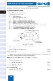
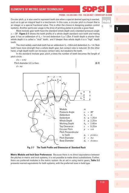
Most involute gear teeth have the standard whole depth and a standard pressure angle<br />
α = 20°. Figure 2-7 shows the tooth profile of a whole depth standard rack tooth and mating<br />
gear. It has an addendum of h a = 1m and dedendum h f<br />
≥ 1.25m. If tooth depth is shorter than<br />
whole depth it is called a “stub” tooth; and if deeper than whole depth it is a “high” depth<br />
tooth.<br />
The most widely used stub tooth has an addendum h a = 0.8m and dedendum h f = 1m. Stub<br />
teeth have more strength than a whole depth gear, but contact ratio is reduced. On the other<br />
hand, a high depth tooth can increase contact ratio, but weakens the tooth.<br />
In the standard involute gear, pitch p times the number of teeth becomes the length of<br />
pitch circle:<br />
d π = πmz<br />
⎫ ⎪<br />
Pitch diameter (d ) is then: ⎬ (2-7)<br />
⎪<br />
d = mz<br />
⎭<br />
Metric<br />
0 <strong>10</strong><br />
I<br />
R<br />
T<br />
1<br />
2<br />
3<br />
4<br />
p n<br />
p<br />
α<br />
p<br />
–– 2<br />
α<br />
5<br />
6<br />
h f<br />
h a<br />
h<br />
7<br />
Fig. 2-7<br />
d<br />
d b<br />
α<br />
Module<br />
m<br />
Pressure Angle α = 20°<br />
Addendum<br />
h a = m<br />
Dedendum h f ≥ 1.25m<br />
Whole Depth h ≥ 2.25m<br />
Working Depth h w = 2.00m<br />
Top Clearance c = 0.25m<br />
Circular Pitch p = πm<br />
Pitch Perpendicular<br />
to Tooth<br />
p n = p cos α<br />
Pitch Diameter d = mz<br />
Base Diameter d b = d cos α<br />
The Tooth Profile and Dimension of Standard Rack<br />
8<br />
9<br />
<strong>10</strong><br />
<strong>11</strong><br />
<strong>12</strong><br />
Metric Module and Inch Gear Preferences: Because there is no direct equivalence between<br />
the pitches in metric and inch systems, it is not possible to make direct substitutions. Further,<br />
there are preferred modules in the metric system. As an aid in using metric gears, Table 2-2<br />
presents nearest equivalents for both systems, with the preferred sizes in bold type.<br />
<strong>13</strong><br />
<strong>14</strong><br />
<strong>15</strong><br />
T-23<br />
A