CPU Module Installation Guide - Dynojet Research
CPU Module Installation Guide - Dynojet Research
CPU Module Installation Guide - Dynojet Research

You also want an ePaper? Increase the reach of your titles
YUMPU automatically turns print PDFs into web optimized ePapers that Google loves.
R E S E A R C H<br />
<strong>CPU</strong> <strong>Module</strong><br />
<strong>Installation</strong> <strong>Guide</strong><br />
©2001 <strong>Dynojet</strong> <strong>Research</strong>, Inc. All Rights Reserved. 010725SD<br />
<strong>Dynojet</strong> <strong>Research</strong>, Inc.<br />
200 Arden Drive<br />
Belgrade, MT 59714<br />
<br />
2191 Mendenhall Drive<br />
North Las Vegas, NV 89031<br />
P/N 98295108
Copyright<br />
This manual is copyrighted by <strong>Dynojet</strong> <strong>Research</strong>, Inc., hereafter referred to as<br />
<strong>Dynojet</strong>, and all rights are reserved. This manual is furnished under license and<br />
may only be used or copied in accordance with the terms of such license. This<br />
manual is furnished for informational use only, is subject to change without<br />
notice, and should not be construed as a commitment by <strong>Dynojet</strong>. <strong>Dynojet</strong><br />
assumes no responsibility or liability for any error or inaccuracies that may appear<br />
in this manual.<br />
Trademarks<br />
The <strong>Dynojet</strong> logo is a trademark of <strong>Dynojet</strong> <strong>Research</strong>, Inc.<br />
Any trademarks, trade names, service marks, or service names owned or<br />
registered by any other company and used in this guide are the property of their<br />
respective companies.<br />
© 2001 <strong>Dynojet</strong> <strong>Research</strong>, Inc.
TABLE OF CONTENTS<br />
Chapter 1 <strong>CPU</strong> <strong>Module</strong> <strong>Installation</strong><br />
Tools . . . . . . . . . . . . . . . . . . . . . . . . . . . . . . . . . . . . . . . . . . . . . . . . . . . . . . . . .1-1<br />
Conventions Used In This Manual . . . . . . . . . . . . . . . . . . . . . . . . . . . . . . . . . .1-1<br />
Technical Support . . . . . . . . . . . . . . . . . . . . . . . . . . . . . . . . . . . . . . . . . . . . . . .1-1<br />
<strong>Installation</strong> . . . . . . . . . . . . . . . . . . . . . . . . . . . . . . . . . . . . . . . . . . . . . . . . . . . . .1-2<br />
Removing the <strong>CPU</strong> <strong>Module</strong> . . . . . . . . . . . . . . . . . . . . . . . . . . . . . . . . . . . . . .1-2<br />
Installing the <strong>CPU</strong> <strong>Module</strong> . . . . . . . . . . . . . . . . . . . . . . . . . . . . . . . . . . . . . . .1-4<br />
<strong>CPU</strong> <strong>Module</strong> <strong>Installation</strong> <strong>Guide</strong><br />
i
TABLE OF CONTENTS<br />
ii<br />
<strong>CPU</strong> <strong>Module</strong> <strong>Installation</strong> <strong>Guide</strong>
C HAPTER<br />
1<br />
<strong>CPU</strong> MODULE INSTALLATION<br />
This document provides instructions for installing the <strong>CPU</strong> module. To ensure safety<br />
and accuracy in the procedures, perform the procedures as they are described.<br />
Document Part Number: 98295108<br />
Last Updated: 07-25-01<br />
TOOLS<br />
. . . . . . . . . . . . . . . . . . . . . . . . . . . . . . . . . . .<br />
The following tools are required to install the <strong>CPU</strong> module:<br />
• 5/64-inch allen wrench<br />
• No. 10 torx wrench<br />
CONVENTIONS USED IN THIS MANUAL<br />
The conventions used in this manual are designed to aid the user and protect both<br />
the user and the equipment.<br />
example of convention<br />
Bold<br />
description<br />
Highlights items you can select on in the software<br />
interface, including buttons and menus.<br />
The Caution icon indicates a potential hazard to the<br />
dynamometer equipment. Follow all procedures<br />
exactly as they are described and use care when<br />
performing all procedures.<br />
TECHNICAL SUPPORT<br />
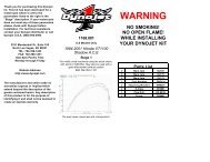
For assistance, please contact <strong>Dynojet</strong> Technical Support at 1-800-992-4993, or write<br />
to <strong>Dynojet</strong> at 2191 Mendenhall Drive, North Las Vegas, NV 89031.<br />
Visit us on the World Wide Web at www.dynojet.com where <strong>Dynojet</strong> provides state of<br />
the art technical support, on-line shopping, 3D visualizations, and press releases<br />
about our latest product line.<br />
<strong>CPU</strong> <strong>Module</strong> <strong>Installation</strong> <strong>Guide</strong><br />
1-1
CHAPTER 1<br />
<strong>Installation</strong><br />
INSTALLATION<br />
. . . . . . . . . . . . . . . . . . . . . . . . . . . . . . . . . . .<br />
This section describes procedures for removing and replacing the <strong>CPU</strong> module.<br />
Always turn the hardware stack power off before removing or making any<br />
connections.<br />
REMOVING THE <strong>CPU</strong> MODULE<br />
1 Turn the power switch off at the <strong>CPU</strong> module and unplug the power cord.<br />
2 Disconnect all of the cables from the hardware stack.<br />
atmospheric<br />
sensing module<br />
RPM module<br />
dynamometer<br />
input/output module<br />
<strong>CPU</strong> module<br />
power switch<br />
stack base<br />
Figure 1-1: Hardware Stack<br />
3 Using a No. 10 torx wrench, loosen the top right screw on the back of the <strong>CPU</strong><br />
module to release the grounding strap.<br />
grounding strap<br />
screw on <strong>CPU</strong> module<br />
Figure 1-2: Grounding Strap<br />
1-2<br />
<strong>CPU</strong> <strong>Module</strong> <strong>Installation</strong> <strong>Guide</strong>
<strong>CPU</strong> MODULE INSTALLATION<br />
<strong>Installation</strong><br />
4 Remove the cable ducts from each side of the <strong>CPU</strong> module.<br />
5 Firmly hold the stack base with one hand and carefully lift the top three modules<br />
up, as straight as possible.<br />
remove top modules<br />
cable duct<br />
Figure 1-3: Remove Cable Ducts And Top <strong>Module</strong>s<br />
6 Using a 5/64-inch allen wrench, remove the four black button-head screws (two<br />
on each side) from the stack base.<br />
7 Remove the <strong>CPU</strong> module from the stack base.<br />
button head screws<br />
Figure 1-4: Remove <strong>CPU</strong> <strong>Module</strong> From Stack Base<br />
8 Tilt the <strong>CPU</strong> module allowing the four nuts (two on each side) to slide from the<br />
module.<br />
nuts<br />
Figure 1-5: Remove Nuts From <strong>CPU</strong> <strong>Module</strong><br />
<strong>CPU</strong> <strong>Module</strong> <strong>Installation</strong> <strong>Guide</strong><br />
1-3
CHAPTER 1<br />
<strong>Installation</strong><br />
INSTALLING THE <strong>CPU</strong> MODULE<br />
Note: Examine the new <strong>CPU</strong> module for damage. Make sure the battery on the<br />
bottom of the module is properly seated. It the battery has come loose, contact<br />
<strong>Dynojet</strong>.<br />
1 Insert the nuts you removed earlier into the new <strong>CPU</strong> module (two on each side).<br />
2 Secure the <strong>CPU</strong> module to the stack base.<br />
2a Set the <strong>CPU</strong> module on the stack base.<br />
2b Line up one of the front nuts with the stack base and secure with a<br />
button-head screw.<br />
2c Line up the remaining front nut with the stack base and secure with a<br />
button-head screw.<br />
2d Cover the back openings on the <strong>CPU</strong> module and tilt the module until the<br />
nuts slide down and hit your fingers.<br />
2e Using the allen wrench, slide the nuts until they are aligned with the holes<br />
on the back of the stack base and secure with button-head screws.<br />
use the allen wrench to<br />
slide nut into place<br />
line up front nut<br />
with stack base<br />
Figure 1-6: Line Up Nuts With Stack Base<br />
3 Carefully align the top three modules on the <strong>CPU</strong> connector.<br />
Be sure to place one hand on the stack base as you are replacing the top<br />
modules in order to ground the modules.<br />
4 Gently but firmly, snap the two module sections together.<br />
5 Make sure the grounding strap slips over the top right nut on the <strong>CPU</strong> module.<br />
Note: Do not secure the grounding strap at this point.<br />
1-4<br />
<strong>CPU</strong> <strong>Module</strong> <strong>Installation</strong> <strong>Guide</strong>
<strong>CPU</strong> MODULE INSTALLATION<br />
<strong>Installation</strong><br />
6 Verify each module is being recognized.<br />
Note: Be sure to check for proper module communication before securing the<br />
grounding strap and cable ducts. This will make it easier to troubleshoot and<br />
reposition the modules if needed.<br />
6a Attach the 9-pin serial cable from the PC to the RS-232 socket on the <strong>CPU</strong><br />
module. Refer to Figure 1-8 for cable placement.<br />
6b Attach the 3-pin power plug from the power supply to the <strong>CPU</strong> module with<br />
the flat side facing down. Refer to Figure 1-8 for cable placement.<br />
6c Plug in the power supply to the power source. Turn the power switch on at<br />
the <strong>CPU</strong> module. Verify that the green power LEDs glow on each module.<br />
6d Use Dyno Find to verify each module is recognized.<br />
• Open Windows Explorer.<br />
• Double-click dynofind.exe located in the WinPEP folder (C:\WinPEP).<br />
• Click Search.<br />
• Verify each module is being recognized. Your <strong>CPU</strong> module number will<br />
be different from the one used in this example.<br />
Note: Be sure any additional modules, such as the Air/Fuel Ratio module, are<br />
being recognized by Dyno Find.<br />
recognized modules<br />
Figure 1-7: Dyno Find Window<br />
6e If the top modules are not responding, turn off the power and separate the<br />
top modules from the <strong>CPU</strong> module. Make sure all the connector pins are<br />
straight and carefully replace the top modules.<br />
6f Repeat steps 6c through 6e until all of the modules are recognized.<br />
7 Once all of the modules are recognized, turn the power off.<br />
8 Using the No. 10 torx wrench, tighten the top right screw on the back of the <strong>CPU</strong><br />
module to secure the grounding strap.<br />
9 Replace the cable ducts on both sides of the <strong>CPU</strong> module.<br />
<strong>CPU</strong> <strong>Module</strong> <strong>Installation</strong> <strong>Guide</strong><br />
1-5
CHAPTER 1<br />
<strong>Installation</strong><br />
10 Attach the cables removed earlier to the hardware stack. Refer to Figure 1-8 for<br />
cable placement.<br />
• Attach the 9-pin shielded serial cable from the PC to the RS-232 socket on the<br />
<strong>CPU</strong> module (if not already connected). Tighten the screws.<br />
• Attach the 25-pin shielded cable from the dynamometer to the Dynamometer<br />
Input/Output module. Tighten the screws.<br />
• Attach the 9-pin connector from the hand-held pendant to the Dynamometer<br />
Input/Output module. Tighten the screws.<br />
• Attach the 3-pin plug from the power supply to the <strong>CPU</strong> module with the flat<br />
side facing down (if not already connected).<br />
• If you have an Air/Fuel Ratio module (not shown), attach the cable and tighten<br />
the screws.<br />
• Be sure to attach any additional module cables you may have to the hardware<br />
stack.<br />
primary inductive<br />
pickup socket<br />
25-pin socket<br />
power LEDs<br />
9-pin, hand-held<br />
pendant<br />
9-pin, RS-232 socket<br />
3-pin power plug<br />
Figure 1-8: Attach Hardware Stack Cables<br />
11 Turn the power switch on at the <strong>CPU</strong> module and verify operation with WinPEP.<br />
1-6<br />
<strong>CPU</strong> <strong>Module</strong> <strong>Installation</strong> <strong>Guide</strong>