CPU Module Installation Guide - Dynojet Research
CPU Module Installation Guide - Dynojet Research
CPU Module Installation Guide - Dynojet Research

Create successful ePaper yourself
Turn your PDF publications into a flip-book with our unique Google optimized e-Paper software.
CHAPTER 1<br />
<strong>Installation</strong><br />
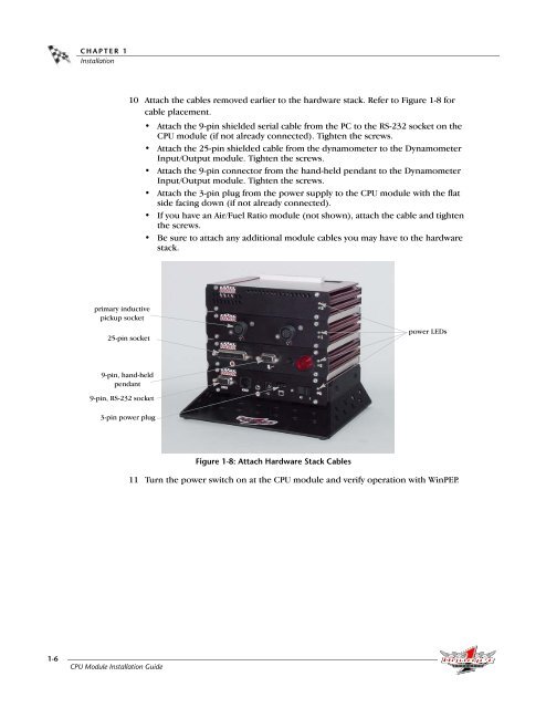
10 Attach the cables removed earlier to the hardware stack. Refer to Figure 1-8 for<br />
cable placement.<br />
• Attach the 9-pin shielded serial cable from the PC to the RS-232 socket on the<br />
<strong>CPU</strong> module (if not already connected). Tighten the screws.<br />
• Attach the 25-pin shielded cable from the dynamometer to the Dynamometer<br />
Input/Output module. Tighten the screws.<br />
• Attach the 9-pin connector from the hand-held pendant to the Dynamometer<br />
Input/Output module. Tighten the screws.<br />
• Attach the 3-pin plug from the power supply to the <strong>CPU</strong> module with the flat<br />
side facing down (if not already connected).<br />
• If you have an Air/Fuel Ratio module (not shown), attach the cable and tighten<br />
the screws.<br />
• Be sure to attach any additional module cables you may have to the hardware<br />
stack.<br />
primary inductive<br />
pickup socket<br />
25-pin socket<br />
power LEDs<br />
9-pin, hand-held<br />
pendant<br />
9-pin, RS-232 socket<br />
3-pin power plug<br />
Figure 1-8: Attach Hardware Stack Cables<br />
11 Turn the power switch on at the <strong>CPU</strong> module and verify operation with WinPEP.<br />
1-6<br />
<strong>CPU</strong> <strong>Module</strong> <strong>Installation</strong> <strong>Guide</strong>