Larkin RC Air Cooled Condenser Manual June ... - Schneider Electric
Larkin RC Air Cooled Condenser Manual June ... - Schneider Electric
Larkin RC Air Cooled Condenser Manual June ... - Schneider Electric

Create successful ePaper yourself
Turn your PDF publications into a flip-book with our unique Google optimized e-Paper software.
LARKIN AIR COOLED CONDENSERS<br />
Multi Circuiting Selection Procedure<br />
The air cooled condensers are available with more than one<br />
refrigerant circuit. The condenser will be factory assembled with<br />
the condenser coil divided into individual refrigerant circuits, each<br />
sized for its own specific application. Each circuit is supplied with<br />
its own inlet and outlet connections, individually labeled.<br />
Multi Circuit <strong>Condenser</strong> Selection<br />
Given four suction cooled compressors with conditions shown in<br />
Table 8 below. The condenser shall have 830 RPM fan motors,<br />
with two rows of fans. The condenser location is at sea level and<br />
the design ambient is 95°F.<br />
Selection Procedure<br />
Step 1: Input customer data in Table 8 in columns 1, 2, 3, 4<br />
and 5.<br />
Step 2: From Table 5, select the heat of compression factor for<br />
suction cooled compressors and input into column #6.<br />
Step 4: Calculate the design T.D. for each circuit by subtracting<br />
the ambient temperature from the circuit design<br />
condensing temperature and input into column #8.<br />
Step 3: From Table 9 obtain the refrigerant capacity factor and<br />
input into column #7.<br />
T.D. = Design Condensing Temperature - Ambient Temperature<br />
Step 5: Calculate the design THR / °T.D. for each circuit.<br />
Multiply column #5 by column #6 to calculate the THR for<br />
each circuit. Divide the result by the refrigerant correction<br />
factor, column #7 to convert the capacities to a common<br />
refrigerant. Divide the result by the design T.D., column<br />
#8 to calculate the design THR / °T.D. and input into<br />
column #9.<br />
Design THR / °T.D. = Compressor Capacity (#5) * Heat of Compressor Factor (#6)<br />
Refrigerant Capacity Factor (#7) * Design T.D. (#8)<br />
Example for circuit #1<br />
Design THR / °T.D. = 235,000 * 1.31<br />
1.0 x 15<br />
= 20,523 BTUH / °T.D.<br />
Step 6:<br />
Add the design THR / °T.D. for each circuit in column<br />
#9, to get a total of 37,734 BTUH / °T.D. Divide this total<br />
by 1,000 to get 37.7 MBH / °T.D.<br />
Step 7: From Table 2 for two rows of condenser fans with 830<br />
RPM fan motors, locate the column for R-22 capacity at<br />
1° T.D. Read down the column until you get to a<br />
capacity equal to or greater than 37.7 MBH / °T.D. This<br />
value is 38.13 which corresponds to a <strong>RC</strong>8 076. From<br />
Table 2 obtain the total number of feeds available as 42.<br />
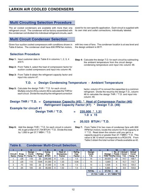
Table 8.<br />
<strong>Condenser</strong> Multi-Circuit Selection.<br />
1 2 3 4 5 X 6 ÷ 7 ÷ 8 = 9 10 11 12<br />
Design Comp. Heat of Refrig. Design No. of Actual Actual<br />
Circuit Evap. Cond. Refrig. Cap. Compress. Cap. Cond. Design Feeds Cond. Cond.<br />
Name Temp.°F Temp.°F Type BTUH X Factor ÷ Factor ÷ T.D. = THR/°TD Per Circ. T.D. Temp. °F<br />
1 +25 110 22 235,000 X 1.31 ÷ 1.0 ÷ 15 = 20,523 23 14.7 109.7<br />
2 +20 110 134A 61,000 X 1.33 ÷ 0.95 ÷ 15 = 5,693 6 15.7 110.7<br />
3 -10 105 22 31,000 X 1.46 ÷ 1.0 ÷ 10 = 4,526 5 10.0 105.0<br />
4 -20 105 22 46,000 X 1.52 ÷ 1.0 ÷ 10 = 6,992 8 9.6 104.6<br />
TOTAL = 37,734 42<br />
37,734 / 1,000 = 37.7 MBH/°TD<br />
12