Quality inspection guide - Schneider Electric
Quality inspection guide - Schneider Electric
Quality inspection guide - Schneider Electric
- No tags were found...

Create successful ePaper yourself
Turn your PDF publications into a flip-book with our unique Google optimized e-Paper software.
Means and process1. Introduction to quality <strong>inspection</strong>1.1. Justification for quality <strong>inspection</strong> 41.2. <strong>Quality</strong> <strong>inspection</strong> function 51.3. <strong>Quality</strong> <strong>inspection</strong> responsibility 51.4. <strong>Quality</strong> inspector’s profile 51.5. Necessary documents 51.6. Required human resources 51.7. Inspection diagram 62. Incoming delivery <strong>inspection</strong>2.1. Justification for the incoming <strong>inspection</strong> 82.2. Procedures 93. In-process <strong>inspection</strong>3.1. Inspection during manufacturing 103.2. Justification for the <strong>inspection</strong>during the manufacturing stage 103.3. Process 113.4. Means 114. Final <strong>inspection</strong>4.1. Final <strong>inspection</strong> process 124.2. Operating rules 134.3. Non-conformity treatment process 144.4. Conformity declaration 155. Summary of tasks after final <strong>inspection</strong> stage5.1. Customer acceptance before installation 165.2. Installation 165.3. Commissioning 163
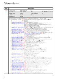
Means and process1. Introduction to quality<strong>inspection</strong>1.1. Justification for quality <strong>inspection</strong>@@Implementation of the quality process in the production plant will entailorganising the work station so as to achieve the quality target as imposed by thestandard.@@A quality <strong>inspection</strong> process has always been recommended to all our partnersand subsidiaries.@@A part of quality assurance, it is a normative obligation of the IEC 60439-1 andIEC 61439-2 standards which stipulate that three routine tests should be performedunder the scope of the quality <strong>inspection</strong> procedures to complete the type tests:__giving the equipment the TTA label (Type Tested Assembly)__and which are the panel builder’s responsibility.These three routine tests are@@<strong>inspection</strong> of the assembly@@dielectric tests and/or measurement of insulation resistance@@checking of protective measures and of the electrical continuity @of the protective circuit.Human factors@@The specificity and complexity of low voltage equipment, the numerous humanoperations, and thus risk of errors, are the principal source of mistakes in our field,and hence the main reasons for implementation of the quality <strong>inspection</strong> process.@@Each job must be checked.Cost reduction@@Manufacturing non-quality entails extra costs in term of time and money due to:__product examination,__repair,__scrapping,__impacts on delivery schedule, brand image,__etc.@@A study shows that a fault detected on a customer site can cost one hundredto one thousand times more than if it had been detected during the switchboarddesign phase (see graph below).@@The in-process checking operation and final <strong>inspection</strong> also ensure goodeconomic management of the switchboard manufacturing process.4
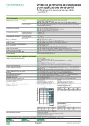
Means and process1. Introduction to quality<strong>inspection</strong>The <strong>Quality</strong> <strong>inspection</strong> therefore contributes@@to guaranteed quality of the equipment:__by preserving the company’s brand image__by guiding staff training according to the anomalies observed.@@to the safety of personnel and equipment@@to the company's profitability.1.2. <strong>Quality</strong> <strong>inspection</strong> function@@Guarantee the quality of service and protect the brand image.@@Detect and settle internal dysfunctions and thereby increase plant profitability.@@Perform <strong>inspection</strong> with respect to:__the project file and the customer's documents__<strong>Schneider</strong> and product rules__IEC standards@@Carry out acceptance tests in the customer's presence@@Perform quality follow-up and corrective actions@@Ensure information, preventive action and training for production staff@@Ensure regular calibration of <strong>inspection</strong> and production facilities.1.3. <strong>Quality</strong> <strong>inspection</strong> responsibility@@<strong>Quality</strong> <strong>inspection</strong> department__reports directly to management and is independent from manufacturing__can postpone the delivery of a project and require reworking to ensureconformity__in the event of a dispute, informs the unit manager who alone has the power todecide__is responsible for the safety of all people entering the quality <strong>inspection</strong> zone.1.4. <strong>Quality</strong> inspector’s profile@@Graduate as electrical technician (technician’s certificate)@@Versatile@@Good knowledge of <strong>Schneider</strong> equipment and devices@@Authorised to work near electric currents:__knowledge of the risk of electric current__authorisation by approved training course__basic notions of first-aid.1.5. Necessary documents@@To carry out the various checks, the quality inspector must possess a complete,updated production file of the project, including the check list, missing parts list, etc.1.6. Required human resources@ @ For an accurate and reliable quality process, quality inspectors representapproximately 10 % of workforce, i.e. 1 quality inspector for 8 to 10 fitters.5
Means and process1. Introduction to quality<strong>inspection</strong>1.7. Inspection diagramDesignProcurementManufacturing stageDesign officeReceptionistOperatorCommercialcontractDesign<strong>inspection</strong>reportProcurementorderBasic check listfor incoming<strong>inspection</strong>FrameworkAssembly planIn-process<strong>inspection</strong>specificationsBusbarAssembly planDimensional<strong>inspection</strong> reportIn-process<strong>inspection</strong>reportIn-process<strong>inspection</strong>specificationsIn-process<strong>inspection</strong>reportDevice& drawerAssembly planIn-process<strong>inspection</strong>specificationsIn-process<strong>inspection</strong>reportEnclosureAssembly planIn-process<strong>inspection</strong>specificationsIn-process<strong>inspection</strong>reportReference documentDocument to be fulfilled inExample of "In-process <strong>inspection</strong> specification"@delivered with assembly drawingIn-process control specification : FrameworkInspectionTo doDimensions of cubicleMechanical assemblyFramework combinationCheck the cubicle dimensions according to those required in the project productionfileCheck the overall assembly,the orientation and position of uprights relative to the horizontal busbar,the junction between uprights (no gap at the junction point of 2 uprights)the presence and tightening of all screwsthe presence of screws on back upright for drawer fixed part.Check presence of accessories for combinationHandling systemVerify presence of accessories for handling the cubicleGround fixing & civil engineeringVerify presence and conformity of ground fixing according to the "affaire" (job) fileBottom plate form 2 Verify presence of isulating plate on the bottom plate form 2CleannessCheck the cleanness of the assembly: no scratch, no grease6
Means and process1. Introduction to quality<strong>inspection</strong>Final<strong>inspection</strong><strong>Quality</strong> inspectorCustomeracceptanceCustomerInstallationContractorCommissioningCustomer<strong>Quality</strong> <strong>guide</strong>Installation<strong>guide</strong>Design<strong>inspection</strong>reportInstallation<strong>inspection</strong>reportCustomeracceptance reportIn-process<strong>inspection</strong>reportIn-process<strong>inspection</strong>reportIn-process<strong>inspection</strong>report<strong>Quality</strong> control @planIn-process<strong>inspection</strong>report<strong>Quality</strong> controlplanExample of "In-process <strong>inspection</strong> report"Checking programme: FrameworkIndex:Product type:Drawing No.:Cubicle No.:Project No.:Customer:Date:Checking programmeIn-process <strong>inspection</strong><strong>Quality</strong> <strong>inspection</strong>ConformityRepair Checked byChecked by Conforming RemarksObservations OK Not OKDimensions of cubicleMechanical assemblyCleannessChecking during process: fill in the grey boxFinal <strong>inspection</strong> and testing: fill in the white box7
Means and process2. Incoming delivery <strong>inspection</strong>DesignDesign officeProcurementReceptionistManufacturing stageOperatorFinal<strong>inspection</strong><strong>Quality</strong> inspectorCustomeracceptanceCustomerInstallationInstallatorCommissioningCustomerCommercialcontractDesign<strong>inspection</strong>reportProcurementorderBasic check listfor incomming<strong>inspection</strong>Dimensional<strong>inspection</strong> reportFrameworkAssembly planIn-process<strong>inspection</strong>specificationsIn-process<strong>inspection</strong>reportBusbarAssembly planIn-process<strong>inspection</strong>specificationsIn-process<strong>inspection</strong>reportDevice& drawerAssembly planIn-process<strong>inspection</strong>specificationsIn-process<strong>inspection</strong>reportEnclosureAssembly planIn-process<strong>inspection</strong>specificationsIn-process<strong>inspection</strong>report<strong>Quality</strong> <strong>guide</strong>Design<strong>inspection</strong>reportIn-process<strong>inspection</strong>reportIn-process<strong>inspection</strong>reportIn-process<strong>inspection</strong>reportIn-process<strong>inspection</strong>report<strong>Quality</strong> control @planInstallation<strong>guide</strong>Installation<strong>inspection</strong>reportCustomeracceptance report<strong>Quality</strong> controlplan@@Applicable to external and internal products and assemblies.@@In the case of sub-assemblies and internally manufactured products, an internalprocedure could be used to perform a final <strong>inspection</strong> of one process, combinedwith incoming <strong>inspection</strong> of another.2.1. Justification for incoming <strong>inspection</strong>@@As a final stage before the assembly process, this quality <strong>inspection</strong> is asignificant part of the final quality of the job and will ensure its profitability.@@The reason for implementing the incoming <strong>inspection</strong> process is to ensure thatthe received materials and components comply with:__the specifications indicated in the order form (colours, etc.)__standard__product specifications__good practice rules.8
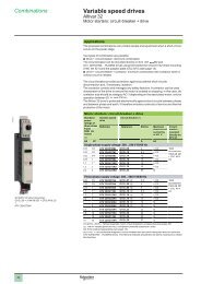
XYZMeans and process2. Incoming delivery <strong>inspection</strong>2.2. ProceduresVerification@@Quantity@and@appearance@<strong>inspection</strong>@of@products@could@be@performed@by@the@receiving@offi@cer@according@to@the@"Basic@checklist@for@incoming@<strong>inspection</strong>".@@<strong>Quality</strong>@checking@should@be@done@by@the@quality@inspector.@@In@cases@of@large@product@volumes,@this@operation@could@be@done@on@a@sample.@@If@the@drawing@of@the@component@to@be@inspected@includes@a@dimensional@warning@! ,@the@quality@inspector@shall@check@the@dimensions@on@5@samples.25±0.25 !Example@@All@incoming@items@should@be@received@and@stored@in@such@conditions@that@they@will@not@be@damaged@untill@their@fi@nal@installation.Non-conformity processing@@All@non-conforming@products@shall@be:_@confi@ned@in@a@separate@location_@registered@as@a@non-conforming@product@and@clearly@identifi@ed.@@@All@precautions@should@be@taken@to@prevent@their@repetition.Basic checklistfor incoming <strong>inspection</strong> of sheet metal partsThe type of material is right Aluminium Steel Stainless Plastic ColorThe component looks like the drawing and the 3D view all shapes and holes exist the component is bent in the correct side all cut edges are straight,without stairs or burs no deformation due to punching sub-assembly is consistentwith the bill of materialChecking programme: manufactured parts checking cardProduct type:Drawing No.:Quantity:Dimensions to be measured on 5 samplesDimesion to becheckedLocationParts or lot checked1 2 3 4 5The coating is well doneon visible sides: no grains no tears no craters no scratchoverall: adherence uniformityGrainCraterNot OKNot OKThe dimensions identified by ! are measured on 5 samplesComments checking card is writtenPurpose of the document:This document lists the basic checks to be performed in orderto ensure the quality of the switchboard manufactured parts(see the "Blokset Transfer File" for further details).2010-05☐ Approved☐ RejetedDate: / /Signature:9
Means and process3. In-process <strong>inspection</strong>DesignDesign officeProcurementReceptionistManufacturing stageOperatorFinal<strong>inspection</strong><strong>Quality</strong> inspectorCustomeracceptanceCustomerInstallationInstallatorCommissioningCustomerCommercialcontractDesign<strong>inspection</strong>reportProcurementorderBasic check listfor incomming<strong>inspection</strong>Dimensional<strong>inspection</strong> reportFrameworkAssembly planIn-process<strong>inspection</strong>specificationsIn-process<strong>inspection</strong>reportBusbarAssembly planIn-process<strong>inspection</strong>specificationsIn-process<strong>inspection</strong>reportDevice& drawerAssembly planIn-process<strong>inspection</strong>specificationsIn-process<strong>inspection</strong>reportEnclosureAssembly planIn-process<strong>inspection</strong>specificationsIn-process<strong>inspection</strong>report<strong>Quality</strong> <strong>guide</strong>Design<strong>inspection</strong>reportIn-process<strong>inspection</strong>reportIn-process<strong>inspection</strong>reportIn-process<strong>inspection</strong>reportIn-process<strong>inspection</strong>report<strong>Quality</strong> control @planInstallation<strong>guide</strong>Installation<strong>inspection</strong>reportCustomeracceptance report<strong>Quality</strong> controlplan3.1. Inspection during manufacturing@@To ensure the conformity of the product or sub-assembly with the expectedneeds, the quality assurance programme may recommend the implementation ofa specific <strong>inspection</strong> procedure. Done on parts of an assembly or at the end ofvarious assembly operations.@@The following diagram represents the operations on which in-process <strong>inspection</strong>sare carried out and the main items concerned by incoming quality <strong>inspection</strong>.Design Framework BusbarassemblyDeviceassemblyWiringEnclosureCopperbarsDevicesSheet metal3.2. Justification for <strong>inspection</strong>during the manufacturing stageThe reasons for performing <strong>inspection</strong> during the manufacturing process are:@@the complexity of some equipment systems. It could be necessary to perform aquality <strong>inspection</strong> process during manufacturing to ensure the conformity of partsor assembly stages due to:__difficulty of access: current transformer, bar characteristics, connections,installation, etc.;__the time (profitability) needed for the final inspector to remove some covers orother parts;@@the will to involve and motivate the staff for the quality of their work;@@the workshop organisation;@@existence of dedicated assembly line for frame, busbars, functional units(withdrawable, disconnectable, plug-in, fixed);@@presence of a device adaptation work station;@@mass produced manufacturing system.10
Means and process3. In-process <strong>inspection</strong>3.3. ProcessInspection during the manufacturing stage could be described by the followingprocess.Inspection during the manufacturing stage.@@This operation involves carrying out checks at different stages of the assemblyprocess:__<strong>inspection</strong> done at the end of each key manufacturing step (frameworkassembly, busbar installation, device & drawer mounting, wiring, enclosureassembly) is part of the operators' work. Each operator must fill in an "In-process<strong>inspection</strong> report"__quality inspectors have responsability for overseeing and compiling all "Inprocess<strong>inspection</strong> reports".Continuous <strong>inspection</strong>@@The assembly operations require constant observance of good practice rules.@@Due to this, this procedure involves carrying out checks throughoutmanufacturing in the form of operator or project supervisor checks.@@It will make them responsible for the quality of their work.@@These checks should always be validated by the final <strong>inspection</strong> inspectors.Notice: The cleaning process is an integral part of the checking operations andshould be performed during and at the end of the manufacturing process andregistered on the check list. (i.e.: Okken or Blokset busbar compartment).3.4. Means@@The instructions (In-process <strong>inspection</strong> specifications) provided with assemblydrawings enable these checks to be formally defined on check list reports.@@One check list is commonly dedicated to each manufacturing stage, and locatedon the cubicle frame.@@The fitter should fill in the check list dedicated to his manufacturing stage to allowthe quality inspector to verify that all the points have been checked and that theprocedures have been implemented.@@These checklist reports are used to log the status of the <strong>inspection</strong>s performed.@@The same forms are finally validated by the quality inspector during the final<strong>inspection</strong> stage.N.B.: Despite the operator checks performed for each operation, final <strong>inspection</strong> isalways necessary, as stipulated by the IEC 60439-1 and IEC 61439-2 standards.11
Means and process4. Final <strong>inspection</strong>DesignDesign officeProcurementReceptionistManufacturing stageOperatorFinal<strong>inspection</strong><strong>Quality</strong> inspectorCustomeracceptanceCustomerInstallationContractorCommissioningCustomerCommercialcontractDesign<strong>inspection</strong>reportProcurementorderBasic check listfor incomming<strong>inspection</strong>Dimensional<strong>inspection</strong> reportFrameworkAssembly planIn-process<strong>inspection</strong>specificationsIn-process<strong>inspection</strong>reportBusbarAssembly planIn-process<strong>inspection</strong>specificationsIn-process<strong>inspection</strong>reportDevice& drawerAssembly planIn-process<strong>inspection</strong>specificationsIn-process<strong>inspection</strong>reportEnclosureAssembly planIn-process<strong>inspection</strong>specificationsIn-process<strong>inspection</strong>report<strong>Quality</strong> <strong>guide</strong>Design<strong>inspection</strong>reportIn-process<strong>inspection</strong>reportIn-process<strong>inspection</strong>reportIn-process<strong>inspection</strong>reportIn-process<strong>inspection</strong>report<strong>Quality</strong> control @planInstallation<strong>guide</strong>Installation<strong>inspection</strong>reportCustomeracceptance report<strong>Quality</strong> controlplan@@Final <strong>inspection</strong> guarantees operation and conformity of products in accordancewith applicable drawings and standards. It is performed by the unit’s quality<strong>inspection</strong> department.@@One document per project formulating the customer’s requirements andtranscribing the specification is used for the checking phases during assembly andfor final <strong>inspection</strong>. It forms the first reference document (production file).@@@The following table gives you an idea of the average time required to perform afinal <strong>inspection</strong> according to the type of switchboard to be inspected.@@The following information is given as an average % of assembly process.Switchboard Simple ComplexPCC 3% 8%MCC 4% 10%@@4.1. Final <strong>inspection</strong> processFinal <strong>inspection</strong> takes place as follows@@Carry out the conformity check by compiling the "In-process <strong>inspection</strong> reports".@@Conduct the final <strong>inspection</strong> tests.@@Modify the production file by adding any necessary annotations (throughouttesting).@@List all the non conformities:__by noting all the faults or modifications observed;__by drafting a list of missing parts.@@Ensure reworking for conformity.@@Point out any areas of dispute between customer and supplier.@@Ensure that the design documents have been properly corrected, @by checking final version status and updating.@@Ensure that all the check lists have been filled in.@@Draft and record the quality control plan.@@Sign the quality control plan and other documents.@@If customer acceptance is scheduled, receive the customer and/or hisrepresentative in the quality <strong>inspection</strong> zone.@Sign the "<strong>Quality</strong> control plan" after customer acceptance.@@Archive the documents.12
Means and process4. Final <strong>inspection</strong>List of the various final <strong>inspection</strong> tests:Conformity checksThese checks consist of validating all "In-process <strong>inspection</strong> reports":@@framework@@busbar@@device and drawer@@enclosure.Mechanical checksThese checks consist of testing proper operation of the mechanisms and manualcontrols, the sturdiness of the switchgear, etc.<strong>Electric</strong>al checks@@Operating tests@@Dielectric withstand@@<strong>Electric</strong>al continuity of protection circuits@@Insulation resistance.@@4.2. Operating rules@@The operating rules can be modelled using the following diagram.13
Means and process4. Final <strong>inspection</strong>4.3. Non-conformity treatment process@@The following diagram describes the various possible cases of treatment of nonconformities.During the final <strong>inspection</strong> operations, any errors detected must be recorded on a"non-quality record board" and all non conformities corrected.E.g.: type of table.Non-quality record boardCorrective actionLocation /Type of faultBBassemblyCabling PerformedbyTimeCabling error b Jean 5 minSignatureBusbar support missing b Alain 1 hour14
Means and process4. Final <strong>inspection</strong>4.4. Conformity declaration@@On completion of final <strong>inspection</strong>, the quality inspector's signature declaringconformity of the equipment should be affixed on the identification label placed onthe drawers and cubicles.@Panel builder“leneX0 000 ileTel : XX XX XX XX XXFax : XX XX XX XX XX”“<strong>Quality</strong> <strong>inspection</strong>Checked by:”ConformityDATE: …..../……./.…… frame ConformityJob No.: ……….…....….. device Mechanical checkSwitchboard: ………… power <strong>Electric</strong>al testCubicle: ………………. auxiliairies Dielectric testEquipment No./location:……………………………Rating: ………………..Design No.: ……………finishingProtective measurescheckInsulation testIndex: ………………@@Only fully inspected cubicles can be dispatched.@@A label, resembling the one below, is used to identify them before packaging.Final <strong>inspection</strong> sheetReady for dispatchClient: …………………………………… Purchase order No. ………………Switchboard designation: …………...<strong>Quality</strong> control plan No.: …………...Design file reference …………...Issue on: …………<strong>Quality</strong> InspectorName: ……………………Signature:Date:......./......./.......<strong>Quality</strong> ManagerName: ……………………Signature:On request, and depending on the product's destination, it is also uo to the quality<strong>inspection</strong> manager to establish a mark declaration of conformity (e.g. CE) whichcertifies that the industrial product complies with the technical directives andobligations incumbent on the product manufacturer.15
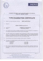
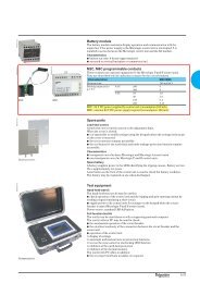
A: IN SHOP INSPECTION H : HOLD POINTW1: FULL WITNESS INSPECTION (during FAT*) M : MONITORINGXXXXXXX0 dd/mm/yyyy W2 : SPOT WITNESS INSPECTION (during FAT*) 1 = 100 %*FAT : Factory Acceptance Tests 2 = 5 %QUALITYACTIVITYCHARACTERISTICS TO BE PROCEDURE ACCEPTANCE REFERENCE CONTROL POINTS - BY TYPE AND EXTENTACTIVITYEPC orThird PartyPurchaserNo. VERIFIED REFERENCE CRITERIA DOCUMENT VENDOR if applicable inCustomerif applicable inthe projectthe project1.2 Presence of distinctive Blokset features:* <strong>Schneider</strong> <strong>Electric</strong> logo on each cubicle* handling eyebolts* Danger (triangle) logo on each plate or door covering conductors1.3 Compliance of colour with Front View Diagram indication, with absence ofscratches and stainsPRESENCECOMPLIANCEFront View Diagram1.8 IP degree construction compliance COMPLIANCE Assembly Drawings1.10 Strict use of <strong>Schneider</strong> <strong>Electric</strong> genuine busbar supporting parts (horizontalProof of purchase tobusbar comb supports, vertical drawers cubicle busbar supports, drawerCOMPLIANCE<strong>Schneider</strong> <strong>Electric</strong>Aplugs, drawer auxiliary contacts)1.11 Visual check of all power connections Marked with solid red varnishA(paint), with no cracking1.12 Drawers & other functional units interlocks:Single Line Diagram anddrawers interchangeability interlockInterlocking Diagramdrawers insertion/extraction interlockCOMPLIANCEAACB insertion/extraction interlockMechanical ACB source switching interlock2 VERIFICATION OF ELECTRICAL FUNCTIONALITY COMPLIANCE / IN SHOP INSPECTION2.1 Compliance of LV devices identification & tagging COMPLIANCE Wiring diagrams A2.2 Compliance of wiring COMPLIANCE Wiring diagrams ACompliance of protection & automatic functionalities, local/remote controls,Wiring diagrams2.3COMPLIANCEAtimings, etc.Functional schemes2.4 Power circuits dielectric test NO FLASHOVER / SPARK IEC60439-1 A2.5 Power circuits insulation test NO FLASHOVER / SPARK IEC60439-1 A2.6 Ground continuity on switchboard ELECTRICAL CONTINUITY IEC60439-1 AAAMeans and process5. Summary of tasks afterfinal <strong>inspection</strong> stageDesignDesign officeProcurementReceptionistManufacturing stageOperatorFinal<strong>inspection</strong><strong>Quality</strong> inspectorCustomeracceptanceCustomerInstallationContractorCommissioningCustomerCommercialcontractDesign<strong>inspection</strong>reportProcurementorderBasic check listfor incomming<strong>inspection</strong>Dimensional<strong>inspection</strong> reportFrameworkAssembly planIn-process<strong>inspection</strong>specificationsIn-process<strong>inspection</strong>reportBusbarAssembly planIn-process<strong>inspection</strong>specificationsIn-process<strong>inspection</strong>reportDevice& drawerAssembly planIn-process<strong>inspection</strong>specificationsIn-process<strong>inspection</strong>reportEnclosureAssembly planIn-process<strong>inspection</strong>specificationsIn-process<strong>inspection</strong>report<strong>Quality</strong> <strong>guide</strong>Design<strong>inspection</strong>reportIn-process<strong>inspection</strong>reportIn-process<strong>inspection</strong>reportIn-process<strong>inspection</strong>reportIn-process<strong>inspection</strong>report<strong>Quality</strong> control @planInstallation<strong>guide</strong>Installation<strong>inspection</strong>reportCustomeracceptance report<strong>Quality</strong> controlplan<strong>Quality</strong> Control PlanDOCUMENT NUMBERREVISION NUMBER DATE AR: APPROVAL REQUIRED T/C : TEST CERTIFICATE REQUIRED1 GENERAL VERIFICATION OF COMPLIANCE / IN SHOP INSPECTION1.1 Compliance of quantity, order and tagging of cubicles. COMPLIANCE Single Line Diagram A1.4 Switchboard overall dimensions and functional units dimensions COMPLIANCE Front View Diagram A1.5 Doors opening & locking functionality FUNCTIONAL A1.6 Keylocking system compliance COMPLIANCE Interlocking Diagram A1.7 Drawers mechanical insertion/extraction/latching functionality FUNCTIONAL A1.9 Compliance of equipment and switchgear type and rating COMPLIANCE Single Line Diagram AVENDOR:RemarksCERTIFIED COMPLETE :DATE:5.1. Customer acceptance beforeinstallation@@After final <strong>inspection</strong> and according to the contract clauses, the <strong>Quality</strong> Inspectormay perform a check on the project accompanied by a sales engineer and thecustomer or his representative. During the acceptance procedure, the customermakes sure that the specifications have been complied with.N.B.:The procedures mentioned in this <strong>guide</strong> are given as an indication.@@After final <strong>inspection</strong>, the following are required:__Check that all the boxes of the checking programme have been filled in.__Check any reworks noted on the "non-quality record board" and sign in therelevant boxes.__Draft and record the quality control plan.__Note the quality control plan registration number on the checking programme.__Ask the quality manager to validate the report (the final <strong>inspection</strong> shouldbe signed by the customer or his representative after customer acceptance<strong>inspection</strong>).__Draft and record the delivery sheet. @@5.2. Installation@@See "Installation <strong>guide</strong>".@@CUSTOMER'S ACCEPTANCE REPORT5.3. Commissioning@@Fill in and sign the costumer's acceptance report with the costumer.Customer Project Switchboard Project No.Participants : Other concerned people :Plant's Manager, Sales Manager, <strong>Quality</strong> Manager, Design office ManagerDispatching Manager QI : Mr......................DOF : Mr......................N° RecordSTAGE OBSERVATIONS AND ACTIONS RESP.* VISA QITime spent for resamption Design Office Assembling QICustomer's representative <strong>Quality</strong> attendant Salesman Final acceptance date of shippingDate : Date :Date : Date :Name : Name : Name : Signature Qual. Manager : date of delivelySignature : Signature : Signature :Resp.* : A Design Office, Production, = Automatism, D = S = Shipping, P = QI = <strong>Quality</strong> Inspection page /16
Means and processNotes17
Detailed instructions6. Performing in-process <strong>inspection</strong>6.1. Design 216.2. Framework 216.3. Busbars 216.4. Device and drawer 236.5. Enclosure 267. Performing final <strong>inspection</strong>7.1. First routine test: <strong>inspection</strong> of the assembly,conformity check 287.2. Second routine test:protective measures & protective circuit 327.3. Third routine test: dielectric test 337.4. Pre-dispatching checks 3419
Detailed instructions6. Performing in-process<strong>inspection</strong>DesignDesign officeProcurementReceptionistManufacturing stageOperatorFinal<strong>inspection</strong><strong>Quality</strong> inspectorCustomeracceptanceCustomerInstallationContractorCommissioningCustomerCommercialcontractDesign<strong>inspection</strong>reportProcurementorderBasic check listfor incoming<strong>inspection</strong>Dimensional @<strong>inspection</strong> reportFrameworkAssembly planIn-process<strong>inspection</strong>specificationsIn-process<strong>inspection</strong>reportBusbarAssembly planIn-process<strong>inspection</strong>specificationsIn-process<strong>inspection</strong>reportDevice& drawerAssembly planIn-process<strong>inspection</strong>specificationsIn-process<strong>inspection</strong>reportEnclosureAssembly planIn-process<strong>inspection</strong>specificationsIn-process<strong>inspection</strong>report<strong>Quality</strong> <strong>guide</strong>Design <strong>inspection</strong>reportIn-process<strong>inspection</strong>reportIn-process<strong>inspection</strong>reportIn-process<strong>inspection</strong>reportIn-process<strong>inspection</strong>report<strong>Quality</strong> control @planInstallation<strong>guide</strong>Installation<strong>inspection</strong>reportCustomer @acceptance<strong>Quality</strong> controlplanOkken local adaptation rulesCan do (in autonomy)WARNINGWarning: authorized and forbidden operations are defined in theAdaptation rules. They must be scrictly followed.You can adapt the enclosure panels (front and rear panels) to end-user needs,ensuring the phase-to-phase & phase-to-ground clearances remain the same as inOkken (14mm minimum)Why?This does not have any impact on IEC60439-1 TTA characteristics of Okken (short circuit,thermal rise, clearance/creepage distances)You can adapt outgoing power connection by increasing their length or cross section(to have more cables connectable), ensuring the phase-to-phase & phase-to-groundclearances remain the same as in Okken (14mm minimum)Why?Increasing the connection dimensions, with due care with clearances, will have a slightlypositive effect on thermal rise. This does not affect negatively the IEC60439-1 type testedperformance.You can increase the size ofb functional unit (feeder, drawer, incomer)b busbarb power connectionb cablefrom Okken DVD Panelbuilder Tools, without changing its defined power/currentrating.Why?Increasing the dimensions of functional unit/busbar/power connection/cable, with duerespect of rules expressed in Okken Panelbuilder Tools (last version), will have a slightlypositive effect on thermal rise. This does not affect negatively the IEC60439-1 type testedperformance.Reminder@@The purpose of in-process <strong>inspection</strong> is to ensure product conformity after eachmanufacturing operation.@@This process concerns all the manufacturing operations done by the workshopoperators.Composition@@One check list sheet for each manufacturing stage is completed for each cubicleand/or functional unit (depending on the manufacturing process).@@These documents are used by both the operators and the quality inspectors(see model check list in appendix).@@These are used from the first manufacturing phase through to final <strong>inspection</strong>.@@These check lists should mention:__the designation of each point to be controlled__the operator's identification and the checking period.Process@@After each stage, the operator checks and declares the product in conformity bysigning this follow-up check list sheet and noting any observations.@@On completion of the <strong>inspection</strong>s, a copy of this sheet could be archived.20
Detailed instructions6. Performing in-process<strong>inspection</strong>6.1. DesignSwitchboard characteristics@@Check the protection index required in the project production file.@@Check that the corrosion resistance required in the project production file istaken in account.@@Check the form partitioning level.@@Check the organisation of spares.@@Make sure that separate equipment delivery is defined.Cubicle characteristics@@Check that the dimensions, number and layout of cubicles are in accordancewith the layout and the civil engineering works specified in the projectproduction file.@@Check that the incoming cable cut-outs comply with the incoming cables'characteristics (section number, position).Busbar characteristics@@Check the environmental installation (temperature, humidity) specificationrequired in the project production file.@@Check that the horizontal and vertical busbar cross-sections are in accordancewith the short-circuit and/or peak current.@@Check that busbars are in conformity with the corrosion resistance required inthe project production file.@@Make sure that the type of busbar coating is defined.Device and drawer characteristics@@Make sure that device characteristics defined comply with the project productionfile and derating tables.@@Make sure that the jaw characteristics comply with the corrosion resistance.@@Check that the mismatch coding is defined.Wiring characteristics@@Validate the single-line diagram.@@Check that BUS architecture rules are complied with (cf. wiring <strong>guide</strong>)6.2. FrameworkDimensions of cubicle@@Check the cubicle dimensions (height, width, length and depth) @by measuring and comparing them with those required in the project @production file.Mechanical assembly@@Check the overall assembly, frame position (top, bottom), the presence andlocation of the screws required for assembling and joining the cubicles, bottomplate, mounting plate, etc.@@Check that screws are properly tightened.Cleanness@@Check the cleanness of the framework assembly: no grease, no scratch, etc.6.3. BusbarsType and characteristics@@Check the bars' characteristics according to the type of equipment, @the project specifications and the project design.Cross-section@@According to nominal current (In), short-circuit current and/or peak current, IP,circuit-breaker breaking time, etc.@@Check that the cross-section corresponds to that shown in the project productionfile and product documentation.Coating@@Check the type of busbar coating (bare copper, tin-coated, sheathed busbars,epoxy paint, silver-plating, nickel, etc.).21
Detailed instructions6. Performing in-process<strong>inspection</strong>Layout and installationBusbars@@Check their position (horizontal, vertical, top, etc).@@Check that the layout or arrangement of the busbars does not obstruct therouting of customer cable.@@Ensure the extension possibilities of the busbars according to specific features.Supports@@Check the spacing, fastening, characteristics and number of busbar supports.Refer to technical documents, switchboard characteristics, etc.@@Type of supports:__Check their type and characteristics (material) referring to the switchboardcharacteristics.__Check the alignment of the support, and presence of deformation due to extratorque applied to the fixing bolt.Bending radius and bar alignment@@Check that the bending radius and angle are in accordance with the drawing. Ifspecified, use the jig to check dimensions.@@Check the perfect alignment of the various bar assemblies:__Ensure good positioning in the support;__Make insertion of the connection bolt easier.Busbar junctions and links@@Joint cross-sections@@Characteristics and number@@Check positioning and accessibility of the joint screws@@Insulating distances versus frame, form partition, etc.@@Bar overlapping surfaces: H = th. x n.@@For all non-standard bar connections done under supervision of the fitter, anoverlapping height equal to 5 times the thickness of the derived busbar must beallowed for order to obtain a suitable connection.Contact surfaces@@<strong>Quality</strong> of drilling/punching and surface finish (no burr or cutting deformations onthe conductors, no oil stains, etc.).@@Correspondence between the hole diameter and bolt.Bolt characteristics@@Check the bolt type (in accordance with the product specifications), @quality: class 8/8, stainless steel, etc.Installation and tightening torque@@Bolt insertion method (insulating distance), length of bolt, etc.@@Presence, position and type of washer.@@Tightening torque in accordance with bolt, devices and other part characteristics.Consult the product and devices documentation.@@Presence of varnish certifying tightening to correct torque.@@In case of doubt:__Number of threads protruding from the nut, for connections of the same type,differs on screws of the same length.__Contact washers excessively crushed or moving, carry out a sampling check.If a number of faults are detected, ask the person responsible for assembling theswitchboard to verify all its connections.Clearances@@Shortest distance in the air between two live conductors or between liveconductors and exposed conductive parts.__14 mm for 12 kV impulse voltage (main Masterpact busbar)__8 mm for 8 kV impulse voltage (Compact)__5.5 mm for 6 kV impulse voltage (Multi 9).@@The IEC 60439-1 and IEC 61439-2 standards stipulate the minimum clearancesrequired to withstand impulse voltage up to 2000 m above sea level.@@Pollution degree 3.22
Detailed instructions6. Performing in-process<strong>inspection</strong>Creepage distances@@Shortest distance along an insulated material surface between two liveconductors or between live conductors and exposed conductive parts.__16 mm for rated insulation voltage 1000 V AC and DC (main busbar Masterpact)__12.5 mm for rated insulation voltage 750 V AC and DC (Compact)__8 mm for rated insulation voltage 500 V AC and DC (Multi 9).@@See IEC 60439-1 and IEC 61439-2 table 16.@@Pollution degree 3, Material group 3a.Marking and phase order@@Check phase labelling type conformity.@@Check that phase order (phases 1, 2, 3, neutral and PE) is complied withaccording to the product specifications.Cleanness@@After busbar installation, ensure that no foreign bodies are lost in the barscompartment.@@In particular in the case of access difficulties.6.4. Device and drawerConformity of devicesDevice characteristics@@Type, rating@@Breaking capacity and number of poles@@Masterpact terminal pad characteristics and installation (according to product).Inspection to be performed prior to installation in the cubicle.Toroïds@@Check the technical data of each toroid. Also ensure the correct mountingdirection: the arrow shows the current direction.Current transformer@@Check the technical data of the current transformers together with the installationdirection.@@Check the correspondence between the current transformer and the associateddevice, ammeter, etc. Ensure that the current delivered by its secondary circuit iscompatible with the associated device.@@Check compliance with clearances between the fastenings and the secondaryconnecting screws of the current transformer relative to live conductors or metalparts.@@Check whether the current transformers are well secured on the conductor.Shunt@@Check the connection between the shunt and the measuring instrument.Safety perimeters@@Check the circuit-breaker safety perimeters, referring to their installation <strong>guide</strong>s.@@No devices, equipment or bundles should be located in the safety perimeter.MountingContact surfaces@@<strong>Quality</strong> of drillings/punching and surface finish (no burr or cutting deformationson the conductors, no oil stains, etc.).@@Correspondence between the hole diameter and bolt.@@Bar overlapping surfaces: H = th. x n.@@For all the non-standard bar connections done under supervision of the fitter, anoverlapping height equal to 5 times the thickness of the derived busbar must beallowed for in order to obtain a suitable connection.@@Avoid problems (flexion, torsion, etc.) due to incorrect busbar positioning ondevices or terminal pad connections.Bolt characteristics@@Check the bolt type (in accordance with the product specifications), @quality: class 8/8, stainless steel, etc.23
Detailed instructions6. Performing in-process<strong>inspection</strong>Installation and tightening torque@@Bolt insertion method (insulating distance), length of bolt, etc.@@Check the Linergy sliding bolt position.@@Presence, position and type of washer.@@Tightening torque in accordance with bolt, devices and other parts'characteristics. Consult the product and devices documentation.@@Presence of varnish certifying tightening to the correct torque.@@In case of doubt:__Number of threads protruding from the nut, for connections of the same type,differs on screws of the same length.__Contact washers excessively crushed or moving, carry out a sampling check.If a number of faults are detected, ask the person responsible for assembling theswitchboard to verify all the connections.Clearances@@Shortest distance in the air between two live conductors or between liveconductors and exposed conductive parts:__14 mm for 12 kV impulse voltage (main busbar Masterpact)__8 mm for 8 kV impulse voltage (Compact)__5.5 mm for 6 kV impulse voltage (Multi 9).@@The IEC 60439-1 and IEC 61439-2 standards stipulate the minimum clearancesrequired to withstand impulse voltage up to 2000 m above sea level.@@Pollution degree 3.Creepage distances@@Shortest distance along an insulated material surface between two liveconductors or between live conductors and exposed conductive parts:__16 mm for rated insulation voltage 1000 V AC and DC (main busbar Masterpact)__12.5 mm for rated insulation voltage 750 V AC and DC (Compact)__8 mm for rated insulation voltage 500 V AC and DC (Multi 9).@@See IEC 60439-1 and IEC 61439-2 Table 16.@@Pollution degree 3, Material group 3a.WiringTo be checked according to the device and switchboard characteristics.Flexible bar characteristics and installation@@Check characteristics and cross-section.@@Radius of curvature of the flexible bars (at least once times bar thickness).Manual bending operations are recommended to avoid damaging the bar insulator.@@In the event of a superimposed flexible bar installation, ensure that insulatingspacers are placed between the conductors to provide proper ventilation.Binding and cable trunking@@Check that the characteristics and number of bindings used match the electrodynamicforce that could affect the assembly in case of short circuit.@@No direct binding on metal parts. If necessary fit an insulating wedge.@@Check connections: presence of thick flat washer and contact washer.@@Maximum cable size 6 mm² in cable trunking.__Ensure that the spare space in the cable trunking is approximately 30 %; @cable fasteners should preferably be made of insulating accessories (e.g.polycarbonate screws or rivets).__The maximum centre-to-centre distance between two trunking fasteners mustnot exceed 600 mm.Cable characteristics@@Cross-section of power and auxiliary conductors: check cross-sections withreference to the switchboard specifications and product documentation.@@Type and colours.@@Nature of cables: <strong>Schneider</strong> recommends use of U 1000 V insulation with aninsulation temperature resistance of < 105°C (self-extinguishing).@@Using these cables, we meet class 2 requirements, so these cables may besecured directly on metal supports.Cables installation@@Protection of cables:__Check that the cables do not run near sharp edges, moving parts, against orbetween exposed live parts, air blast areas, etc.__No cables should be inserted in ventilation grille hole or mechanical fixing holes.@@Radius of curvature: Ensure that the cable radius of curvature is roughly 6 to 8times cable diameter.24
Detailed instructions6. Performing in-process<strong>inspection</strong>@@Number of cables per strand:@Refer to the switchboard assembly and installation <strong>guide</strong>.@@Separating the strands:@Check that the power and control strands are separated as well as the strandsreceiving an auxiliary voltage of more than 500 V AC and the DC circuit andcommunication network (cf. Communication wiring <strong>guide</strong>)@@Cable fixing:@Make sure that the conductors are fastened in accordance with theircharacteristics, size and network short circuit withstand. Check collarcharacteristics.@@Non-protected active conductors__Ensure that cables not protected by short-circuit devices are installed safelyalong their entire path.__Separated bundle, no risk of mechanical damage, safe connection, etc.Cable connections@@Three types of <strong>inspection</strong> are performed according to the connections:__Visual <strong>inspection</strong> (A) of:--the crimping recess (quality, pressure, etc.);--the correspondence between the lug or terminal and the cable section;--the position of the conductor core in the lug shaft, and proper cable insertion;--the bolt diameter relative to the lug fixing hole;--the quality of the cable insulation and strands (no damage during cableinstallation or wire stripping operation).__Mechanical <strong>inspection</strong> (B) by manual pulling (performed by random sampling).__Verification (C) of:--presence and direction of contact washers;--presence of varnish certifying tightening to the right torque (on visibleconnections) or use of torque nuts.@@The following table gives the <strong>inspection</strong>s to be performed according to the typeof connection used:where A, B, C stand for the various <strong>inspection</strong> types.A = visual <strong>inspection</strong>B = mechanical <strong>inspection</strong>C = checking presence and positioning.Connections Power Other circuitsJaws and auxiliaries pins A + B A + BLugs A + C B + CClips - A + BCable connectors A BTerminals B + C BScrews C C@@Connection stresses and fastening:__Check that the lugs match with the connector type.__Be sure that the cables are properly inserted in the terminal.__Reminder: Make sure that the crimping tools are calibrated.Test@@It is recommended to use the drawer test equipment for mechanical andelectrical testing of each drawer (cf. Industrial <strong>guide</strong>).Manual operation of equipment@@Manoeuvre the manual mechanisms of the devices, to ensure their properoperation.@@Check the operation of the functional units based on drawers, disconnectable,plug-in on base or chassis version.Equipment fastening@@Check the fastening of the devices on the drawers, on Polyfast (<strong>inspection</strong>during manufacturing process), on mounting plates, on doors, etc.@@Check that they are correctly fitted and that all the necessary screws ormiscellaneous additional items are present.@@Special attention should be paid to:__assembly compliance with functional dimension tolerances;__jaw installation and validation in the check list.__Check that the auxiliary blocks are correctly identified and assembled and thatthe mechanical assemblies remain free to move.25
Detailed instructions6. Performing in-process<strong>inspection</strong>Mechanical operation@@To be checked:__Installation and operations of the position contact, door, drawer position,extended rotary handle, etc.__Operation of the limit switch, position of drawers, circuit breakers, contactlocated on door.__Functional units (drawers - plug-in, disconnectable, etc.) operating margin.Jaws@@Check power jaws plug-in penetrations and installation.@@With Blokset, use the specific jig to check the bars' position (jaw operation).Accessibility of functional units or devices@@Check accessibility of the terminal, current transformer, etc.@@Always check the ease of access to pivoting front face locking devices.@@If stipulated in the project specifications, check also check the access facilitiesfor thermography.6.5. EnclosurePE and/or PEN protection busbar characteristics@@Cross-section:Check using the technical <strong>guide</strong>.@@Presence and cross-section of fishplates between cublicles:Check that fishplate cross-section is at least equal to the cross-section of thebusbar to be connected (see technical <strong>guide</strong>).@@Earthing systems:In some configurations (earthing systems: TNC, TNS), check presence of the PEN/PE connection.@@Two-colour green/yellow marking:Check presence of the green/yellow marking and PE or PEN lozenges on theconductors.@@Earthing fishplate:Check presence and cross-section of fishplate. Then ensure that its cross-sectionis the same as that of the earth busbar (for PEN).Wiring (terminal blocks and protection busbar connection)Bolt characteristics and tightening torque@@Check the bolt type (in accordance with the product specifications), @quality: class 8/8, stainless steel, etc.@@Bolt insertion method (insulating distance), length of bolt, etc.@@Check the Linergy sliding bolt position.@@Presence, position and type of washer.@@Presence of varnish certifying tightening to the correct torque.@@Check that all screws, picot washers and earth braids (if required) for fixing thesecomponents are present.@@In case of doubt:__Number of threads protruding from the nut, for connections of the same type,differing on screws of the same length.__Contact washers excessively crushed or loose: carry out a random check. If anumber of faults are detected, ask the person responsible for assembling it to verifyall the switchboard connections.Cable characteristics@@Check cross-section of power and auxiliary conductors:@Check cross-section with reference to the switchboard specifications and productdocumentation.@@Type and colours.@@Nature of cables:@<strong>Schneider</strong> recommends use of U 1000 V insulation with an insulation temperatureresistance of < 105°C (self-extinguishing).@@Using these cables, we meet class 2 requirements, so these cables may besecured directly on metal supports.Cable installation@@Protection of cables:__Check that the cables do not run near sharp edges, moving parts, against orbetween exposed live parts, air blast areas, etc.__No cables should be inserted in ventilation grille holes or mechanical fixing holes.@@Radius of curvature:@Ensure that the cable radius of curvature is roughly 6 to 8 times cable diameter.26
Detailed instructions6. Performing in-process<strong>inspection</strong>@@Number of cables per strand:@Refer to the switchboard assembly and installation <strong>guide</strong>.@@Separating the strands:@Check that the power and control strands are separated as well as the strandsreceiving an auxiliary voltage of more than 500 V AC and the DC circuit andcommunication network (cf. Communication wiring <strong>guide</strong>).@@Cable fixing:@Make sure that the conductors are fastened in accordance with their characteristics,size and network short circuit withstand. Check collar characteristics.@@Wiring in cable trunking:__Maximum cable size 6 mm² in cable trunking.__Ensure that the spare space in the cable trunking is approximately 30 %; @cable fasteners should preferably be made of insulating accessories (e.g.polycarbonate screws or rivets).__The maximum centre-to-centre distance between two trunking fasteners mustnot exceed 600 mm.@@Non-protected active conductors__Ensure that cables not protected by short-circuit devices are installed safelyalong their entire path.__Separated bundle, no risk of mechanical damage, safe connection, etc.@@Accessibility and client connection facilities@Accessibility of power connection points on devices, and terminal blocks:__Compliance with the cable curvature radius and cable routing (entry from the top/bottom)__Check the length of pads and number of connecting holes taking into accountthe size and number of cables (check the devices or product information).@@Check:__that the number and cross-section of cables ensure compliance with clearances (lugs)@Reminder: the arrange must ensure safety of the operators (maintenance);__the number and sturdiness of cable supports;__the ease of connection of client cable on earth or PEN bar nearby thefunctional unit.AppearancePaint colour and reference@@Use the colour palette to ensure that the reference of the paint given @in the project file matches the colour of the cubicle.@@Verification generally carried out at the incoming delivery <strong>inspection</strong> stage.MountingPanelling@@Operation of drawers:__check the operating safety margin of the drawers and ease of operation; drawerinserting and withdrawal should be performed without damaging the internalcomponents or wiring.@@Operation of doors and mechanical accessories:__Check their operation by manoeuvring them.__Ensure that the cubicle equipment is complete and has been installed properly.@@Check the presence, characteristics (IP, material, etc.) and proper fitting of:__ventilation grille, bottom plate;__side and rear cover;__roof, blanking plate, etc.@@Conformity of apertures in the plates:@Using the drawing, check the presence of any apertures in the roofs, mountingplates and separation plates allowing fish plating, coupling bar installation, interlockcable or rod installation, etc.Degree of protection@@This check is performed by checking the presence of the components ensuringthe IP level stated in the project production file.@@Needs vary according to the required IP degree: awning, seal, front plate, cableglands, etc. (information given in the product catalogues or <strong>guide</strong>s).@@If a seal is used, ensure it is properly positioned and continuous.@@Make sure that the IP degree of the equipment located on the door or the devicemanoeuvring mode (apertures on doors or presence of specific cover), matchesthe switchboard requirements.Safety check@@Ensure that no foreign body is lost in the bar compartment.27
Detailed instructions7. Performing final <strong>inspection</strong>DesignDesign officeProcurementReceptionistManufacturing stageOperatorFinal<strong>inspection</strong><strong>Quality</strong> inspectorCustomeracceptanceCustomerInstallationContractorCommissioningCustomerCommercialcontractDesign<strong>inspection</strong>reportProcurementorderBasic check listfor incoming<strong>inspection</strong>Dimensional <strong>inspection</strong>reportFrameworkAssembly planIn-process<strong>inspection</strong>specificationsIn-process<strong>inspection</strong>reportBusbarAssembly planIn-process<strong>inspection</strong>specificationsIn-process<strong>inspection</strong>reportDevice& drawerAssembly planIn-process<strong>inspection</strong>specificationsIn-process<strong>inspection</strong>reportEnclosureAssembly planIn-process<strong>inspection</strong>specificationsIn-process<strong>inspection</strong>report<strong>Quality</strong> <strong>guide</strong>Design <strong>inspection</strong>reportIn-process<strong>inspection</strong>reportIn-process<strong>inspection</strong>reportIn-process<strong>inspection</strong>reportIn-process<strong>inspection</strong>report<strong>Quality</strong> control @planInstallation<strong>guide</strong>Installation<strong>inspection</strong>reportCustomer @acceptance<strong>Quality</strong> controlplan7.1. First routine test:<strong>inspection</strong> of the assembly,conformity checkThe <strong>Quality</strong> Inspector must:@@take delivery of the switchboards to be inspected in the dedicated zone@@become acquainted with the product production file;@@check the observations and information given in the assembly follow-up sheet(could be a part of the follow-up check list);@@perform final <strong>inspection</strong> using the follow-up check list.In-process checklist validation@@Check and validate the in-process check list fullfilled by operators during at eachmanufacturing stage.Composition, dimensions and identification label@@Number and order of cubicles@@Use the drawing of the project front face to ensure that the number and order ofcubicles is respected.@@Check that the information marked on the label match with the project file.@@Check the presence of a product identification marker on each cubicle. This isnormally in the form of a self-adhesive label.@@Ensure that this label contains the registration number, signature, switchboardnumber and the design update version.@@On completion of final <strong>inspection</strong>, the <strong>Quality</strong> Inspector must place hisregistration number (or signature) and indicate the date at which the <strong>inspection</strong> wasperformed.Homogeneity - Finish@@Perform a visual <strong>inspection</strong> to check the homogeneity of the colours of thevarious switchboard components (doors, panels, etc.).@@Check external appearance by a visual <strong>inspection</strong>: no scratches, deformations,etc.@@Front face and mimic diagram:Visually check that the front face of the switchboard matches that shown in theproduct drawing.Check conformity of the mimic diagram compared with the power diagram and frontlayout.Framework ground fixing, handling devices, keys@@Ground fixing:Use the product design drawing to check the location of the ground fixing points.@@Handling devices:Check their fastening and layout according to the documentation.@@Keys:Check matching of lock references and key numbers with the references given inthe product production file.28
Detailed instructions7. Performing final <strong>inspection</strong>Connection facilities, space and equipment@@Check the special facilities provided for cable routing (top or bottom) and busway connections.@@Fixing of mounting plates, protection screens and partitioning or cowling parts:__Check that all the screws for fixing these parts are present, and properlysecured;__Check the quality of the riveted assembly: type of rivets, direction, pressure.Conformity of devices@@Location/identification:__Use the layout diagrams in the product production file to ensure that the devicesare properly located and identified (QF1, QF2, etc.).__At the same time, the nature of the labels associated with the devices and thecontent of the text can be checked.@@Check presence and technical data of circuit breaker’s associated devices (Vigi,fault signal switch, trip unit, etc.).@@Check the supply voltages for:__switchgear motor mechanisms;__coils (contactors, relays, impulse relays, undervoltage or shunt coils of theCompact, Masterpact and multi 9);__indicator lights;__all electronic devices;__soft starter, capacitor bank, etc.@@Check compatibility of the toroid with the customer connection cables.@@Current transformer:__Check the technical data of the current transformers together with the installationdirection__check the correspondence between the current transformer and the associateddevice, ammeter, etc. Make sure that the current delivered by its secondary circuitis compatible with the associated device.__Check compliance with the clearances between the fastenings and thesecondary connecting screws of the current transformer relative to live conductorsand metal parts.__Check that the current transformer is well secured on the conductor.@@Accessories:Visual checking of the presence of:__crank handles for circuit-breaker and/or drawer extraction;__door stops, light;__clamps for fuse extraction;__pins for fixing certain relays;__etc.Mechanical check on safety and locking system.@@All mechanisms making the various operations (possible or impossible) to bechecked.@@Functional unit pre-tripping and locking.__Check that during plug-in or plug-out operation of the functional units(withdrawable, disconnectable, plug-in on base or chassis version) is impossiblewhen the device is closed (Pre-tripping accessories, mechanical locking and/ormicro-switch).__Check pre-tripping of the devices, on plug-in and plug-out operations.__Devices on chassis, plug on base, drawers, disconnectable on strip, contactors, etc.__Check fuse blowing mechanical operation.@@Fault trip and position indicator__Position of the mechanical indicators after operation, a fault trip, drawermanoeuvring.__Check that the circuit-breaker is reset after an electrical fault trip or after pressingthe tripping test button. Check the position of the handle.__Make sure of the correct resetting of the devices and drawers after a fault trip orswitching operation.29
Detailed instructions7. Performing final <strong>inspection</strong>@@Safety systemsCheck sturdiness of the various locking and mismatching systems.__Interlocking.@Check that closing of one device prevents closing of the other associated one:--Locking by rods: check their mechanical fasteners and adjustment.--Locking by cables: check their radius of curvature using the installation <strong>guide</strong>and ensure that they do not run near exposed live parts.--Locking by key-locks: check the type and references of the key-locks and makesure that the key-lock prevents the device from operating.__Mismatching:@Check that the code of the polarising slots matches the specifications (drawers,devices on chassis).__Padlocking@Check padlocking operation (devices, drawers, etc.).Inter change: check the possibility of interchange of circuit-breakers or drawers @of the same type.Clearances@@Shortest distance in the air between two live conductors or between liveconductors and exposed conductive parts:__14 mm for 12 kV impulse voltage (main busbar Masterpact)__8 mm for 8 kV impulse voltage (Compact)__5.5 mm for 6 kV impulse voltage (Multi 9).@@The IEC 60439-1 and IEC 61439-2 standards stipulate the minimum clearancesrequired to withstand impulse voltage up to 2000 m above sea level.@@Pollution degree 3.Creepage distances@@Shortest distance along an insulated material surface between two liveconductors or between live conductors and exposed conductive parts:__16 mm for rated insulation voltage 1000 V AC and DC (main busbar Masterpact)__12.5 mm for rated insulation voltage 750 V AC and DC (Compact)__8 mm for rated insulation voltage 500 V AC and DC (Multi 9).@@See IEC 60439-1 and IEC 61439-2.@@Pollution degree 3, Material group 3a.Manual equipment of operation@@Operate the devices' manual mechanisms, to ensure their proper operation.@@Check the operation of the functional units based on drawers, disconnectable,plug-in on base or chassis version.@@Check the operating safety margin of the drawers and their ease of operation;inserting and withdrawal of drawers should be performed without damaging theinternal component or wiring.@@Mechanical operation:__To be checked:--installation and operation of the position contact, door, drawer position, extendedrotary handle, etc.;--operation of the limit switch, drawer position, circuit breakers, contact located ondoor;--functional units (drawers - plug-in, disconnectable, etc.) operating margin.Installation and maintenance access@@Check accessibility of:__joint, cubicle coupling accessories;__settings, HPC fuses for replacement, contactor coils, interlocking mechanism,arc chute chamber.@@In some particular cases (e.g. plug-in auxiliary terminal blocks), check the easeof removing these items from their mounting with regard to screw access formodifications and maintenance.@@The associated bundles should be long enough to have access to the screwswithout difficulties.Presence of electrical and mechanical grease@@Jaw lubrication.@@Mechanical parts lubrication.@@Consult the technical product documentation.@@Freedom of the power clamp fingers, contact pressure.__Make sure that during the functional units' operation, the various types of powerand command and control clamps will not be damaged.__Check carefully whether the contact pressure seems well distribued.30
Detailed instructions7. Performing final <strong>inspection</strong><strong>Electric</strong>al operations checks@@Equipment preparation.__Connect the equipment circuit and be sure of the earth link between sections.__Before energising, open the auxiliary control devices (relays, measuringinstruments, coils, etc.).__Power the switchboard from the control desk, ensuring that voltage and phaserotation direction is complied with.@@Check power circuits__Carry out the operations__Open all the devices.--Check the order of the phases--Check correspondence of circuit and conductor identifications--Check correspondence of the phases on each device by closing them one byone from line side to load side (see example on the left).__Testing is always performed downstream of the devices in order to check thepoles at the same time. However, a different method can be used.__When the devices are connected to terminals or pads, perform tests on them.@@Check the control circuits__Check the power supply of the auxiliary circuits by examining the phase order ontheir associated control devices.__Reminder: special attention should be paid to non-protected circuits(see IEC 60439-1 and IEC 61439-2).__<strong>Electric</strong>al indicator light and command and control button:--Check operatoin of indicator lights--Check correspondence of the command and control button with the associateddevices.__Remote/local operating mechanisms:--Check their operation. If necessary use accessories (pin tip, small box equippedwith pushbuttons, indicator lights, etc.).__Supply circuits:--Systematically check the electronic switchgear supply circuits and the DCcircuits using a tester (voltmeter).__Check the information supplied on the connection terminals:--Contact status--Other information (voltage, current, etc.).@@Motor mechanisms__Close the relevant protection devices.__Activate the devices' operating mechanisms according to the command andcontrol diagram: local, remote, automatic, etc.@@<strong>Electric</strong>al locking__Check that it is impossible to close a device equipped with a locking contact.@@Metering circuits__Check the winding direction, and input and output characteristics of the currenttransformers.__To check the metering circuits, the CT secondary must be powered using aphase shift box (failing this, you can use any other calibrated device offering thesame possibilities).__Example of operations performance:--Select the supply voltage.--Adjust the maximum value of the current to be injected into the secondary circuit;inject the current into one of the circuits or into all three at once to check cabling.@@Check the test functionCircuit-breaker operation is checked by a variety of tests depending on the devicetype:__Earth leakage module test (Multi 9 range, NS range):--Close the circuit-breaker--Press the test button of the Vigilohm part. This test is used to regularly checkdevice tripping by simulating an earth fault__Trip unit test (NS and Masterpact range):@This test is performed using an external electronic tripping box--Close the circuit-breaker.--Make it trip using the box by connecting its cord to the specially provided socketon the front face of the trip unit part.--For increased dependability, repeat this operation.__If the circuit-breaker opens for each test, the device is operating correctly.31
Detailed instructions7. Performing final <strong>inspection</strong>@@Voltage relays, time delay relays, fault tracking devices.__For voltage relays, check that the contacts are in the status defined in theelectric design.__For time delay relays, check correct operation of the time delays.__If mentioned, check that these settings comply with the product design file.__For the fault tracking devices, create a fault and check that the device detectsand indicates its presence.__In order to create a fault, a resistance box can be supplied:--Pre-set the value of the resistance required to create a fault according to faulttracking device characteristic.--Make the resistance vary by reducing its value. When the resistance is adjustedbelow the pre-set value, the device must indicate the fault.7.2. Second routine test:protective measures & protective circuitProtective measures and electrical continuity of protection circuits (IEC 60439-1and IEC 61439-2 standards)Monitoring protection circuits@@The <strong>inspection</strong> is either visual and/or electrical as required by the customer.Mechanical <strong>inspection</strong> (Visual)@@PE and/or PEN protection bars.@@Check the presence of all the constituent elements of the assembly whichensure the electrical continuity between the metal part and the earth bar (seetechnical file).@@Cross-section in accordance with electrical characteristics.@@Presence and cross-section of the joints between the cubicles: they should be atleast equal to the cross-section of the PE/PEN bar to be connected.@@Depending of earth/neutral connection systems, check presence of the PEN/PEdisconnecting link and access.@@Ensure that its cross-section is the same as that of the earth bar.@@Check__that the protective conductors are identified by the two colours green/yellowmarking plus PE or PEN lozenges;__the accessibility of the terminals for external conductors;__the contact efficiency between sections or parts of the protective circuit;__the presence of only one conductor per connection on the protective bar.@@If, for maintenance reasons, a part of the equipment is removed from theenclosure, the protective circuit of the other parts should not be interrupted.<strong>Electric</strong>al <strong>inspection</strong>N.B.:There exist some electrical measuring devices able to perform this test. @The above method is given only for information.@@Example of operating mode:__A DC source is used, with an electromotive force of less than 6 V / 2 A current isinjected between the input of the earth busbar and the parts to be inspected (doors,front face, frame, etc.)__Measured resistance: R = U/I__Result: the <strong>inspection</strong> is satisfactory if the measured resistance between thecircuits and exposed conductive parts is below 0.1 Ohm.__Register the result on the final <strong>inspection</strong> record list.Operator safety, protection of persons@@During normal operations__devices adjustment;__operating handle access;__drawer operation.__Be sure that persons are protected during the following operations:--pre-tripping of devices on plug-in and plug-out operation;--operating safety;--drawer mechanical locking.@@During maintenance and safety operations (emergency stop, padlocking, etc.)__Warning plate:__Check the presence of the various warning plates such as "do not step","danger", "danger supply side", form door, advertising plate for voltage equal orgreater than 660 V, etc.__No live part near the operating handle, adjustment screw, etc.32
Detailed instructions7. Performing final <strong>inspection</strong>@@Plug-in protection flaps.__Check the presence of the plug-in flap: chassis, etc.@@Insulation screen / phase separator / terminal shield.__Check that they are fitted (if required), firmly fixed and connected to earth for themetallic parts.@@Conformity of partitions and form__Check the presence of all screens, form partitioning and protection covers ofdevices located on the door (direct contact).@@Protection against contact__This <strong>inspection</strong> is performed by checking the presence of component parts suchas:--picot washers--earthing braids, doors, device chassis (according to type and installationmethod);--barriers, front plate, etc.__For earthing braids, check their strength by exerting a slight pressure on theirconnections.7.3. Third routine test: dielectric testDielectric withstand (IEC 60439-1 and IEC 61439-2 standards)@@Preparation__The dielectric test is always performed before the insulation test.__Before performing the test, make sure that you disconnect:--the surge absorbers (if any);--the covers from the Vigi modules of the Compact NS;--the electrical control motors;--and any other device not withstanding the applied voltage (electronicswitchgear, contactor coils, indicator lights, miniature relays, horn, measuringinstruments, etc.).__The interference suppression capacitors installed between the live parts and theframes must not be disconnected, but be able to withstand the test voltage.__This test does not need to be performed on auxiliary circuits which areconnected to the main busbar if it:--is protected by a device of rating < 16 A;--has previously undergone operating tests (IEC 60439-1 and IEC 61439-2).N.B.:Check that no unprotected connections are left.For example: remove the neutral connection wire for permanent insulationmeasurement.@@Operating mode__Perform this test using a dielectrometer (or dielectrimeter) designed @to deliver a variable voltage 0-5000 V AC.__Voltage to be applied:Rated insulation voltage Ui Dielectric test voltageMain circuit 300 V < Ui y 690 V 2500 V800 V < Ui y 1000 V 3500 VUi y 60 V1000 VAuxiliary circuit Ui > 60 V (2 Ui + 1000) V with 1500 V min.__Apply voltage on each phase in turn and on the other phases which are interconnectedand led back to the switchboard frame.__The standard stipulates that this test voltage must be maintained for one second.N.B.:If, for any reason, the dielectric test must be repeated, it will be done with a voltagelowered to 85% of the previous value.33
Detailed instructions7. Performing final <strong>inspection</strong>@@Carrying out the operations__Example of the phase live part test:--All switching devices shall be closed-interconnect the exposed conductive partsand earth them.--Interconnect the live parts to one another and then to the assemblyconductive parts.--Connect the measuring instrument earthing wire to the assembly frame.--Connect the injection cable to the circuit to be monitored and gradually increasevoltage up to the required value.--The test voltage should be applied for 1 second.--Gradually reduce voltage before disconnecting.--Once this check is complete, repeat it for the other live circuits.@@Result__The tests are satisfactory if there is no puncture or flashover.__Register the result on the final <strong>inspection</strong> record list.Insulation resistance@@Preparation__Before performing the test, make sure that you disconnect:--the surge arrestor (if any);--the covers from the Vigi modules of the Compact NS;--electrical control motors;--current consuming devices, so as not to create connections between liveconductors and loads such as measuring instruments, coils, relays, indicator lights,contactor electromagnets, etc.).@@Operating procedure__Using an insulation measuring instrument (megohmmeter), measure insulation ata voltage of 500 V DC.__This measurement is performed between each live part and the otherinterconnected parts of the assembly.__Operating procedure: The procedure is the same as that used for testingdielectric withstand.@@Result__The test is correct if insulation resistance between the circuits and the frame is atleast 1000 W/V with respect to the nominal voltage of this circuit.__Register the result on the final <strong>inspection</strong> record list.7.4. Pre-dispatching checksCleanness@@Prior to packing, check that the equipment is clean:__No dust__No foreign body forgotten in the equipment.Reminder:See Chapter 3.2 concerning assemblies for witch access is difficult at the final<strong>inspection</strong> stage.Miscellaneous@@Using a detailed check list established by the design office, perform<strong>inspection</strong> of:__all the equipment to be delivered separately, spare parts, devices dismantled fortransport, etc.;__roof, coupling screws;__busbar joints, etc.Documentation@@Presence of the name plate and/or the "as built design".@@Make sure that all the documentation relating to the quality <strong>inspection</strong>procedures are filled in:__missing parts list;__quality control plan;__checking program;__corrective action form;__non-quality record board;__delivery slip;__etc.34
Detailed instructions7. Performing final <strong>inspection</strong>@@Associated documentation delivered with the equipment:__device and switchboard technical documentation;__maintenance documentation;__missing parts list;and on request__quality control plan.@@Be sure that all internal devices and other parts are well secured, inserted orlocked in the switchboardPackaging@@Inspection of packaging before delivery according to:__the type of product to be carried;__the means of transport;__the destination;__storage conditions;__climatic conditions.35
Follow up8. <strong>Quality</strong> status chart8.1. Purpose 388.2. Principles 388.3. Produced non-quality 388.4. Example of a Produced Non-<strong>Quality</strong> index board 398.5. Non-conformity weight example 3937
Follow up8. <strong>Quality</strong> status chart8.1. Purpose@@This status chart allows the measurement of quality performance and reveals thenecessary corrective actions to be taken.8.2. Principles@@The quality assurance manager issues a monthly quality report entitled "<strong>Quality</strong>indicator report".@@Performance is evaluated according to the four indicators below:__purchased non-quality__produced non-quality__non service quality__external non-quality.@@The non-quality index:__is an indicator used to measure changes in non-quality__defines the target objectives__reveals the weaknesses of the various operations and allows the relevantactions to be taken.@@These non-quality indices can be calculated using specific formulas (seechapter 9.3).@@The index which is directly associated with final <strong>inspection</strong> is "produced nonquality".@@Purchased non-quality can be monitored by different indicators depending onthe origin of supplies:__Overall ratio__Ratio of supplies purchased__Internal manufactured supplies ratio.@@External non-quality:__Taking customer complaints into account (intermediate or end users).8.3. Produced non-quality@@This index is calculated after the final <strong>inspection</strong> process using @the "non-quality record board".@@It is calculated using this formula:Non-quality index = Sum of weighted faultsTotal number of cubicles*@@The faults revealed by quality <strong>inspection</strong> are assigned, according to their origin,to Production, the product design department or Sales.@@The faults are classified in 3 categories:__minor: a fault corresponding to a non-conformity;__major: a fault risking a considerable reduction in the achievement of a function inthe switchboard;__critical: a fault which, based on judgement and experience, is likely to result in alack of safety or risk of accidents for the user. It presents a real danger for personsand equipment.Weighting@@The weighting applied to these three types of faults is:__minor fault = 1__major fault = 3__critical fault = 10@@Produced non-quality is monitored by means of indicators for each type ofproduct and a overall indicator.Remarks:Note 1: In the distribution switchboards (PCC), the number of cubicles indicatedcorresponds to the number of cubicles produced.Note 2: In the motor control panel (MCC), the rules are as follows:- Framework = 0.3 cubicle- < 12 m (1) drawers or functional units = 0.1 cubicle- u 12 m (1) drawers = 0.2 cubicle(1) Modules.@@Example of an MCC cubicle made up of:@1 framework (1 x 0.3) = 0.3@2 drawers 250 A - 6 modules (2 x 0.1) = 0.2@Total = 0.5@Cubicle equivalent = 0.5.38
Follow up8. <strong>Quality</strong> status chart8.4. Example of a ProducedNon-quality index boardProduct Number Non-conforming Faults Responsibilities Weighting versionQty % A B C Weight, total Prod. Product design dept. Ext.Equip. 1 12.0 3 25 5 2 0 11 4 2 1 0.92Equip. 2 5.0 4 80 3 3 1 22 3 1 3 4.4Equip. 3 8.0 4 50 4 0 1 14 4 0 1 1.75Total 25.0 11 44 12 5 2 47 11 3 5 1.88Equipment 1: Prisma Plus A: Minor = 1.Equipment 2: Prisma Plus B: Major = 3.Equipment 3: Okken C: Critical = 10.Example of a graph showing the ‘‘non-quality index’’.@@The peaks shown on the graph may be due to:__the number of projects handled__the complexity of certain projects (complicated operating sequence)__insufficient personnel training__insufficient sensitivity of personnel__poor control of supplies__poor quality of the product production file.8.5. Non-conformity weight exampleItem Description Weight1 Labelling 12 Wire marking 13 Wiring appearance 14 Accessibility of equipment 15 Apparatus fastening 16 Space for customer connection 17 Bad crimping 38 Auxiliary wire section 39 Auxiliary protection rating 310 IP degree 311 Earth connection 312 Phase polarity 313 <strong>Electric</strong>al sequence operation 314 Auxiliary wire damage 315 Power wire damage 1016 Insulating distance 1017 Power cable or busbar cross-section 1018 Protection devices conformity 1019 Number and clearance of busbar supports 1020 Interlocking 1039
Facilities and calibration9. Facilities9.1. The <strong>Quality</strong> Inspector’s individual tools 429.2. Common quality <strong>inspection</strong> facilities 429.3. <strong>Quality</strong> <strong>inspection</strong> zone 429.4. Necessary documents 4210. Control of <strong>inspection</strong> facilities10.1. Purpose 4310.2. Reminders of basic principles 4310.3. Responsibility 4310.4. Diagram of operations 4310.5. Application rules 4410.6. Listing and monitoring <strong>inspection</strong> and productionfacilities 4410.7. Occasional checks 4410.8. Devices outside the accuracy class 4441
Facilities and calobration9. Facilities9.1. The <strong>Quality</strong> Inspector’s individual tools@@These are the switchboard fitter’s tools (screwdriver, wrenches, etc.) @with, in addition:__a small rule or measuring rods to check clearances;__a lamp;__an articulated mirror;__a set of crocodile clips;__a bell tester;__a set of probe fingers.9.2. Common quality <strong>inspection</strong> facilities@@Control desk:@Enables the main and auxiliary circuits to be energised. Equipped with a voltageregulator and a number of selector switches and indicators, to make the variousoperating sequences easier.@@Dielectrometer:@To perform the dielectric testing followed by insulation resistance testing.@@Megohmmeter:@To perform the insulation resistance testing@@Earth continuity tester@@Phase order tester@@Drawer test equipment@@Test cords and a variety of plugs, supply cords and other connection systems@@Steps, pallet-mover or other transportation facilities.9.3. <strong>Quality</strong> <strong>inspection</strong> zone@@<strong>Quality</strong> <strong>inspection</strong> zone:__is independent from production__must be physically separated from the other departments:--for reasons linked to the hazards of electric current--for protection of people and equipment__is clearly marked out (tapes, partitions, etc.)__is clearly indicated (warning beacon, flashing light, sign, etc.).@@This area should be equipped in compliance with applicable legislation and localregulations.9.4. Necessary documents@@To carry out the various checks, the quality inspector must have:__a complete, updated production file of the project, check list;__a missing parts list;__update procedures and associated document;__updated products documentations (devices, equipment system...);__standards.@@He must have the necessary <strong>inspection</strong> facilities (mechanical and electrical):__test desk, variable current and voltage sources;__measurement devices, multi-meter;__bell tester;__phase order monitor.42
Facilities and calobration10. Control of <strong>inspection</strong> facilities10.1. Purpose@@The purpose of these operations is to check the <strong>inspection</strong> and productionfacilities used in the unit for maintenance and calibration.@@To organize <strong>inspection</strong> facilities tracking to set up possible corrections ondelivered equipment.10.2. Reminders of basic principlesInspection facilities@@List and identify the <strong>inspection</strong> facilities.@@Have them checked at specific intervals, according to the accuracy of themeasurements to be taken, by an approved international or national organisation. @(For example, the organisation for France is the B.N.M. – National MetrologyOffice).@@Identify by a "not followed up in calibration" label, the devices not assigned tomeasurement (e.g. power on detection devices).@@Store, use and transport these means in conditions guaranteeing their properoperation and level of accuracy.@@Rule on delivered project equipment inspected using non-conforming measuringinstruments.Production facilities@@Torque wrenches.@@Crimping equipement.10.3. Responsibility@@The <strong>inspection</strong> and production facilities supervisor appointed by the qualitymanager is in charge of:__listing and identifying these facilities;__implementing and monitoring the checks;__decision-making after checking;__archiving the documents.10.4. Diagram of operations43
Facilities and calobration10. Control of <strong>inspection</strong> facilitiesList the projectsdeliveredand tested usingthe faulty means10.5. Application rulesChoice of facilities@@Inspection and production facilities are chosen according to:__the type of measurement;__the theoretical values to be measured;__the required accuracy;__the type of process to be performed.Classification of facilities@@For checking follow-up:@All the <strong>inspection</strong> and production facilities identified and monitored.@@The items of equipment identified by a "not followed up in calibration" label andlisted on the associated document are used as indicators only.Checking frequencyInspection facilities@@The normal frequencies chosen are:__1 check once a year for normally used <strong>inspection</strong> means @(e.g. dielectricmeter, etc.)__1 check once every 2 years for seldom used <strong>inspection</strong> means.Production facilities@@Torque wrenches: must be calibrated at least once a year.@@Crimping means: must be checked once a year.10.6. Listing and monitoring <strong>inspection</strong>and production facilities@@A list of <strong>inspection</strong> and production facilities, plus a checking schedule, areupdated by the quality manager.@@Each <strong>inspection</strong> and production means has a life sheet, which is opened foreach acquisition and completed after each check by the manager.@@A label is placed on tools by an authorised organisation.@@It gives the check date and the date of the next check to be carried out.@@The checking reports, measurement readings and non-conformity sheetstransmitted by the organisation are filed with the life sheet.10.7. Occasional checks@@These checks must be performed after:__acquisition of a new <strong>inspection</strong> and production means (without verification orconformity certificate);__an impact;__a repair;__a loan;__a long period of inactivity.10.8. Devices outside the accuracy class@@Should the calibration organisation declare the <strong>inspection</strong> means to fall outsidethe accuracy class, it is up to the manager to isolate it and implement one of thedecisions listed below:__Repair;__downgraded to an operation means not assigned to measurement(indicator only);__scrapping (most common case for production means).@@The calibration manager must also decide whether to initiate a notification ofnon-conformity (NNC) used to rule on delivered project equipment which wasinspected using the defective device in question as on the left:(*) See the example of a corrective action request inthe appendix.44
Appendix11. Model form11.1. Follow-up of missing parts 4611.2. Checking programme 4711.3. Checking program:manufactured parts checking card 4911.4. Non-quality record board 5511.5. Corrective action request 5611.6. <strong>Quality</strong> control plan 5711.7. Missing parts list 5812. Glossary12.1. Abbreviations 5912.2. Vocabulary 5945
Appendix11. Model form11.1. Follow-up of missing parts2. Follow-up of missing parts at end of projectProject no.: ..................................................Date received by client @or factory availability lead time .........................................................1 - Missing at end of assemblyIssued by: ....................................................Date: .............................................................(copy) V Q.I.ItemsProject co-ordinatorReferencesQuantitiesSuppliesLead time announced2 - Missing parts at end of <strong>inspection</strong>/customer acceptanceIssued by: ....................................................Date: .............................................................ItemsProject co-ordinatorReferences(copy) V Q.I.(copy) V WarehouseQuantitiesSuppliesLead time announced3 - Sales department notificationCan the project be dispatched with missing parts? Yes NoCan the missing parts be partially dispatched? Yes NoWhich ones? ...................................................................................................................................................................................................Missing parts dispatch address: .............................................................................................................................................................................................................................................................................................................................................................................................Project site delivery date: ........................................46
Appendix11. Model form11.2. Checking programmeBack toChecking programme: DesignIndex:Product type:Drawing No.:Cubicle No.:Project No.:Customer:Date:Checking programmeIn-process <strong>inspection</strong><strong>Quality</strong> <strong>inspection</strong>ConformityObservationsChecked byOK Not OKRepair Checked by Conforming RemarksCompliance with the project production fileSwitchboard characteristicsCubicles characteristicsBusbars characteristicsDevices and drawer characteristicsWiring characteristicsChecking during process: fill in the grey boxFinal <strong>inspection</strong> and testing: fill in the white box47
XBasic checklistfor incoming <strong>inspection</strong> of sheet metal partsThe kind of material is the good one Aluminium Steel Stainless Plastic ColorThe component looks like the drawing and the 3D view@ all@shapes@and@holes@exist@ the@component@is@bent@in@the@correct@side@ all@cut@edges@are@straight,@withour@stairs@or@burs@ no@deformation@due@to@punching@ sub-assembly@is@consistent@with@the@bill@of@materialYZThe coating is well doneon@visible@sides:@ no@grains@ no@tears@ no@craters@ no@scratchglobally:@ adherence@ uniformityGrainCraterNot OKNot OKThe dimensions identified by ! are measured on 5 samples@ checking@card@is@writtenGoal of the document:This document lists the basic checks to be performed in orderto ensure the quality of the switchboard manufactured parts(see the "Blokset Transfer File" for further details).
Appendix11. Model form11.3. Checking program: manufacturedparts checking cardDimensions to be mesured on 5 samplesDimension to becheckedLocationParts or lot checked1 2 3 4 5CommentsApprovedRejectedDate: / /Signature:49
Appendix11. Model formChecking programme: FrameworkIndex:Product type:Drawing No.:Cubicle No.:Project No.:Customer:Date:Checking programmeIn-process <strong>inspection</strong><strong>Quality</strong> <strong>inspection</strong>ConformityChecked byObservations OK Not OKRepairChecked byConformingRemarksDimensions of cubicleMechanical assemblyCleannessChecking during process: fill in the grey boxFinal <strong>inspection</strong> and testing: fill in the white box50
Appendix11. Model formChecking programme: BusbarsIndex:Product type :Project No.:Drawing No.:Customer:Cubicle No.:Checking programmeIn-process <strong>inspection</strong>Date:<strong>Quality</strong> <strong>inspection</strong>ConformityChecked byObservations OK Not OKRepairChecked by Conforming RemarksType and characteristicsLayout and installationBending radius and bar alignmentBusbar junctions and linksContact surfacesBolt characteristics and tightening torqueClearancesCreepage distancesMarking and phase orderCleannessChecking during process: fill in the grey boxFinal <strong>inspection</strong> and testing: fill in the white box51
Appendix11. Model formChecking programme: Device & DrawerIndex:Product type :Project No.:Drawing No.:Customer:Cubicle No.:Checking programmeIn-process <strong>inspection</strong>ConformityChecked byObservations OK Not OKDate:Repair<strong>Quality</strong> <strong>inspection</strong>Checked by Conforming RemarksConformity of devicesType and characteristicsToroïdCurrent transformersShuntSafety perimetersMountingContact surfacesBolt characteristics and tightening torqueClearancesCreepage distancesWiringFlexible bars characteristics and installationCables characteristics and installationBinding and cable trunkingCable connectionsTestEquipment manual operationEquipment fixingmechanical operationJaws characteristics and installationaccessibility of functionnal units or devicesCleannessChecking during process: fill in the grey boxFinal <strong>inspection</strong> and testing: fill in the white box52
Appendix11. Model formChecking program: EnclosureIndex:Product type :Drawing No.:Cubicle No.:Project No.:Customer:Date:Checking programmeIn-process <strong>inspection</strong><strong>Quality</strong> <strong>inspection</strong>ConformityChecked byObservations OK Not OKRepairChecked by Conforming RemarksPE and/or PEN protection busbars characteristicsWiring terminal blocksBolt characteristics and tightening torqueCables characteristicsCables installationAppearancePainting color and referenceMountingPanellingDegree of protectionSafety contolChecking during process: fill in the grey boxFinal <strong>inspection</strong> and testing: fill in the white box53
Appendix11. Model formChecking programme: Final <strong>inspection</strong>Index:Product type :Drawing No.:Cubicle No.:Project No.:Customer:Date:Checking programme<strong>Quality</strong> <strong>inspection</strong>ConformityChecked byObservations OK Not OKRepairRemarksFirst routine test / <strong>inspection</strong> of the assembly, conformity checkIn-process cheklist validationComposition, dimensions and identification labelHomogeneity - FinishingFramework grounding fixing, handling devices , keysConnection facilities space and equipmentConformity of devicesMechanical check of safety and locking systemClearances and creepage distancesEquipment manual operationInstallation and maintenance access<strong>Electric</strong>al and mechanical grease<strong>Electric</strong>al operations checksSecond routine test / protective measures & protective circuitMonitoring of the protection circuitMechanical <strong>inspection</strong><strong>Electric</strong>al <strong>inspection</strong>Operator safety - protection of personsThird routine test / dielectric testDielectric withstandInsulation resistanceCleannessFinal <strong>inspection</strong> and testing: fill in the white box54
Appendix11. Model form11.4. Non-quality record boardNon-quality record board<strong>Quality</strong> inspector: Manufacturing: Project name: Date:Product: Quantity: Job number:Number of faulty column:Client:Number of drawer:Repair actionA: minor fault B: major fault C: critical fault A B C A B C Repaired Checked byLocation and type of fault Design / tendering Manufacturing By: Duration Q.I.Sum of faultsPage:55
Appendix11. Model form11.5. Corrective action requestCorrective action requestAction request of: ..............................................................Date: ...................................................................................From: ................................................................................. To: .................................................................................Copy to: ........................................................................Non-conformity detected by customerDetected internallyConcerned product: ............................................ Project No.: ..........................................Issued by: ............................................................. Date : .................................................. Customer: ...........................................Description of the non-conformityAny suggestionsAnswerCorrective actions Performed by DateCorrective action settled Date: .................................................. <strong>Quality</strong> assurance. signature56
Appendix11. Model form11.6. <strong>Quality</strong> control planProcès verbal de contrôle final / <strong>Quality</strong> control planClient : ................................................. PV n° / Registration Nr ....................…............................….......Affaire / Project : ................................................. N° Cde client / Client ref.: ...............................……....……....…Nom du tableau / Switchboard identification ...................................…………….........…………….........…………................................................……....................…….....................……....……....…N° affaire / Job ref.: ....................……........................……....…Produit / Product : .................................................Quantité / Qty : ................................................. final check deliveryPlan n° / Drawing No. : ................................................. Indice / Index:Gamme de contrôle / Checking programme1. Contrôle de conformité / Conformity checking- Les enveloppes / Enclosures ...........................................................- L’appareillage / Switchgear ...........................................................- Les conducteurs / Conductors ...........................................................2. Vérifications mécaniques/ Mechanical checking ...........................................................3. Essais electriques / Performances electric test ...........................................................4. Continuité électrique des masses mécaniquesExposed conductive parts electrical continuityVisuel / VisualElectrique / <strong>Electric</strong>alRéf. Appareil / Measuring device ref.: ...........................................................Valeur / Value ...........................................................5. Essais diélectriques / Dielectric test Réf. Appareil / Measuring device ref. ....................Circuit / Circuit Auxiliaires / Auxiliaries Puissance / PowerTension nominale / Nominal voltageVTension injection / Injection voltageV6. Essais d’isolement / Insulating test Réf. Appareil / Measuring device ref. ....................Circuit / Circuit Auxiliaires / Auxiliaries Puissance / PowerTension d’applicat. / Applied voltageVValeur d’isolement / Insulation valueVObservation / Comment:......................................................................................................................................................................................................................................................................................................................................................................................................Inspecteur client / Client représentative Inspecteur qualité / <strong>Quality</strong> inspector Respons. I.Q /.......................................................................... ....................................................................<strong>Quality</strong> manager.......................................................................... .................................................................... .....................................Date ...................................... Date ...................................... Visa......................................Visa ...................................... Visa ......................................57
Appendix11. Model form11.7. Missing parts listEntity@ @ @ @ @ @ @@PlantTel.: 00.00.00.00.00.Fax: 00.00.00.00.00.1. Missing parts list / Liste des composants non expédiés avec l’affaireProject number / N° d’affaire : .................................................Item / Poste Description / Désignation Quantity / Quantité<strong>Quality</strong> control / Contrôle qualité...................................................................................................................................................................................................<strong>Quality</strong> inspector / Inspecteur qualité...................................................................................................................................................................................................Date ......................................58
Appendix12. Glossary12.1. Abbreviations@@B.N.M.: National Metrology Office.@@L.V.: Low Voltage.@@I.E.C.: International Electro-technical Commission.@@Dielectrimeter: A device used only to perform dielectric tests.@@Dielectrometer: A device used for withstand testing. It measures dielectricwithstand and insulation resistance.@@I.P.: Degree of Protection.@@Q.I.: <strong>Quality</strong> Inspection.@@N.N.C.: Notification of Non-Conformity.@@I.T.P.: Inspection and Test Programme.@@P.E.: <strong>Electric</strong>al Protection.@@P.E.N.: <strong>Electric</strong>al Protection and Neutral.@@C.T.: Current Transformer.@@MCC: Motor Command and Control@@PCC: Power Command and Control12.2. VocabularyMain definitions (ISO 9000 standard)<strong>Quality</strong>Degree to which a set of inherent characteristics meets a requirement<strong>Quality</strong> auditMethodical examination of all the measures described in the quality manual andthe relevant procedures, in co-operation with the involved parties. This in order toassess whether the real state of the plant is in accordance with the description inthe quality manual.<strong>Quality</strong> managementCo-ordinated activities dedicated to managing and controlling organisation withregard to quality.Also includes assessment of the results and the corresponding cost.<strong>Quality</strong> manualWritten documents specifying information about the quality management system ofan organisation.<strong>Quality</strong> plansDocuments describing the quality management system, and specifying whichprocedures and associated resources shall be applied by whom and when, in orderto obtain the quality level of the considered project, product, process or contract.Also called "quality assurance programme".ProceduresSpecified way of carrying out an activity or process.Written document describing the organisation and manufacturing method, control,<strong>inspection</strong>, checking, assessment, corrective actions intended to be strictly appliedin order to reach the predefined quality level.InspectionConformity evaluation performed within the scope of the defined process byobservation, measurement, testing or gauging.Non-conformityNon-fulfilment or deviation of a need or expectation with respect to the specifiedrequirement.TraceabilityAbility, from registered identification, to trace the process history and the location ofthe product after delivery.59
<strong>Schneider</strong> <strong>Electric</strong> Industries SAS35 rue Joseph MonierCS30323F - 92506 Rueil Malmaison CedexRCS Nanterre 954 503 439Capital social 896 313 776 €www.schneider-electric.comAs standards, specification and designs change from time to time. Please, ask for confirmationof the information given in this document.This document has been printed on ecological paper.Design: <strong>Schneider</strong> <strong>Electric</strong>Illustrations: <strong>Schneider</strong> <strong>Electric</strong>Printing:© 2011 - <strong>Schneider</strong> <strong>Electric</strong> - All rights reservedDESWED101005EN02-2011