Interstitial Doppler optical coherence tomography - University of ...
Interstitial Doppler optical coherence tomography - University of ...
Interstitial Doppler optical coherence tomography - University of ...

You also want an ePaper? Increase the reach of your titles
YUMPU automatically turns print PDFs into web optimized ePapers that Google loves.
1792 OPTICS LETTERS / Vol. 30, No. 14 / July 15, 2005<br />
ber (diameter <strong>of</strong> 250 m) that is translated along the<br />
axis <strong>of</strong> the needle by the linear scanner. In the first<br />
design, the SM fiber is polished at 8° to minimize<br />
backreflection and glued to a 250 m diameter<br />
gradient-index (GRIN) lens that is also 8° polished at<br />
the proximal end. The distal end <strong>of</strong> the GRIN lens is<br />
polished at 50° to ensure total internal reflection and<br />
that the focused beam is reflected radially. The center<br />
length <strong>of</strong> the GRIN lens is 0.29 pitch. The beam exits<br />
through another 8° polished surface on the side <strong>of</strong> the<br />
GRIN lens. Gluing the lens and the SM fiber is performed<br />
with a micrometer positioner under orthogonal<br />
microscopy guidance (analogous to fiber splicing)<br />
with UV-curing <strong>optical</strong> cement. A flat plastic <strong>optical</strong><br />
window is placed and secured with adhesive over a<br />
slot cut along the sidewall <strong>of</strong> the echogenic needle.<br />
Since the window reduces the effective inner diameter<br />
<strong>of</strong> the needle, a relatively large-gauge needle is<br />
used in this prototype demonstration. Rotation <strong>of</strong> the<br />
SM fiber within the needle, which is performed<br />
through the linear scanner at the proximal end <strong>of</strong> the<br />
flexible catheter, allows adjustment <strong>of</strong> the radial angular<br />
position <strong>of</strong> the exit light beam. Figure 1(c)<br />
shows an alternative approach, using a prefabricated<br />
SM fiber fused with a customized ball lens (diameter<br />
<strong>of</strong> 300 m). The ball lens is also angle polished at 50°<br />
to allow total internal reflection, and the reflected<br />
beam is focused by the spherical surface, producing a<br />
focal spot outside the <strong>optical</strong> window. Neither design<br />
involves the use <strong>of</strong> microprisms with the intent to<br />
minimize the number <strong>of</strong> <strong>optical</strong> interfaces at the distal<br />
tip <strong>of</strong> the probe to reduce cost and backreflection,<br />
as well as to improve transmission. Both designs<br />
were ray traced using ZEMAX (San Diego, California),<br />
constructed, and tested. The second design with<br />
ball-lensed fiber was consistently easier to fabricate<br />
and was selected as the method <strong>of</strong> choice to proceed<br />
to in vivo demonstration.<br />
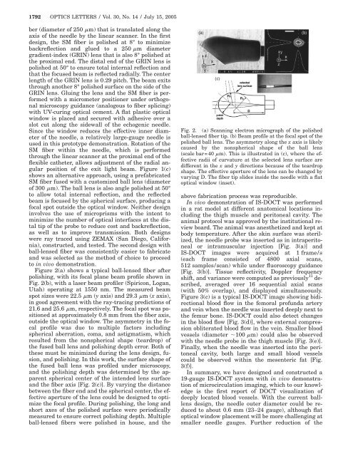
Figure 2(a) shows a typical ball-lensed fiber after<br />
polishing, with its focal plane beam pr<strong>of</strong>ile shown in<br />
Fig. 2(b), with a laser beam pr<strong>of</strong>iler (Spiricon, Logan,<br />
Utah) operating at 1550 nm. The measured beam<br />
spot sizes were 22.5 m (y axis) and 29.3 m (x axis),<br />
in good agreement with the ray-tracing predictions <strong>of</strong><br />
21.6 and 25.6 m, respectively. The focal spot was positioned<br />
at approximately 0.8 mm from the fiber axis,<br />
outside the <strong>optical</strong> window. The asymmetry in the focal<br />
pr<strong>of</strong>ile was due to multiple factors including<br />
spherical aberration, coma, and astigmatism, which<br />
resulted from the nonspherical shape (teardrop) <strong>of</strong><br />
the fused ball lens and polishing depth error. Both <strong>of</strong><br />
these must be minimized during the lens design, fusion,<br />
and polishing. In this work, the surface shape <strong>of</strong><br />
the fused ball lens was pr<strong>of</strong>iled under microscopy,<br />
and the polishing depth was determined by the apparent<br />
spherical center <strong>of</strong> the intended lens surface<br />
and the fiber axis [Fig. 2(c)]. By varying the distance<br />
between the fiber end and the spherical center, the effective<br />
aperture <strong>of</strong> the lens could be designed to optimize<br />
the focal pr<strong>of</strong>ile. During polishing, the long and<br />
short axes <strong>of</strong> the polished surface were periodically<br />
measured to ensure correct polishing depth. Multiple<br />
ball-lensed fibers were polished in house, and the<br />
Fig. 2. (a) Scanning electron micrograph <strong>of</strong> the polished<br />
ball-lensed fiber tip. (b) Beam pr<strong>of</strong>ile at the focal spot <strong>of</strong> the<br />
polished ball lens. The asymmetry along the x axis is likely<br />
caused by the nonspherical shape <strong>of</strong> the ball lens<br />
scale bar=40 m. This is illustrated in (c), where the effective<br />
radii <strong>of</strong> curvature at the selected lens surface are<br />
different in the x and y directions because <strong>of</strong> the teardrop<br />
shape. The effective aperture <strong>of</strong> the lens can be changed by<br />
varying D. The fiber tip slides inside the needle with a flat<br />
<strong>optical</strong> window (inset).<br />
above fabrication process was reproducible.<br />
In vivo demonstration <strong>of</strong> IS-DOCT was performed<br />
in a rat model at different anatomical locations including<br />
the thigh muscle and peritoneal cavity. The<br />
animal protocol was approved by the institutional review<br />
board. The animal was anesthetized and kept at<br />
body temperature. After the skin surface was sterilized,<br />
the needle probe was inserted as in intraperitoneal<br />
or intramuscular injection [Fig. 3(a)] and<br />
IS-DOCT images were acquired at 1 frame/s<br />
(each frame consisted <strong>of</strong> 4800 axial scans,<br />
512 samples/scan) while under fluoroscopy guidance<br />
[Fig. 3(b)]. Tissue reflectivity, <strong>Doppler</strong> frequency<br />
shift, and variance were computed as previously 11 described,<br />
averaged over 16 sequential axial scans<br />
(with 50% overlap), and displayed simultaneously.<br />
Figure 3(c) is a typical IS-DOCT image showing bidirectional<br />
blood flow in the femoral pr<strong>of</strong>unda artery<br />
and vein when the needle was inserted deeply next to<br />
the femur bone. IS-DOCT could also detect changes<br />
in the blood flow [Fig. 3(d)], where external compression<br />
obliterated blood flow in the vein. Smaller blood<br />
vessels (diameter 100 m) could also be observed<br />
with the needle probe in the thigh muscle [Fig. 3(e)].<br />
Finally, when the needle was inserted into the peritoneal<br />
cavity, both large and small blood vessels<br />
could be observed within the mesenteric fat [Fig.<br />
3(f)].<br />
In summary, we have designed and constructed a<br />
19-gauge IS-DOCT system with in vivo demonstration<br />
<strong>of</strong> microcirculation imaging, which to our knowledge<br />
is the first report <strong>of</strong> DOCT visualization <strong>of</strong><br />
deeply located blood vessels. With the current balllens<br />
design, the needle outer diameter could be reduced<br />
to about 0.6 mm (23–24 gauge), although flat<br />
<strong>optical</strong> window placement will be more challenging at<br />
smaller needle gauges. Further reduction <strong>of</strong> the