Interstitial Doppler optical coherence tomography - University of ...
Interstitial Doppler optical coherence tomography - University of ...
Interstitial Doppler optical coherence tomography - University of ...

Create successful ePaper yourself
Turn your PDF publications into a flip-book with our unique Google optimized e-Paper software.
July 15, 2005 / Vol. 30, No. 14 / OPTICS LETTERS 1791<br />
<strong>Interstitial</strong> <strong>Doppler</strong> <strong>optical</strong> <strong>coherence</strong> <strong>tomography</strong><br />
Victor X. D. Yang, You X. Mao, Nigel Munce, Beau Standish, and Walter Kucharczyk<br />
<strong>University</strong> Health Network, Toronto, Ontario, Canada<br />
Norman E. Marcon<br />
St. Michael’s Hospital, Toronto, Ontario, Canada<br />
Brian C. Wilson and I. Alex Vitkin<br />
Department <strong>of</strong> Medical Biophysics, <strong>University</strong> <strong>of</strong> Toronto, Toronto, Ontario, Canada<br />
Received December 20, 2004<br />
<strong>Doppler</strong> <strong>optical</strong> <strong>coherence</strong> <strong>tomography</strong> (OCT) can image tissue structure and blood flow at micrometer-scale<br />
resolution but has limited imaging depth. We report a novel, linear-scanning, needle-based <strong>Doppler</strong> OCT<br />
system using angle-polished gradient-index or ball-lensed fibers. A prototype system with a 19-guage (diameter<br />
<strong>of</strong> 0.9 mm) echogenic needle is constructed and demonstrates in vivo imaging <strong>of</strong> bidirectional blood<br />
flow in rat leg and abdominal cavity. To our knowledge, this is the first demonstration <strong>of</strong> <strong>Doppler</strong> OCT<br />
through a needle probe in interstitial applications to visualize deeply situated microcirculation. © 2005 Optical<br />
Society <strong>of</strong> America<br />
OCIS codes: 170.4500, 170.3880, 170.3340, 170.4580, 170.3890, 170.6930.<br />
Important biological research and clinical applications,<br />
such as detection <strong>of</strong> angiogenesis in embryological<br />
development and neoplastic transformation,<br />
monitoring <strong>of</strong> antiangiogenic therapy, and assessment<br />
<strong>of</strong> viability <strong>of</strong> transplanted organs, can benefit<br />
from high-resolution imaging <strong>of</strong> the microvasculature.<br />
Optical <strong>coherence</strong> <strong>tomography</strong> 1 (OCT) and its<br />
<strong>Doppler</strong> extensions 2,3 are being established as useful<br />
tools for visualizing tissue microstructure and microvasculature<br />
at resolutions close to cellular level,<br />
with velocity sensitivities approaching a few micrometers<br />
per second. 4–6 A key drawback <strong>of</strong> OCT is its<br />
limited imaging depth, typically 2–3 mm in most <strong>optical</strong>ly<br />
nontransparent tissues. <strong>Doppler</strong> OCT (DOCT)<br />
systems suffer from similar limitations, and, because<br />
<strong>of</strong> the increased signal-to-noise ratio requirement 5<br />
for accurate velocity estimation, blood flow can rarely<br />
be detected beyond 1–2 mm from the tissue surface<br />
without a priori velocity pr<strong>of</strong>ile information and extrapolation.<br />
As a result, in vivo DOCT imaging <strong>of</strong> human<br />
microvasculature has been restricted to a few<br />
transparent or superficial organ sites, such as the<br />
retina, 6,7 skin, 8–10 and mucosal layers <strong>of</strong> the gastrointestinal<br />
tract, 11,12 regardless <strong>of</strong> whether time- or<br />
spectral-domain OCT techniques were employed. Although<br />
the microstructure <strong>of</strong> deeper solid organs<br />
could be accessed by needle-based OCT, as demonstrated<br />
by Li et al. 13 with a radial sector-scanning<br />
probe, deeper microvasculature has remained out <strong>of</strong><br />
reach with existing DOCT techniques.<br />
In this Letter we describe a linear-scanning interstitial<br />
DOCT (IS-DOCT) needle probe that allows simultaneous<br />
visualization <strong>of</strong> tissue microstructure<br />
and microvasculature. The IS-DOCT needle is compatible<br />
with interventional radiological guidance by<br />
ultrasound (US) or computed <strong>tomography</strong> (CT) imaging.<br />
A prototype IS-DOCT needle with 0.9 mm diameter<br />
is constructed and demonstrates in vivo imaging<br />
<strong>of</strong> bidirectional blood flow in an animal model.<br />
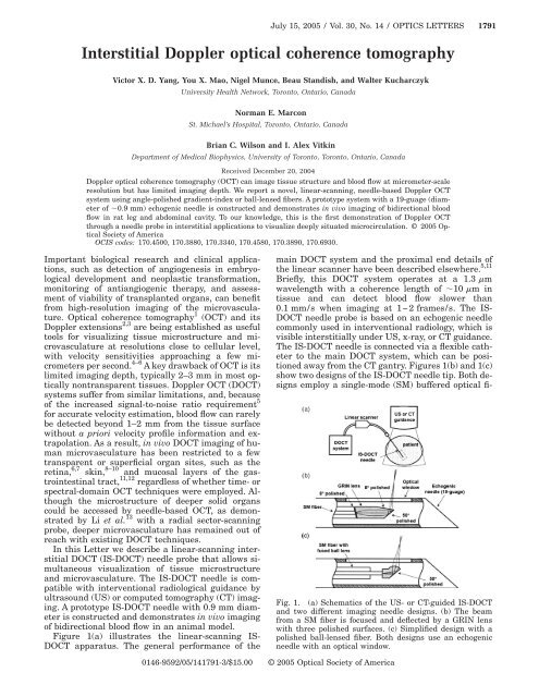
Figure 1(a) illustrates the linear-scanning IS-<br />
DOCT apparatus. The general performance <strong>of</strong> the<br />
main DOCT system and the proximal end details <strong>of</strong><br />
the linear scanner have been described elsewhere. 5,11<br />
Briefly, this DOCT system operates at a 1.3 m<br />
wavelength with a <strong>coherence</strong> length <strong>of</strong> 10 m in<br />
tissue and can detect blood flow slower than<br />
0.1 mm/s when imaging at 1−2 frames/s. The IS-<br />
DOCT needle probe is based on an echogenic needle<br />
commonly used in interventional radiology, which is<br />
visible interstitially under US, x-ray, or CT guidance.<br />
The IS-DOCT needle is connected via a flexible catheter<br />
to the main DOCT system, which can be positioned<br />
away from the CT gantry. Figures 1(b) and 1(c)<br />
show two designs <strong>of</strong> the IS-DOCT needle tip. Both designs<br />
employ a single-mode (SM) buffered <strong>optical</strong> fi-<br />
Fig. 1. (a) Schematics <strong>of</strong> the US- or CT-guided IS-DOCT<br />
and two different imaging needle designs. (b) The beam<br />
from a SM fiber is focused and deflected by a GRIN lens<br />
with three polished surfaces. (c) Simplified design with a<br />
polished ball-lensed fiber. Both designs use an echogenic<br />
needle with an <strong>optical</strong> window.<br />
0146-9592/05/141791-3/$15.00 © 2005 Optical Society <strong>of</strong> America
1792 OPTICS LETTERS / Vol. 30, No. 14 / July 15, 2005<br />
ber (diameter <strong>of</strong> 250 m) that is translated along the<br />
axis <strong>of</strong> the needle by the linear scanner. In the first<br />
design, the SM fiber is polished at 8° to minimize<br />
backreflection and glued to a 250 m diameter<br />
gradient-index (GRIN) lens that is also 8° polished at<br />
the proximal end. The distal end <strong>of</strong> the GRIN lens is<br />
polished at 50° to ensure total internal reflection and<br />
that the focused beam is reflected radially. The center<br />
length <strong>of</strong> the GRIN lens is 0.29 pitch. The beam exits<br />
through another 8° polished surface on the side <strong>of</strong> the<br />
GRIN lens. Gluing the lens and the SM fiber is performed<br />
with a micrometer positioner under orthogonal<br />
microscopy guidance (analogous to fiber splicing)<br />
with UV-curing <strong>optical</strong> cement. A flat plastic <strong>optical</strong><br />
window is placed and secured with adhesive over a<br />
slot cut along the sidewall <strong>of</strong> the echogenic needle.<br />
Since the window reduces the effective inner diameter<br />
<strong>of</strong> the needle, a relatively large-gauge needle is<br />
used in this prototype demonstration. Rotation <strong>of</strong> the<br />
SM fiber within the needle, which is performed<br />
through the linear scanner at the proximal end <strong>of</strong> the<br />
flexible catheter, allows adjustment <strong>of</strong> the radial angular<br />
position <strong>of</strong> the exit light beam. Figure 1(c)<br />
shows an alternative approach, using a prefabricated<br />
SM fiber fused with a customized ball lens (diameter<br />
<strong>of</strong> 300 m). The ball lens is also angle polished at 50°<br />
to allow total internal reflection, and the reflected<br />
beam is focused by the spherical surface, producing a<br />
focal spot outside the <strong>optical</strong> window. Neither design<br />
involves the use <strong>of</strong> microprisms with the intent to<br />
minimize the number <strong>of</strong> <strong>optical</strong> interfaces at the distal<br />
tip <strong>of</strong> the probe to reduce cost and backreflection,<br />
as well as to improve transmission. Both designs<br />
were ray traced using ZEMAX (San Diego, California),<br />
constructed, and tested. The second design with<br />
ball-lensed fiber was consistently easier to fabricate<br />
and was selected as the method <strong>of</strong> choice to proceed<br />
to in vivo demonstration.<br />
Figure 2(a) shows a typical ball-lensed fiber after<br />
polishing, with its focal plane beam pr<strong>of</strong>ile shown in<br />
Fig. 2(b), with a laser beam pr<strong>of</strong>iler (Spiricon, Logan,<br />
Utah) operating at 1550 nm. The measured beam<br />
spot sizes were 22.5 m (y axis) and 29.3 m (x axis),<br />
in good agreement with the ray-tracing predictions <strong>of</strong><br />
21.6 and 25.6 m, respectively. The focal spot was positioned<br />
at approximately 0.8 mm from the fiber axis,<br />
outside the <strong>optical</strong> window. The asymmetry in the focal<br />
pr<strong>of</strong>ile was due to multiple factors including<br />
spherical aberration, coma, and astigmatism, which<br />
resulted from the nonspherical shape (teardrop) <strong>of</strong><br />
the fused ball lens and polishing depth error. Both <strong>of</strong><br />
these must be minimized during the lens design, fusion,<br />
and polishing. In this work, the surface shape <strong>of</strong><br />
the fused ball lens was pr<strong>of</strong>iled under microscopy,<br />
and the polishing depth was determined by the apparent<br />
spherical center <strong>of</strong> the intended lens surface<br />
and the fiber axis [Fig. 2(c)]. By varying the distance<br />
between the fiber end and the spherical center, the effective<br />
aperture <strong>of</strong> the lens could be designed to optimize<br />
the focal pr<strong>of</strong>ile. During polishing, the long and<br />
short axes <strong>of</strong> the polished surface were periodically<br />
measured to ensure correct polishing depth. Multiple<br />
ball-lensed fibers were polished in house, and the<br />
Fig. 2. (a) Scanning electron micrograph <strong>of</strong> the polished<br />
ball-lensed fiber tip. (b) Beam pr<strong>of</strong>ile at the focal spot <strong>of</strong> the<br />
polished ball lens. The asymmetry along the x axis is likely<br />
caused by the nonspherical shape <strong>of</strong> the ball lens<br />
scale bar=40 m. This is illustrated in (c), where the effective<br />
radii <strong>of</strong> curvature at the selected lens surface are<br />
different in the x and y directions because <strong>of</strong> the teardrop<br />
shape. The effective aperture <strong>of</strong> the lens can be changed by<br />
varying D. The fiber tip slides inside the needle with a flat<br />
<strong>optical</strong> window (inset).<br />
above fabrication process was reproducible.<br />
In vivo demonstration <strong>of</strong> IS-DOCT was performed<br />
in a rat model at different anatomical locations including<br />
the thigh muscle and peritoneal cavity. The<br />
animal protocol was approved by the institutional review<br />
board. The animal was anesthetized and kept at<br />
body temperature. After the skin surface was sterilized,<br />
the needle probe was inserted as in intraperitoneal<br />
or intramuscular injection [Fig. 3(a)] and<br />
IS-DOCT images were acquired at 1 frame/s<br />
(each frame consisted <strong>of</strong> 4800 axial scans,<br />
512 samples/scan) while under fluoroscopy guidance<br />
[Fig. 3(b)]. Tissue reflectivity, <strong>Doppler</strong> frequency<br />
shift, and variance were computed as previously 11 described,<br />
averaged over 16 sequential axial scans<br />
(with 50% overlap), and displayed simultaneously.<br />
Figure 3(c) is a typical IS-DOCT image showing bidirectional<br />
blood flow in the femoral pr<strong>of</strong>unda artery<br />
and vein when the needle was inserted deeply next to<br />
the femur bone. IS-DOCT could also detect changes<br />
in the blood flow [Fig. 3(d)], where external compression<br />
obliterated blood flow in the vein. Smaller blood<br />
vessels (diameter 100 m) could also be observed<br />
with the needle probe in the thigh muscle [Fig. 3(e)].<br />
Finally, when the needle was inserted into the peritoneal<br />
cavity, both large and small blood vessels<br />
could be observed within the mesenteric fat [Fig.<br />
3(f)].<br />
In summary, we have designed and constructed a<br />
19-gauge IS-DOCT system with in vivo demonstration<br />
<strong>of</strong> microcirculation imaging, which to our knowledge<br />
is the first report <strong>of</strong> DOCT visualization <strong>of</strong><br />
deeply located blood vessels. With the current balllens<br />
design, the needle outer diameter could be reduced<br />
to about 0.6 mm (23–24 gauge), although flat<br />
<strong>optical</strong> window placement will be more challenging at<br />
smaller needle gauges. Further reduction <strong>of</strong> the
July 15, 2005 / Vol. 30, No. 14 / OPTICS LETTERS 1793<br />
Fig. 3. In vivo demonstration <strong>of</strong> IS-DOCT: (a) Needle<br />
probe inserted in the thigh <strong>of</strong> an anesthetized rat. (b) Fluoroscopy<br />
showing the needle position (arrow) with relation<br />
to the femur (F) and knee joint (KJ). Another needle tip * <br />
marks the surface <strong>of</strong> the skin, showing that the needle is<br />
15 mm into the tissue scale bar=10 mm. (c) IS-DOCT<br />
image <strong>of</strong> an artery–vein pair, likely the femoral pr<strong>of</strong>unda <strong>of</strong><br />
the rat. The flow velocity in the artery is higher, as shown<br />
by the aliasing effect. (d) Venous flow could be obliterated<br />
by compressing the vessel. (e) Smaller blood vessels (arrows,<br />
diameter <strong>of</strong> 100 m) were detected in the rat gluteal<br />
muscle. (f) In rat abdomen, both small and large blood<br />
vessels were detected. Because <strong>of</strong> the large velocity differences<br />
in these vessels, the larger vessels are shown with a<br />
velocity variance color scale, and the smaller vessels are<br />
shown with a <strong>Doppler</strong> shift color scale (green window). The<br />
imaging depth was reduced beneath large blood vessels,<br />
likely due to blood attenuation <strong>of</strong> the signal. The IS-DOCT<br />
image dimensions are 2.5 mm1.5 mm.<br />
needle size is desirable with a smaller ball lens and<br />
custom-designed <strong>optical</strong> windows to minimize<br />
trauma to the tissue. Compared with a previous<br />
semispherical microlens design, 14 the current design<br />
allowed aperture change independent <strong>of</strong> ball-lens radius,<br />
which facilitated focus optimization. Whereas<br />
the current needle material is compatible with US,<br />
CT, or x-ray guidance, magnet-safe material can be<br />
used to fabricate an IS-DOCT probe for use with a<br />
magnetic resonance imager. Long flexible needles, inserted<br />
through the instrument channels <strong>of</strong> an endoscope,<br />
can also be used to image peri-intestinal structures<br />
under endoscopic ultrasound guidance. These<br />
different implementations will greatly expand the<br />
anatomical sites accessible to the high spatial resolution<br />
and flow velocity sensitivity <strong>of</strong> DOCT, making in<br />
vivo microstructural and microvascular visualization<br />
<strong>of</strong> deep tissues a possibility in the brain, liver, pancreas,<br />
kidneys, lungs, lymph nodes, breasts, or prostate.<br />
IS-DOCT may have clinical applications in providing<br />
microvascular assessment for diagnostic use<br />
or therapeutic monitoring <strong>of</strong> neoplastic diseases. For<br />
basic research, IS-DOCT may be used for imaging<br />
early cardiogenesis in small in utero embryos, such<br />
as mice or rats.<br />
This work was supported by the Natural Science<br />
and Engineering Research Council <strong>of</strong> Canada, Canadian<br />
Institutes for Health Research, Canadian Foundation<br />
for Innovation, Photonics Research Ontario,<br />
Canadian Cancer Society, National Cancer Institute<br />
<strong>of</strong> Canada, and the Gordon Lang Foundation. We are<br />
grateful to the reviewers for notifying us during the<br />
submission <strong>of</strong> this Letter <strong>of</strong> a previous polished balllens<br />
demonstration. 15 We thank T. Liu, M. Sinclair, J.<br />
Li, and P. Herman for experimental assistance. V. X.<br />
D. Yang (victor.yang@utoronto.ca) thanks F. S. Foster,<br />
L. M. Wongkeesong, C. S. Ho, and K. Bukhanov<br />
for inspiring discussions.<br />
References<br />
1. D. Huang, E. A. Swanson, C. P. Lin, J. S. Schuman, W.<br />
G. Stinson, W. Chang, M. R. Hee, T. Flotte, K. Gregory,<br />
C. A. Puliafito, and J. G. Fujimoto, Science 254, 1178<br />
(1991).<br />
2. Z. P. Chen, T. E. Milner, D. Dave, and J. S. Nelson,<br />
Opt. Lett. 22, 64 (1997).<br />
3. J. A. Izatt, M. D. Kulkarni, S. Yazdanfar, J. K. Barton,<br />
and A. J. Welch, Opt. Lett. 22, 1439 (1997).<br />
4. S. Yazdanfar, A. M. Rollins, and J. A. Izatt, Proc. SPIE<br />
4251, 156 (2001).<br />
5. V. X. D. Yang, M. L. Gordon, B. Qi, J. Pekar, S. Lo, E.<br />
Seng-Yue, A. Mok, B. C. Wilson, and I. A. Vitkin, Opt.<br />
Express 11, 794 (2003).<br />
6. B. R. White, M. C. Pierce, N. Nassif, B. Cense, B. H.<br />
Park, G. J. Tearney, B. E. Bouma, T. C. Chen, and J. F.<br />
de Boer, Opt. Express 11, 3490 (2003).<br />
7. S. Yazdanfar, A. M. Rollins, and J. A. Izatt, Opt. Lett.<br />
25, 1448 (2000).<br />
8. Y. H. Zhao, Z. P. Chen, C. Saxer, S. H. Xiang, J. F. de<br />
Boer, and J. S. Nelson, Opt. Lett. 25, 114 (2000).<br />
9. S. Tang, M. L. Gordon, V. X. D. Yang, M. E. Faughnan,<br />
M. Cirocco, B. Qi, E. Seng-Yue, G. Gardiner, G. B.<br />
Haber, G. Kandel, P. Kortan, I. A. Vitkin, B. C. Wilson,<br />
and N. E. Marcon, Gastrointest. Endosc. 58, 591<br />
(2003).<br />
10. Y. Zhao, Z. P. Chen, C. Saxer, Q. Shen, S. Xiang, J. F.<br />
de Boer, and J. S. Nelson, Opt. Lett. 25, 1358 (2000).<br />
11. V. X. D. Yang, M. L. Gordon, S. Tang, N. E. Marcon, G.<br />
Gardiner, B. Qi, S. Bisland, E. Seng-Yue, S. Lo, J.<br />
Pekar, A. Mok, B. C. Wilson, and I. A. Vitkin, Opt.<br />
Express 11, 2416 (2003).<br />
12. V. X. D. Yang, S. Tang, M. L. Gordon, B. Qi, G.<br />
Gardiner, M. Cirocco, P. Kortan, G. Haber, G. Kandel,<br />
I. A. Vitkin, and B. C. Wilson, “Endoscopic <strong>Doppler</strong><br />
<strong>optical</strong> <strong>coherence</strong> <strong>tomography</strong> in human<br />
gastrointestinal tract: initial experience,” Gastrointest.<br />
Endosc. (to be published).<br />
13. X. Li, C. Chudoba, T. Ko, C. Pitris, and J. G. Fujimoto,<br />
Opt. Lett. 25, 1520 (2000).<br />
14. S. A. Boppart, W. Luo, D. L. Marks, and<br />
K. W. Singletary, Breast Cancer Res. Treat. 84,<br />
85 (2004).<br />
15. M. Shishkov, G. J. Tearney, and B. E. Bouma, OSA<br />
Biomedical Topical Meeting (Optical Society <strong>of</strong> America<br />
2004), paper SE5.