Focal Length of Lenses - Ryerson Department of Physics
Focal Length of Lenses - Ryerson Department of Physics
Focal Length of Lenses - Ryerson Department of Physics

Create successful ePaper yourself
Turn your PDF publications into a flip-book with our unique Google optimized e-Paper software.
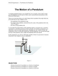
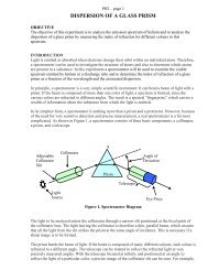
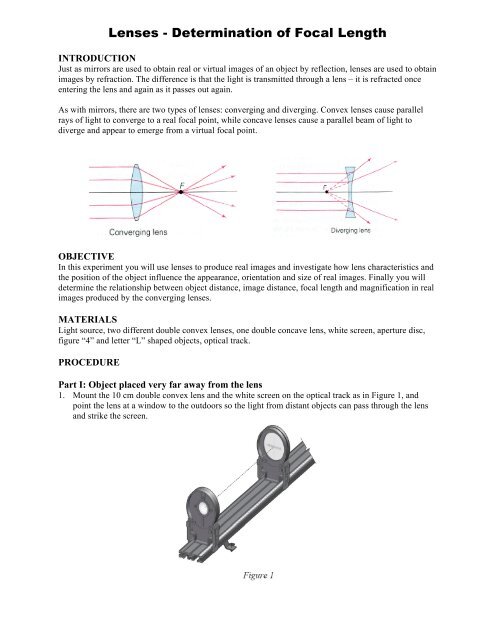
<strong>Lenses</strong> - Determination <strong>of</strong> <strong>Focal</strong> <strong>Length</strong>INTRODUCTIONJust as mirrors are used to obtain real or virtual images <strong>of</strong> an object by reflection, lenses are used to obtainimages by refraction. The difference is that the light is transmitted through a lens – it is refracted onceentering the lens and again as it passes out again.As with mirrors, there are two types <strong>of</strong> lenses: converging and diverging. Convex lenses cause parallelrays <strong>of</strong> light to converge to a real focal point, while concave lenses cause a parallel beam <strong>of</strong> light todiverge and appear to emerge from a virtual focal point.OBJECTIVEIn this experiment you will use lenses to produce real images and investigate how lens characteristics andthe position <strong>of</strong> the object influence the appearance, orientation and size <strong>of</strong> real images. Finally you willdetermine the relationship between object distance, image distance, focal length and magnification in realimages produced by the converging lenses.MATERIALSLight source, two different double convex lenses, one double concave lens, white screen, aperture disc,figure “4” and letter “L” shaped objects, optical track.PROCEDUREPart I: Object placed very far away from the lens1. Mount the 10 cm double convex lens and the white screen on the optical track as in Figure 1, andpoint the lens at a window to the outdoors so the light from distant objects can pass through the lensand strike the screen.
2. Change the lens-screen distance until you obtain a sharp image <strong>of</strong> the objects seen through thewindow.3. Mount the variable aperture disc holder on the track in front <strong>of</strong> the lens toward the window andinvestigate the effect <strong>of</strong> the size and shape <strong>of</strong> the aperture on the image. Repeat your observationswith the aperture disc on the other side <strong>of</strong> the lens.4. Record in Table 1 your observations regarding the following characteristics <strong>of</strong> the image:• Position relative to the lens compared to position <strong>of</strong> the objects to the lens• Size <strong>of</strong> the image compared to the size <strong>of</strong> the objects• Orientation <strong>of</strong> the image compared to that <strong>of</strong> the objects• Nature <strong>of</strong> the image: real or virtual5. Repeat steps 1 through 4 with the 20 cm double convex lens.6. Repeat steps 1 through 4 with the -15 cm double concave lens.Table 1: Image characteristics when the object is placed very far away from the lensLens Type Image CharacteristicsPosition:10 cm Size:Double Convex Orientation:Nature:20 cmDouble Convex-15 cmDouble ConcavePosition:Size:Orientation:Nature:Position:Size:Orientation:Nature:The number (expressed in cm) on each lens holder equals the value <strong>of</strong> the focal length <strong>of</strong> that lens. Howdo the three image positions in the Table 1 compare to these three numbers?Part II: Object placed closer to the lens on the optical track1. Mount the light source, the 10 cm double convex lens and the screen on the optical track as in Figure2. Turn the light source wheel until the number “4” is visible in the opening; this will be your object.Move the lens and/or screen until you obtain a sharp real image <strong>of</strong> the object on the screen.2. Mount the variable aperture disc holder on the track on each side <strong>of</strong> the lens and investigate the effect<strong>of</strong> the size and shape <strong>of</strong> the aperture on the image in each case.
3. Measure and record in the Table 2 the following distances and heights:a. Distance from object to lens (d o )b. Distance from image to lens (d i )c. Height <strong>of</strong> the object (h o )d. Height <strong>of</strong> the image on screen (h i )4. Denoting by f the focal length <strong>of</strong> the lens, use the lens equation:and determine the value <strong>of</strong> f (cm).1f = 1 d 0+ 1 d i5. Change the distance from object to lens and repeat steps 3 and 4.6. Repeat step 5 two more times.d o (cm) d i (cm) f (cm) h o (cm) h i (cm) -h i /h o -d i /d o7. Calculate the values for the last two columns <strong>of</strong> the table. How do they compare?8. Plot the graph <strong>of</strong> 1/d i versus 1/d o and determine the focal length <strong>of</strong> the lens from the value <strong>of</strong>the intercept <strong>of</strong> the line with the y-axis.1d i1d 09. Compare the value <strong>of</strong> focal length determined from this graph with the value estimated inPart I in Table 1.