EvEry bEaring you nEEd
EvEry bEaring you nEEd
EvEry bEaring you nEEd

Create successful ePaper yourself
Turn your PDF publications into a flip-book with our unique Google optimized e-Paper software.
Crank pins<br />
1st order<br />
2nd order<br />
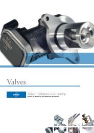
Constructing an efficient and durable bearing is not just a<br />
matter of optimally designed bearing shells. the crank pins<br />
also play a vital role, since any departure from the permissible<br />
geometry can lead to bearing damage.<br />
3rd order<br />
4th order<br />
[fig.16]<br />
Typical form errors of crankshaft journals in radial<br />
direction from the ideal round shape. The illustration<br />
shows deviations from first to sixth order. Such form<br />
errors are created when it comes to harmonic vibrations<br />
5th order<br />
6th order<br />
between the grinding wheel and the turning crankshaft.<br />
[4]<br />
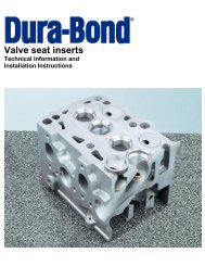
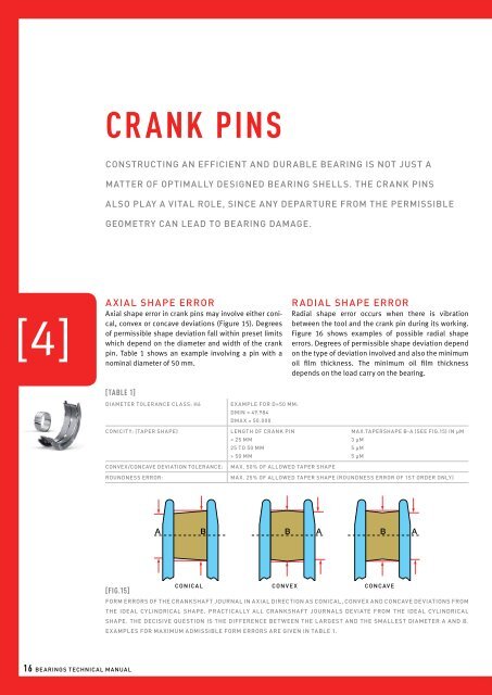
Axial shape error<br />
Axial shape error in crank pins may involve either conical,<br />
convex or concave deviations (Figure 15). Degrees<br />
of permissible shape deviation fall within preset limits<br />
which depend on the diameter and width of the crank<br />
pin. Table 1 shows an example involving a pin with a<br />
nominal diameter of 50 mm.<br />
[Table 1]<br />
DIAMETER TOLERANCE CLASS: h6<br />
CONICITY: (Taper shape)<br />
CONVEX/CONCAVE DEVIATION TOLERANCE:<br />
ROUNDNESS ERROR:<br />
[fig.15]<br />
A<br />
Example for D=50 mm:<br />
Dmin = 49.984<br />
Dmax = 50.000<br />
Length of Crank Pin<br />
< 25 mm<br />
25 to 50 mm<br />
> 50 mm<br />
Max. 50% of allowed taper shape<br />
Radial shape error<br />
Radial shape error occurs when there is vibration<br />
between the tool and the crank pin during its working.<br />
Figure 16 shows examples of possible radial shape<br />
errors. Degrees of permissible shape deviation depend<br />
on the type of deviation involved and also the minimum<br />
oil film thickness. The minimum oil film thickness<br />
depends on the load carry on the bearing.<br />
B B A<br />
B A<br />
conical convex concave<br />
Max.Tapershape b-a (see fig.15) in µm<br />
3 µm<br />
5 µm<br />
5 µm<br />
Max. 25% of allowed taper shape (Roundness Error of 1st Order only)<br />
Form errors of the crankshaft journal in axial direction as conical, convex and concave deviations from<br />
the ideal cylindrical shape. Practically all crankshaft journals deviate from the ideal cylindrical<br />
shape. the decisive question is the difference between the largest and the smallest diameter a and b.<br />
Examples for maximum admissible form errors are given in table 1.<br />
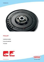
Surface roughness<br />
Alongside axial and radial shape errors, surface quality is a<br />
further important property of a crank pin. High surface quality<br />
leads to minimal wear to the pin and its bearing. Table 2 shows<br />
some guidelines for surface roughness parameters Ra and Rz.<br />
[Table 2]<br />
N<br />
a) HEAVY LOAD BEARINGS (especially diesel engines) (> 45 ) MM 2<br />
Ra<br />
Rz<br />
Max. 0.2 µm<br />
Max. 0.8 µm<br />
N<br />
MM 2<br />
Max. 0.4 µm<br />
Max. 1.5 µM<br />
B) STANDARD LOAD BEARINGS (< 45 )<br />
Ra<br />
Rz<br />
NCI crankshafts<br />
Today crankshafts are manufactured either of steel or nodular<br />
cast iron (NCI). NCI contains graphite inclusions (so-called<br />
graphite nodules) which improve the material’s elasticity. When<br />
working NCI pins one special characteristic must be taken into<br />
account.<br />
When a nodular cast iron pin is reground <strong>you</strong> will cut into the<br />
graphite inserts, and ‘smearing’ of the material during the cutting<br />
process leads to the formation of ‘lids’ which cover the graphite<br />
inserts. Thus, although the surface has a smooth external<br />
appearance, stresses on the lids while the engine is running can<br />
cause them to break off, leading to bearing damage (see Figures<br />
17 & 18). The formation of lids must be avoided at all costs.<br />
This can be done in two ways. Firstly, the formation of lids can<br />
be minimised by the use of CBN (cubic crystalline boron nitride)<br />
strips. Secondly, after grinding the shaft can be gas nitrated and<br />
polished. Gas nitrated lids are more brittle and snap off more<br />
readily during polishing. It should be noted that grinding and<br />
polishing should be done in opposing directions, with polishing<br />
taking place in the engine’s direction of rotation.<br />
surface of<br />
crankshaft<br />
journal<br />
‘lid’<br />
graphite<br />
inclusions<br />
[fig.17] surface of crankshaft ‘lid’ graphite<br />
inclusions<br />
Sketch of a magnified cross sec-tional view of a crankshaft<br />
journal made of nodular graphite iron. the<br />
hatched areas represent inclusions of graphite in<br />
the iron matrice. graphite inclusions are cut when<br />
the crankshaft journal is regrinded. The cutting tool<br />
smears iron over the inclusion so that the inclusion is<br />
covered partially or totally by a lid. Such lids can be<br />
dangerous for the engine. The cyclic load on the bearing<br />
can make the lids vibrate and break. If the lids break,<br />
they can damage the bearing as dirt particles.<br />
[fig.18]<br />
300 times magnified view of the surface of a crankshaft<br />
journal made of nodular graphite iron after grinding.<br />
One can clearly see the lids explained in figure 17.<br />
16 Bearings Technical Manual<br />
17