GV-IO Box 8 Ports - GeoVision
GV-IO Box 8 Ports - GeoVision
GV-IO Box 8 Ports - GeoVision

Create successful ePaper yourself
Turn your PDF publications into a flip-book with our unique Google optimized e-Paper software.
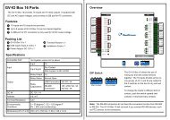
<strong>GV</strong>-<strong>IO</strong> <strong>Box</strong> 8 <strong>Ports</strong><br />
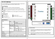
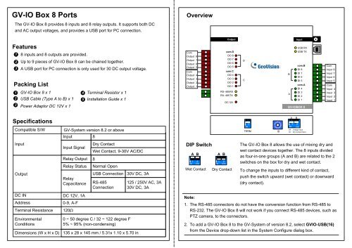
Overview<br />
The <strong>GV</strong>-<strong>IO</strong> <strong>Box</strong> 8 provides 8 inputs and 8 relay outputs. It supports both DC<br />
and AC output voltages, and provides a USB port for PC connection.<br />
Output<br />
Input<br />
Features<br />
1<br />
2<br />
3<br />
Packing List<br />
1<br />
2<br />
3<br />
8 inputs and 8 outputs are provided.<br />
Up to 9 pieces of <strong>GV</strong>-<strong>IO</strong> <strong>Box</strong> 8 can be chained together.<br />
A USB port for PC connection is only used for 30 DC output voltage.<br />
<strong>GV</strong>-<strong>IO</strong> <strong>Box</strong> 8 x 1<br />
4 Terminal Resistor x 1<br />
USB Cable (Type A to B) x 1 5 Installation Guide x 1<br />
Power Adaptor DC 12V x 1<br />
Com<br />
Output 8<br />
Output 7<br />
Output 6<br />
Output 5<br />
Com<br />
Output 4<br />
Output 3<br />
Output 2<br />
Output 1<br />
com.D<br />
DO 8<br />
DO 7<br />
DO 6<br />
DO 5<br />
com.C<br />
DO 4<br />
DO 3<br />
DO 2<br />
DO 1<br />
RS- 485 RX<br />
RX- 485 TX<br />
DC 12V<br />
D<br />
C<br />
USB RX<br />
USB TX<br />
com.B<br />
DI 8<br />
B<br />
DI 7<br />
DI 6<br />
DI 5<br />
com.A<br />
DI 4<br />
DI 3<br />
A<br />
DI 2<br />
DI 1<br />
<strong>GV</strong>-<strong>IO</strong>BOX 8<br />
Com<br />
Input 8<br />
Input 7<br />
Input 6<br />
Input 5<br />
Com<br />
Input 4<br />
Input 3<br />
Input 2<br />
Input 1<br />
Specifications<br />
Compatible S/W<br />
Input<br />
Output<br />
DC IN<br />
Address<br />
Terminal Resistance<br />
Environmental<br />
Conditions<br />
Dimensions (W x H x D)<br />
<strong>GV</strong>-System version 8.2 or above<br />
Input 8<br />
Input Signal<br />
Relay Output<br />
Relay Status<br />
Relay<br />
Capacitance<br />
DC 12V, 1A<br />
0-9, A-F<br />
120<br />
Dry Contact<br />
Wet Contact, 9-30V AC/DC<br />
8<br />
Normal Open<br />
USB Connection<br />
RS-485<br />
Connection<br />
0 ~ 50 degree C / 32 ~ 122 degree F<br />
5% ~ 95% (non-condensing)<br />
30V DC, 3A<br />
135 x 28 x 145 mm / 5.31x 1.10 x 5.70 in<br />
125 / 250V AC, 3A<br />
30V DC, 3A<br />
DIP Switch<br />
ON<br />
A B<br />
1 2<br />
ECE<br />
Wet Contact<br />
ON<br />
A B<br />
1 2<br />
ECE<br />
Dry Contact<br />
ON<br />
1<br />
TERM<br />
3<br />
E<br />
B<br />
ID<br />
A B<br />
1 2<br />
ON ECE<br />
Off : Voltage Input<br />
On : Dry Contact Input<br />
The <strong>GV</strong>-<strong>IO</strong> <strong>Box</strong> 8 allows the use of mixing dry and<br />
wet contact devices together. The 8 inputs divided<br />
as four-in-one groups (A and B) are related to the 2<br />
switches on the box for dry and wet contact.<br />
To change the inputs to different kind of contact,<br />
push the switch upward (wet contact) or downward<br />
(dry contact).<br />
Note:<br />
1. The RS-485 connectors do not have the conversion function from RS-485 to<br />
RS-232. The <strong>GV</strong>-<strong>IO</strong> <strong>Box</strong> 8 will not work if you connect RS-485 devices, such as<br />
PTZ camera, to the connectors.<br />
2. To add a <strong>GV</strong>-<strong>IO</strong> <strong>Box</strong> 8 to the <strong>GV</strong>-System of version 8.2, select <strong>GV</strong><strong>IO</strong>-USB(16)<br />
from the Device drop-down list in the System Configure dialog box.
Output<br />
com.D<br />
DO 8<br />
DO 7<br />
DO 6<br />
DO 5<br />
com. C<br />
DO 4<br />
DO 3<br />
DO 2<br />
DO 1<br />
RS- 485 RX<br />
RX- 485 TX<br />
DC 12V<br />
D<br />
C<br />
Output<br />
com.D<br />
DO 8<br />
DO 7<br />
DO 6<br />
DO 5<br />
com. C<br />
DO 4<br />
DO 3<br />
DO 2<br />
DO 1<br />
RS- 485 RX<br />
RX- 485 TX<br />
DC 12V<br />
D<br />
C<br />
B<br />
A<br />
Input<br />
USB RX<br />
USB TX<br />
com .B<br />
DI 8<br />
DI 7<br />
DI 6<br />
DI 5<br />
com .A<br />
DI 4<br />
DI 3<br />
DI 2<br />
DI 1<br />
B<br />
A<br />
Input<br />
USB RX<br />
USB TX<br />
com .B<br />
DI 8<br />
DI 7<br />
DI 6<br />
DI 5<br />
com .A<br />
DI 4<br />
DI 3<br />
DI 2<br />
DI 1<br />
Output<br />
com.D<br />
DO 8<br />
DO 7<br />
DO 6<br />
DO 5<br />
com. C<br />
DO 4<br />
DO 3<br />
DO 2<br />
DO 1<br />
RS- 485 RX<br />
RX- 485 TX<br />
DC 12V<br />
D<br />
C<br />
Input<br />
USB RX<br />
USB TX<br />
com .B<br />
DI 8<br />
B DI 7<br />
DI 6<br />
DI 5<br />
com .A<br />
DI 4<br />
DI 3<br />
A<br />
DI 2<br />
DI 1<br />
<strong>GV</strong>-<strong>IO</strong>BOX 8<br />
Output<br />
com.D<br />
DO 8<br />
DO 7<br />
DO 6<br />
DO 5<br />
com.C<br />
DO 4<br />
DO 3<br />
DO 2<br />
DO 1<br />
RS- 485 RX<br />
RX- 485 TX<br />
DC 12V<br />
D<br />
C<br />
B<br />
A<br />
Input<br />
USB RX<br />
USB TX<br />
com .B<br />
DI 8<br />
DI 7<br />
DI 6<br />
DI 5<br />
com .A<br />
DI 4<br />
DI 3<br />
DI 2<br />
DI 1<br />
<strong>GV</strong>-<strong>IO</strong>BOX 8<br />
Connections to PC<br />
There are two ways to connect a <strong>GV</strong>-<strong>IO</strong> <strong>Box</strong> 8 to the PC:<br />
(1) Use the USB cable to connect to the PC, and<br />
(2) Through the option of <strong>GV</strong>-Hub, <strong>GV</strong>-COM, <strong>GV</strong>-NET Card or <strong>GV</strong>-NET/<strong>IO</strong> Card,<br />
use the RS-485 connectors to connect with the PC.<br />
Assigning Addresses to <strong>GV</strong>-<strong>IO</strong> <strong>Box</strong> 8<br />
Up to 9 pieces of <strong>GV</strong>-<strong>IO</strong> <strong>Box</strong> 8 can be chained together to expand the I/O<br />
capacity. Use the ID Switch to assign addresses 1~9 to the connected pieces of<br />
<strong>GV</strong>-<strong>IO</strong> <strong>Box</strong> 8.<br />
1. Use the USB cable to connect one <strong>GV</strong>-<strong>IO</strong> <strong>Box</strong> 8 to the PC.<br />
(Allowed for DC Output Voltage only)<br />
USB cable<br />
PC<br />
<strong>GV</strong>-<strong>IO</strong>BOX 8<br />
PC<br />
<strong>GV</strong>-<strong>IO</strong> <strong>Box</strong> 8<br />
Note: It is required to install the USB driver. See USB Driver Installation later in<br />
this document.<br />
RS-485 +/- RS-485 +/-<br />
RS-485 +/-<br />
2. Use the RS-485 connectors to connect one <strong>GV</strong>-<strong>IO</strong> <strong>Box</strong> 8 with the PC.<br />
(Allowed for AC/DC Output Voltage)<br />
<strong>GV</strong>-<strong>IO</strong> <strong>Box</strong> 8 (1) <strong>GV</strong>-<strong>IO</strong> <strong>Box</strong> 8 (2) <strong>GV</strong>-<strong>IO</strong> <strong>Box</strong> 8 (9)<br />
~<br />
ID Switch<br />
1. Addresses 0 and A to F are NOT functional.<br />
PC<br />
<strong>GV</strong>-Hub / <strong>GV</strong>-COM<br />
<strong>GV</strong>-NET Card /<br />
<strong>GV</strong>-NET/<strong>IO</strong> Card<br />
RS-485+<br />
RS-485-<br />
<strong>GV</strong>-<strong>IO</strong>BOX 8<br />
<strong>GV</strong>-<strong>IO</strong> <strong>Box</strong> 8<br />
E<br />
B<br />
ID<br />
2. Assign the addresses when the power is off.<br />
3. If you want to change the assigned address of the<br />
connected <strong>GV</strong>-<strong>IO</strong> <strong>Box</strong> 8, set the switch to the new<br />
address, and then re-plug the power adaptor.
Long-Distance Connections<br />
It is required to switch on the Terminal Resistance Switches when the connection<br />
distance is longer than 200 meters (656.16 feet). Three conditions below illustrate<br />
how the Terminal Resistance Switches should be switched on.<br />
3. Multiple pieces of <strong>GV</strong>-<strong>IO</strong> <strong>Box</strong> 8 are connected with the PC through<br />
separate RS-485 cables.<br />
If you connect multiple pieces of <strong>GV</strong>-<strong>IO</strong> <strong>Box</strong> 8 with the PC through separate<br />
RS-485 cables, switch on Terminal Resistance Switches of the connected<br />
piece of <strong>GV</strong>-<strong>IO</strong> <strong>Box</strong> 8 at the end of each cable.<br />
1. Multiple pieces of <strong>GV</strong>-<strong>IO</strong> <strong>Box</strong> 8 are connected with the PC through one<br />
single RS-485 cable.<br />
If you connect multiple pieces of <strong>GV</strong>-<strong>IO</strong> <strong>Box</strong> 8 with the PC, only switch on the<br />
Terminal Resistance Switches in the first and last connected pieces of <strong>GV</strong>-<strong>IO</strong><br />
<strong>Box</strong> 8.<br />
RS-485 Cable<br />
ON<br />
RS-485 Cable 1<br />
RS-485-<br />
RS-485 Cable 2<br />
ON<br />
PC<br />
USB Cable<br />
1<br />
ON<br />
<strong>GV</strong>-<strong>IO</strong> <strong>Box</strong> 8<br />
(the first)<br />
1<br />
ON<br />
1<br />
ON<br />
<strong>GV</strong>-<strong>IO</strong> <strong>Box</strong> 8 <strong>GV</strong>-<strong>IO</strong> <strong>Box</strong> 8<br />
(the last)<br />
RS-485 Cable<br />
<strong>GV</strong>-<strong>IO</strong> <strong>Box</strong> 8<br />
(the last of Cable 1)<br />
RS-485+<br />
<strong>GV</strong>-NET/<strong>IO</strong> Card /<br />
<strong>GV</strong>-NET Card /<br />
<strong>GV</strong>-Hub / <strong>GV</strong>-COM /<br />
<strong>GV</strong>-<strong>IO</strong> <strong>Box</strong> 8<br />
(the last of Cable 2)<br />
2. Multiple pieces of <strong>GV</strong>-<strong>IO</strong> <strong>Box</strong> 8 are connected with the PC through a<br />
RS-485 / RS-232 conversion device.<br />
If you connect multiple pieces of <strong>GV</strong>-<strong>IO</strong> <strong>Box</strong> 8 with the PC through a RS-485 /<br />
RS-232 conversion device, such as <strong>GV</strong>-NET/<strong>IO</strong> Card and <strong>GV</strong>-Hub, insert a<br />
Terminal Resistor in the conversion device and switch on the Terminal<br />
Resistance Switch of the last connected <strong>GV</strong>-<strong>IO</strong> <strong>Box</strong> 8.<br />
Terminal Resistance Switch<br />
1<br />
ON<br />
To switch on the Terminal Resistance Switch, push<br />
the switch downward.<br />
PC<br />
RS-485 Cable<br />
RS-485-<br />
Terminal Resistor<br />
ON<br />
ON<br />
RS-485+<br />
<strong>GV</strong>-NET/<strong>IO</strong> Card /<br />
<strong>GV</strong>-NET Card /<br />
<strong>GV</strong>-Hub / <strong>GV</strong>-COM<br />
RS-485 Cable<br />
<strong>GV</strong>-<strong>IO</strong> <strong>Box</strong> 8<br />
<strong>GV</strong>-<strong>IO</strong> <strong>Box</strong> 8<br />
(the last)
USB Driver Installation<br />
To use the USB function, it is required to install the driver on the PC. Follow<br />
these steps to install the driver:<br />
1. Insert the software DVD. It will run automatically and pop up a window.<br />
2. Select Install or Remove <strong>GeoVision</strong> <strong>GV</strong>-Series Driver, and then click<br />
Install <strong>GeoVision</strong> USB Device Drivers. This dialog box appears.<br />
3. Click Install to install the drivers. When the installation is complete, this<br />
message will appear: Install done!<br />
4. Click Exit to close the dialog box.<br />
5. To verify the drivers are installed correctly, go to Device Manager. Expanding<br />
the <strong>Ports</strong> field, you should see one entry for Prolific USB-to-Serial Bridge.<br />
2009.5.27