GV-LPR License Plate Recognition User Manual - GeoVision
GV-LPR License Plate Recognition User Manual - GeoVision
GV-LPR License Plate Recognition User Manual - GeoVision

You also want an ePaper? Increase the reach of your titles
YUMPU automatically turns print PDFs into web optimized ePapers that Google loves.
<strong>GV</strong>-<strong>LPR</strong><br />
<strong>License</strong> <strong>Plate</strong> <strong>Recognition</strong><br />
<strong>User</strong> <strong>Manual</strong><br />
V3.0
© 2008 <strong>GeoVision</strong>, Inc. All rights reserved.<br />
Under the copyright laws, this manual may not be copied, in whole or in part,<br />
without the written consent of <strong>GeoVision</strong>.<br />
Every effort has been made to ensure that the information in this manual is<br />
accurate. <strong>GeoVision</strong> is not responsible for printing or clerical errors.<br />
<strong>GeoVision</strong>, Inc.<br />
9F, No. 246, Sec. 1, Neihu Rd.,<br />
Neihu District, Taipei, Taiwan<br />
Tel: +886-2-8797-8377<br />
Fax: +886-2-8797-8335<br />
http://www.geovision.com.tw<br />
Trademarks used in this manual: <strong>GeoVision</strong>, the <strong>GeoVision</strong> logo and <strong>GV</strong><br />
series products are trademarks of <strong>GeoVision</strong>, Inc. Windows and Windows XP<br />
are registered trademarks of Microsoft Corporation.<br />
May 2008
Contents<br />
1. Hardware Installation........................................................ 1<br />
1.1 Install Video Capture Card..................................................................... 1<br />
1.1.1 Connections of Video Captured Card....................................... 2<br />
1.1.2 Install Driver ............................................................................. 3<br />
1.1.3 Connect Hardware Watchdog .................................................. 3<br />
1.2 Install Dongle ......................................................................................... 4<br />
1.2.1 With a <strong>GV</strong> Video Capture Card on <strong>GV</strong>-<strong>LPR</strong> System .................. 4<br />
1.2.2 Without a <strong>GV</strong> Video Capture Card on <strong>GV</strong>-<strong>LPR</strong> System ........... 4<br />
1.2.3 Install Driver ............................................................................... 4<br />
1.3 Install I/O Module ................................................................................... 6<br />
1.3.1 Install <strong>GV</strong>-NET Card V3.1 ........................................................ 7<br />
1.3.2 Install <strong>GV</strong>-NET I/O Card V3.1................................................... 8<br />
1.3.3 Install <strong>GV</strong>-COM ........................................................................ 9<br />
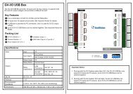
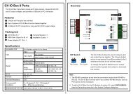
1.3.4 Install <strong>GV</strong>-I/O USB Box .......................................................... 10<br />
2. Software Installation ....................................................... 11<br />
2.1 Install <strong>GV</strong>-<strong>LPR</strong> Application................................................................... 11<br />
2.2 Install Microsoft Data Access Components (MDAC)............................ 14<br />
2.2.1 Check the version of MDAC ................................................... 14<br />
2.2.2 Install MDAC .......................................................................... 16<br />
2.3 Run <strong>GV</strong>-<strong>LPR</strong> ........................................................................................ 17<br />
2.4 Uninstall <strong>GV</strong>-<strong>LPR</strong> Application .............................................................. 18<br />
3. System Configuration..................................................... 19<br />
3.1 Main Screen Features.......................................................................... 19<br />
3.2 System Configure ................................................................................ 22<br />
3.2.1 System Configuration ............................................................. 22<br />
3.2.1.1 General Setting .......................................................... 23<br />
3.2.1.2 Camera 1 ~ 8.............................................................. 27<br />
i
3.2.1.3 I/O Device................................................................... 32<br />
3.2.2 Integration Setup .................................................................... 37<br />
3.2.3 Export Setting......................................................................... 38<br />
3.2.4 Counter Setting ...................................................................... 43<br />
3.2.5 Repeat <strong>Recognition</strong> Setting.................................................... 44<br />
3.2.6 Country Setting....................................................................... 45<br />
3.2.7 Alarm Definition Setting.......................................................... 45<br />
3.2.8 E-Mail Setting ......................................................................... 48<br />
3.2.9 Virtual I/O Setting ................................................................... 48<br />
3.2.10 Remote DVR Player Setting................................................... 49<br />
3.2.11 Registered <strong>Plate</strong>s Database................................................... 49<br />
3.2.12 Speed Setting......................................................................... 54<br />
3.2.13 Video Source.......................................................................... 54<br />
3.3 Start / Stop <strong>Recognition</strong> ....................................................................... 55<br />
3.4 Version / Minimize / Exit....................................................................... 55<br />
4. <strong>Recognition</strong> Database .................................................... 56<br />
4.1 <strong>Recognition</strong> Records............................................................................ 56<br />
4.2 <strong>Recognition</strong> Database.......................................................................... 57<br />
4.2.1 Query...................................................................................... 58<br />
4.2.2 Export <strong>Recognition</strong> Records................................................... 59<br />
4.2.3 View <strong>Recognition</strong> Video.......................................................... 59<br />
4.2.4 View Overview Video.............................................................. 60<br />
4.3 Watermark Proof.................................................................................. 60<br />
5. Registered <strong>Plate</strong>s Database ........................................... 63<br />
5.1 Add Record .......................................................................................... 64<br />
5.2 Edit Record .......................................................................................... 65<br />
5.3 Delete Record ...................................................................................... 65<br />
5.4 Perform Record Queries ...................................................................... 65<br />
5.5 Go to Record........................................................................................ 65<br />
5.6 Print ..................................................................................................... 65<br />
5.7 Preview ................................................................................................ 66<br />
5.8 Display Extra Data ............................................................................... 66<br />
ii
5.9 Select Type of Data for Display............................................................ 66<br />
6. Notifications .................................................................... 67<br />
6.1 I/O Notifications.................................................................................... 67<br />
6.2 Hotkey View ......................................................................................... 68<br />
7. Network ............................................................................ 69<br />
7.1 <strong>GV</strong>-DSP <strong>LPR</strong> Server............................................................................ 69<br />
7.2 TCP Server .......................................................................................... 69<br />
7.3 Remote Desktop Server....................................................................... 70<br />
7.4 WebCam Server .................................................................................. 70<br />
7.5 Database Sync Server ......................................................................... 71<br />
7.6 Connect to <strong>GV</strong>-<strong>LPR</strong> Center.................................................................. 71<br />
7.7 Connect to SMS Server ....................................................................... 72<br />
8. Short Message Service................................................... 73<br />
8.1 Installing SMS Server .......................................................................... 73<br />
8.2 The SMS Server Window..................................................................... 73<br />
8.3 SMS Server Setup ............................................................................... 75<br />
8.3.1 Device Settings ........................................................................ 75<br />
8.3.2 Server Settings......................................................................... 76<br />
8.3.3 Account Settings ...................................................................... 79<br />
8.4 SMS Log .............................................................................................. 81<br />
8.4.1 Setting SMS Log ...................................................................... 81<br />
8.4.2 Viewing SMS Log..................................................................... 81<br />
8.5 Password Security ............................................................................... 83<br />
8.6 Connecting <strong>GV</strong>-<strong>LPR</strong> to SMS Server .................................................... 83<br />
8.6.1 Setting Mobile Numbers........................................................... 84<br />
iii
Hardware Installation<br />
Chapter 1 Hardware Installation<br />
CHAPTER<br />
1<br />
The Hardware components included in your system may vary depending on the model or optional features<br />
you purchased. This chapter will describe all available hardware components of the <strong>GV</strong>-<strong>LPR</strong> system and its<br />
installation procedures.<br />
1.1 Install Video Capture Card<br />
<strong>GV</strong>-<strong>LPR</strong> supports these <strong>GV</strong> video capture cards: <strong>GV</strong>-600, <strong>GV</strong>-650, <strong>GV</strong>-800, <strong>GV</strong>-1120, <strong>GV</strong>-1240 and <strong>GV</strong>-1480.<br />
To install your purchased <strong>GV</strong> video capture car properly, follow these steps.<br />
1
Chapter 1 Hardware Installation<br />
1.1.1 Connections of Video Captured Card<br />
<strong>GV</strong>-1120, <strong>GV</strong>-1240, <strong>GV</strong>-1480<br />
<strong>GV</strong>-650, <strong>GV</strong>-800<br />
3<br />
3<br />
Video 1~8<br />
Video 9~16<br />
Video 1~8 (Black)<br />
Audio 1~8<br />
Audio 9~16<br />
Audio 1~4 (White)<br />
4<br />
3 1-8 D-Type<br />
Video Cable<br />
4<br />
9-16 D-Type<br />
Video Cable<br />
5<br />
1-8 D-Type<br />
Audio Cable<br />
1<br />
2<br />
9-16 D-Type<br />
Audio Cable<br />
Video 9~16 (Blue)<br />
6<br />
TV Monitor<br />
1<br />
3<br />
4<br />
2<br />
1<br />
2<br />
3<br />
4<br />
Figure 1-1<br />
Figure 1-2<br />
2<br />
<strong>GV</strong>-Combo Card<br />
Extension Audio Card<br />
1<br />
<strong>GV</strong>-800/650 Card
1.1.2 Install Driver<br />
Chapter 1 Hardware Installation<br />
After you install the <strong>GV</strong>-Video Capture Card on the computer, the Found New Hardware Wizard will<br />
automatically detect the device. Ignore the wizard and follow these steps to install driver:<br />
1. Insert the <strong>GV</strong>-<strong>LPR</strong> CD, select [My Computer], locate and double-click the CD/DVD Drive icon [<strong>GV</strong>-<strong>LPR</strong><br />
V3.0].<br />
2. Double-click the [Driver] folder, and then run [DrvInst.exe]. This dialog box appears.<br />
Figure 1-3<br />
3. Click [Install] to install the driver. When the installation is complete, this message will appear: “Install<br />
Successfully.”<br />
4. Click [Exit] to close the dialog box<br />
Note: <strong>GV</strong>-<strong>LPR</strong> does not support <strong>GV</strong>-2004 and <strong>GV</strong>-2008 video capture cards. However, when <strong>GV</strong>-<strong>LPR</strong> is<br />
integrated with <strong>GV</strong>-System on the same PC, it is compatible with all series of <strong>GV</strong>-Video Capture Cards.<br />
1.1.3 Connect Hardware Watchdog<br />
To reboot the computer by the hardware watchdog on the <strong>GV</strong>-Video Capture Card, a connection needs to be<br />
made from the card to the motherboard.<br />
1. Using the supplied jumper wire, connect the reset jumper pins on the card and on the motherboard.<br />
<strong>GeoVision</strong> <strong>GV</strong>-600v2<br />
PC Reset Switch<br />
RST<br />
HDD<br />
+ _<br />
PWSW<br />
LED<br />
<strong>GV</strong>-600 Motherboard<br />
Front Panel Jumper<br />
Figure 1-4<br />
3
Chapter 1 Hardware Installation<br />
2. If the computer has a reset switch, the switch’s jumper wire should already be connected to the<br />
motherboard’s reset jumper pins. Remove the switch wire from the motherboard and connect it to the<br />
reset jumper pins on the card.<br />
1.2 Install Dongle<br />
It is required to install a dongle before you run <strong>GV</strong>-<strong>LPR</strong>. Two types of dongles are provided for different<br />
installations.<br />
1.2.1 With a <strong>GV</strong> Video Capture Card on <strong>GV</strong>-<strong>LPR</strong> System<br />
The dongle is a 4.7 cm x 2 cm x 0.9 cm blue color USB plug-in key. It can be used for the USB port that<br />
supports USB 1.1 or above. Please plug in the dongle in the USB port before lunching the <strong>GV</strong>-<strong>LPR</strong> system.<br />
The dongle for 1, 2, 4, 6 and 8 lanes are different. Without the dongle the system cannot be run.<br />
Figure 1-5<br />
1.2.2 Without a <strong>GV</strong> Video Capture Card on <strong>GV</strong>-<strong>LPR</strong> System<br />
You can run <strong>GV</strong>-<strong>LPR</strong> system without a <strong>GV</strong> Video Capture Card. Before running the system, you must insert a<br />
the required black dongle and install the dongle driver. For details about installing the driver, see 1.2.3 Install<br />
Driver.<br />
Figure 1-6<br />
1.2.3 Install Driver<br />
If you run <strong>GV</strong>-<strong>LPR</strong> system without a <strong>GV</strong> Video Capture Card, you must insert a black dongle and install the<br />
necessary driver. Follow these steps:<br />
4
Chapter 1 Hardware Installation<br />
1. Insert the <strong>GV</strong>-<strong>LPR</strong> CD, select [My Computer], locate and double-click the CD/DVD Drive icon [<strong>GV</strong>-<strong>LPR</strong><br />
V3.0].<br />
2. Double-click the [Driver] folder, and then run [GvUSB.exe]. This dialog box appears.<br />
Figure 1-7<br />
3. Click [Install] to install the driver. When the installation is complete, this message will appear: Install done!<br />
4. Click [Exit] to close the dialog box.<br />
5. To verify the driver is installed correctly, go to [Device Manager]. Expanding the [Ports] field, you should<br />
see one entry for Prolific USB-to-Serial Bridge.<br />
Figure 1-8<br />
5
Chapter 1 Hardware Installation<br />
1.3 Install I/O Module<br />
<strong>GV</strong>-<strong>LPR</strong> supports I/O detection mode so that sensors can trigger the <strong>GV</strong>-<strong>LPR</strong> to do recognition. This section<br />
describes the installation of the I/O modules.<br />
Camera<br />
<strong>GV</strong>-Series<br />
Capture Card<br />
<strong>GV</strong>-<strong>LPR</strong> System<br />
IR Sensor, Laser Sensor<br />
or Loop detector<br />
Figure 1-9<br />
USB Cable<br />
6<br />
or<br />
<strong>GV</strong>-NET Card <strong>GV</strong>-COM<br />
<strong>GV</strong>-I/O USB Box<br />
Gate<br />
Spot Light
1.3.1 Install <strong>GV</strong>-NET Card V3.1<br />
Chapter 1 Hardware Installation<br />
The <strong>GV</strong>-NET Card is a RS-485 / RS-232 interface converter. This Card connects to the RS-232 port or USB<br />
port on your computer, and allows RS-485 devices to be connected through the Card.<br />
Specification<br />
Interface<br />
RJ-11 to DB9 (RS-232)<br />
RJ-11 to USB<br />
3-Pin Internal USB to Internal USB<br />
RS-485+ / RS-485-<br />
Communication RS-485 1,200~115,200 bps; USB<br />
Environmental Condition 0°C-55°C, 5%-95% (Non-Condensing)<br />
Compatible Model All <strong>GV</strong>-Video Capture Card Models<br />
Dimensions 97 (W) x 90 (H) mm<br />
7
Chapter 1 Hardware Installation<br />
1.3.2 Install <strong>GV</strong>-NET I/O Card V3.1<br />
The <strong>GV</strong>-NET/IO Card is a RS-485 / RS-232 interface converter, providing 4 inputs and 4 relay outputs as well.<br />
It supports both DC and AC output voltages.<br />
Specifications<br />
Input<br />
Output<br />
Interface<br />
Mode Switch<br />
Address 1~4<br />
Input 4<br />
Input Signal 9~30V AC/DC<br />
Relay Output 4<br />
Relay Status Normal Open<br />
Relay Capacitance<br />
RJ-11 to DB9<br />
RJ-11 to USB<br />
USB Connection 30V DC, 3A<br />
RS-232 Connection<br />
3-Pin Internal USB to Internal USB<br />
Communication RS-485, USB, RS-232<br />
I/O Box Mode Without <strong>GV</strong>-Video Capture Card<br />
NET/IO Card Mode With <strong>GV</strong>-Video Capture Card<br />
Environmental Condition 0°C-55°C, 5%-95% (Non-Condensing)<br />
Compatible Model All <strong>GV</strong>-Video Capture Card Models<br />
Dimensions 99 mm x 90 mm<br />
8<br />
125 / 250V AC, 3A<br />
30V DC, 3A
1.3.3 Install <strong>GV</strong>-COM<br />
Chapter 1 Hardware Installation<br />
<strong>GV</strong>-COM is a device that converts USB to RS-485 or RS-232. It is to be connected to the USB of your<br />
computer.<br />
Specification<br />
Serial Interface<br />
USB<br />
Communication Parameters<br />
RS-232<br />
RS-485<br />
Signal: DCD, RxD, TxD, DTR, GND,<br />
DSR, RTS, CTS<br />
Connecter: DB9 Male<br />
Signal: D+, D-<br />
Connector: Terminal Block<br />
Serial Line Protection 16 KV ESD for All Signals<br />
Compliance<br />
USB 1.1, 1.0<br />
USB 2.0 Backward Compatible<br />
Speed Full speed 12 Mbps<br />
Parity None, Even, Odd<br />
Data Bit 7, 8<br />
Stop Bit 1 (Default), 2<br />
Flow Control RTS/CTS, XON/XOFF<br />
Speed 600 bps to 115,200 bps<br />
Environmental Conditions 0°C-55°C, 5%-95% (Non-Condensing)<br />
Dimensions 103 (W) x 32 (H) x 64 (D) mm<br />
9
Chapter 1 Hardware Installation<br />
1.3.4 Install <strong>GV</strong>-I/O USB Box<br />
The <strong>GV</strong>-IO USB Box provides 16 inputs and 16 relay outputs. It not only supports both DC and AC output<br />
voltages but also provides a USB port.<br />
Specification<br />
Input<br />
Output<br />
Input 16<br />
Input Signal 9-30V AC/DC<br />
Relay Output 16<br />
Relay Status Normal Open<br />
Relay Capacitance<br />
DC IN DC 12V, 1A<br />
Address 1-15<br />
10<br />
USB Connection 30V DC, 3A<br />
RS-485 Connection<br />
Environmental Condition 0°C-55°C, 5%-95% (Non-Condensing)<br />
Dimensions 180 (W) x 27 (H) x 183 (D) mm<br />
125 / 250V AC, 3A<br />
30V DC, 3A
Software Installation<br />
Chapter 2 Software Installation<br />
CHAPTER<br />
2<br />
All <strong>GV</strong>-<strong>LPR</strong> software applications and the drivers for the <strong>GV</strong>-Series capture cards are included in the <strong>GV</strong>-<strong>LPR</strong><br />
CD provided within the system package. Please also refer to the images and videos within the <strong>GV</strong>-<strong>LPR</strong> CD for<br />
installation.<br />
2.1 Install <strong>GV</strong>-<strong>LPR</strong> Application<br />
Before installing <strong>GV</strong>-<strong>LPR</strong>, you should check if all the hardware components were installed properly. It is<br />
important that you complete the hardware installation (refer to Chapter 1) before installing software.<br />
1. Insert the <strong>GV</strong>-<strong>LPR</strong> CD, select [My Computer], locate and double-click the CD/DVD Drive icon [<strong>GV</strong>-<strong>LPR</strong><br />
V3.0].<br />
2. Double-click the [Setup] folder, and then run [SETUP.exe].<br />
Figure 2-1<br />
11
Chapter 2 Software Installation<br />
3. Click [Browse] if you wish to specify another destination directory otherwise click [Next] to proceed to the<br />
next step.<br />
Figure 2-2<br />
4. In the select program folder dialog box you may rename your <strong>GV</strong>-<strong>LPR</strong> folder in the empty text column<br />
under Program Folders. If you are not going to do any modification, simply click [Next] and the installation<br />
will start. Follow the rest of the instructions to complete the installation.<br />
Figure 2-3<br />
12
Chapter 2 Software Installation<br />
5. Select whether you want to add it to the Startup so that the <strong>GV</strong>-<strong>LPR</strong> automatically starts running when the<br />
PC is power on. It is suggested to select “Yes”.<br />
Figure 2-4<br />
6. You may select to restart the computer immediately or later. It is recommended to restart the computer<br />
before running <strong>GV</strong>-<strong>LPR</strong>.<br />
Figure 2-5<br />
13
Chapter 2 Software Installation<br />
2.2 Install Microsoft Data Access Components (MDAC)<br />
Since <strong>GV</strong>-<strong>LPR</strong> uses Microsoft Data Access Components (MDAC) version 2.7 or above, please check if your<br />
system is installed with MDAC before you run <strong>GV</strong>-<strong>LPR</strong>. The MDAC checker and installer are included in<br />
“Utility” folder of the <strong>GV</strong>-<strong>LPR</strong> CD.<br />
Note: MDAC is only required to be installed with the operation system of Windows 2000.<br />
2.2.1 Check the version of MDAC<br />
1. Please select the folder of “Utility” and then “MdacChecker” from the <strong>GV</strong>-<strong>LPR</strong> CD.<br />
Figure 2-6<br />
2. Run “cc.exe”.<br />
3. Please select “Perform analysis of your machine and automatically determine the release version” and<br />
click “OK”.<br />
Figure 2-7<br />
14
4. The program will automatically detect your MDAC version.<br />
Figure 2-8<br />
Chapter 2 Software Installation<br />
5. If the version is unknown, you may select “View” and then “File Detail” to view the version of MDAC.<br />
Figure 2-9<br />
Figure 2-10<br />
15
Chapter 2 Software Installation<br />
6. If the version is 2.7 or higher, you may skip the next procedure of installing MDAC. Otherwise, you should<br />
follow the instructions in 2.2.2 to install MDAC.<br />
2.2.2 Install MDAC<br />
1. Please select the folder of “Utility” and then “Mdac2.8” from the <strong>GV</strong>-<strong>LPR</strong> CD.<br />
Figure 2-11<br />
2. Run “mdac_typ.exe”<br />
3. Please select “I accept all of the terms of the preceding license agreement” and click “Next”.<br />
Figure 2-12<br />
16
4. Click “Finish” to start installation.<br />
Figure 2-13<br />
Chapter 2 Software Installation<br />
5. After the installation is complete, please click “Close” to close the dialog box and then restart Windows.<br />
2.3 Run <strong>GV</strong>-<strong>LPR</strong><br />
Figure 2-14<br />
1. If you have added <strong>GV</strong>-<strong>LPR</strong> to the startup of Windows, it will run after Windows starts up. Or, run the<br />
<strong>GV</strong>-<strong>LPR</strong> from the <strong>GV</strong>-<strong>LPR</strong> folder. You may create a shortcut on the desktop if needed.<br />
Figure 2-15<br />
17
Chapter 2 Software Installation<br />
2. Be sure you have plugged in the USB dongle (refer to Chapter 1), or else the system cannot be run.<br />
3. The first time you run the <strong>GV</strong>-<strong>LPR</strong>, the system will ask you to set up the password of Administrator. DO<br />
NOT forget the password you set up.<br />
Figure 2-16<br />
2.4 Uninstall <strong>GV</strong>-<strong>LPR</strong> Application<br />
1. Select [Uninstall <strong>GeoVision</strong> <strong>GV</strong>-<strong>LPR</strong> System] in the <strong>GV</strong>-<strong>LPR</strong> folder.<br />
Figure 2-17<br />
2. The uninstaller will prompt you to confirm before uninstall.<br />
Figure 2-18<br />
3. The uninstaller will then remove all related files from your hard disk.<br />
4. Images and database created by <strong>GV</strong>-<strong>LPR</strong> will not be removed.<br />
18
System Configuration<br />
Chapter 3 System Configuration<br />
CHAPTER<br />
3<br />
<strong>GV</strong>-<strong>LPR</strong> is a Windows based GUI system software that is used for control, setup, and monitor the <strong>GV</strong>-<strong>LPR</strong><br />
System. The detail functions will be explained from Chapter 3 to Chapter 8.<br />
3.1 Main Screen Features<br />
1<br />
2<br />
3<br />
4<br />
5<br />
6<br />
Figure 3-1<br />
19<br />
10 11 12 13 14<br />
16<br />
7<br />
8<br />
9<br />
15<br />
17<br />
18
Chapter 3 System Configuration<br />
1. Camera Caption<br />
This caption shows the camera name and can be modified. Counter can also be shown here just after the<br />
Camera Caption if it is enabled.<br />
2. <strong>Recognition</strong> Window PIP<br />
This is a Picture In Picture window, which is by default disabled. When enabled, by default this window<br />
shows the last recognized image. You may change it to show live video instead. Then the [Main Video<br />
Window] will be changed to show the recognized image.<br />
3. Main Video Window<br />
This window default shows live video of the recognition camera. If [<strong>Recognition</strong> Window PIP] is enabled, it<br />
may be set to show live video or recognized image.<br />
4. Overview Camera PIP<br />
This is a Picture In Picture window. It is default disabled. If an Overview Camera is setup for a lane, this<br />
window can be enabled to show the live video of the Overview Camera. An Overview Camera can be setup to<br />
capture the image of the driver or the overview of the car.<br />
5. <strong>Recognition</strong> Status<br />
The status of the recognition will be shown here as Registered, Visitors or Unrecognized.<br />
6. <strong>Recognition</strong> Records<br />
This window shows the recent recognition records up to 5000 records. You may show the detail and image of<br />
the related record by double clicking on the record.<br />
7. <strong>Recognition</strong> Image<br />
This window shows the last recognized image.<br />
8. <strong>Recognition</strong> Result<br />
This window shows the date, time, camera name and the result of the last recognition.<br />
9. Registered image<br />
You may set the image of the drivers or the overview image of the vehicles as Registered Image. The image<br />
will be shown when the registered car is being recognized. The function can be used when the security is very<br />
concerned of.<br />
20
10. Start/Stop <strong>Recognition</strong><br />
You may select start or stop one or more lanes of recognition.<br />
Chapter 3 System Configuration<br />
11. System Configure<br />
You may setup the system by System Configure. Please refer to the detail in the next section.<br />
12. <strong>Recognition</strong> Database / Registered <strong>Plate</strong>s Database / Watermark<br />
It is used for the management of the <strong>Recognition</strong> Database and Registered <strong>Plate</strong>s Database.<br />
For details about <strong>Recognition</strong> Database, please refer to Chapter 4. For details about Registered <strong>Plate</strong>s<br />
Database, please refer to Chapter 5.<br />
13. Notifications<br />
I/O and Hotkey Notification. Please refer to Chapter 6 for details.<br />
14. Network<br />
You may select to build connection to <strong>GV</strong>-DSP <strong>LPR</strong>, other <strong>GV</strong>-<strong>LPR</strong>s or <strong>GV</strong>-<strong>LPR</strong> Center to allow remote<br />
control. Please refer to Chapter 7 for details.<br />
15. View Window<br />
You may select the live video of a single lane so that you can see it clearly.<br />
16. View Window Layout<br />
You may select to show 1, 4, 6, 8 or 9 windows to monitor the live video of the lanes.<br />
17. Version/ Exit/ Minimize<br />
You may show the version information, select to minimize or exit the <strong>GV</strong>-<strong>LPR</strong>.<br />
18. Camera Selection<br />
You may select which lane or lanes to be shown in the [<strong>Recognition</strong> Records].<br />
21
Chapter 3 System Configuration<br />
3.2 System Configure<br />
When the first time <strong>GV</strong>-<strong>LPR</strong> is run, you will be prompted to select the country for your installation. This setting<br />
will define the recognition engine to be used. You may change the setting afterwards.<br />
Figure 3-2<br />
Please read the details of System Configure before start using the <strong>GV</strong>-<strong>LPR</strong> System. Click the [System<br />
Configure] button to access the setup.<br />
Figure 3-3<br />
Figure 3-4<br />
3.2.1 System Configuration<br />
There are 3 kinds of setting: [General Setting], [Camera 1~8] and [I/O Device]:<br />
22
3.2.1.1 General Setting<br />
Camera Caption<br />
Figure 3-5<br />
Chapter 3 System Configuration<br />
You may set the Camera Caption, whether turn off the display by selecting [OFF], shows the [Camera ID] or<br />
shows the [Camera ID + Name] at the upper left corner of the Main Video Windows.<br />
Figure 3-6<br />
File Storage<br />
[Available] displays the available free space of your hard drive. If the first drive hits 2GB then the system will<br />
automatically switch to the second hard drive for recording when there is more than one hard drive have been<br />
assigned for the File Storage.<br />
If [Recycle Files] option is enabled then the system will start deleting the earliest image files to make space for<br />
the new image files when the system runs out of the free storage. If the [Recycle Files] option is not selected<br />
23
Chapter 3 System Configuration<br />
then the system will simply stop saving when there is no free storage.<br />
Click the [Set Location…] button. The [Location Setup] dialog box will appear. This dialog box displays the<br />
location path of your saved image files and its available free space. You can click on the folder icon to [Add] or<br />
[Delete] location path for saving image files.<br />
Note: When integrated with <strong>GV</strong>-Series DVR, please Do Not set the folder of video storage path of<br />
<strong>GV</strong>-Series DVR to the same logical hard drive of <strong>GV</strong>-<strong>LPR</strong> File Storage. That will cause the <strong>GV</strong>-Series DVR<br />
to use up the hard drive.<br />
Image Duplication<br />
Figure 3-7<br />
Figure 3-8<br />
If you need to duplicate the image file to other disk for backup or system integration, you may enable [Image<br />
Duplication] and set [Image Duplication Filename Setup] and [Location].<br />
Figure 3-9<br />
24
Options<br />
Figure 3-10<br />
Chapter 3 System Configuration<br />
It is advised to set the [Start <strong>Recognition</strong> At Startup] so that recognition starts when <strong>GV</strong>-<strong>LPR</strong> starts running. If<br />
[Display <strong>Recognition</strong> Region] is enabled, the recognized license plate region will be shown. If [Enable<br />
Directdraw Render] is enabled, better video quality can be provided by VGA card and its driver which supports<br />
Directdraw.<br />
If you want to enable the server connections to start at <strong>GV</strong>-<strong>LPR</strong> startup, select [start the STANDALOME<br />
server at startup], [Start the TCP server at startup], [Start the REMOTE DESKTOP server at startup], [Start the<br />
WEB-CAM server at startup], [Start the database sync server at startup], [Connect to <strong>LPR</strong> Center at startup]<br />
and [Connect to SMS server at startup].<br />
Note: Please disable the “Enable Directdraw Render” when you are using dual screen mode when<br />
integrated with <strong>GV</strong>-Series DVR because VGA does not support dual screen Directdraw.<br />
Figure 3-11<br />
25
Chapter 3 System Configuration<br />
Image Options<br />
The capture image for recognition is 720 x 480 (NTSC) / 720 x 576 (PAL). You may save the image with the<br />
size selected in the [Save Image Size]. [Digital Watermark] can be enabled so that the saved images could<br />
able to be proved that it has not been modified. The [Overlay Time] can write the time in the saved image file.<br />
You may set the font, whether to add [Stereo Frame] and adjust the [Text Alignment].<br />
Password<br />
Figure 3-12<br />
There are 3 level of privilege for Password: Administrator, Power <strong>User</strong> and <strong>User</strong>. Administrator has highest<br />
privilege with all access right. Power <strong>User</strong> and <strong>User</strong> cannot do any system configuration. <strong>User</strong> cannot add<br />
registered license plate into the system but Power <strong>User</strong> can do it. You may [Add], [Edit] or [Remove] the<br />
password.<br />
If you do not want to be asked to enter password when you click the buttons on the main screen and access<br />
menu options, enable [Do not check password].<br />
Figure 3-13<br />
26
3.2.1.2 Camera 1 ~ 8<br />
Chapter 3 System Configuration<br />
For 8 lanes product, the dialog will show settings for Camera 1 to Camera 8. For 1 or 2 lanes product, it will<br />
only show Camera 1 or Camera 1 and Camera 2 settings etc.<br />
If you click this icon , the settings inside the rectangle region will be copied to all of the other cameras.<br />
General<br />
Figure 3-14<br />
[Camera Name] You may set the Camera Name.<br />
[Video Source] You may select the Video Source from Capture Card, AVI file recorded by <strong>GV</strong>-Series DVR.<br />
You may repeat playing the AVI file if needed. The resolution of video source should be 720 x 240, 720 x 480,<br />
720 x 576, 720 x 288 or 640 x 480 depending on the capture card installed from <strong>GV</strong>-Series.<br />
27
Chapter 3 System Configuration<br />
Figure 3-15<br />
You may use the [Video Attribute Setup] to adjust Brightness, Contrast, Saturation and Hue. When <strong>GV</strong>-<strong>LPR</strong> is<br />
integrated with <strong>GV</strong>-Series DVR, the [Video Attribute Setup] in <strong>GV</strong>-<strong>LPR</strong> will be disabled. You may set them in<br />
<strong>GV</strong>-Series DVR.<br />
[Options]<br />
Figure 3-16<br />
You may set the [Drive Direction] to “Incoming” or “Outgoing.”<br />
<strong>Recognition</strong><br />
[Detection Setup]<br />
Figure 3-17<br />
[Detection Mode] There are [I/O Detection] and [Motion Detection] options.<br />
28
[I/O Detection] is normally used for car park or entrance.<br />
Chapter 3 System Configuration<br />
[Motion Detection] is normally used on freeway recognition where I/O detection devices are not allowed to be<br />
installed.<br />
[Hotkey] Set up the hotkey for the manual recognition. Move the cursor to the HotKey field, press the desired<br />
on key the keyboard. The keys from [F1] to [F12] or the combination of [Ctrl] and other keys can be used as<br />
HotKeys.<br />
[<strong>Recognition</strong> Result From] There are 1 picture, 3 pictures and 5 pictures options to be selected. It is the<br />
number of images to be captured to be recognized for each trigger. It is used for [<strong>Manual</strong> Detection] and [I/O<br />
Detection] mode. The greater value provides more accuracy, and more CPU resource is needed.<br />
[Setup <strong>Recognition</strong> Region] You may add or subtract the region where the license plate is to be recognized.<br />
<strong>License</strong> plates outside this region will not be recognized. To add or subtract the region, please drag your<br />
mouse in the [<strong>Recognition</strong> Region Setup] area and confirm with the left button on the mouse.<br />
[To synchronize detection region between recognition and motion] You can set up the same detection region<br />
for both <strong>Recognition</strong> Region and Motion Detection Region.<br />
[Matching Mode] You may select the tolerance of comparison while performing matching the recognized<br />
result of the license plate with the registered database. There are 4 types of modes: [All Characters Match], [1<br />
Character Mismatch], [2 Characters Mismatch] and [3 Characters Mismatch].<br />
[To replace the recognized plate with a fuzzy match from the database] If the recognized plate is similar to<br />
that stored in database, you can replace it with the database information.<br />
Figure 3-18<br />
Add Region<br />
Subtract Region<br />
Empty Region<br />
Default Region<br />
Region Color<br />
29
Chapter 3 System Configuration<br />
[Motion Detection]<br />
The settings in the area are only available when [Detection Mode] is selected to be [Motion Detection].<br />
The maximum lanes supported for [Motion Detection] mode is 4 lanes.<br />
[Sensitivity] There are 9 levels of sensitivity can be selected.<br />
[Setup Motion Detection Region] You may add or subtract the motion sensor regions. To add or subtract the<br />
region, please drag your mouse in the [Motion Detection Region Setup] area and confirm with left button on<br />
the mouse.<br />
[Do not record for unrecognized result] This option is default enabled so that those recognition triggered by<br />
motion detection without license plate found can be eliminated.<br />
Figure 3-19<br />
When [Motion Detection] mode is used, you should be very careful of the installation of the camera. Make<br />
sure that the size of license plate goes in and out of the camera view are nearly the same. Do not install so<br />
that it is a small license plate far away and becomes big when it comes nearer. Please refer to images below<br />
as the guideline.<br />
Figure 3-20 Figure 3-21 Figure 3-22<br />
30
Notification<br />
[<strong>Recognition</strong> Window PIP]<br />
Chapter 3 System Configuration<br />
You may enable the [<strong>Recognition</strong> Window PIP] so that the recognized image can be shown in the Picture In<br />
Picture form. By default this window shows the last recognized image. You may change it to show live video<br />
instead by changing the selection. Then the [Main Video Window] will be changed to show the recognized<br />
image.<br />
Figure 3-23<br />
You may adjust the PIP window by enable the [Display Region] and then setup in the [<strong>Recognition</strong> Window<br />
PIP Display Region]. You may also reset it to default region by clicking the [Default Region] icon.<br />
[Overview Camera PIP]<br />
You may enable the [Overview Camera PIP] so that you can capture the image of the driver or the overview of<br />
the vehicle by installing another camera and shown in the Picture In Picture window. The image will be saved<br />
accompanied with the recognition image if you enable [Save Image as JPEG File]. You will see 2 images<br />
when you are querying the <strong>Recognition</strong> Record Database. You may set the image file compression quality in<br />
the [Quality]. Higher quality images require more storage spaces.<br />
Figure 3-24<br />
You may adjust the PIP window by enable the [Display Region] and then setup in the [Overview Camera PIP<br />
Display Region]. You may also reset it to default region by clicking the [Default Region] icon.<br />
31
Chapter 3 System Configuration<br />
[Video Attribute Setup]<br />
You may set the Brightness, Contrast, Saturation and Hue of the camera.<br />
Figure 3-25<br />
3.2.1.3 I/O Device<br />
To use [I/O Detect] mode, you should set the [I/O Device]. Please refer to the video demonstration in the<br />
upper left corner of this dialog box. It shows how 2 infrared sensors trigger the recognition. 2 infrared sensors<br />
can prevent most of the trigger generated by people walk through. You can also adjust the distance of the 2<br />
infrared to prevent bicycle or motorbike. Normally, it is at least 1.5 meter apart. Magnetic Loop Detector is the<br />
main sensor device to be used for I/O trigger. For Magnetic Loop Detector, 1 input is enough to trigger the<br />
system.<br />
Figure 3-26<br />
32
[I/O Device]<br />
Chapter 3 System Configuration<br />
Before you can start using the I/O modules you have to setup the <strong>GV</strong>-<strong>LPR</strong> to recognize them first. You should<br />
have a <strong>GV</strong>-NET Card connected to the COM port of your computer or <strong>GV</strong>-COM module connected to the USB<br />
port of your computer. Please refer to Chapter 1. Select the device in the [Device] drop down menu, normally<br />
<strong>GV</strong>-IO, select COM port in [Port] and the module address from [Address], normally 1. Then click [Format<br />
Address] button. The [Add] button will be selectable if the system successfully found your module. Click the<br />
[Add] button and this module will appear in the list. You may remove or edit the device when you select the<br />
device and click [Remove] or [Edit] button.<br />
Figure 3-27<br />
After adding the I/O device, you may setup the [Pin Setup] of each pin to Normal Open or Normal Close by<br />
clicking the [NO/NC Setup] button.<br />
Figure 3-28<br />
33
Chapter 3 System Configuration<br />
[Input Setup]<br />
You can select the I/O device to set. Input Setup 1~8 are mainly for triggering recognition. Input Setup 9~12<br />
can be used for auxiliary purpose if needed.<br />
Input Setup 1 is for camera 1 and so on. There are maximum 4 inputs to trigger the recognition of a camera. If<br />
you are only going to set an input to trigger the recognition, you may just enable the input 1. If you are going to<br />
use two inputs to trigger the recognition, you should enable both input 1 and input 2, etc. When you set Input 1<br />
and Input 2 it means that it will trigger recognition only when input 1 is triggered and then input 2 is also<br />
triggered before the trigger of input 1 is off. It will not trigger recognition when input 2 is triggered and then<br />
input 1 is also triggered. This can help when concerning with the drive direction.<br />
[Sensor Name] You may set the name of the sensor in the [Sensor Name].<br />
Figure 3-29<br />
[Pin Setup] Remember to set the [Pin Setup] for the Input by clicking the [Pin Setup] button. You should set<br />
the I/O [Module] number and [Pin] number. You may set the [Delay before Trigger] of recognition if needed.<br />
Figure 3-30<br />
[Sync Output] If you need to synchronize an output to an input, for example, switch on a light when the first<br />
34
Chapter 3 System Configuration<br />
infrared is triggered, you may enable the [Sync Output] and set the [Pin Setup] for it. You may set the [Delay<br />
before Trigger] if needed. The [Trigger Time] can be synchronized with the input or user-defined.<br />
Figure 3-31<br />
[Sync Application] You may enable it so that a program can be synchronized to run for integration.<br />
[Select Application] You may select the Synchronized Application Path by clicking this button.<br />
[Sync Application Path] The selected Sync Application Path will be shown.<br />
[Output Setup]<br />
Up to 8 outputs can be set according to the result of the recognition. Output Setup 1~ 8 are mainly for output<br />
triggering by recognition result. Other programs can be synchronized to run for integration. Hot Key can be set<br />
to trigger the outputs.<br />
Figure 3-32<br />
[Output Trigger Name] You may give a meaningful name to identify the trigger, for example, “Gate” or<br />
“Light”.<br />
35
Chapter 3 System Configuration<br />
[Pin Setup] Remember to set the [Pin Setup] for the Output by clicking the [Pin Setup] button. You should set<br />
the Output [Module] number and [Pin] number. You may set the [Delay before Trigger] and [Trigger Time] if<br />
needed.<br />
Figure 3-33<br />
[Trigger Output Condition] You should select the kind of recognition result to trigger the output. A<br />
“Registered” result may trigger to open the gate. A “Visitors” or “Unrecognized” result may trigger an alarm if<br />
needed.<br />
[Sync Output] If you need to synchronize an output to an input, such as switching on a light when the first<br />
infrared is triggered, you may enable the [Sync Output] and set the [Pin Setup] for it. You may set the [Delay<br />
before Trigger] if needed. The [Trigger Time] can be synchronized with the input or user defined.<br />
Figure 3-34<br />
[Sync Application] You may enable it so that a program can be synchronized to run for integration.<br />
[Select Application] You may select the Synchronized Application Path by clicking this button.<br />
[Sync Application Path] The selected Sync Application Path will be shown.<br />
[Hotkey] You may set the Hotkey so that when clicking the Hot Key, the output will be triggered. The Hotkey<br />
can be F1 ~ F8, Ctrl + (A ~ Z) or Ctrl + (0 ~ 9).<br />
36
3.2.2 Integration Setup<br />
Chapter 3 System Configuration<br />
<strong>GV</strong>-<strong>LPR</strong> can be integrated with <strong>GV</strong>-Series DVR (Version 8.0 or higher) by using the same capture card on the<br />
same PC. You may install 2 monitors, with the main monitor showing <strong>GV</strong>-Series DVR user interface and the<br />
second monitor showing <strong>GV</strong>-<strong>LPR</strong> user interface. The main purpose of the integration is that it could lower the<br />
installation cost and provides leading function of retrieving video by license plate number.<br />
Retrieving video by using license plate number provides a very key feature for the integration of <strong>GV</strong>-<strong>LPR</strong> with<br />
<strong>GV</strong>-Series DVR. You may view video of any or all cameras before or after the vehicles being recognized. That<br />
means you can easily retrieve the video of suspicious drivers or their passengers about what they have<br />
brought into or out of the building or other behaviors.<br />
Note: Please Do Not set the folder of video storage path of <strong>GV</strong>-Series DVR to the same logical hard<br />
drive of <strong>GV</strong>-<strong>LPR</strong> File Storage. That will cause the <strong>GV</strong>-Series DVR to use up the hard drive.<br />
Run the <strong>GV</strong>-Series DVR before <strong>GV</strong>-<strong>LPR</strong>. It shares the Video and I/O with <strong>GV</strong>-<strong>LPR</strong>.<br />
For the integration setup, please follow these steps:<br />
1. Select the [Enable] option.<br />
Figure 3-35<br />
2. Select correct installed path of the <strong>GV</strong>-Series DVR for [DVR Path].<br />
3. Match the camera of <strong>GV</strong>-<strong>LPR</strong> to <strong>GV</strong>-Series DVR by the selection in [Choose <strong>LPR</strong> Camera] and [Match to<br />
DVR camera]. This function let you select which camera of <strong>GV</strong>-Series DVR to share with the <strong>GV</strong>-<strong>LPR</strong> for<br />
recognition.<br />
4. If I/O device is used for <strong>GV</strong>-<strong>LPR</strong>, please choose whether it is controlled by <strong>GV</strong>-<strong>LPR</strong> or controlled by<br />
<strong>GV</strong>-Series DVR by selecting [Controlled by <strong>LPR</strong>] or [Controlled by DVR] in [IO Device]. If DVR does not<br />
use the I/O device, it is better to set it to [Controlled by <strong>LPR</strong>].<br />
37
Chapter 3 System Configuration<br />
5. Please choose in the [Video Browser] whether to use [Quick Search] or [ViewLog] of <strong>GV</strong>-Series DVR<br />
when searching function is selected. [Quick Search] provides single channel playback while [ViewLog]<br />
provides all cameras playback with more functions. If you do not run <strong>GV</strong>-Sereis DVR and <strong>GV</strong>-<strong>LPR</strong> on the<br />
same computer, you can select [ViewLog (Remote)] to access recording files remotely by building the<br />
connection on the Internet. For the details about establishing the connection, see 3.2.10 Remote DVR<br />
Player Setting.<br />
Figure 3-36<br />
3.2.3 Export Setting<br />
Export Setting enables you to output the recognition results for system integration. You may select [Export<br />
through RS232] or [Export to File] to export the recognition results.<br />
Figure 3-37<br />
38
Chapter 3 System Configuration<br />
[Export through RS232]<br />
Through RS232, the recognition results are transmitted and then displayed at the receiver’s site. Follow these<br />
steps to set up:<br />
1. First select [Export through RS232].<br />
COM Properties<br />
Figure 3-38<br />
2. Enable the [Enable] in [RS232 Setup], select the COM port, and click the [COM Properties] button<br />
to set the communication properties of the COM port.<br />
Figure 3-39<br />
3. In [RS232 Setup], the [Save Returned Ticket Number] option can be integrated with Ticketing System. If<br />
this option is enabled, the Ticketing System should send the received data, including the Ticket Number,<br />
[Card ID] back to <strong>GV</strong>-<strong>LPR</strong>. The received [Card ID] data can be used to search for the recognition record.<br />
4. In the right panel of the dialog box, you need to configure the content settings. In the [<strong>Recognition</strong> Result<br />
Export Setup], you may select all or some types of recognition results to export. To make a selection, click<br />
the desired type and use the drop-down list to select [Enable]. If you select [Unrecognized], the<br />
unrecognizable license plates are outputted as ******.<br />
39
Chapter 3 System Configuration<br />
Figure 3-40<br />
5. In the [Export Content Setup], you can decide the format of the exported data. For example, if you type “{”<br />
in [Prefix Content], there will be a “{” in the exported data. If you are not sure of the format you want to set,<br />
keep the default settings.<br />
Figure 3-41<br />
6. Note the options included in [Select Data]. You may output not only the information from [<strong>License</strong> <strong>Plate</strong>]<br />
but also information of [Camera], [<strong>Recognition</strong> time], [Stay time], [Drive Direction], [Host Name],<br />
[<strong>Recognition</strong> Confidence] and [Identify]. [Identify] equal to 0 means that is a [Registered], equal to 1<br />
means [Visitors], and 2 means [Unrecognized]. Click each desired item to set up in detail. You can enable<br />
[Separation Content] (see Figure 3-41) to separate the information.<br />
Figure 3-42<br />
7. In [Export Data (Camera)] (see Figure 3-42), you must enable the [Enable] option and set the [Length<br />
(Bytes)] for the Data you are going to export.<br />
[Export to File]<br />
You can also export your recognition results to a .txt file. Follow these steps to set up:<br />
1. First select [Export to File].<br />
Figure 3-43<br />
2. In the [File Setup field], select [Enable], click the [Select Location] button or manually type the<br />
location to set the path, and set the [Filename Extension].<br />
40
Figure 3-44<br />
Select Location<br />
Chapter 3 System Configuration<br />
3. If you want the file to be updated to include the latest recognition result, select [Data Append]. Otherwise,<br />
the exported .txt file will only display the latest record of recognition result. The figure below is an example<br />
of an exported file with the [Data Append] option enabled.<br />
Figure 4-45<br />
4. In the right panel of the dialog box, you need to configure the content settings. In [<strong>Recognition</strong> Result<br />
Export Setup], you may select all or some types of recognition results to export. To make a selection, click<br />
the desired type and use the drop-down list to select [Enable]. If you select [Unrecognized], the<br />
unrecognizable license plates are outputted as ******.<br />
Figure 3-46<br />
5. In the [Filename Format Setup], you can decide the format of the exported data. You may enable [Prefix<br />
Content] and [Separation Content] between Data and Suffix if needed. They take effect in the filename<br />
and data of the exported file.<br />
41
Chapter 3 System Configuration<br />
Figure 3-47<br />
6. Note the options included in [Select Data].You may output not only the license plate number from [<strong>License</strong><br />
<strong>Plate</strong>] but also [Camera], [<strong>Recognition</strong> time], [Stay time], [Drive Direction], [Host Name], [<strong>Recognition</strong><br />
Confidence], [Identify], [<strong>Recognition</strong> Image Fullpath] and [Relation Image Fullpath]. [Identify] equal to 0<br />
means that is a [Registered], equal to 1 means [Visitors], and 2 means [Unrecognized]. Click each desired<br />
item to set up in detail.You can enable [Separation Content] (see Figure 3-41) to separate the information.<br />
Figure 3-48<br />
7. In the [Export Data (Camera)] field, if you want the Data to be in the filename, set the [Enable] to [Yes]. If<br />
you want the Data to be written to the exported file, set [Write to file] to [Yes].<br />
Example: If you are going to export [<strong>License</strong> <strong>Plate</strong>] data and the filename is [Camera], then you may select:<br />
and<br />
Figure 3-49<br />
Figure 3-50<br />
Then you may have a file named “EVENT_1.txt” generated with contents of “AB1234” when a vehicle with<br />
license plate number “AB1234” is recognized by Camera 1.<br />
42
3.2.4 Counter Setting<br />
Chapter 3 System Configuration<br />
You may use the counter to count the traffic flow or count the remaining empty unit of parking lots. The result<br />
can be shown on the Camera Caption and optionally output to file.<br />
Figure 3-51<br />
Set Location<br />
1. First, enable the [Enable] option. Then select the camera from [Incoming] and/or [Outgoing] sections. The<br />
[Drive Direction] of each camera decides whether it is placed in [Incoming] or [Outgoing]. More than one<br />
camera can be set for a group of count. To set the drive direction of each camera, select the desired<br />
Camera, click the [General] tab and make the selection in the Drive Direction field. For details, see 3.2.1.2<br />
Camera 1 ~ 8.<br />
Figure 3-52<br />
2. Select the [Identity] to count.<br />
3. Set the [Initial Counter], and select [Increase counter] or [Decrease counter] to count the vehicles in<br />
increasing order or decreasing order. If [Increase counter] is selected, the [Incoming] increases and<br />
[Outgoing] decreases the counter. If [Decrease counter] is selected, the [Incoming] decreases the counter,<br />
and [Outgoing] increases the counter.<br />
4. Select whether to enable [Increase counter when hotkey is pressed].<br />
5. Select whether to enable [Export counter to file].<br />
43
Chapter 3 System Configuration<br />
6. Click the [Add] button to add a new counter. Click [Edit] after you have modified the settings of a counter.<br />
You may manually input the path of [Export location Setup] or by clicking the [Set Location] button.<br />
Note: If you are going to count the remaining unit of parking lot, you may set the [Initial Counter] to<br />
current empty unit and select [Decrease Counter] to keep the counter function correctly.<br />
3.2.5 Repeat <strong>Recognition</strong> Setting<br />
[Repeat <strong>Recognition</strong>] can only be enabled when the [I/O Detection] mode is applied. The system will repeat<br />
recognition until the vehicle leaves the I/O sensor or the recognition result is “Registered” or at least “Visitors”.<br />
This function will increase the recognition rate. For the system used for a car park for registered car, it is<br />
suggested to set to “Registered”. For the non-registered usage like public car park, it is suggested to set to<br />
“Registered” plus “Visitors”.<br />
Figure 3-53<br />
44
3.2.6 Country Setting<br />
Chapter 3 System Configuration<br />
You have to select the country or region where you install the <strong>GV</strong>-<strong>LPR</strong>. The recognition engine for each<br />
country is different. Please make sure you select the correct country or region.<br />
Figure 3-54<br />
3.2.7 Alarm Definition Setting<br />
You can set up alarms in terms of type, sound, notification methods and recognition types.<br />
[General]<br />
Click [General] in the left panel to access the general setting. In the [Alarm Sound Options], you can select<br />
[Play once] to play the alarm once or [Repeat] to repeat playing the alarm for the desired period of time. If you<br />
want to display the alert message on the LED sign when <strong>GV</strong>-<strong>LPR</strong> is started, select [Start Program At Startup].<br />
[External Group(s)]<br />
Figure 3-55<br />
You can set up different alarm settings by recognition results from connected cameras. The [External<br />
Group(s)] allows you to create the black and white lists at the same time to block or grant certain registered<br />
45
Chapter 3 System Configuration<br />
users. Each registered record can be assigned to the user-defined groups. For details, refer to 5.1 Add<br />
Record. Clicking [External Group(s)] in the left panel allows you to create different groups and set up alarm<br />
settings for each group.<br />
Figure 3-56<br />
[Alias]: You can give a desired name to the group.<br />
[Notify Message]: The input text will be shown on the Monitoring Window.<br />
[Display Time]: Set the time of showing the Notify Message.<br />
[Notify Sound]: Play the selected sound file if it is enabled. It is suggested that this is enabled for the Visitor,<br />
Unrecognizable and the vehicles in the black list so that the guards can be warned to take care of the event.<br />
[Save Image as JPEG File]: Option whether to save the image file.<br />
[Quality]: Higher quality images require more storage spaces.<br />
[Edit <strong>License</strong> <strong>Plate</strong>]: Option whether to show dialog to modify license plate.<br />
[LED Message]: Type the message to be displayed on the connected LED signs.<br />
[Send SMS]: Send SMS messages when alert conditions occur. To send SMS messages to the recipients<br />
previously set up, select [Send SMS to register] from the drop-down list. To send SMS messages to a new<br />
number, select [Send SMS] and type the desired recipient’s number. The wording “%s” in the [Content] field<br />
represents a plate number. In an SMS message, the actual plate number will be displayed.<br />
[Send E-Mail]: Send alert messages via e-mail. To send e-mail messages to the recipient previously set up,<br />
46
Chapter 3 System Configuration<br />
select [Send E-Mail to register] from the drop-down list. To send e-mail messages to a new recipient, select<br />
[Send E-Mail] and type the recipient’s e-mail address. In both [Subject] and [Content] fields, the default text is<br />
about license plate number. You can also type other texts to meet your needs. The wording “%s” in the<br />
[Content] field represents a plate number. In an e-mail message, the actual plate number will be displayed.<br />
[Group List]: When you finish the above settings for a group, and click [Add] to create a new group. To edit the<br />
settings of the existed group, use the drop-down list to select the desired one and change the settings. To<br />
delete a group, use the drop-down list to select the desired one and click [Remove].<br />
[Cameras]<br />
You can assign the cameras to different recognition types: Registered, Visitors or Unrecognized. Select the<br />
desired camera in the left panel, click the recognition type tab and make the configuration. For the details<br />
about each item, refer to [Eternal Group(s)] above.<br />
Figure 3-57<br />
47
Chapter 3 System Configuration<br />
3.2.8 E-Mail Setting<br />
You can set up an e-mail account to send alert messages.<br />
3.2.9 Virtual I/O Setting<br />
Figure 3-58<br />
With the connection to <strong>GV</strong>-DSP <strong>LPR</strong>, you can remotely set up and control the output devices.<br />
Figure 3-59<br />
To set up the pin number for the selected output and its module, select [Enable] and click . Use the<br />
drop-down list to select the type of user to be notified of.<br />
For the details about [Pin Setup], refer to [Pin Setup] in 3.2.1.3 I/O Device.<br />
48
3.2.10 Remote DVR Player Setting<br />
Chapter 3 System Configuration<br />
You can connect to <strong>GV</strong>-Series DVR and then access the recording files for remote playback. For the details<br />
about accessing videos, refer to 4.2.3 View <strong>Recognition</strong> Video and 4.2.4 View Overview Video.<br />
Figure 3-60<br />
1. Before you start the connection, make sure the [Remote ViewLog Service] option is enabled at the<br />
<strong>GV</strong>-Series DVR site. For details, refer to Chapter 4 in Multicam System <strong>User</strong>’s <strong>Manual</strong>.<br />
2. Type the IP address, <strong>User</strong>’s name and Password of the connected <strong>GV</strong>-Series DVR.<br />
3. In the [Camera Mapping] field, select the camera at <strong>GV</strong>-<strong>LPR</strong> site to map with that at <strong>GV</strong>-Series DVR site.<br />
3.2.11 Registered <strong>Plate</strong>s Database<br />
The <strong>GV</strong>-<strong>LPR</strong> supports the connection to a third-party database, such as Microsoft Access, through Microsoft<br />
ODBC interface. Therefore you can integrate your existed database with the <strong>GV</strong>-<strong>LPR</strong> database.<br />
If you do not wish to make a connection between the <strong>GV</strong>-<strong>LPR</strong> Registered <strong>Plate</strong>s Database and the external<br />
database, you can keep the default settings in this dialog box.<br />
49
Chapter 3 System Configuration<br />
Figure 3-61<br />
50
Create a Microsoft ODBC Connection<br />
To create an ODBC connection, follow these steps:<br />
1. Click the button . This Select Data Source dialog box appears.<br />
Chapter 3 System Configuration<br />
Figure 3-62<br />
2. If the data source connection information is already installed on the computer, click the [Machine Data<br />
Source] tab, click [New] to create a new file data source, and then click [OK].<br />
Figure 3-63<br />
3. In the Create New Data Source dialog box, select [<strong>User</strong> Data Source] and click [Next].<br />
Figure 3-64<br />
51
Chapter 3 System Configuration<br />
4. Select a type of driver to set up your data source and then click [Next].<br />
Figure 3-65<br />
5. When you finish the configuration, click [Finish].<br />
Figure 3-66<br />
6. In the ODBC Microsoft Access Setup dialog box, name the source you created and continue the settings,<br />
and then click [OK].<br />
Figure 3-67<br />
52
7. The data source you created is displayed on the [Machine Data Source] tab. Click [OK].<br />
Figure 3-68<br />
Chapter 3 System Configuration<br />
8. Type the Login name and Password to access the created data source, and then click [OK].<br />
Figure 3-69<br />
9. Select the desired database and click [OK] to start the connection.<br />
Figure 3-70<br />
Integrate with the <strong>GV</strong>-<strong>LPR</strong> database<br />
1. In the Database Configuration dialog box (see Figure 3-60), use the drop-down list beside [Table lists] to<br />
select your data source.<br />
2. The [Name] fields indicate the <strong>GV</strong>-<strong>LPR</strong> database items, and [Field] fields indicate the items from your data<br />
source. To make the connection between these two databases, click each field to decide if the [Field] item<br />
needs to correspond to the [Name] item.<br />
3. When you finish the settings, click the button to exit.<br />
53
Chapter 3 System Configuration<br />
3.2.12 Speed Setting<br />
You can calculate the average speed of vehicles by setting up two cameras.<br />
Figure 3-71<br />
1. Select a camera, set the distance in [Relative distance], and then click [Add]. The unit can be set as<br />
kilometer or mile. Here is an example of setting the distance. If you want to indicate 10 miles or 10<br />
kilometers, type “10” in the filed. If you want to indicate 0.1 mile or 0.1 kilometer, type “0.1” in the field.<br />
2. Repeat Step 1 to set up another camera, and click when you finish the setting.<br />
3. In the <strong>Recognition</strong> Records filed, you can see the average speed displayed. Note that average speed has<br />
a limit between 0 and 300. If the values you set in [Relative distance] do not comply with the limit, the<br />
average speed will display “0” in the field.<br />
3.2.13 Video Source<br />
Figure 3-72<br />
You may select the video standard to be [NTSC] or [PAL].<br />
Figure 3-73<br />
54
3.3 Start / Stop <strong>Recognition</strong><br />
55<br />
Chapter 3 System Configuration<br />
Click the [Start / Stop <strong>Recognition</strong>] button to start or stop recognition. You may select one or more<br />
cameras to start or stop recognition.<br />
Figure 3-74<br />
3.4 Version / Minimize / Exit<br />
Click the [Version / Minimize / Exit] button to show the version information, minimize or exit the<br />
program.
Chapter 4 <strong>Recognition</strong> Database<br />
<strong>Recognition</strong> Database<br />
CHAPTER<br />
4<br />
You can use [<strong>Recognition</strong> Records] or [<strong>Recognition</strong> Database] to view the recognition records. The database<br />
records the image, camera, recognized license plate number, time, direction, etc. A hard drive of 80G can<br />
record about 1 million records of data.<br />
4.1 <strong>Recognition</strong> Records<br />
You may view the latest recognition records from the [<strong>Recognition</strong> Records]. The number buttons at the<br />
right-hand side are the switches for you to select the records from which cameras to be shown.<br />
Figure 4-1<br />
Double-clicking any of the records will show the [Event View]. You can get more information from the [Event<br />
View], for example, the image of the vehicle or driver. You may click [Set Image as Registered Image] so that<br />
next time when the vehicle is recognized, the registered vehicle image is shown.<br />
56
Figure 4-2<br />
4.2 <strong>Recognition</strong> Database<br />
Chapter 4 <strong>Recognition</strong> Database<br />
You may click the [<strong>Recognition</strong> Database] button to view the recognition records. [<strong>Recognition</strong><br />
Database] provides functions of [Query], [Open Database], [Delete Record], [Print] and [Print Preview].<br />
Records being queried will be shown with detailed items and license plate image plus relation image if<br />
Overview Camera has been setup.<br />
57
Chapter 4 <strong>Recognition</strong> Database<br />
4.2.1 Query<br />
Figure 4-3<br />
You may query the records by selecting [Camera], [<strong>License</strong> <strong>Plate</strong>] and the recognition result status. <strong>License</strong><br />
plate number can be searched in three kinds of modes: [Exact Match], [Partial Match] or [Head Match]. [Exact<br />
Match] mode is faster. You can also specify the direction of vehicle entries, event time, stay time and average<br />
speed to perform record query.<br />
Figure 4-4<br />
58
4.2.2 Export <strong>Recognition</strong> Records<br />
1. Select the records to be exported.<br />
Figure 4-5<br />
Chapter 4 <strong>Recognition</strong> Database<br />
2. Click [File] on the menu bar, and select to export to [Microsoft Access] format or [HTML document] format.<br />
Figure 4-6<br />
3. Select the path and input the file name.<br />
4.2.3 View <strong>Recognition</strong> Video (to be used with <strong>GV</strong>-Series DVR integration)<br />
You may click button to launch [Quick Search] or [ViewLog] of <strong>GV</strong>-Series DVR to watch the video<br />
recorded when the vehicles enter the recognition region. Features of [Quick Search] are listed below. For the<br />
features of [ViewLog], please refer to the Multicam System <strong>User</strong>’s <strong>Manual</strong>.<br />
59
Chapter 4 <strong>Recognition</strong> Database<br />
Figure 4-7<br />
No. Name Description<br />
1 Monitoring Window Displays video associated to the event.<br />
2 Mode Switch<br />
Click these buttons to enable or disable Transaction Window and to switch<br />
between 640x480 or 320x240 display.<br />
3 ViewLog Click to open ViewLog application.<br />
4 Time Period Use these buttons to search event within the specified time.<br />
5 Playback Panel<br />
Includes these buttons: Play, Pause, Previous 10 frames, Home,<br />
Next 10 frames and End.<br />
6 Exit Click to close Quick Search screen.<br />
4.2.4 View Overview Video (to be used with <strong>GV</strong>-Series DVR integration)<br />
You may click button to launch [Quick Search] or [ViewLog] of <strong>GV</strong>-Series DVR to watch the video<br />
recorded by the Overview Camera when the vehicles enter the recognition region.<br />
4.3 Watermark Proof<br />
<strong>GV</strong>-<strong>LPR</strong> system offers a highly secure solution to protect digital images and video against unauthorized<br />
alteration or manipulation. To add watermark to recorded images, please refer to Chapter 3. This allows all<br />
recorded images be marked with permanent and inseparable image. Since the watermark is invisible to the<br />
60
Chapter 4 <strong>Recognition</strong> Database<br />
naked eye, the video stream must be enabled in a watermarking verification program. The Water Mark Proof<br />
program is able to verify video and image. In <strong>GV</strong>-<strong>LPR</strong>, we only use its image verification function.<br />
1. To run the verification process, please click the [<strong>Recognition</strong> Database] button and select<br />
[Watermark Proof] .<br />
2. Select the file to be verified.<br />
3. The verification result will be shown as below:<br />
Figure 4-8<br />
Overview of the toolbar:<br />
Button Name Description<br />
Open File Click and select a video or image file to be verified.<br />
First Frame Go to the first frame of the file. (Only for Video file)<br />
Play Play the file. (Only for Video file)<br />
Previous Frame Go to the previous frame of the file. (Only for Video file)<br />
Next Frame Go to the next frame of the file. (Only for Video file)<br />
Previous Watermarked Frame<br />
Next Watermarked Frame<br />
Go to the previous frame that contains watermark.<br />
(Only for Video file)<br />
Go to the next frame that contains watermark.<br />
(Only for Video file)<br />
61
Chapter 4 <strong>Recognition</strong> Database<br />
The Watermark Proof displays the verifying result as follows:<br />
Similar Rate: If the image has not been tampered with, the Check sum displays a rate over 90%. Otherwise<br />
a rate lower then 90% will be treated as tampered.<br />
Original vs. Extracted: The Extracted section should have the same icon displayed as the one in the<br />
Original section. If not it indicates the image may have been altered.<br />
62
Chapter 5 Registered <strong>Plate</strong>s Database<br />
Registered <strong>Plate</strong>s Database<br />
CHAPTER<br />
5<br />
Registered <strong>Plate</strong>s Database is designed for the matching of the recognition result. Match to open the gate or<br />
match to warn the police is a common application.<br />
By clicking the [<strong>Recognition</strong> Database / Registered <strong>Plate</strong>s Database / Watermark] button and then<br />
selecting [Registered <strong>Plate</strong>s Database], you may add new, edit, query, delete or print the records of the<br />
registered vehicles. The records include ID, <strong>License</strong> <strong>Plate</strong>, Name, Identity, Ticket, Telephone number,<br />
Address, Memo, the image of the vehicle owner or the overview of the vehicle. The image will be shown when<br />
the vehicle is recognized.<br />
Figure 5-1<br />
63
Chapter 5 Registered <strong>Plate</strong>s Database<br />
5.1 Add Record<br />
You may add a new record by clicking the button . Then type each item of the record. You must input<br />
[PLATE] item in the record, but other items are optional. You may also add the image of the owner or the<br />
overview of the vehicle for the guards to double-check. If [ACTIVATION_DATE] is set, this record will be<br />
activated on the specified date. If it is not set, the record will be activated when it is added. If<br />
[EXPIRATION_DATE] is set, the record will expire on the specified date. If it is not set, the record will not<br />
expire.<br />
The [VALID_CAMERA] item is used to select the cameras to determine the validity of the plate number in the<br />
database. For example, in a place where 8 cameras are set in 8 lanes, a vehicle is not permitted to enter or<br />
exit through lane 3. In the [VALID_CAMERA] field of this record, “1-2-4-5-6-7-8” should be set to indicate<br />
these cameras will recognize this vehicle as the registered. When camera 3 identifies this vehicle, it will be<br />
recognized as a visitor instead of a registered car. The default value of this field includes all cameras.<br />
The [ALARM_GROUP_ID] item allows you to assign the registered record to a user-defined group which be<br />
used as a black list or a white list. For the details about setting a group, refer to [Eternal Group(s)] in 3.2.7<br />
Alarm Definition Setting.<br />
Figure 5-2<br />
64
5.2 Edit Record<br />
You may edit a record by selecting a record and then click the [Edit] button .<br />
5.3 Delete Record<br />
You may delete a record by clicking [Record] and then selecting [Remove Record].<br />
5.4 Perform Record Queries<br />
Chapter 5 Registered <strong>Plate</strong>s Database<br />
It is also a good way to use Query to search the records you are looking for. First, click the [Query]<br />
button . Then, you can select and specify different criteria for query.<br />
5.5 Go to Record<br />
Figure 5-4<br />
You may go to the first record by clicking icon.<br />
You may go to the previous record by clicking icon.<br />
You may go to the next record by clicking icon.<br />
You may go to the last record by clicking icon.<br />
5.6 Print<br />
You may print the records by clicking [File] on the menu bar and selecting [Print].<br />
65
Chapter 5 Registered <strong>Plate</strong>s Database<br />
5.7 Preview<br />
You may preview before printing the records by clicking [File] on the menu bar and selecting [Print Review].<br />
5.8 Display Extra Data<br />
You may click the [Extra Data] button to display more detailed information about the selected record.<br />
Click it again to switch back to the previous page.<br />
5.9 Select Type of Data for Display<br />
You may click [View] on the menu bar and select [Show / Hide Field(s)] to specify the types of data you want<br />
to view on the screen.<br />
Figure 5-5<br />
66
Notifications<br />
Chapter 6 Notifications<br />
CHAPTER<br />
6<br />
Notifications provide I/O status and the Hotkey View so that you can get the status from the system. It helps<br />
you when you are going to check the I/O devices.<br />
6.1 I/O Notifications<br />
Click the [Notification] button and select [I/O Notification] . Then you can view the<br />
current status of the I/O module. From the left side of the dialog box, you can get the Name, Port, Address of<br />
the I/O module and NO or NC setting of each pin. From the right side of the dialog box, you can get the<br />
current trigger status of the I/O pins. The example below shows that I/O input pin 1 (DI 1) is triggered.<br />
Figure 6-1<br />
67
Chapter 6 Notifications<br />
6.2 Hotkey View<br />
Click the [Notification] button and select [Hotkey View] . The left side of the dialog<br />
box shows the Hotkey you have set in [Output Setup] of [I/O Device] in [System Configuration]. The right side<br />
of the dialog box shows the description of the selected Hotkey.<br />
Figure 6-2<br />
68
Network<br />
Chapter 7 Network<br />
CHAPTER<br />
7<br />
Via Internet, you can establish connection to <strong>GV</strong>-<strong>LPR</strong> Center, <strong>GV</strong>-DSP <strong>LPR</strong> and other <strong>GV</strong>-<strong>LPR</strong>s to allow their<br />
remote control and management over the <strong>GV</strong>-<strong>LPR</strong>.<br />
7.1 <strong>GV</strong>-DSP <strong>LPR</strong> Server<br />
You can connect to <strong>GV</strong>-DSP <strong>LPR</strong> or other <strong>GV</strong>-<strong>LPR</strong>s by enabling Standalone Server.<br />
Click the [Network] button and select [Standalone Server]. The default port is 7550.<br />
7.2 TCP Server<br />
Figure 7-1<br />
With the connection to the third-party devices and the use of SDK software, <strong>GV</strong>-<strong>LPR</strong> can be remotely<br />
triggered to start the recognition. For more information about the required SDK software, please contact your<br />
sales representative.<br />
Click the [Network] button and select [TCP Server]. The default port is 4380.<br />
Figure 7-2<br />
69
Chapter 7 Network<br />
7.3 Remote Desktop Server<br />
Viewing the client desktop as a website view, the <strong>GV</strong>-<strong>LPR</strong> Center operator has a full control of the connected<br />
<strong>GV</strong>-<strong>LPR</strong> and its operating system.<br />
1. Click the [Network] button and select [Remote Desktop Server].<br />
2. In the Remote Desktop Server dialog box, you can grant different levels of privileges to different users by<br />
selecting [Enable password protection] and type of Privilege.<br />
Figure 7-3<br />
7.4 WebCam Server<br />
You can allow the <strong>GV</strong>-<strong>LPR</strong> Center to access live view at the <strong>GV</strong>-<strong>LPR</strong> when the connection is established.<br />
Click the [Network] icon and select [Webcam Server]. The default command port is 4550 and data port is 5550<br />
Figure 7-4<br />
70
7.5 Database Sync Server<br />
You can update the Registered <strong>Plate</strong> Databases of different <strong>GV</strong>-<strong>LPR</strong>s synchronously.<br />
Chapter 7 Network<br />
1. Click the [Network] button and select [Database Sync Server]. A message box pops up to display “Do you<br />
want to ENABLE this process synchronously?”<br />
Figure 7-5<br />
2. Click [Yes] to start. The Database Sync Server is started and then minimized to the notification area.<br />
Figure 7-6<br />
3. To change the default port value, right-click the icon in the notification area and then select [Server<br />
Setting].<br />
7.6 Connect to <strong>GV</strong>-<strong>LPR</strong> Center<br />
With the connection to the <strong>GV</strong>-<strong>LPR</strong> Center, you can transmit the data and images from <strong>GV</strong>-<strong>LPR</strong> to <strong>GV</strong>-<strong>LPR</strong><br />
Center.<br />
1. Click [Network] and select [Connect to <strong>LPR</strong> Center].<br />
2. In the <strong>LPR</strong> Center Name and Address fields, type the name and IP address of the <strong>GV</strong>-<strong>LPR</strong> Center you<br />
wish to connect to. More than one <strong>GV</strong>-<strong>LPR</strong> Center can be connected, but only one connected <strong>GV</strong>-<strong>LPR</strong><br />
Center can be set as Master Server.<br />
3. In the Send <strong>Recognition</strong> Images field, select the types of recognition images to be sent to different <strong>LPR</strong><br />
Centers. The types of recognition images include [All Status], [Registered], [Visitors] and [Unrecognized]. If<br />
you want to send Overview images, select [Send Overview Images].<br />
71
Chapter 7 Network<br />
Figure 7-7<br />
4. To allow the <strong>GV</strong>-<strong>LPR</strong> Center to view live images of the connected <strong>GV</strong>-DVR, it is necessary to start the<br />
WebCam Server at the <strong>GV</strong>-<strong>LPR</strong> site. For details, see 7.4 Web Cam Server.<br />
7.7 Connect to SMS Server<br />
With the connection to SMS Server, you can send the alert messages when alarms are triggered. Before you<br />
start the connection, you must set up the SMS Server first. For details, refer to Chapter 8 SMS Server in this<br />
manual.<br />
To start the connection, click the [Network] icon and select [Connect to SMS Server].<br />
Figure 7-8<br />
72
Short Message Service<br />
Chapter 8 SMS<br />
CHAPTER<br />
8<br />
Via a GSM/GPRS modem, <strong>GV</strong>-System lets you send SMS (Short Message Service) messages when an alert<br />
condition happens. The modem can be installed at either a separate server, or the same computer/server<br />
equipped with <strong>GV</strong>-<strong>LPR</strong>. This chapter introduces how to manage a GSM/GPRS modem with the<br />
<strong>GV</strong>-developed SMS Server program, and how to configure the <strong>GV</strong>-<strong>LPR</strong> to send out SMS alerts.<br />
8.1 Installing SMS Server<br />
To install the SMS Server application, follow these steps:<br />
1. Insert the <strong>GV</strong>-<strong>LPR</strong> CD to the PC connected to a GSM/GPRS modem. It will run automatically, and a<br />
window appears.<br />
2. Select the [Utility].<br />
3. Click [SMS], run [Setup.exe] and follow the on-screen instructions.<br />
8.2 The SMS Server Window<br />
Run the SMS Server program from the Start menu. The following window appears.<br />
73
Chapter 8 SMS<br />
1 2 3 4 5 6<br />
Figure 8-1<br />
The controls in the SMS Server window:<br />
No. Name Description<br />
1 Start/Stop Service Starts or stops the SMS Server.<br />
2 SMS Log Setting Sets up the SMS Log.<br />
3 Account Setting Creates and edits accounts.<br />
4 Server Setting Sets up the SMS Server.<br />
5 Device Setting Sets up the GSM/GPRS modem.<br />
6 Exit Logs out administrator, changes password or exits the SMS server.<br />
74
8.3 SMS Server Setup<br />
Chapter 8 SMS<br />
Before starting the SMS service, you must configure these three settings: (1) Device Settings, (2) Server<br />
Settings, and (3) Account Settings.<br />
8.3.1 Device Settings<br />
1. Click the Device Setting button (No. 5, Figure 8-1), and then select [GSM Module]. The following dialog<br />
box appears.<br />
Figure 8-2<br />
2. Select the [COM port] connecting to a GSM/GPRS modem.<br />
3. Click the [Detect] button to detect the modem.<br />
� If the connection between the modem and the computer is established, the message will show in<br />
the Device Information field: Name: (Manufacturer), Module: xxx, SIM Ready.<br />
� If the connection fails, the display will be shown as: No usable device in COM xxx.<br />
4. If you are using a tri-band modem, select 1900 or 1800 MHz from the drop-down list of Select Band.<br />
5. Click OK to apply above settings.<br />
75
Chapter 8 SMS<br />
8.3.2 Server Settings<br />
Click the Server Setting button (No. 4, Figure 8-1) to display the following Server Setting dialog box. There<br />
are three major tabs in the dialog box: (1) General, (2) Message Filter, and (3) Notify<br />
[General]<br />
Figure 8-3<br />
[Network] Define the port of the SMS Server, or leave it as default. To use UPnP for automatic port<br />
configuration to your router, click the [Arrow] button.<br />
[Security] Enable to apply enhanced Internet security. Please notice when the feature is enabled, the<br />
subscribers using earlier version than 8.0 cannot access the SMS Server anymore.<br />
[Startup]<br />
� Auto Start Service when Sever Startup: Automatically starts SMS services when the program starts.<br />
� Minimize to System Tray when auto start service: Minimizes the SMS Server window to system tray<br />
when it starts.<br />
� Auto save the PIN number after start service: Automatically saves the PIN number when SMS<br />
services start.<br />
76
[Message Filter]<br />
Figure 8-4<br />
Select [<strong>LPR</strong> Event] to send SMS messages when alert conditions take place.<br />
77<br />
Chapter 8 SMS
Chapter 8 SMS<br />
[Notify]<br />
Figure 8-5<br />
[Check Internet Connectivity] Assign any available IP address and click the [Test] button to know if your<br />
SMS Server can access Internet.<br />
[Send SMS notification when no connectivity] Sends SMS notification to the three defined mobile<br />
numbers when the SMS Server cannot access Internet.<br />
� Mobile Icon: Check the icon and define the number for the SMS notification. Up to three recipients can<br />
receive the SMS simultaneously.<br />
78
8.3.3 Account Settings<br />
Click the [Account Setting] button (No.3, Figure 8-1) to display the following window.<br />
6<br />
8<br />
1 2 3 4 5<br />
The controls in the Account Setting window:<br />
No. Name Description<br />
Figure 8-6 Account Setting<br />
1 Add A Group Creates a group.<br />
2 Add A Client Creates a client.<br />
3 Delete A Group/Client Deletes a created group or client.<br />
7<br />
Chapter 8 SMS<br />
4 View/Edit A Client Highlight one client and click the button to view or edit its information.<br />
5 Find A Client Searches a client.<br />
6 Address Book Lists the created groups and clients.<br />
7 Account Information Displays the highlighted client’s account information.<br />
8 Statistics<br />
Displays the number of created groups and clients. The SMS Server<br />
can serve up to 5000 clients at one time.<br />
79
Chapter 8 SMS<br />
Creating a client:<br />
1. Click the [Add A Client] button (No. 2, Figure 8-6). This dialog box appears.<br />
Figure 8-7<br />
2. Type a login ID and password. They will be the ID and password for the client to log in the SMS Server<br />
(Figure 8-11).<br />
3. In the Information section, type the client’s related information.<br />
You can specify three mobile numbers of the client’s network administrators for SMS notification.<br />
4. In the Notify Setting section, you can send a SMS to the client in the case of:<br />
� Internet disconnection between the client and the SMS Server, or<br />
� Improper program shutdown in the client.<br />
The recipients can be:<br />
� The client’s network administrators: define three mobile numbers in above Information section.<br />
� The client’s operators: See Setting Mobile Numbers, later in this chapter. For the users of Dispatch<br />
Server and Vital Sign Monitor, refer to the CMS <strong>User</strong>’s <strong>Manual</strong>. Clicking the [Question] mark can<br />
view the specified mobile numbers at the client site.<br />
5. Click [Save] for above settings.<br />
Disabling a client:<br />
You can disable subscription services to an individual client when subscription expires.<br />
In the Account Settings window (Figure 8-6), right-click the desired client and then select [Disable].<br />
To restore the service, right-click the desired client and then select [Enable].<br />
80
8.4 SMS Log<br />
8.4.1 Setting SMS Log<br />
Chapter 8 SMS<br />
Click the [SMS Log Setting] button in the SMS Server window (No. 2, Figure 8-1), and select [SMSLog<br />
Setting] to display the following dialog box.<br />
Figure 8-8<br />
[Event List] Specify the number of days to be loaded when Event Log Browser is launched.<br />
[Event Log]<br />
� Keep Days: Enter the number of days to keep log files.<br />
� Recycle: Delete the files of the oldest day when storage space is lower than 500MB.<br />
� Log Path: Click the [...] button to assign a storage path.<br />
8.4.2 Viewing SMS Log<br />
Click the [SMS Log Setting] button in the SMS Server window (No. 2, Figure 8-1), and select [View SMSLog]<br />
to display the SMS Log Browser.<br />
1 2 3 4 5 6 7 8 9<br />
Figure 8-9<br />
81
Chapter 8 SMS<br />
The buttons on the Event Log Browser:<br />
No. Name Description<br />
1 Open Opens an event log.<br />
2 Reload Refreshes the event log manually<br />
3 Filter Defines the search criteria.<br />
4 Backup Exports the current event list and video files.<br />
5 Print Prints the current event list.<br />
6 SMS Event Log Displays the log of SMS server events.<br />
7 System Event Log Displays the log of SMS server activities.<br />
8 Exit Exits the browser.<br />
9 About Displays the application information of SMS Log Browser.<br />
SMS Event Log<br />
Clicking the [SMS Event Log] button (No. 6, Figure 8-9) on the toolbar, you can monitor senders (ID), mobile<br />
numbers, text messages, sent and failed SMS. This can be beneficial as you may charge your clients by<br />
the amount of SMS messages they sent.<br />
System Event Log<br />
Figure 8-10<br />
Clicking the [System Event Log] button (No. 7, Figure 8-9) on the toolbar, you can monitor the server activities,<br />
client login and logout, and connection problems.<br />
Figure 8-11<br />
82
8.5 Password Security<br />
Chapter 8 SMS<br />
To prevent unauthorized users from changing your settings, set up an administrator password. To apply the<br />
password security, follow these steps:<br />
1. Click the [Exit] button (No. 6, Figure 8-1), and then select [Change Password] to set a password.<br />
2. Click the [Exit] button, and select [Logout Administrator] to lock the SMS Server window.<br />
3. When you want to log in, click the [Exit] button and select [Login as Administrator]. A valid password is<br />
required.<br />
8.6 Connecting <strong>GV</strong>-<strong>LPR</strong> to SMS Server<br />
To connect the <strong>GV</strong>-<strong>LPR</strong> to the SMS Server, follow these steps:<br />
1. In <strong>GV</strong>-<strong>LPR</strong> main window, click the [Network] icon and then select [Connect to SMS Server]. This dialog<br />
box appears.<br />
Figure 8-12<br />
� Server IP: Enter the IP address of the SMS Server.<br />
� Server Port: Enter the server port of the SMS Server, or keep it as default.<br />
� Login ID & Password: Enter a valid ID and password registered in the SMS Server (Figure 8-7).<br />
� Local: If the GSM/GPRS modem is installed at the same server with the <strong>GV</strong>-<strong>LPR</strong>, select this item.<br />
� Remote: If the GSM/GPRS modem is installed at a separate server, select this item.<br />
2. Click [OK] to apply above settings.<br />
83
Chapter 8 SMS<br />
8.6.1 Setting Mobile Numbers<br />
The <strong>GV</strong>-<strong>LPR</strong> allows you to configure three mobile phone numbers for the SMS service. When an alert<br />
condition happens, the SMS messages will be sent out to the three assigned mobile phones simultaneously.<br />
1. In the SMS Setup dialog box, click the [Mobile Setup] tab in the upper of the window. This dialog box<br />
appears.<br />
Figure 8-13<br />
2. Click one mobile phone icon, and then check the [Add to SMS List] for the mobile phone setup.<br />
3. Type Country Code and Mobile Number.<br />
4. Click other mobile phone icons, and follow step 3 and 4 to set up the rest of two mobile phone numbers<br />
separately.<br />
5. Click [OK] to apply above settings.<br />
84