Reznor Separated Combustion Systems Vertical ... - Agencespl.com
Reznor Separated Combustion Systems Vertical ... - Agencespl.com
Reznor Separated Combustion Systems Vertical ... - Agencespl.com

Create successful ePaper yourself
Turn your PDF publications into a flip-book with our unique Google optimized e-Paper software.
®<br />
<strong>Reznor</strong> <strong>Separated</strong> <strong>Combustion</strong> <strong>Systems</strong><br />
Applies to <strong>Separated</strong> <strong>Combustion</strong> Model SDH<br />
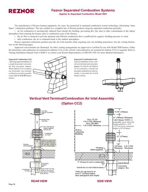
The manufacturer of <strong>Reznor</strong> heating equipment, for years, has pioneered in separated <strong>com</strong>bustion system technology, eliminating “open<br />
flame” <strong>com</strong>bustion problems. This has resulted in a <strong>com</strong>plete line of <strong>Reznor</strong> products using the separated <strong>com</strong>bustion principle-<br />
• air for <strong>com</strong>bustion is mechanically induced from outside the building, preventing dirt, lint, dust or other contaminants in the indoor<br />
atmosphere from entering the burner, pilot or <strong>com</strong>bustion zone of the furnace,<br />
• the air flow is metered to provide optimum and efficient <strong>com</strong>bustion that is unaffected by negative building pressure or wind,<br />
• after <strong>com</strong>bustion, the air is exhausted back to the outdoor atmosphere.<br />
<strong>Reznor</strong> separated <strong>com</strong>bustion products provide all of the benefits while requiring only one building penetration. See the venting illustration<br />
on the following pages.<br />
Approved vent terminals are illustrated. No other venting arrangements are approved or certified for use with Model SDH heaters. Either<br />
the horizontal vent/<strong>com</strong>bustion air terminal kit (Option CC6) or the vertical vent/<strong>com</strong>bustion air terminal kit (Option CC2) is required. Refer to<br />
Venting Installation Manual Form I-SDH-V or contact your <strong>Reznor</strong> Representative at 800-695-1901 for more detailed information.<br />
<strong>Separated</strong> <strong>Combustion</strong> Unit<br />
- Showing typical installation of<br />
a single horizontal vent terminal<br />
and concentric adapter.<br />
When Option CC6 is ordered,<br />
one horizontal vent terminal/<br />
<strong>com</strong>bustion air inlet assembly<br />
is provided for EACH furnace<br />
section.<br />
<strong>Separated</strong> <strong>Combustion</strong> Unit -<br />
Typical installation of one vertical<br />
vent terminal and concentric<br />
adapter. If vertical vent (Option<br />
CC2) is selected, a vertical vent<br />
terminal/<strong>com</strong>bustion-air inlet assembly<br />
is provided for EACH<br />
furnace section.<br />
<strong>Vertical</strong> Vent Terminal/<strong>Combustion</strong> Air Inlet Assembly<br />
(Option CC2)<br />
Vent (flue<br />
exhaust) Terminal<br />
9-3/8” (238mm)<br />
Double-Wall<br />
Vent Pipe<br />
Seal with silicone<br />
sealant supplied<br />
with the kit.<br />
<strong>Combustion</strong><br />
Air Inlets<br />
Wall or<br />
Adjoining<br />
Building<br />
Sizes 75-225<br />
4 ft (1.2M) Minimum<br />
Sizes 250-400A<br />
6 ft (1.8M) Minimum<br />
12” (305mm) Minimum<br />
Cold Climate NOTE: In<br />
geographic areas where the<br />
design ambient is -10°F<br />
(-23°C)or lower, minimum<br />
height is 24”(610mm).<br />
11” (279mm)<br />
Flashing<br />
(field-supplied)<br />
Shaded area respresents<br />
required continuous (no<br />
joints) section of doublewall<br />
vent pipe. Section of<br />
pipe may extend higher.<br />
Flashing<br />
(field-supplied)<br />
*18”<br />
(457mm)<br />
Minimum<br />
4 ft (1.2M)<br />
Maximum<br />
Roof<br />
Roof<br />
<strong>Combustion</strong><br />
Air Pipe<br />
Concentric<br />
Adapter<br />
Box<br />
Double-Wall Vent Pipe<br />
Attach to vent run no<br />
more than 6” (152mm)<br />
from the box.<br />
2” (51mm) if roof is <strong>com</strong>bustible<br />
Attach box to roof with brackets.<br />
*Inlet air cap must be at<br />
least 6” (152mm) higher<br />
than anticipated snow depth.<br />
(Top of Box)<br />
Concentric<br />
Adapter Box<br />
Page 36<br />
REAR VIEW<br />
SIDE VIEW
<strong>Reznor</strong> <strong>Separated</strong> <strong>Combustion</strong> <strong>Systems</strong> (cont’d)<br />
®<br />
Horizontal Vent Terminal/<strong>Combustion</strong> Air Inlet Assembly<br />
(Option CC6)<br />
Approved vent terminals are illustrated below. No other venting<br />
arrangements are approved or certified for use with <strong>Reznor</strong> separated<br />
<strong>com</strong>bustion heaters.<br />
Both the horizontal and vertical assemblies include: concentric<br />
adapter, screened exhaust or cap, inlet ring or inlet cap, rubber gasket<br />
ring and a tube of high temperature silicone rubber sealant; all shipped<br />
separately.<br />
One-piece<br />
“Terminal End”<br />
Vent Pipe<br />
Inlet Air<br />
Guard<br />
Minimum<br />
4” (102mm)<br />
Maximum<br />
16” (406mm)<br />
TOP VIEW<br />
2” (51mm) if wall is <strong>com</strong>bustible<br />
Attach box to wall with brackets.<br />
<strong>Combustion</strong> Air to Heater (seal joints)<br />
Exhaust<br />
Grill<br />
Minimum<br />
3” (76mm)<br />
Maximum<br />
6” (152mm)<br />
Wall<br />
1” (25mm)<br />
Minimum<br />
48” (1219mm)<br />
Maximum<br />
6”<br />
(152<br />
mm)<br />
Concentric<br />
Adapter<br />
Box Width<br />
Vent (Flue Exhaust) Pipe<br />
from heater (seal joints)<br />
Attach one-piece “terminal end” pipe to vent<br />
run no more than 6” (152mm) from the box.<br />
Distance between the<br />
Concentric Adapter Box<br />
and the Heater<br />
For Maximum Length, see TABLE 1 on page 2.<br />
Minimum length is 3 ft (.9M).<br />
Heater<br />
SIDE VIEW<br />
Building Overhang - Maximum 24” (610mm)<br />
Y<br />
Minimum<br />
Wall<br />
Adjoining Building<br />
X - Minimum*<br />
One-piece<br />
“Terminal End”<br />
Vent Pipe -<br />
Pitch to<br />
Drain<br />
3 ft (1M)<br />
Minimum<br />
Thimble<br />
<strong>Combustion</strong> Air Pipe<br />
- Pitch to Drain<br />
Secure Concentric Adapter<br />
Box to wall with brackets.<br />
Adjust so that the box has a<br />
slight downward slope to the<br />
outside.<br />
Rain water should drain out<br />
and not roll into the pipes.<br />
Building Projection<br />
Page 37