optional cooling coil cabinet with dx or chilled ... - Agencespl.com
optional cooling coil cabinet with dx or chilled ... - Agencespl.com
optional cooling coil cabinet with dx or chilled ... - Agencespl.com
- No tags were found...

You also want an ePaper? Increase the reach of your titles
YUMPU automatically turns print PDFs into web optimized ePapers that Google loves.
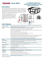
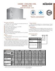
®OPTIONAL COOLING COIL CABINETWITH DX OR CHILLED WATER COILF<strong>or</strong> use <strong>with</strong> Models(C)RGB, RPB, (C)RGBL, <strong>or</strong> RPBLPage _____ of _____CUSTOMERCQSAGENCYCONVERGENTQUALITY SYSTEMPRODUCTPROCESSSTART-UPWARRANTYDescription/ApplicationIndirect-fired packaged Rezn<strong>or</strong> heating/makeup air systems, ModelSeries RGB, RPB, RGBL, RPBL, PGBL and SSCBL, are available <strong>with</strong> an<strong>optional</strong> <strong>cooling</strong> <strong>coil</strong> <strong>cabinet</strong> that houses a large finned surface refrigerant(DX) <strong>or</strong> <strong>chilled</strong> water <strong>cooling</strong> <strong>coil</strong>. Cooling <strong>coil</strong>s are available in capacitiesfrom 3 to over 40 tons (36 to 480 MBH). Depending on the size of thesystem, the <strong>cabinet</strong>s ac<strong>com</strong>modate <strong>coil</strong>s <strong>with</strong> a finned surface area from 4 to15 square feet. Large finned surface areas aid <strong>coil</strong> perf<strong>or</strong>mance by reducingface velocities, lowering <strong>coil</strong> pressure drops, and increasing <strong>cooling</strong> capacity.Cabinets are fully insulated <strong>with</strong> weatherproof construction f<strong>or</strong> outdo<strong>or</strong>application. Standard construction is single-wall 20 gauge galvalume steel.Optional double-wall <strong>cabinet</strong> construction is available. The <strong>cooling</strong> <strong>coil</strong> <strong>cabinet</strong>has a drain trough f<strong>or</strong> positive drainage under all operating conditions in<strong>com</strong>pliance <strong>with</strong> ASHRAE Standard 62-1989. The drain trough is provided<strong>with</strong> a 1" FPVC connection on the exteri<strong>or</strong> of the <strong>cabinet</strong>. Each side of the<strong>cooling</strong> <strong>coil</strong> <strong>cabinet</strong> has easily removable do<strong>or</strong> panels f<strong>or</strong> routine <strong>coil</strong> inspectionand cleaning. F<strong>or</strong> down discharge, an <strong>optional</strong> downturn plenum <strong>cabinet</strong><strong>with</strong> <strong>or</strong> <strong>with</strong>out discharge dampers is available.Refer to Tables 6 through 9 f<strong>or</strong> perf<strong>or</strong>mance data under entering airconditions of 80°F (drybulb) / 67°F (wetbulb) and 95°F (drybulb) / 75°F(wetbulb) The perf<strong>or</strong>mance data is certified in acc<strong>or</strong>dance <strong>with</strong> ARI Standard410.F<strong>or</strong> <strong>coil</strong> capacities not outlined in these tables, special <strong>coil</strong> requirements,<strong>or</strong> indo<strong>or</strong> <strong>cabinet</strong> installation, contact your Rezn<strong>or</strong> Sales Representative.Cooling Coil Selection ProcedureSelecting the proper <strong>cooling</strong> <strong>coil</strong> is vital to air handling equipmentperf<strong>or</strong>mance and cost. The c<strong>or</strong>rectly sized <strong>coil</strong> provides the desired dehumidificationand sensible <strong>cooling</strong> under all possible internal and externalloads that the building may experience. In <strong>or</strong>der to properly select the <strong>coil</strong>capacity, a detailed internal and external load analysis must be perf<strong>or</strong>med.Caution must be taken to ensure that the percentage of outside air broughtinto the building meets current codes. The percentage of outside air f<strong>or</strong> mostapplications is approximately 25%. Some current codes require greater percentagesof outside air, up to 100% f<strong>or</strong> densely populated structures wherecontaminants be<strong>com</strong>e a significant health risk, such as schools. The currentASHRAE re<strong>com</strong>mendations on proper percentages of outside air can befound in ASHRAE Standard 62-1999 “Ventilation f<strong>or</strong> Acceptable Indo<strong>or</strong>Air Quality”.Review the <strong>coil</strong> perf<strong>or</strong>mance tables f<strong>or</strong> general capacity data at standardoutside air (95°/75°F) and return air (80°/67°F) conditions. The preferredmethod of selection is to use the Rezn<strong>or</strong> Coil Selection Software. If youdo not have a copy, contact your local Rezn<strong>or</strong> Sales Representative.ControlsControls are not fact<strong>or</strong>y supplied <strong>with</strong> the <strong>coil</strong>s. Controls include allcondensing related equipment -- thermostatic expansion valves (TEV), auxiliaryconnections f<strong>or</strong> hot gas bypass, and hot gas bypass <strong>or</strong> liquid injectionvalves. See your local Rezn<strong>or</strong> Sales Representative f<strong>or</strong> re<strong>com</strong>mended TEV's.Coil distribut<strong>or</strong> details are in Table 4.Features● Weatherized, insulated <strong>cabinet</strong> is an integral part of a Rezn<strong>or</strong> ® heating/makeup air system (<strong>with</strong> either a fact<strong>or</strong>y-installed DX <strong>or</strong> <strong>chilled</strong> water<strong>cooling</strong> <strong>coil</strong>)● Single-wall <strong>cabinet</strong> construction (double-wall option available)● Cabinet includes access panels f<strong>or</strong> easy <strong>coil</strong> inspection <strong>or</strong> cleaning● Available f<strong>or</strong> standard refrigerant (DX) <strong>or</strong> <strong>chilled</strong> water <strong>coil</strong>~ Capacities from 3 to over 40 tons (36 to 480 MBH)~ 2, 3, 4 <strong>or</strong> 6 row <strong>coil</strong>s <strong>with</strong> 6, 8, 10, 12 <strong>or</strong> 14 fins per inch (fin thickness.0075") are standardAdditional Coil Options:~ Phenolic coatings~ Copper fins~ Stainless steel casingF<strong>or</strong>m RZ-NA-C-PO Page 38Table 1: Cabinet Option DesignationsCode DescriptionAU2 Cooling Coil Cabinet f<strong>or</strong> a Chilled Water CoilAU3 Cooling Coil Cabinet f<strong>or</strong> a DX CoilAU11 Cooling Coil Cabinet f<strong>or</strong> a Chilled Water Coil plus a DownturnPlenum CabinetAU12 Cooling Coil Cabinet f<strong>or</strong> a Chilled Water Coil plus a DownturnPlenum Cabinet <strong>with</strong> 2-Position Discharge DampersAU13 Cooling Coil Cabinet f<strong>or</strong> a DX Coil plus a Downturn PlenumCabinetAU14 Cooling Coil Cabinet f<strong>or</strong> a DX Coil plus a Downturn PlenumCabinet <strong>with</strong> 2-Position Discharge Dampers
Dimensional DataPage _____ of _____®Chilled Water Coil Cabinet - Options AU2, AU11, AU12D7/8 7/8Coil VentConnection(1/2” NPT)OpeningAB38-3/815-1/4Side ViewChilled WaterCoil CabinetReturnConnection(2-1/2” NPT)OpeningSupplyConnection(2-1/2” NPT)OpeningCoil DrainConnection(1/2” NPT)OpeningDrain PanConnection(1” FPVC)3/4 3/4Front ViewChilled WaterCoil Cabinet<strong>with</strong> H<strong>or</strong>izontalDischarge(Option AU2)44-1/4183/411-1/46-5/8GF (Inside Curb Cap)E (Curb Cap Length)C+23-1/8” (587mm)to length of unit <strong>or</strong>unit and <strong>cooling</strong> <strong>coil</strong> <strong>cabinet</strong>Discharge Damper Note: Thetwo-position discharge dampersin Option AU12 fit in the dischargeair opening. The dampermot<strong>or</strong> fits inside the downturn plenum<strong>cabinet</strong>.Side ViewDownturn PlenumCabinetOption AU11 <strong>or</strong>AU12Front ViewOptionalDownturn PlenumCabinet19-1/2 (Discharge Air)Table 2A. Dimensions (inches ± 1/8) and Approximate Weights (lbs)4-1/44-1/4 J (Discharge Air) 4-1/4CEFFurnace Without With Without WithSize A B C D Downturn Downturn Downturn Downturn G J(mbh) in. mm in. mm in. mm in. mm in. mm in. mm in. mm in. mm in. mm in. mm75, 100,12528 1/2 724 15 1/4 387 25 7/8 657 37 1/8 943 40 1,016 64 1,626 38 1/8 968 62 1/8 1,578 19 1/2 495 17 3/8 441150, 175 34 864 20 3/4 527 31 3/8 797 42 5/8 1,083 45 5/8 1,159 69 5/8 1,768 43 5/8 1,108 67 5/8 1,718 22 1/4 565 22 7/8 581200, 225 39 1/2 1,003 26 1/4 667 36 7/8 937 48 1/8 1,222 51 1,295 75 1,905 49 1/8 1,248 73 1/8 1,857 25 635 28 3/8 721250, 300,500, 60047 3/4 1,213 34 1/2 876 45 1/8 1,146 56 3/8 1,432 59 3/8 1,508 83 3/8 2,118 57 3/8 1,457 81 3/8 2,067 29 1/8 740 36 5/8 930350, 700,53 1/410501,353 40 1,016 50 5/8 1,286 62 1,575 64 7/8 1,648 88 7/8 2,257 63 1,600 87 2,210 31 7/8 810 42 1/8 1,070400, 800,58 3/412001,492 45 1/2 1,156 56 1/8 1,426 67 3/8 1,711 70 3/8 1,788 94 3/8 2,397 68 3/8 1,737 92 3/8 2,346 34 5/8 879 47 5/8 1,210F<strong>or</strong>m RZ-NA-C-PO Page 39
®Page _____ of _____Refrigerant R22 (DX) Coil Cabinet - Options AU3, AU13, AU14D28 A7/8 7/85-1/8BSide ViewDX CoilCabinetCoilHeaderHousingLiquid LineConnections(7/8” <strong>or</strong> 1-3/8”)3/4 3/4Drain PanOutlet(1” FPVC)Suction LineConnections(1-5/8” <strong>or</strong> 2-1/8”)12-1/2Front ViewDX Coil Cabinet<strong>with</strong> H<strong>or</strong>izontalDischarge(Option AU3)18 44-1/43/414-1/216-1/411-1/46-5/8GF (Inside of Curb Cap)E (Curb Cap Length)+23-1/8” (587mm)to length of unit <strong>or</strong>unit and <strong>cooling</strong> <strong>coil</strong> <strong>cabinet</strong>CLiquid LineConnectionKnockouts(AlternateLocations)2-3/83-1/23-1/4Side ViewDownturn PlenumCabinetOption AU13 <strong>or</strong>AU14Front ViewOptionalDownturn PlenumCabinetBottom ViewDX CoilCabinet19-1/2 (Discharge Air)Table 2B. Dimensions (inches ± 1/8) and Approximate Weights (lbs)4-1/44-1/4 J (Discharge Air) 4-1/4CDischarge Damper Note: The two-position discharge dampers in OptionAU14 fit in the discharge air opening. The damper mot<strong>or</strong> fits inside thedownturn plenum <strong>cabinet</strong>.EFFurnace Without With Without WithSize A B C D Downturn Downturn Downturn Downturn G J(mbh) in. mm in. mm in. mm in. mm in. mm in. mm in. mm in. mm in. mm in. mm75, 100,12528 1/2 724 15 1/4 387 25 7/8 657 37 1/8 943 40 1,016 64 1,626 38 1/8 968 62 1/8 1,578 19 1/2 495 17 3/8 441150, 175 34 864 20 3/4 527 31 3/8 797 42 5/8 1,083 45 5/8 1,159 69 5/8 1,768 43 5/8 1,108 67 5/8 1,718 22 1/4 565 22 7/8 581200, 225 39 1/2 1,003 26 1/4 667 36 7/8 937 48 1/8 1,222 51 1,295 75 1,905 49 1/8 1,248 73 1/8 1,857 25 635 28 3/8 721250, 300,500, 60047 3/4 1,213 34 1/2 876 45 1/8 1,146 56 3/8 1,432 59 3/8 1,508 83 3/8 2,118 57 3/8 1,457 81 3/8 2,067 29 1/8 740 36 5/8 930350, 700,53 1/410501,353 40 1,016 50 5/8 1,286 62 1,575 64 7/8 1,648 88 7/8 2,257 63 1,600 87 2,210 31 7/8 810 42 1/8 1,070400, 800,58 3/412001,492 45 1/2 1,156 56 1/8 1,426 67 3/8 1,711 70 3/8 1,788 94 3/8 2,397 68 3/8 1,737 92 3/8 2,346 34 5/8 879 47 5/8 1,210F<strong>or</strong>m RZ-NA-C-PO Page 40
Page _____ of _____®Overall Dimensions of unit <strong>with</strong> Cooling Coil Cabinet, <strong>with</strong> <strong>or</strong> <strong>with</strong>out downturn plenumTable 2C. Overall Dimensions of Model (C)RGB/RPB<strong>with</strong> Cooling Coil Cabinet, <strong>with</strong> <strong>or</strong> <strong>with</strong>out downturn plenumBADX COILHEADERHOUSING8”203mmBLOWERSECTIONFURNACEAIR FLOW44-1/4”1,124mmLEFT SIDE VIEWCOOLINGCOILCABINETOPTIONALDOWNTURNPLENUMFRONT VIEWOF OPTIONALDOWNTURNPLENUMUnit <strong>with</strong> CoolingUnit <strong>with</strong> CoolingCoil Cabinet onlyCoil Cabinet andDownturn PlenumA B BMODEL SIZE in. mm in. mm in. mm(C)RGB 75, 100 28 5/8 727 98 1/2 2,502 121 5/8 3,089(C)RGB 125 28 5/8 727 98 1/2 2,502 121 5/8 3,089<strong>or</strong> 150, 175 34 1/8 867 104 2,642 127 1/8 3,229RPB 200, 225 39 5/8 1,006 109 1/2 2,781 132 5/8 3,369250, 300 47 7/8 1,216 117 3/4 2,991 140 7/8 3,578350 53 3/8 1,356 123 3/8 3,134 146 1/2 3,721400 58 7/8 1,495 128 3/4 3,270 151 7/8 3,858Table 2D. Overall Dimensions of Model (C)RGBL/RPBL<strong>with</strong> Cooling Coil Cabinet, <strong>with</strong> <strong>or</strong> <strong>with</strong>out downturn plenumBADX COILHEADERHOUSING8”203mmBLOWERCABINETDUCTFURNACEDUCTFURNACEDUCTFURNACE44-1/4”1,124mmAIR FLOWAIR FLOWAIR FLOWOPTIONALRETURN AIROPENINGLEFT SIDE VIEWCOOLING OPTIONALCOIL DOWNTURNCABINET PLENUMFRONT VIEWUnit <strong>with</strong> CoolingUnit <strong>with</strong> CoolingCoil Cabinet onlyCoil Cabinet andDownturn PlenumA B BMODEL SIZE in. mm in. mm in. mm400 58 7/8 1,495 150 3/8 3,820 173 1/2 4,407(C)RGB 500, 600 47 1/8 1,197 165 3/8 4,201 188 1/2 4,788<strong>or</strong> 700 53 3/8 1,356 171 4,343 194 1/8 4,931RPB 800 58 7/8 1,495 176 3/8 4,480 199 1/2 5,0671050 53 3/8 1,356 197 5,004 220 1/8 5,5911200 58 7/8 1,495 202 3/8 5,140 225 1/2 5,728F<strong>or</strong>m RZ-NA-C-PO Page 41
Table 3. Coil Dimensionsand Weights(table applies to bothtypes of <strong>coil</strong>s)®Page _____ of _____Dimensional Data (cont'd)A B Maximum Dry Coil WeightFurnace Fin Coil Finned 6 fpi 8 fpi 10 fpi 12 fpi 14 fpiSize Length Length Surface Area 2.4 fins/cm 3 fins/cm 4 fins/cm 4.7 fins/cm 5.5 fins/cm(mbh) in mm in mm sq. ft. M 2 lbs. kg lbs. kg lbs. kg lbs. kg lbs. kg75, 100, 125 22 559 24 610 5 0.46 111 50 118 54 126 57 135 61 145 66150, 175 30 762 32 813 6.9 0.64 137 62 148 67 160 73 172 78 185 84200, 225 37 940 39 991 8.5 0.79 162 73 175 79 189 86 204 93 220 100250, 300, 500, 600 49 1,245 51 1,295 11.2 1.04 203 92 221 100 240 109 260 118 281 127350, 700, 1050 57 1,448 59 1,499 13.1 1.22 231 105 252 114 274 124 297 135 321 146400, 800, 1200 65 1,651 67 1,702 14.9 1.38 259 117 283 128 308 140 334 152 361 164Chilled Water Coil(Options LC 25-64 to be selected <strong>with</strong>Cabinet Option AU2, AU11, <strong>or</strong> AU12)10MaximumTop View2-51/647-7/32BA45°1/2” NPT Fitting<strong>with</strong> Plug34-1/233FHFront View2-1/2” NPTconnection(All Sizes)SideView61/2” NPT Fitting <strong>with</strong> PlugDX Coil(Options LX 25-84 to be selected <strong>with</strong>Cabinet Option AU3, AU13, <strong>or</strong> AU14)10MaximumTop ViewSuction Line ConnectionsØ2-1/8 <strong>or</strong> 1-5/8 (See Table 4)B3A These connections are noton single circuit <strong>coil</strong>s.AA17/32Distribut<strong>or</strong>Inlet(liquid line)Connection(s)Note: Positionedvertically down.SideView1134-1/225, 30 <strong>or</strong> 32.5FHFront ViewNote: See table 4f<strong>or</strong> dimensionsf<strong>or</strong> Distribut<strong>or</strong> Inletand Suction LineConnectionsA23-1/26SuctionLineConnectionsTable 4. DX (R22) Coils - Typical Circuiting, Distribut<strong>or</strong> and Suction Line Details*Coil Distribut<strong>or</strong> Circuits Feeder Sp<strong>or</strong>lan ByronCapacity Suction Inlet No. of per Tube Distribut<strong>or</strong> Distribut<strong>or</strong>Range Connection Connection(s) Connection(s) Distribut<strong>or</strong>s Distribut<strong>or</strong> Diameter Style Style(mbh) Type [in] [in] [qty] [qty] [in] [#] [#]0 - 90 OD Solder 1 5/8 1 3/8 1 11 1/4 1117 14091 - 200 OD Solder 1 5/8 7/8 2 05 / 06 1/4 1112 117201 - 400 OD Solder 1 5/8 <strong>or</strong> 2 1/8 7/8 2 05 / 06 5/16 1113 120401 - 480 OD Solder 2 1/8 1 3/8 2 11 1/4 <strong>or</strong> 5/16 1117 <strong>or</strong> 1126 140 <strong>or</strong> 160481 - 600 OD Solder 2 1/8 1 3/8 2 11 5/16 1126 160F<strong>or</strong>m RZ-NA-C-PO Page 42*Connection sizes and circuitingdimensions are “typical.” Actualdimensions are displayed on theCoil Selection Rep<strong>or</strong>t fromRezn<strong>or</strong> Coil Select<strong>or</strong> Software.
Table 5A. Heating and Cooling Airflow Ranges - “B” Cabinet ModelsCoolingStandardHeating Actual AirflowAirflowMaximumWith Model RPB Model RGB Model CRGB (550 SFPM)Furnace Maximum Minimum Maximum Minimum Maximum Minimum (2.8 M/s)Size acfm aM 3 /hr acfm aM 3 /hr acfm aM 3 /hr acfm aM 3 /hr acfm aM 3 /hr acfm aM 3 /hr scfm sM 3 /hr75 - - - - 720 1,223 600 1,019 740 1,257 615 1,045H75 - - - - 2,645 4,494 705 1,198 2,750 4,672 785 1,3342,780 4,723100 - - - - 940 1,597 780 1,325 940 1,597 775 1,317H100 - - - - 3,400 5,776 940 1,597 3,175 5,394 940 1,5972,780 4,723125 1,230 2,090 1,025 1,741 1,175 1,996 980 1,665 1,170 1,988 965 1,639H125 3,800 6,456 1,230 2,090 3,800 6,456 1,175 1,996 3,570 6,065 1,170 1,9882,780 4,723150 1,480 2,514 1,230 2,090 1,410 2,396 1,175 1,996 - - - -H150 4,700 7,985 1,480 2,514 4,700 7,985 1,410 2,396 - - - -3,780 6,422175 1,725 2,931 1,440 2,446 1,645 2,795 1,370 2,328 1,570 2,667 1,290 2,192H175 5,000 8,495 1,725 2,931 5,000 8,495 1,645 2,795 4,450 7,560 1,570 2,6673,780 6,422200 1,975 3,355 1,645 2,795 1,880 3,194 1,565 2,659 - - - -H200 5,100 8,665 1,975 3,355 5,100 8,665 1,880 3,194 - - - -4,670 7,934225 2,220 3,772 1,850 3,143 2,115 3,593 1,765 2,999 2,095 3,559 1,725 2,931H225 5,150 8,750 2,220 3,772 5,150 8,750 2,115 3,593 4,750 8,070 2,095 3,5594,670 7,934250 2,465 4,188 2,055 3,491 2,350 3,993 1,960 3,330 2,335 3,967 1,940 3,296H250 5,800 9,854 2,465 4,188 5,800 9,854 2,350 3,993 5,500 9,344 2,355 4,0016,180 10,499300 2,960 5,029 2,465 4,188 2,820 4,791 2,350 3,993 2,825 4,800 2,330 3,959H300 6,300 10,703 2,960 5,029 6,300 10,703 2,820 4,791 5,890 10,007 2,825 4,8006,180 10,499350 3,455 5,870 2,880 4,893 3,295 5,598 2,745 4,664 3,300 5,607 2,715 4,613H350 6,800 11,553 3,455 5,870 6,800 11,553 3,295 5,598 6,415 10,899 3,300 5,6077,190 12,215400 3,950 6,711 3,290 5,590 3,765 6,397 3,135 5,326 3,770 6,405 3,105 5,275H400 7,100 12,063 3,950 6,711 7,100 12,063 3,765 6,397 6,635 11,273 3,770 6,4058,200 13,931Table 5A. Heating and Cooling Airflow Ranges - “BL” Cabinet ModelsModels (C)RGBL, RPBL, SSCBL, PGBLCoolingStandardHeating Actual Airflow AirflowMaximumWith Maximum Minimum (550 SFPM)Furnace(2.8 M/s)Size acfm aM 3 /hr acfm aM 3 /hr scfm sM 3 /hr400 14,000 23,785 3,300 5,607 8,200 13,931500 12,000 20,387 3,700 6,286 6,180 10,499600 12,500 21,237 4,450 7,560 6,180 10,499700 13,500 22,936 5,200 8,835 7,190 12,215800 13,500 22,936 5,900 10,024 8,200 13,9311050 13,500 22,936 6,500 11,043 7,190 12,2151200 13,500 22,936 7,400 12,572 8,200 13,931Using the Coil Perf<strong>or</strong>mance Tables (Tables 6, 7, 8, and 9)The perf<strong>or</strong>mance data tables on the following pages can be used todetermine if a Rezn<strong>or</strong> <strong>coil</strong> is available to meet your requirements. Follow thesteps below bef<strong>or</strong>e submitting a Coil Option Specification Request F<strong>or</strong>m.The preferred method of selection is to use the Rezn<strong>or</strong> Coil SelectionSoftware. If you do not have a copy, contact your Rezn<strong>or</strong> Representative.Steps:1. Enter the Table f<strong>or</strong> your <strong>cooling</strong> application – Refrigerant Coils, R22 -Table 6 <strong>or</strong> 7; Chilled Water Coils - Table 8 <strong>or</strong> 9.2. Choose the table which best matches your entering air conditions. Tables6 and 8 are f<strong>or</strong> the condition of 80°F db / 67°F wb. This is a standard <strong>coil</strong>rating condition f<strong>or</strong> return air applications. All Rezn<strong>or</strong> <strong>coil</strong>s are rated toARI Standard 410. Tables 7 and 9 are f<strong>or</strong> the condition of 95°F db / 75°Fwb. This is an accepted general condition f<strong>or</strong> 100% outside air applications.If your design condition is different from these <strong>or</strong> your operatingparameters vary from those specified, you can only estimate perf<strong>or</strong>mancefrom these data tables.3. Find your furnace model in the left-most column of the table.F<strong>or</strong>m RZ-NA-C-PO Page 43Page _____ of _____Notes f<strong>or</strong> Tables 5A and B:1) Calculate Coil Face Velocity as : [Airflow (scfm [sM 3 /hr]) / Finned Coil Surface Area (sq.ft. [M 2 ])]2) A general rule of thumb f<strong>or</strong> required airflow is 400 scfm (680sM 3 /hr) per ton of <strong>cooling</strong>f<strong>or</strong> return air applications. This value will be much less f<strong>or</strong> outside air applications.3) To avoid the possibility of condensate blow-off, the <strong>coil</strong> face velocities should not exceed550 sfpm.4) Conversion to standard air flow is required above 1500 ft. To convert from actual airflow(acfm) to standard airflow (scfm), see Conversion to Standard Airflow.5) If the <strong>coil</strong> <strong>cabinet</strong> is being <strong>or</strong>dered <strong>with</strong> an indo<strong>or</strong> unit (Model SSCBL <strong>or</strong> PGBL), contactyour Sales Representative f<strong>or</strong> details on the required field-supplied transition.4. The table contains capacities at the minimum and maximum suggestedairflow f<strong>or</strong> each furnace model, see column 2.Your airflow in Standard CFM (SCFM) should fall <strong>with</strong>in this range. SeeConversion to Standard Airflow to determine scfm from the actualairflow (ACFM). ACFM should be used when selecting fan and mot<strong>or</strong>requirements.F<strong>or</strong> <strong>coil</strong> selections the imp<strong>or</strong>tant parameter is not the volume of air over the<strong>coil</strong>, but the mass flow over the <strong>coil</strong>. This requires knowledge of thevolume flow at “standard conditions” (SCFM).5. Determine the maximum capacity available from a specific <strong>coil</strong> by enteringthe Table and finding the total capacity (mbh) f<strong>or</strong> a 6 row, 12 fins per in(fpi) <strong>coil</strong> at maximum airflow (scfm). If your application if less than thepublished capacity f<strong>or</strong> the design conditions, use the Selection Requirementssection to <strong>com</strong>plete your request f<strong>or</strong>m. If your application requiresa <strong>coil</strong> capacity greater than determined above, you may require a largerfurnace and ac<strong>com</strong>panying <strong>coil</strong> <strong>cabinet</strong> to achieve the necessary <strong>coil</strong> size.Your Sales Representative will be able to assist you in this selection.
®Using the Coil Perf<strong>or</strong>mance Tables (Tables 6, 7, 8, and 9) cont’dPage _____ of _____Example : (Refrigerant Coil)Furnace model ....................... RPB-200Design conditions ................. 90/70°FApplication airflow ............... 3500 scfmCapacity required .................. 120 mbhEvap<strong>or</strong>at<strong>or</strong> Temperature ........ 45°FLiquid Temperature ............... 100°FStep 1 Design is 90/70°F. Be conservative, enter the table f<strong>or</strong> 80/67°FStep 2 Furnace Model is a size 200Step 3 Determine the maximum capacity f<strong>or</strong> a size 200 <strong>cabinet</strong> = 184 mbhSince the requirement of 120 mbh falls <strong>with</strong>in the tabulated capacity of 184 mbh f<strong>or</strong>entering conditions of 80/67°F, a standard <strong>coil</strong> will meet the application requirements.Complete a Coil Option Specification Request F<strong>or</strong>m (see page 12) and submit it to yourRezn<strong>or</strong> Sales Representative.Table 6. Perf<strong>or</strong>mance of R-22 Refrigerant (DX) Cooling Coils (Options LX25 - LX84)Perf<strong>or</strong>mance based on entering air conditions – 80°F Dry Bulb and 67°F Wet BulbCapacity based on 80°F EDB, 67°F EWB, 45°F Saturated Suction (Evap<strong>or</strong>at<strong>or</strong>), 100°F LiquidFurnaceModels75, 100,125150, 175200, 225250, 300,500, 600350, 700,1050400, 800,12004 Row 6 RowCooling Face Fin Coil CoilAirflow Velocity Spacing Total Sens. DB WB APD Weight Total Sens. DB WB APD Weight(scfm) (sfpm) (fpi) (mbh) (mbh) (deg F) (deg F) (in. w.c.) (lbs) (mbh) (mbh) (deg F) (deg F) (in. w.c.) (lbs)1360 270 8 30 27 61 60 0.13 88 48 35 56 56 0.21 11810 33 29 61 60 0.17 94 52 36 55 55 0.26 12612 35 30 60 59 0.20 100 54 37 54 54 0.32 1352780 550 8 45 45 64 62 0.42 88 77 61 59 58 0.71 11810 50 50 63 62 0.50 94 84 65 58 58 0.80 12612 53 52 63 62 0.59 100 88 68 57 57 0.98 1351860 270 8 52 41 60 59 0.14 110 76 52 54 54 0.21 14810 56 43 59 58 0.18 118 81 54 53 53 0.27 16012 60 45 58 57 0.21 126 84 56 52 52 0.32 1723780 550 8 77 68 63 61 0.44 110 122 90 58 57 0.71 14810 85 74 62 60 0.53 118 132 96 56 56 0.85 16012 92 79 61 60 0.62 126 140 100 56 55 0.98 1722290 270 8 71 52 59 57 0.14 128 100 66 53 53 0.21 17510 77 56 57 57 0.18 137 105 69 52 52 0.26 18912 82 59 56 56 0.21 147 110 71 51 51 0.32 2044670 550 8 107 88 63 60 0.47 128 162 116 57 56 0.71 17510 119 97 61 59 0.57 137 174 123 56 55 0.80 18912 128 103 60 59 0.62 147 184 127 55 55 0.98 2043030 270 8 105 74 58 56 0.14 159 139 90 53 52 0.21 22110 114 79 56 55 0.18 172 146 94 51 51 0.27 24012 120 83 55 55 0.21 185 152 96 50 50 0.32 2606180 550 8 161 124 61 59 0.47 159 226 156 57 56 0.71 22110 177 134 60 58 0.56 172 240 165 55 55 0.85 24012 190 143 59 58 0.65 185 252 170 54 54 0.98 2603530 270 8 128 88 57 56 0.14 180 164 106 52 52 0.21 25210 139 95 55 55 0.18 195 173 111 51 51 0.26 27412 147 99 54 54 0.21 210 178 114 50 50 0.32 2977190 550 8 197 148 61 59 0.47 180 262 182 57 56 0.71 25210 216 159 60 58 0.56 195 281 193 55 55 0.80 27412 231 170 58 57 0.65 210 294 201 54 54 0.98 2974020 270 8 149 101 57 55 0.14 202 188 122 57 55 0.21 28310 163 109 55 54 0.18 219 197 127 51 51 0.27 30812 172 115 54 53 0.21 236 203 129 50 50 0.32 3348200 550 8 231 170 61 58 0.47 202 298 209 56 56 0.71 28310 252 184 59 58 0.56 219 316 219 55 55 0.85 30812 270 196 58 57 0.65 236 329 227 54 54 0.98 334CONVERSIONS:1 m 3 /s = 2120 cfm1 m/s = 197 fpm1 ton <strong>cooling</strong> = 1/12 mbh1 kW = 3.41 mbh(°F-32) 5/9 = °C1 in wc = 249 pascals1 lb = 0.45 kgNOTES :1) Coil Perf<strong>or</strong>mance Data certified in acc<strong>or</strong>dance <strong>with</strong> ARI Standard 4102) Weight is f<strong>or</strong> dry <strong>coil</strong>3) Maximum re<strong>com</strong>mended <strong>coil</strong> face velocity is 550 sfpm4) Consult your Sales Representative f<strong>or</strong> special <strong>coil</strong> requirementsF<strong>or</strong>m RZ-NA-C-PO Page 44
Page _____ of _____®Table 7. Perf<strong>or</strong>mance of R-22 Refrigerant (DX) Cooling Coils (Options LX25 - LX84)Perf<strong>or</strong>mance based on entering air conditions – 95°F Dry Bulb and 75°F Wet BulbCapacity based on 95°F EDB, 75°F EWB, 45°F Saturated Suction (Evap<strong>or</strong>at<strong>or</strong>), 100°F LiquidFurnaceModels75, 100,125150, 175200, 225250, 300,500, 600350, 700,1050400, 800,12004 Row 6 RowCooling Face Fin Coil CoilAirflow Velocity Spacing Total Sens. DB WB APD Weight Total Sens. DB WB APD Weight(scfm) (sfpm) (fpi) (mbh) (mbh) (deg F) (deg F) (in. w.c.) (lbs) (mbh) (mbh) (deg F) (deg F) (in. w.c.) (lbs)1360 270 8 56 42 66 64 0.15 88 83 54 59 58 0.22 11810 60 45 64 63 0.18 94 88 56 57 57 0.27 12612 64 47 63 62 0.22 100 92 58 55 55 0.32 1352780 550 8 82 71 71 68 0.46 88 135 94 64 62 0.73 11810 91 78 69 67 0.55 94 147 101 61 61 0.87 12612 98 83 67 66 0.65 100 156 105 60 60 1.01 1351860 270 8 91 62 64 62 0.15 110 125 78 56 56 0.22 14810 99 67 62 60 0.18 118 132 82 54 54 0.27 16012 105 70 60 59 0.22 126 137 84 53 53 0.32 1723780 550 8 138 105 69 66 0.46 110 204 136 62 60 0.73 14810 152 115 67 65 0.55 118 220 145 60 59 0.87 16012 164 122 65 64 0.65 126 232 151 58 58 1.01 1722290 270 8 122 80 63 61 0.15 128 160 98 55 55 0.22 17510 132 86 60 59 0.18 137 169 103 53 53 0.27 18912 139 90 59 58 0.22 147 175 106 52 52 0.32 2044670 550 8 186 135 68 65 0.46 128 203 171 61 60 0.73 17510 205 147 66 64 0.55 137 281 182 59 58 0.87 18912 220 157 64 62 0.65 147 295 189 57 57 1.01 2043030 270 8 173 110 61 60 0.15 159 218 132 55 54 0.22 22110 188 118 59 58 0.18 172 228 138 53 53 0.27 24012 198 124 57 57 0.22 185 235 142 52 52 0.32 2606180 550 8 267 186 67 64 0.46 159 350 229 61 60 0.73 22110 293 202 64 62 0.55 172 372 239 59 58 0.87 24012 314 215 63 61 0.65 185 387 248 58 58 1.01 2603530 270 8 207 130 61 59 0.15 180 254 154 55 54 0.22 25210 224 140 58 57 0.18 195 265 160 53 53 0.27 27412 236 147 56 56 0.22 210 273 164 52 52 0.32 2977190 550 8 319 217 67 63 0.46 180 399 263 61 60 0.73 25210 348 238 64 62 0.55 195 424 277 59 59 0.87 27412 371 252 63 61 0.65 210 440 287 58 58 1.01 2974020 270 8 239 150 60 59 0.15 202 287 174 55 54 0.22 28310 258 162 58 57 0.18 219 300 182 53 53 0.27 30812 272 169 56 56 0.22 236 308 185 52 52 0.32 3348200 550 8 366 250 67 63 0.46 202 448 296 62 60 0.73 28310 397 272 64 62 0.55 219 484 316 59 59 0.87 30812 423 287 62 61 0.65 236 510 329 58 58 1.01 334CONVERSIONS:1 m 3 /s = 2120 cfm1 m/s = 197 fpm1 ton <strong>cooling</strong> = 1/12 mbh1 kW = 3.41 mbh(°F-32) 5/9 = °C1 in wc = 249 pascals1 lb = 0.45 kgNOTES :1) Coil Perf<strong>or</strong>mance Data certified in acc<strong>or</strong>dance <strong>with</strong> ARI Standard 4102) Weight is f<strong>or</strong> dry <strong>coil</strong>3) Maximum re<strong>com</strong>mended <strong>coil</strong> face velocity is 550 sfpm4) Consult your Sales Representative f<strong>or</strong> special <strong>coil</strong> requirementsF<strong>or</strong>m RZ-NA-C-PO Page 45
®Page _____ of _____Table 8. Perf<strong>or</strong>mance of Chilled Water Cooling Coils (Options LC25 - LC64)Perf<strong>or</strong>mance based on entering air conditions – 80°F Dry Bulb and 67°F Wet BulbCapacity based on 80°F EDB, 67°F EWB, 45°F Entering Water, 70 GPMFurnaceModels75, 100,125150, 175200, 225250, 300,500, 600350, 700,1050400, 800,12004 Row6 RowFace Fin Coil CoilAirflow Velocity Spacing Total Sens. DB WB APD FPD Weight Total Sens. DB WB APD FPD Weight(scfm) (sfpm) (fpi) (mbh) (mbh) (deg F) (deg F) (in. w.c.) (ft. w.c.) (lbs) (mbh) (mbh) (deg F) (deg F) (in. w.c.) (ft. w.c.) (lbs)1360 270 8 60 39 53 52 0.14 5.4 88 71 45 49 49 0.21 7.1 11810 65 42 52 51 0.17 5.4 94 75 47 48 48 0.26 7.1 12612 68 44 50 50 0.20 5.4 100 78 49 47 47 0.30 7.1 1352780 550 8 91 64 59 57 0.46 5.4 88 115 78 54 53 0.68 7.1 11810 100 70 57 55 0.54 5.4 94 124 83 53 52 0.82 7.1 12612 107 74 56 55 0.63 5.4 100 130 87 51 51 0.95 7.1 1351860 270 8 82 54 54 53 0.14 6.0 110 97 62 50 49 0.21 8.0 14810 88 57 52 51 0.17 6.0 118 102 65 48 48 0.26 8.0 16012 92 60 51 50 0.20 6.0 126 105 66 47 47 0.30 8.0 1723780 550 8 122 86 59 57 0.46 6.0 110 155 105 55 54 0.68 8.0 14810 134 94 57 56 0.54 6.0 118 166 112 53 53 0.82 8.0 16012 143 100 56 55 0.63 6.0 126 175 117 52 52 0.95 8.0 1722290 270 8 100 66 54 53 0.14 6.6 128 118 76 50 50 0.21 8.8 17510 107 70 52 51 0.17 6.6 137 124 79 48 48 0.26 8.8 18912 113 73 51 50 0.20 6.6 147 129 81 48 48 0.30 8.8 2044670 550 8 149 106 59 57 0.46 6.6 128 188 128 55 54 0.68 8.8 17510 162 115 57 56 0.54 6.6 137 201 136 53 53 0.82 8.8 18912 173 122 56 55 0.63 6.6 147 212 142 52 52 0.95 8.8 2043030 270 8 130 86 54 53 0.14 7.5 159 155 100 50 50 0.21 10.2 22110 140 92 52 52 0.17 7.5 172 163 104 49 49 0.26 10.2 24012 148 96 51 51 0.20 7.5 185 169 107 48 48 0.30 10.2 2606180 550 8 192 138 59 57 0.46 7.5 159 241 167 55 54 0.68 10.2 22110 210 150 58 56 0.54 7.5 172 259 178 54 53 0.82 10.2 24012 224 159 56 55 0.63 7.5 185 273 185 53 52 0.95 10.2 2603530 270 8 150 100 54 53 0.14 8.0 180 179 115 50 50 0.21 11.0 25210 162 107 52 52 0.17 8.0 195 188 120 49 49 0.26 11.0 27412 171 111 51 51 0.20 8.0 210 196 124 48 48 0.30 11.0 2977190 550 8 220 159 59 57 0.46 8.0 180 276 192 56 55 0.68 11.0 25210 240 173 58 56 0.54 8.0 195 296 204 54 54 0.82 11.0 27412 256 183 57 56 0.63 8.0 210 312 213 53 53 0.95 11.0 2974020 270 8 170 113 54 53 0.14 8.6 202 202 130 50 50 0.21 11.9 28310 183 120 53 52 0.17 8.6 219 213 136 49 49 0.26 11.9 30812 193 126 51 51 0.20 8.6 236 221 140 48 48 0.30 11.9 3348200 550 8 247 180 60 58 0.46 8.6 202 309 216 56 55 0.68 11.9 28310 269 195 58 57 0.54 8.6 219 331 230 54 54 0.82 11.9 30812 286 207 57 56 0.63 8.6 236 349 240 53 53 0.95 11.9 334CONVERSIONS:1 m 3 /s = 2120 cfm1 m/s = 197 fpm1 ton <strong>cooling</strong> = 1/12 mbh1 kW = 3.41 mbh(°F-32) 5/9 = °C1 in wc = 249 pascals1 lb = 0.45 kgNOTES :1) Coil Perf<strong>or</strong>mance Data certified in acc<strong>or</strong>dance <strong>with</strong> ARI Standard 4102) Weight is f<strong>or</strong> dry <strong>coil</strong>3) Maximum re<strong>com</strong>mended <strong>coil</strong> face velocity is 550 sfpm4) Consult your Sales Representative f<strong>or</strong> special <strong>coil</strong> requirementsF<strong>or</strong>m RZ-NA-C-PO Page 46
Table 9. Perf<strong>or</strong>mance of Chilled Water Cooling Coils(Options LC25 - LC64)Perf<strong>or</strong>mance based on entering air conditions – 95°F Dry Bulb and 75°F Wet BulbCapacity based on 95°F EDB, 75°F EWB, 45°F Entering Water, 70 GPMFurnaceModels75, 100,125150, 175200, 225250, 300,500, 600350, 700,1050400, 800,1200Page _____ of _____4 Row 6 RowFace Fin Coil CoilAirflow Velocity Spacing Total Sens. DB WB APD FPD Weight Total Sens. DB WB APD FPD Weight(scfm) (sfpm) (fpi) (mbh) (mbh) (deg F) (deg F) (in. w.c.) (ft. w.c.) (lbs) (mbh) (mbh) (deg F) (deg F) (in. w.c.) (ft. w.c.) (lbs)1360 270 8 89 56 58 56 0.14 5.4 88 106 64 52 51 0.21 7.1 11810 96 59 55 54 0.17 5.4 94 111 67 50 50 0.26 7.1 12612 101 62 53 53 0.20 5.4 100 115 69 49 49 0.30 7.1 1352780 550 8 134 90 65 62 0.46 5.4 88 171 110 59 57 0.68 7.1 11810 147 98 63 60 0.54 5.4 94 183 117 57 56 0.82 7.1 12612 157 104 61 59 0.63 5.4 100 193 122 55 55 0.95 7.1 1351860 270 8 121 75 58 56 0.14 6.0 110 144 87 52 52 0.21 8.1 14810 130 81 55 54 0.17 6.0 118 151 91 50 50 0.26 8.1 16012 137 84 53 53 0.20 6.0 126 156 94 49 49 0.30 8.1 1723780 550 8 180 122 66 62 0.46 6.0 110 228 148 59 58 0.68 8.1 14810 197 132 63 61 0.54 6.0 118 245 157 57 56 0.82 8.1 16012 210 140 61 59 0.63 6.0 126 258 164 55 55 0.95 8.1 1722290 270 8 148 93 58 56 0.14 6.6 128 176 107 52 52 0.21 8.9 17510 159 99 55 55 0.17 6.6 137 185 112 50 50 0.26 8.9 18912 168 104 54 53 0.20 6.6 147 192 115 49 49 0.30 8.9 2044670 550 8 219 149 66 62 0.46 6.6 128 276 181 60 58 0.68 8.9 17510 239 162 63 61 0.54 6.6 137 297 192 57 57 0.82 8.9 18912 255 172 61 60 0.63 6.6 147 313 200 56 55 0.95 8.9 2043030 270 8 193 121 58 57 0.14 7.5 159 230 141 53 52 0.21 10.1 22110 208 130 56 55 0.17 7.5 172 242 147 51 51 0.26 10.1 24012 219 136 54 54 0.20 7.5 185 251 151 49 48 0.30 10.1 2606180 550 8 282 194 66 63 0.46 7.5 159 355 234 60 59 0.68 10.1 22110 307 211 64 61 0.54 7.5 172 381 249 58 57 0.82 10.1 24012 328 223 62 60 0.63 7.5 185 401 260 57 56 0.95 10.1 2603530 270 8 223 141 59 57 0.14 8.0 180 265 162 53 52 0.21 11.0 25210 240 150 56 55 0.17 8.0 195 279 170 51 51 0.26 11.0 27412 253 157 54 54 0.20 8.0 210 290 175 50 50 0.30 11.0 2977190 550 8 322 224 66 63 0.46 8.0 180 405 270 61 59 0.68 11.0 25210 351 243 64 62 0.54 8.0 195 434 286 59 58 0.82 11.0 27412 374 258 62 61 0.63 8.0 210 457 299 57 57 0.95 11.0 2974020 270 8 252 159 59 57 0.14 8.6 202 299 184 53 53 0.21 11.8 28310 271 170 56 55 0.17 8.6 219 315 192 51 51 0.26 11.8 30812 285 178 55 54 0.20 8.6 236 328 198 50 50 0.30 11.8 3348200 550 8 362 253 67 63 0.46 8.6 202 452 304 61 60 0.68 11.8 28310 393 274 64 62 0.54 8.6 219 485 323 59 58 0.82 11.8 30812 418 291 63 61 0.63 8.6 236 511 336 57 57 0.95 11.8 334®CONVERSIONS:1 m 3 /s = 2120 cfm1 m/s = 197 fpm1 ton <strong>cooling</strong> = 1/12 mbh1 kW = 3.41 mbh(°F-32) 5/9 = °C1 in wc = 249 pascals1 lb = 0.45 kgNOTES :1) Coil Perf<strong>or</strong>mance Data certified in acc<strong>or</strong>dance <strong>with</strong> ARIStandard 4102) Weight is f<strong>or</strong> dry <strong>coil</strong>3) Maximum re<strong>com</strong>mended <strong>coil</strong> face velocity is 550 sfpm4) Consult your Sales Representative f<strong>or</strong> special <strong>coil</strong> requirementsCoil Selection RequirementsA. Required Application Inf<strong>or</strong>mationF<strong>or</strong> any <strong>coil</strong> selection the following inf<strong>or</strong>mation is required;● Cabinet option number based on the furnace model. (See the CabinetOption Designations)● Airflow in standard cubic feet per minute (scfm). (F<strong>or</strong> conversion fromactual to standard see Conversion to Standard Airflow)Note: To avoid conditions fav<strong>or</strong>able to condensate blow-off, equipmentshould be selected so that <strong>coil</strong> face velocities DO NOT exceed 550 sfpmif the <strong>coil</strong> will experience a latent load.● Conditions (DB/WB) temperatures entering the <strong>coil</strong>● Cooling capacity requirements in MBH <strong>or</strong> TonsB. Required Chilled Water Coil Inf<strong>or</strong>mationF<strong>or</strong> water <strong>coil</strong>s the following additional inf<strong>or</strong>mation must be supplied;● Entering fluid temperature, °F● Leaving fluid temperature, °F <strong>or</strong> fluid flow rate in gallons per minute(gpm)● Percentage of glycol and type (ethylene <strong>or</strong> propylene glycol)Note: F<strong>or</strong> water <strong>coil</strong> applications where temperatures may fall below 32°F,<strong>coil</strong>s should be drained per standard maintenance procedures. If a glycol isused, always test the glycol percentage pri<strong>or</strong> to winter months to ensureadequate protection against freezing.● Maximum allowable fluid-side pressure drop through the <strong>coil</strong>, (ft w.c.)F<strong>or</strong>m RZ-NA-C-PO Page 47
®Page _____ of _____Coil Selection Requirements (cont'd)C. Required R22 Refrigerant Coil Inf<strong>or</strong>mationF<strong>or</strong> refrigerant <strong>coil</strong>s the following additional inf<strong>or</strong>mation must be supplied;● Evap<strong>or</strong>at<strong>or</strong> temperature, °F● Liquid temperature, °F● Consult the fact<strong>or</strong>y f<strong>or</strong> special circuiting <strong>or</strong> refrigerantsD. Special RequirementsThe following special options are available on all <strong>coil</strong> types and sizes.● Phenolic coatings● Stainless steel <strong>coil</strong> casing material● Copper finsNote: F<strong>or</strong> special requirements not listed here, contact your Rezn<strong>or</strong> SalesRepresentative.E. Entering Air ConditionsDesign dry bulb and wet bulb temperatures must be considered whenchoosing a <strong>coil</strong>. F<strong>or</strong> applications using a percentage of outdo<strong>or</strong> air, thecondition of the "mixed air" entering the <strong>coil</strong> can be calculated as shown inthe following steps.● Mixed Dry Bulb TemperatureThe mixed dry bulb temperature is a simple arithmetic average of thereturn and outside air temperatures weighted by the percentage of the standardcfm in each air stream.Example:1000 acfm of outside air @ 95°F (db) is mixed <strong>with</strong> 5000 acfm ofreturn air @ 80°F (db). The elevation is 2000 ft. above sea level.Step 1Determine the standard airflow (scfm) by adjusting the actual (acfm)<strong>with</strong> temperature, F t, and elevation, F e, c<strong>or</strong>rection fact<strong>or</strong>s; see Tables 10 and11 to determine the value of these fact<strong>or</strong>s.C<strong>or</strong>rection Fact<strong>or</strong>s f<strong>or</strong> Outside Air --F t= 0.05 andF e= 0.08Standard airflow = acfm / (1+ F t+ F e)1000 / 1.13 = 885 scfmC<strong>or</strong>rection Fact<strong>or</strong>s f<strong>or</strong> Return Air --F t= 0.02 andF e= 0.08Standard airflow = acfm / (1 + F t+ F e)5000 / 1.10 = 4545 scfmTotal supply airflow = 885 + 4545 = 5430 scfmStep 2The mixed air dry bulb temperature is the average as shown below.{(95 x 885) + (80 x 4545)} / 5430 = 82.4°F● Mixed Wet Bulb TemperatureThe mixed wet bulb temperature must be determined using a psychrometricchart <strong>or</strong> Table 12.Example1000 acfm of outside air @ 75°F (wb) is mixed <strong>with</strong> 5000 acfm ofreturn air @ 67°F (wb).Step 1Using Table 12, determine the enthalpy of each air stream.Outside air at 75°F (wb) = 38.6 Btu/lbReturn air at 67°F (wb) = 31.6 Btu/lb.Step 2The enthalpy of the mixed airstream is determined by calculating theaverage as shown below.{(38.6 x 885) + (31.6 x 4545)} / 5430 = 32.7 Btu/lbStep 3The mixed airstream wet bulb temperature can be found in Table 12c<strong>or</strong>responding to the mixed enthalpy value of 32.7 Btu/lb.T (wb) = 68.3 °F● Entering Air ConditionEntering air condition is typically written as T(db) / T(wb). In the aboveexample, the mixed air condition is 82.4°F / 68.3°F.F. Conversion to Standard AirflowA fan must be selected using airflow calculated at the actual conditionsof operation. Since a fan is a “constant volume” device, the actual CFM(ACFM) is required f<strong>or</strong> analysis and properly determining mot<strong>or</strong> requirements.To specify a <strong>coil</strong>, it is imp<strong>or</strong>tant that the airflow be converted intostandard CFM (SCFM) <strong>or</strong> air at a density of 0.075 lb/ft 3 . Cooling andheating <strong>coil</strong>s must be selected using SCFM. Up to an altitude of approximately1,500 feet above sea level, very little err<strong>or</strong> is introduced if ACFM issubstituted in the selection of a <strong>coil</strong>. F<strong>or</strong> altitudes that exceed 1,500 feetabove sea level, the <strong>coil</strong> should always be selected using SCFM. The relationshipbetween ACFM and SCFM is shown by the following equation:SCFM = ACFM x (Actual Density / 0.075). From this equation it is obviousthat the relationship between SCFM and ACFM is dependent upon air densitywhich is a function of temperature and elevation. Tables 10 and 11contain c<strong>or</strong>rection fact<strong>or</strong>s f<strong>or</strong> conversion from ACFM to SCFM.The fact<strong>or</strong>s are used in the following manner: SCFM = ACFM (1+F)where F may be a c<strong>or</strong>rection fact<strong>or</strong> f<strong>or</strong> temperature (F T), <strong>or</strong> elevation (F E), <strong>or</strong>both (F E+ F T).Example: A <strong>cooling</strong> <strong>coil</strong> must be selected f<strong>or</strong> an application that is 3,500ft. above sea level <strong>with</strong> entering air of 90°F dry bulb. The blowerdelivers 10,000 ACFM. What is the SCFM seen by the <strong>coil</strong>?Answer: F<strong>or</strong> 90°F the temperature c<strong>or</strong>rection fact<strong>or</strong> in Table 10 is 0.04.At 3,500 feet, the elevation c<strong>or</strong>rection fact<strong>or</strong> from Table 11 is 0.14. Theanswer is found by adding the two c<strong>or</strong>rection fact<strong>or</strong>s and dividing asshown here.SCFM = 10,000 ACFM / (1+0.14+0.04) = 8,475 SCFMTable 10. Temperature C<strong>or</strong>rection Fact<strong>or</strong>sDeg F -40 -20 0 20 40 70 80 90 100 120F T -0.21 -0.17 -0.13 -0.09 -0.06 0.00 0.02 0.04 0.06 0.09Note : Standard temperature is 70°F.Table 11. Elevation C<strong>or</strong>rection Fact<strong>or</strong>sElevation, Ft.1,500 2,000 2,500 3,000 3,500 4,000 4,500 5,000 6,000 7,000F E 0.06 0.08 0.10 0.12 0.14 0.16 0.18 0.20 0.25 0.30Note : Applications f<strong>or</strong> elevations below 1,500 ft. do not require the use ofan elevation c<strong>or</strong>rection fact<strong>or</strong>.F<strong>or</strong>m RZ-NA-C-PO Page 48
Page _____ of _____®Table 12. Enthalpy of Saturated Air f<strong>or</strong> Various Wet Bulb TemperaturesWet Bulb Enthalpy Wet Bulb Enthalpy Wet Bulb Enthalpy Wet Bulb EnthalpyTemp, [deg.F] [Btu / lb] Temp, [deg.F] [Btu / lb] Temp, [deg.F] [Btu / lb] Temp, [deg.F] [Btu / lb]50 20.4 57.5 24.7 65 30.1 72.5 36.350.5 20.6 58 25.1 65.5 30.4 73 36.851 20.9 58.5 25.4 66 30.8 73.5 37.251.5 21.2 59 25.7 66.5 31.2 74 37.752 21.4 59.5 26.1 67 31.6 74.5 38.252.5 21.7 60 26.4 67.5 32 75 38.653 22 60.5 26.8 68 32.4 75.5 39.153.5 22.3 61 27.1 68.5 32.9 76 39.654 22.6 61.5 27.5 69 33.3 76.5 4054.5 22.9 62 27.8 69.5 33.7 77 40.555 23.2 62.5 28.2 70 34.1 77.5 4155.5 23.5 63 28.6 70.5 34.6 78 41.556 23.8 63.5 28.9 71 35 78.5 4256.5 24.1 64 29.3 71.5 35.4 79 42.557 24.4 64.5 29.7 72 35.9 79.5 43General Note : Enthalpy is approximately constant <strong>with</strong> constant wet bulb temperature. There is a slight variation <strong>with</strong> dry bulb temperature, but thevariation is typically negligible over the range of dry bulb temperatures <strong>com</strong>mon to HVAC applications.W<strong>or</strong>ksheetF<strong>or</strong>m RZ-NA-C-PO Page 49
®Coil Option Specification Request F<strong>or</strong>mPage _____ of _____Instructions: Complete this f<strong>or</strong>m and submit it to your Rezn<strong>or</strong> Sales Representative. The specific inf<strong>or</strong>mation will beprocessed, and this f<strong>or</strong>m will be returned to you indicating which <strong>coil</strong> option selection meets your requirements (bottom ofpage). Inf<strong>or</strong>mation MUST be <strong>com</strong>plete bef<strong>or</strong>e this request f<strong>or</strong>m can be processed.Heater Model and Size: ______________________Cabinet Option AU: •2; •3; •11; •12; •13; •14Date _______________________Sales Office _________________Coil Type: •Chilled Water; •R22 Refrigerant (DX) Fax ________________________Entering Conditions : ______/_____ (DB/WB) Contact ____________________Capacity Requirement : ______/______ (MBH/Tons)Job # ______________________Supply Airflow* : __________ (SCFM) <strong>or</strong> ___________ (ACFM);Elevation ___________ft.*Actual and standard CFM and elevation fact<strong>or</strong>s are explained on previous pagesChilled Water Coils (Option LC)Entering Fluid Temperature (default = 45°F) _______°FFlow Rate _______ gpm <strong>or</strong> Temperature Rise (default = 10 o F) _______°FRefrigerant-R22 (DX) Coils (Option LX)Evap<strong>or</strong>at<strong>or</strong> (Suction) Temperature (default = 45°F) ________°FLiquid Temperature (default = 100°F)_______°FSpecial Options (Place an X beside selected special options; fill in required inf<strong>or</strong>mation.) Glycol Percentage by Volume (standard = 35%) _______ % Glycol Type [Ethylene_____, Propylene _____] Phenolic Coating (Note: Coatings extend delivery time by a minimum of three weeks.) Coil Casing (Standard = Galvanized_____); Optional [ Stainless Steel _____] Fin Material (Standard = Aluminum_____); Optional [ Copper_____]DO NOT WRITE IN BOX BELOW -- Inf<strong>or</strong>mation will be provided by your Rezn<strong>or</strong> Sales RepresentativeR22 Refrigerant Feeder Tube/ Chilled Water(DX) Coil Option No.: LX _____ Nozzle No.: F ________________ Coil Option No.: LC __________ActualLeavingCapacity ____________ ; Conditions _______deg F ___ deg F; ADP _____ ; FPD _____ ; GPM _____ ;Instructions: If Option Code above is LC25-64 <strong>or</strong> Option Code LX25-84 <strong>with</strong> an F Code, enter that in your REZPRO software f<strong>or</strong> <strong>coil</strong> pricing (<strong>or</strong>contact your Rezn<strong>or</strong> Sales Representative). If any special options are <strong>or</strong>dered, <strong>coil</strong> option code will be LC99 <strong>or</strong> LX99 indicating special pricing.Option Code LC99 <strong>or</strong> LX99 Special Pricing: $_______________(List)Extended Leadtime ____________________________________F<strong>or</strong>m RZ-NA-C-PO Page 50