ELECTRIC HEATING CATALOG - Agencespl.com
ELECTRIC HEATING CATALOG - Agencespl.com
ELECTRIC HEATING CATALOG - Agencespl.com
- No tags were found...

Create successful ePaper yourself
Turn your PDF publications into a flip-book with our unique Google optimized e-Paper software.
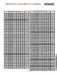
®<strong>ELECTRIC</strong><strong>HEATING</strong><strong>CATALOG</strong>Form RZ-NA-C-EH (Version
BACKGROUNDReznor was founded in 1888 to manufacture the“Reznor” reflector heater, which used a luminous flamegas burner developed by George Reznor. This technologicalbreakthrough was an immediate successand hastened the expansion of gas heating in residentialand <strong>com</strong>mercial applications. Technologicaldevelopment and innovation have been the hallmarkof Reznor products through the years. The developmentof the forced air gas unit heater, the modularThermocore ® heat exchanger, and the high-efficiency,V3 ® Series Unit Heater with the TCORE 2® single-burnerand innovative heat exchanger system, have keptReznor products at the forefront of technological advancesin <strong>com</strong>mercial and industrial gas heating. Asa result of this pioneering role in the heating, makeupair, and ventilating equipment field, the products offeredtoday are the most advanced in engineering designto satisfy a wide variety of applications.FACILITIESReznor heaters were first manufactured and sold inMercer, Pennsylvania (70 miles north of Pittsburgh)in 1888. Over the years, the <strong>com</strong>pany has grown andexpanded. Today, with sales worldwide, Reznor productsare being manufactured at facilities throughoutNorth America and Europe.PRODUCT SCOPEWell-equipped engineering laboratories for both productdevelopment and testing can be found at many ofthe manufacturing sites. All domestic lab sites areagency approved.Reznor Products include a <strong>com</strong>plete line of heating,makeup air, air conditioning and ventilating systems,using gas, oil, hot water/steam, or electric heating orcooling sources. Reznor catalogs are designed toaid the engineer, architect or contractor in specifyingthe correct equipment for all standard and special applications.Complete data is presented on unit heaters,duct furnaces, infrared heaters, makeup air systems,pre-engineered custom-designed systems,packaged cooling equipment, energy recovery andevaporative cooling modules. Consult your localReznor Sales Representative for further assistancein specifying Reznor Equipment for your specific application.SERVICESProduct service requirements are handled throughcontractors and/or distributors, with backup from localrepresentatives and factory-based service team.Replacement parts inventories for both warranty andnon-warranty requirements are maintained at servicecenters throughout the country and at the manufacturingfacilities.®
Reznor offers models for the followingapplications:• Shipping and Receiving Areas• Aircraft Hangars• Factories• Warehouses• Garages• Waste Water Treatment Plants,• Steel Mills• Construction Sites• Car Washes• Swimming Pool Areas• Sewage Treatment Plants• Petrochemical Facilities, Oil Rigs• Unattended Pumping Stations• Chemical Storage and Handling Facilities• Paint Storage Areas• Grain Elevators• Comfort Heating in Industrial Buildings• Schools• Hospitals• Department Stores• Office Complexes• Heat hoppers• Heating Trailers• Curing Plaster and Concrete• Thawing Frozen Pipes• Thawing Railroad Cars• Heating Large Tents®<strong>ELECTRIC</strong>HEATERSReznor Electric Comfort Heaters aredesigned to provide efficient, econimical,clean, fast heat for <strong>com</strong>mercial andindustrial applications. Heavy-dutyconstruction results in a long,dependable life.Electric Unit HeatersStandard Unit Heater Model EGEA........... 2Hose Down Heater Model EWH ............... 7Explosion Resistant Heater Model EXUA 10Electric Duct FurnacesModels EDI & EDF .................................. 15Infrared HeaterFixed Overhead Heater Model ERSF ..... 17Portable Heater Model ERSP ................. 17Electric Portable Blower HeaterModel EPB .............................................. 22Thermostats ................................................ 24Warranty ...................................................... 25In keeping with our policy of continuous product improvement,we reserve the right to alter, at any time, the design, construction,dimensions, weights, etc. of the equipment informationshown here.Form C-EH Page 1
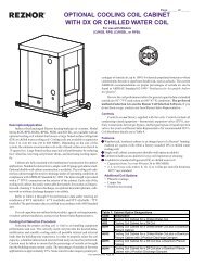
Model EGEAHorizontal or VerticalDischarge Fan ForcedUnit Heater• 2.6 - 45 kW• 8,900 - 153,000 Btuh• 208, 240, 277, 480 and 600 Volt• 1 or 3 Phase• Wall or Ceiling Mounted Configurations• CSA Certified (North America)• CE Certified (Europe) - Sizes 20 - 45OnlyDescriptionModel EGEA self-contained heater providesquiet, reliable fan-forced heating in all types of<strong>com</strong>mercial and industrial applications.Applications• Shipping and Receiving Areas• Pump Houses• Power Generating Stations• Aircraft Hangars• Factories• Warehouses• GaragesConstructionDie Formed Cabinet - Heavy gauge steel (18or 20 gauge depending on unit size), phosphateundercoated for corrosion resistance and finishedin gray polyester powder coat.Louvers - Individually adjustable louversdirect air flow up or down as needed.Finned Tubular Heating Elements have corrosionresistant steel fins that are furnace brazedto the tubular heating element to assure longlife and superior heat transfer.Fan Motor - Totally enclosed fan motor is ratedfor continuous duty with built-in thermal cutoutand operates on same voltage as the heatingcircuit.Dynamically Balanced Fan ensures smooth,quiet operation. Blade pitch is carefully selectedso that the volume of air moved results in theoptimum discharge air temperature. Fan is attachedwith rubber vibration insulators on Sizes20 - 45.FeaturesModel EGEA Sizes 2 - 15Horizontal or VerticalIntegral 24V Control Transformer - Standardon 480V and 600V models, eliminates the needfor an external control source.Heavy Duty Magnetic Contactors are standardon all models except 2.6 thru 5 kW singlephase models.Fail-Safe Linear Thermal Cutouts open thecontrol circuit and disconnect power to the heatingelements if overheating occurs. AutomaticReset allows the control circuit to reclose andrestore power when temperature returns to normal.Field Convertible - Single or three phase operationon selected sizes.Mounting Configurations• Horizontal - Recessed welded fasteners ontop of the heater cabinet are internallythreaded for suspension of unit with threadedrods. Ceiling and Universal Wall Swivel bracketsare optional. The ceiling bracket lets youmount heater directly to ceiling or overheadmember, simply and easily. The swivel mountingallows you to readily adjust the directionof warm air flow for maximum <strong>com</strong>fort up to180 degrees.• Vertical (Sizes 2 -15 Only) - Vertical DischargeRecessed fasteners on the rear of theheater cabinet are internally threaded for suspensionof unit in the vertical discharge modewith threaded rods.Subdivided Circuits with Individual Fuse Protection- Standard on all heaters with a totalcurrent draw of 48 Amps or greater. The fuse<strong>com</strong>partment is conveniently located for easyaccess.Factory Installed Options• Heat ON Indicator Light• Time Delay (heat on and off): Provides delayof fan operation until elements have warmedup. The fan stays on until cool.Model EGEA Sizes 20 - 45Horizontal onlyOptional Features (FactoryInstalled or Field InstallationKits)24V or 120V control voltage for 208/240/277 Voltunits.Summer Fan Switch Kit - Field installablefor circulating warm stratified air. Availablefor all models.Thermostat Kit - Unit-mounted, field-installableon all models. Range 40°F - 90°F.Power Disconnect Switch - Field installableswitch enables power to be disconnected whileservicing heater.• Sizes 2 - 15: 50 Amp rating mounts on thefront of the heater• Sizes 20 - 45: 40, 80 and 100 Amp modelsavailable. Mounts in the back of the heater.Mounting Brackets• Ceiling Bracket• Wall Mounting BracketAdvantages• Self Contained• Versatile, Flexible and High Performance• Easy Installation• Minimum Maintenance• Long Life• Attractive AppearanceBecause it has individually adjustable dischargelouvers to direct air flow, and can be wall orceiling (plus swivel) mounted, Model EGEA maybeusedin a variety of heating applications including:• Primary Heating• Supplementary Heating• Dual System Heating• Spot Heating• Entryway Air-Curtain HeatingC®USPage 2 Form C-EH
Model EGEASizes 2 - 15Dimensions andoptionsMounting for Horizontal Air DischargeCEILINGCEILINGAWALLBCDimensions - In. (mm)Size A B C2 - 5 16 1/8 13 10(410) (330) (254)7 - 15 20 5/8 17 1/8 12 3/4(524) (435) (324)Optional Wall Swivel Mounting Bracket - Option CK5RSPMounting LimitationsHazardous Atmosphere - Unit heaters shouldnot be used in potentially explosive atmospheres.ADAPTERBRACKETQCorrosive Atmosphere -The finish is not intendedfor direct salt spray exposure in marineapplications or the highly corrosive atmospheresof greenhouses, swimming pools, chemical storagebins, etc.TMounting Height - Do not install unit heatersabove re<strong>com</strong>mended maximum mountingheight. Obstructions must not block unit heaterair inlet or discharge.For use with P Q R S T WeightEGEA02-05EGEA07-15in. 6 1/6 18 7/8 7 5 17 5/8 lbs 3 3/4mm (157) (479) (178) (127) (448) g (1,701)in. 6 1/6 23 1/4 7 5 18 5/8 lbs 6 1/2mm (157) (591) (178) (127) (473) g (2,948)Form C-EH Page 3
Model EGEASizes 2 - 15Dimensions andOptionsOptional Ceiling Swivel Mounting Bracket - Option CK4CEILINGVC OF BOLTLCEILINGMUFOR SWIVEL MOUNTINGTO CEILING, USE ONE5/8” LAG BOLT. FOR FIXEDMOUNTING TO CEILING, USEFOUR 3/8” LAG BOLTS.AWALLBACK OF HEATERNBCWW = MINIMUM DISTANCE FROM WALL TO ALLOW FOR FULL 180° SWIVELFor use with A B C M N U V W WeightEGEA02-05EGEA07-15in. 16 1/8 13 10 8 3/8 5 3/4 7 3/4 9 3/4 12 lbs 4mm (410) (330) (254) (213) (146) (197) (248) (305) g (1,814)in. 20 5/8 17 1/8 12 3/4 10 3/4 6 3/4 7 3/4 12 12 lbs 8mm (524) (435) (324) (273) (171) (197) (305) (305) g (3,629)Hanging 3/8 - 16 Threaded Rod Spacing for Vertical Air Discharge3/8 - 1/8 THREADEDMOUNTING HOLESC LXXL2SIDE WALLC LL1TERMINAL BOXACCESS DOORBACK WALLL1 L2 Xin. 2 7/8 7 1/8 3 3/4EGEA02-05mm (73) (181) (95)in. 4 5/16 9 3/8 5 1/2EGEA07-15mm (110) (238) (140)Page 4 Form C-EH
Model EGEA Sizes 20 -45Dimensions and OptionsCeiling Mounted Heaters6”(152mm)Min.to WallKF (4) Welded fasterners 1for threaded rodJmounting tooverhead steel.IGHAWall Mounted Universal Bracket(4) 13/32” dia. wallmounting holes. 2Stop for limiting rotation.Swivel bolt permits heater to berotated to face desired direction.Four bolts are provided for fieldattachment of swivel bracket towelded fasteners on top of unit.Minimum mounting heightis 7 feet (2.15M) from floor.TRSPQ(1) 11/16” dia.swivelmountinghole.EBCeiling Mounted HeatersVUANMCD 6”(152mm)Min.W to WallWall Mounted HeatersWall Mounting Kit Option CK5EGEA P Q R S T Weight20 - 25in. 2 32 9 1/2 8 3/8 22 1/4 lbs. 7mm (51) (813) (241) (213) (565) kg (3.2)30 - 45in. 5 1/2 28 11/16 5 3 1/2 33 1/4 lbs. 10mm (140) (729) (127) (89) (845) kg (4.5)Notes —1. Threaded rod to be supplied by customer.2. Wall mounting fasteners to be supplied by customer.Ceiling Mounting Kit Option CK4EGEA A B C D E F G H I J K M N U V W Weight20 - 2530 - 45in. 24 20 1/8 11 1/2 20 1/2 16 3/4 16 8 1/4 6 6 1/4 12 10 1/16 8 6 1/4 6 7 1/4 16 lbs. 3(mm) (610) (511) (292) (521) (425) (406) (210) (152) (159) (305) (256) (203) (159) (152) (184) (406) kg (1.4)in. 24 20 1/8 17 26 16 3/4 16 8 1/4 6 11 3/4 12 10 1/16 13 3/4 9 5/16 6 7 1/4 21 lbs. 3(mm) (610) (511) (432) (660) (425) (406) (210) (152) (298) (305) (256) (349) (237) (152) (184) (533) kg (1.4)Optional Control Accessories & RemoteThermostatsFan Only Operation KitsSummer Fan Switch (OptionCH2)Thermostat Kit (OptionIC12)Optional Fan Switch KitsCH2: Unit Mounted Toggle Switch Kit for 208/240/277V units onlyCH3: Remote Swtich with Wall Plate and 24V FanRelay. For 480 or 600V units on 208/240/277V unitswith BT1 Control Transformer.Power Disconnect Kits3 Pole, 600V Rating(pictured* Rating for 480V or less is 50 Amp. Sizes 20-45 only - mounts on rear ofthe heater.** Sizes 2-15 only - mounts on front of the heater.Mounting LimitationsOptionWeightCode Rating lbs. kgCP66 40 Amp* 0.5 0.2CP67 50 Amp**CP68 80 Amp 0.5 0.2CP69 10 Amp 1 0.5Hazardous Atmosphere — Unit heaters should not be used in potentiallyexplosive atmospheres. Corrosive Atmosphere —The finishis not intended for direct salt spray exposure in marine applicationsor the highly corrosive atmospheres of greenhouses, swimming pools,chemical storage bins, etc. Mounting Height — Do not install unitheaters above re<strong>com</strong>mended maximum mounting height. Obstructionsmust not block unit heater air inlet or discharge.Form C-EH Page 5
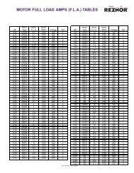
ModelEGEASpecifications andTechnical DataAFor motor data, see table.CModels can be field wired for1 or 3 phase.DIncludes motor Amps.EMaximum mounting heightfor effective heat distribution.Minimum height is 7 feet.Other Notes —1. All heaters have built-incontactors except 2.6 thru 5kW single phase models,and 480V and 600V modelshave built-in control transformersand contactors with24V holding coils. All 208and 240V 3 phase models,4kW and above, have 208/240V holding coils. All stock277V models have 277Vholding coils.2. Optional contactors holdingcoil voltages of 24V (BT1) or120V (BT2) and control voltagetransformers, are availableas made-to-ordermodels for all heater ratings.3. When total heater capacityexceeds 48 Amps, built-infusing is provided behind ahinged and latched door inthe side which allows easyaccess.Electrical (60 Hz) Motor Air DeliveryCktTemp. Horiz. Mtg. E& Rise Throw Height WeightSize kW Volts Phase Amps D Volts Phase HP RPM CFM FPM (°F) (Ft.) (Ft.) (Lbs.) (kg)2.6 208 1 - 1 13.1 208 1 1/40 1,650 410 880 21 12 8 32 152 2.6 240 1 - 1 11.4 240 1 1/40 1,650 410 880 21 12 8 32 152.6 277 1 - 1 9.6 277 1 1/30 1,550 360 770 24 12 8 32 154 208 1 - 1 19.8 208 1 1/40 1,650 410 880 31 12 8 32 154 208 1 - 3 C 11.7 208 1 1/40 1,650 410 880 31 12 8 32 154 4 240 1 - 1 17.2 240 1 1/40 1,650 410 880 31 12 8 32 154 240 1 - 3 C 10.2 240 1 1/40 1,650 410 880 31 12 8 32 154 277 1 - 1 14.6 277 1 1/30 1,550 360 770 35 12 8 32 154 480 1 - 3 5.1 480 1 1/35 1,550 380 815 33 12 8 32 155 208 1 - 1 24.6 208 1 1/40 1,650 410 880 39 12 8 32 155 208 1 - 3 C 14.5 208 1 1/40 1,650 410 880 39 12 8 32 155 5 240 1 - 1 21.4 240 1 1/40 1,650 410 880 39 12 8 32 155 240 1 - 3 C 12.6 240 1 1/40 1,650 410 880 39 12 8 32 155 277 1 - 1 18.3 277 1 1/30 1,550 360 770 44 12 8 32 155 480 1 - 3 6.3 480 1 1/35 1,550 380 815 42 12 8 32 157.5 208 1 - 1 C 36.5 208 1 1/15 1,725 850 1040 28 27 8 50 237.5 208 1 - 3 21.3 208 1 1/15 1,725 850 1040 28 27 8 50 237.5 240 1 - 1 C 31.7 240 1 1/15 1,725 850 1040 28 27 8 50 237 7.5 240 1 - 3 18.5 240 1 1/15 1,725 850 1040 28 27 8 50 237.5 277 1 - 1 27.7 277 1 1/15 1,550 750 920 32 27 8 50 237.5 480 1 - 3 9.9 480 3 1/15 1,725 850 1040 28 27 8 50 237.5 600 1 - 3 7.6 575 3 1/3 1,725 850 1040 28 27 8 50 239.7 208 1 - 1 C 47.1 208 1 1/15 1,725 850 1040 37 27 9 50 239.7 208 1 - 3 27.4 208 1 1/15 1,725 850 1040 37 27 9 50 2310 10 240 1 - 1 C 42.1 240 1 1/15 1,725 850 1040 37 27 9 50 2310 240 1 - 3 24.5 240 1 1/15 1,725 850 1040 37 27 9 50 2310 480 1 - 3 12.9 480 3 1/15 1,725 850 1040 37 27 9 50 2310 600 1 - 3 10.6 575 3 1/3 1,725 850 1040 37 27 9 50 2315 208 1 - 3 42.1 208 1 1/15 1,725 850 1040 56 27 10 50 2315 15 240 1 - 3 36.6 240 1 1/15 1,725 850 1040 56 27 10 50 2315 480 1 - 3 19.0 480 3 1/15 1,725 850 1040 56 27 10 50 2315 600 1 - 3 15.6 575 3 1/3 1,725 850 1040 56 27 10 50 2319.4 240 1 - 3 48.02 240 3 1/3 1,725 1,240 1,160 53 31 11 73 33.120 20 480 1 - 3 25 480 3 1/3 1,725 1,240 1,160 53 31 11 73 33.120 600 1 - 3 19.6 575 3 1/3 1,725 1,240 1,160 53 31 11 73 33.125 25 480 1 - 3 31 480 3 1/3 1,725 1,350 1,260 60 31 12 73 33.125 600 1 - 3 24.6 575 3 1/3 1,725 1,350 1,260 60 31 12 73 33.130 208 1 - 3 85.2 240 3 1/3 1,725 1,555 1,450 64 46 13 106 48.130 30 240 1 - 3 74.02 240 3 1/3 1,725 1,555 1,450 64 46 13 106 48.130 480 1 - 3 37.1 480 3 1/3 1,725 1,555 1,450 64 46 13 106 48.130 600 1 - 3 29.6 575 3 1/3 1,725 1,555 1,450 64 46 13 106 48.135 240 1 - 3 86.02 240 3 1/3 1,725 1,555 1,450 71 45 14 106 48.135 35 480 1 - 3 43.1 480 3 1/3 1,725 1,555 1,450 71 45 14 106 48.135 600 1 - 3 34.7 575 3 1/3 1,725 1,555 1,450 71 45 14 106 48.138 240 1 - 3 93.3 240 3 1/3 1,725 1,555 1,450 84 44 15 106 48.140 39 480 1 - 3 47.9 480 3 1/3 1,725 1,555 1,450 84 44 15 106 48.140 600 1 - 3 39.7 575 3 1/3 1,725 1,555 1,450 84 44 15 106 48.145 45 480 1 - 3 55.1 480 3 1/3 1,725 1,555 1,450 94 42 17 106 48.145 600 1 - 3 43.7 575 3 1/3 1,725 1,555 1,450 94 42 17 106 48.1Page 6 Form C-EH
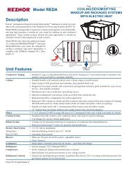
EWHHose DownCorrosionResistant BlowerHeater• 2 - 39 kWC®US• 6,800 - 133,110 Btuh• 120, 208, 240, 277, 480 and 575 Volt• 1 & 3 Phase• Built-in Controls• Vertical or Horizontal Airflow• Wall or Ceiling Mounted ConfigurationsDescriptionThis reliable, rugged, self-contained Model EWHheater is an ideal heat source for freeze protectionor <strong>com</strong>fort heat in dusty/dirty/corrosive nonhazardousenvironments. Model EWH heatersinclude low profile stainless steel wall/ceilingmounting brackets that can be used to mountdirectly to a wall for horizontal airflow perpendicularto the wall. These brackets can also beused to mount the heater directly to the ceilingfor vertical airflow.ApplicationsWaste Water Treatment Plants, Coal HandlingAreas, Food Processing Plants, Foundries, SteelMills, Cement Plants, Ships, Construction Sites,Car Washes, Swimming Pool Areas, Canneries,Hose Down (for cleaning). Corrosion Resistantfor Harsh Environments and Dairies.ConstructionRoll Formed Case is constructed of 20 gaugecorrosion resistant type 304 stainless steel.Adjustable Discharge Grille directs air flow upor down as needed.NEMA 4X Control Enclosure houses the heatercontrols, contactors and control voltage transformer,easily accessible from front of heater.Heating Elements — High quality, long-life,Stainless Steel finned tubular elements (type316) offers maximum resistance to corrosion.Totally Enclosed Motor — The motor is permanentlylubricated, ball bearing type and isepoxy painted for moisture and corrosion resistance.Dynamically Balanced Fan — Aluminum fanis epoxy coated and provides optimum air flowacross the heating elements.FeaturesTransformer provides a 120V control circuit(24V optional). Standard on all units except 2kW and 3 kW, 120V.Heavy Duty Contactors for heating circuit andmotor are included. (Not furnished on 120V, 2and 3 kW units)Automatic Reset Thermal Cutout is providedfor fast heat response and overheat protection.Fan Time Delay Relay dissipates residual heatbuildup after shutdown.Low Profile Fixed Wall & Ceiling MountingBracket (Non Swiveling)Selector Switch and"On" Indicator LightOptional Features• Integral Thermostat• 40°F to 90°F (Option IC12)• 55°F to 105°F (Option IC13)• Indicator Light• Green Indicates Power On• Selector Switch (3 position) — Heater On, Offor Fan Only Operation for Heater• Manual Reset Cutout• Epoxy Painted Stainless Steel Case• 24V Control Circuit• Field Installed Disconnect Switch• External Drip Shields• Universal Swivel Wall & Ceiling BracketField Installable Disconnect KitThe disconnect kit consists of a <strong>com</strong>plete liquidtight assembly, including a 3-pole 48 AmpSwitch, power terminal block and all the hardwareto mount to the main heater enclosure.Positive action to remove all power from enclosure.AdvantagesBecause it has an adjustable discharge grille todirect air flow, and can be wall or ceiling (plusswivel) mounted, Model EWH may be used in avariety of heating applications:• Primary Heating• Supplementary Heating• Dual System Heating• Spot Heating• Entryway Air-Curtain Heating• Freeze ProtectionForm C-EH Page 7
EWHHose DownCorrosionResistant BlowerHeater (cont’d.)CeilingCeiling Ceiling Ceiling8”(203mm)9" Min.(229mm)9" Min.(229mm)1-1/2"(38mm)12”(305mm)BWallWallWallWallC8”(203mm)A7”(178mm)8”(203mm)7”(178mm)18”(457mm)10”(254mm)FloorFloorFloorOverall Dimensions and Mounting LocationSizes Volts Phase A B C2 - 7 All 1, 3in. 13 1/2 24 1/2 15mm (343) (622) (381)10 - 2025 - 39All480, 5751, 33in. 17 1/4 28 15 1/8mm (438) (711) (384)in. 21 1/4 32 1/4 19 1/2mm (540) (819) (495)FloorPage 8 Form C-EH
EWHHose DownCorrosionResistantBlower Heater(cont’d.)Specificationsand OrderingInformationABMounting height ifmounted for horizontalairflow. For verticalmounting, minimumheight is 10'.Models can be field rewiredfor use on singlephaseElectrical (60 Hz) Motor Air DeliveryTemp. Horiz. Mtg. ARise Throw Height WeightSize kW Volts Phase Amps Volts Phase HP RPM CFM FPM (°F) (Ft.) (Ft.) (Lbs.) (kg)2 120 1 16.7 115 1 1/15 1,050 405 430 21 12 7 45 202 2 208 1 9.6 208 1 1/15 1,050 405 430 21 12 7 45 202 240 1 8.3 240 1 1/15 1,050 405 430 21 12 7 45 202 277 1 7.2 277 1 1/15 1,050 405 430 21 12 7 45 203 120 1 25 115 1 1/15 1,050 405 430 31 12 7 45 203 3 208 1 14.4 208 1 1/15 1,050 405 430 31 12 7 45 203 240 1 12.5 240 1 1/15 1,050 405 430 31 12 7 45 203 277 1 10.8 277 1 1/15 1,050 405 430 31 12 7 45 205 208 1 24 208 1 1/15 1,050 405 430 40 12 7 50 235 240 1 20.8 240 1 1/15 1,050 405 430 40 12 7 50 235 277 1 18.1 277 1 1/15 1,050 405 430 40 12 7 50 235 480 1 10.4 480 1 1/15 1,050 405 430 40 12 7 50 235 5 208 3 13.9 208 1 1/15 1,050 405 430 40 12 7 50 235 240 3 12 240 1 1/15 1,050 405 430 40 12 7 50 235 B 480 3 6 480 1 1/15 1,050 405 430 40 12 7 50 235 575 3 5 575 1 1/15 1,050 405 430 40 12 7 50 237.5 208 1 36.1 208 1 1/15 1,050 590 640 37 13 7 50 237.5 240 1 31.3 240 1 1/15 1,050 590 640 37 13 7 50 237.5 277 1 27.1 277 1 1/15 1,050 590 640 37 13 7 50 237.5 480 1 15.6 480 1 1/15 1,050 590 640 37 13 7 50 237 7.5 208 3 20.8 208 1 1/15 1,050 590 640 37 13 7 50 237.5 240 3 18.1 240 1 1/15 1,050 590 640 37 13 7 50 237.5 B 480 3 9 480 1 1/15 1,050 590 640 37 13 7 50 237.5 575 3 7.5 575 1 1/15 1,050 590 640 37 13 7 50 2310 240 1 41.7 240 1 1/15 1,050 1,180 800 28 40 7 60 2710 277 1 36.1 277 1 1/15 1,050 1,180 800 28 40 7 60 2710 480 1 20.8 480 1 1/15 1,050 1,180 800 28 40 7 60 2710 10 208 3 27.8 208 1 1/15 1,050 1,180 800 28 40 7 60 2710 240 3 24.1 240 1 1/15 1,050 1,180 800 28 40 7 60 2710 B 480 3 12 480 1 1/15 1,050 1,180 800 28 40 7 60 2710 575 3 10.1 575 1 1/15 1,050 1,180 800 28 40 7 60 2712.5 277 1 45.1 277 1 1/15 1,050 1,180 800 36 40 7 60 2712.5 480 1 26 480 1 1/15 1,050 1,180 800 36 40 7 60 2712 12.5 208 3 34.7 208 1 1/15 1,050 1,180 800 36 40 7 60 2712.5 240 3 30.1 240 1 1/15 1,050 1,180 800 36 40 7 60 2712.5 480 3 15.1 480 1 1/15 1,050 1,180 800 36 40 7 60 2712.5 575 3 12.6 575 1 1/15 1,050 1,180 800 36 40 7 60 2715 480 1 31.3 480 1 1/15 1,050 1,330 900 32 45 7 60 2715 208 3 41.7 208 1 1/15 1,050 1,330 900 32 45 7 60 2715 15 240 3 36.1 240 1 1/15 1,050 1,330 900 32 45 7 60 2715 B 480 3 18.1 480 1 1/15 1,050 1,330 900 32 45 7 60 2715 575 3 15.1 575 1 1/15 1,050 1,330 900 32 45 7 60 2719.5 240 3 47 240 1 1/15 1,050 1,330 900 42 45 7 60 2720 480 1 41.7 480 1 1/15 1,050 1,330 900 42 45 7 60 2720 20 B 480 3 24.1 480 1 1/15 1,050 1,330 900 42 45 7 60 2720 575 3 20.1 575 1 1/15 1,050 1,330 900 42 45 7 60 2725 25 480 3 30.1 480 3 1/3 1,725 2,700 1110 31 48 7 80 3625 575 3 25.1 575 3 1/3 1,550 1,800 740 42 48 7 80 3630 30 480 3 36.1 480 3 1/3 1,725 2,700 1110 37 48 7 80 3630 575 3 30.2 575 3 1/3 1,550 1,800 740 50 48 7 80 3635 35 480 3 42.1 480 3 1/3 1,725 2,700 1110 43 48 7 80 3635 575 3 35.2 575 3 1/3 1,550 1,800 740 57 48 7 80 3639 39 480 3 47 480 3 1/3 1,725 2,700 1110 50 48 7 80 3639 575 3 39.2 575 3 1/3 1,550 1,800 740 65 48 7 80 36Form C-EH Page 9
EXUAExplosion ProofBlower Heater forHazardousLocationsC®US• 3 - 35 kW• 10,200 - 119,420 Btuh• 208 to 575 Volts• 1 or 3 Phase• Meets CSA Requirements• CE Approved Models AvailableDescriptionModel EXUA is designed to heat areas classifiedas hazardous locations to provide primaryor supplementary heating for <strong>com</strong>fort or freezeprotection.Applications• Sewage Treatment Plants• Petrochemical Facilities, Oil Rigs• Unattended Pumping Stations• Chemical Storage and Handling Facilities• Paint Storage Areas• Grain Elevators• Coal Preparation Plants• Aircraft Servicing Areas• Oil Refineries• Areas Containing Metal DustsConstructionCabinet - 14 gauge steel construction with polyesterpowder coat paint finish.Adjustable Louvers - Control the direction ofairflow as needed.Rugged, Seamless, Copper Heating Elements- are immersed in the sealed liquid-to-airheat exchanger.Factory Sealed Heat Exchanger - Featuressteel tubes with integral aluminum fins and filledwith glycol-water heat transfer fluid.Safety Pressure Relief Device on the heat exchangeris factory helium leak tested to assurea leakproof design.Explosion Proof Ball Bearing Motor - Permanentlylubricated and equipped with built-in thermaloverload protection.Epoxy Coated Aluminum Fan - Prevents sparking.FeaturesPre-Wired Explosion Proof Control Centerwith magnetic contactor and control circuit transformer.Quick-acting Manual Reset CutoutPole, Wall and Ceiling Mounting Kits - Optional.Recessed threaded fasteners on top ofheater for mounting with threaded rods.Optional Features• Built-in Thermostat 50°F to 90°F• Built-in Manual Disconnect Switch• Heat "On" Indicator Light• Summer Fan SwitchDesigned for Areas ClassifiedLow operating temperature for atmosphereshaving an ignition temperature higher than165°C (329°F) code T3B.• Class I, Group C, D - Divisions 1 & 2• Class II, Groups E, F, G - Divisions 1 & 2Optional Classifications• Temperature Code T3C 160°C (320°F)- Class I, Groups C, D - Divisions 1 & 2- Class II, Groups F, G - Divisions 1 & 2• Arctic Duty ConstructionAdvantages• Easy Installation• Safe, Propylene Glycol Heat Transfer Fluid• Low Surface Temperature• Wall, Pole or Ceiling Mounting• Built-in Controls• Virtually Maintenance Free• Corrosion Resistant• 120V Control (24V optional)• Rugged and VersatilePage 10 Form C-EH
EXUAExplosion ProofBlower Heater forHazardousLocations (cont’d.)Dimensions2”(51mm)E2”(51mm)DAB11-1/16”(281mm)CMounting Kits (for units without Disconnect SwitchPost Mounting Kit (CK20)Particularly useful in buildings with insufficientstrength to use other types of mounts. Requires3-1/2" schedule 40 pipe (4" O.D.) - not supplied.Size A B A C D E (Mtg. Holes) B3 - 10in. 19 1/8 23 7/8 21 3 1/2 13 5/8mm (486) (606) (533) (89) (346)15 - 20in. 25 27 7/8 21 4 13/32 17 5/8mm (635) (708) (533) (112) (448)25 - 35in. 32 1/8 31 7/8 21 3/4 5 1/2 21 5/8mm (816) (810) (552) (140) (549)Notes —ADisconnect switch option increases B dimension by 7inches.BE dimension mounting hole center to center.Wall Mounting Kit (CK5)Ideal for use in buildings that have substantialwalls. Arm only can also be bolted directly tostructural steel. See next page for mounting unitwith Disconnect Switch.Ceiling Mounting Kit (CK4)Simple and economical if adequate overheadstructure exists. Requires 5/8" rod, cut andthreaded (not supplied).Post Mounting Bracket Wall Mounting Bracket Ceiling Mounting KitPRQSPTMounting KitsSize P Q R S T (Min.)3 - 1015 - 2025 - 35in. 10 5 1/2 29 1/2 6 7mm (254) (140) (749) (152) (178)in. 11 1/2 5 1/8 33 6 7mm (292) (130) (838) (152) (178)in. 14 1/2 6 3/8 38 1/4 6 7mm (368) (162) (972) (152) (178)RQForm C-EH Page 11
EXUAExplosion Proof Blower Heaterfor Hazardous Locations (cont’d.)Wall Mounting Kits (for models supplied with Disconnect Switch) (Option CK24)RQUTSize Q R T U Weight3 - 1015 - 2025 - 35in.in.in.7 7/813 3/414 7/831 1/1640 15/1646 1/1630 1/835 3/840 1/26 15/168 3/169 5/16LbsLbsLbs262830mmmmmm(200)(349)(378)(789)(1040)(1170)(765)(899)(1029)(176)(208)(237)kgkgkg(11.8)(12.7)(13.6)Optional Controls & DisconnectsBuilt-in Adjustable Thermostat• Temperature range 50°F to 90°F• Adjustable control knob on exterior of explosion-proofenclosure• Mounted and wired to heater control center• Eliminates installation of wall thermostatsand associated explosion-proof conduit.• Factory InstalledBuilt-in Disconnect Switch• 15, 30 or 60 Amp as required by application• Factory installed, eliminating field labor• Meets National Electric Code (NEC)Built-in Fan Switch• Allows fan only operation for coolingPage 12 Form C-EH
EXUAExplosion ProofBlower Heater forHazardous Locations(cont’d.)Specifications and Ordering InformationAir DeliveryMotor Temp. Horiz. Mtg.Electrical (60 Hz) Control Rise Throw Height WeightSize kW Volts Phase Amps Volts Phase HP RPM CFM FPM °F Ft. Ft. Lbs. (kg)3 208 1 16.7 120 or 24 1 1/4 1,725 700 900 13 28 8 135 (61.2)3 208 3 9.7 120 or 24 3 1/4 1,725 700 900 13 28 8 135 (61.2)3 3 240 1 14.8 120 or 24 1 1/4 1,725 700 900 13 28 8 135 (61.2)3 240 3 8.6 120 or 24 3 1/4 1,725 700 900 13 28 8 135 (61.2)3 480 3 4.3 120 or 24 3 1/4 1,725 700 900 13 28 8 135 (61.2)3 575 3 3.6 120 or 24 3 1/4 1,725 700 900 13 28 8 135 (61.2)5 208 1 26.3 120 or 24 1 1/4 1,725 700 900 22 28 8 135 (61.2)5 208 3 15.3 120 or 24 3 1/4 1,725 700 900 22 28 8 135 (61.2)5 5 240 1 23.1 120 or 24 1 1/4 1,725 700 900 22 28 8 135 (61.2)5 240 3 13.4 120 or 24 3 1/4 1,725 700 900 22 28 8 135 (61.2)5 480 3 6.7 120 or 24 3 1/4 1,725 700 900 22 28 8 135 (61.2)5 575 3 5.6 120 or 24 3 1/4 1,725 700 900 22 28 8 135 (61.2)7.5 208 1 38.4 120 or 24 1 1/4 1,725 840 1,070 27 32 10 135 (61.2)7.5 208 3 22.2 120 or 24 3 1/4 1,725 840 1,070 27 32 10 135 (61.2)7 7.5 240 1 33.6 120 or 24 1 1/4 1,725 840 1,070 27 32 10 135 (61.2)7.5 240 3 19.4 120 or 24 3 1/4 1,725 840 1,070 27 32 10 135 (61.2)7.5 480 3 9.7 120 or 24 3 1/4 1,725 840 1,070 27 32 10 135 (61.2)7.5 575 3 8.1 120 or 24 3 1/4 1,725 840 1,070 27 32 10 135 (61.2)10 208 3 29.2 120 or 24 3 1/4 1,725 840 1,070 36 32 10 140 (63.5)10 240 1 44 120 or 24 1 1/4 1,725 840 1,070 36 32 10 140 (63.5)10 10 240 3 25.5 120 or 24 3 1/4 1,725 840 1,070 36 32 10 140 (63.5)10 480 3 12.7 120 or 24 3 1/4 1,725 840 1,070 36 32 10 140 (63.5)10 575 3 10.6 120 or 24 3 1/4 1,725 840 1,070 36 32 10 140 (63.5)15 208 3 43 120 or 24 3 1/4 1,725 1,450 1,040 31 47 10 160 (72.6)15 15 240 3 37.5 120 or 24 3 1/4 1,725 1,450 1,040 31 47 10 160 (72.6)15 480 3 18.7 120 or 24 3 1/4 1,725 1,450 1,040 31 47 10 160 (72.6)15 575 3 15.7 120 or 24 3 1/4 1,725 1,450 1,040 31 47 10 160 (72.6)18 18 240 3 44.7 120 or 24 3 1/4 1,725 1,400 1,000 39 43 10 171 (77.6)20 20 480 3 24.8 120 or 24 3 1/4 1,725 1,400 1,000 43 43 10 171 (77.6)20 575 3 20.7 120 or 24 3 1/4 1,725 1,400 1,000 43 43 10 171 (77.6)25 25 480 3 31.1 120 or 24 3 1/2 1,725 2,330 1,070 32 54 10 216 (98.0)25 575 3 25.8 120 or 24 3 1/2 1,725 2,330 1,070 32 54 10 216 (98.0)30 30 480 3 37.1 120 or 24 3 1/2 1,725 2,330 1,070 39 54 10 216 (98.0)30 575 3 30.2 120 or 24 3 1/2 1,725 2,330 1,070 39 54 10 216 (98.0)35 35 480 3 43.1 120 or 24 3 1/2 1,725 2,330 1,070 45 54 10 216 (98.0)35 575 3 36 120 or 24 3 1/2 1,725 2,330 1,070 45 54 10 216 (98.0)Form C-EH Page 13
EXUAExplosion ProofBlower Heater forHazardous Locations(cont’d.)Heater Rating and Operating DataHazardous Location Classifications: 3 to 35 kW Models - Class I, GroupC & D; Class II, Groups E, F & G, Divisions 1 & 2Temperature Codes: This temperature shall not exceed the ignition temperatureof the gas or vapor to be encountered. All standard models 165°C(329°F) T3BINSTALLATIONMaximum Mounting Height From Floor to Bottom of Heater: 8' to 10'(2.4 to 3 meters) normal, when heat is required at floor level.Ambient Temperature: -49°F/-45°C (Min.) 104°F/40°C (Max.)Operating Limits Maximum Operational Altitude Above Sea Level:7,500 feet (2,286 meters). Check with Reznor Representative for re<strong>com</strong>mendationsfor higher elevations.PROTECTIONHigh-Limit: Manual reset quick acting linear type thermal cutout.CABINETCabinet: 14 gauge steel, polyester powder-coated. Individually adjustablelouvers with minimum position stops.Fan Guard: Heavy duty polyester powder-coated steel.Fasteners: Nickel plated steel for corrosion resistance.Conduit Material: Plated steel for corrosion resistance.Control Enclosure: Cast aluminum (non-copper Alloy) NEMA 7 and 9enclosure.Hanger Connections: 2 (two) 5/8" UNC tapped holes.CONTROLSControl Circuit: Built in 120V control. Optional 24V control available.Power Contactor: 50 Amp/600V.Transformer: Primary voltage same as heater voltage - secondary voltage,24V or 120V.Pressure Relief: Pressure relief device.HEAT EXCHANGERGeneral Description: Steel tubes, with integral rolled-aluminum finsCore Material: Steel.Heat Transfer Fluid: Propylene Glycol (Ethylene Glycol available for arcticduty - check with your Reznor Representative.)Heating Element Assembly: Immersion heater assembly with seamlesscopper sheathed heating elements.Page 14 Form C-EH
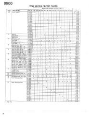
EDF & EDIFinned TubularAir Duct HeaterC®US• Up to 533 kW• Up to 35 kW/Ft 2 Power Densities• Up to 600 Volt• 6" x 8" to 40" x 120" Duct SizesModel EDI — Insert Type with IntegralControlsModel EDF — Flange Type with IntegralControlsModels EDI and EDF duct heaters are pre-engineered,factory assembled units consisting ofa standard frame section, metal sheath heatingelements and a prewired terminal box. They areavailable in a wide range of standard framesizes, with various heating capacities and heatingstages operating on AC voltage ratings of120 to 600V.The standard duct heater is designed to be insertedin a rectangular opening cut in the sideof a horizontal or vertical duct. For larger ductsor where it may be more desirable to attach theduct directly to the heater, a frame may be addedto the heater.Applications• Primary or Secondary Heating• Reheating or Preheating• Comfort Heating in Industrial Buildings,Schools, Hospitals, Department Stores,Warehouses and Office Complexes• Comfort Heating on ShipboardConstructionModel EDI — Insert Type with RemoteControlsInsert Type — DimensionsHWFeaturesModel EDF — Flange Type with RemoteControlsFlange Type — DimensionsH2” Typ.(51mm)WW = Width of Duct Heater (8 through 120 inches)H = Height of Duct Heater (6 through 40 inches)Depth of Duct Heater (6-1/2 through 36 inches)Heavy Gauge Frame of aluminized, painted orstainless steel.Terminal Box E1 General Purpose or DripProof.Finned Tubular Elements - Fast heat responding,individually replaceable finned tubular elementsprovide a long life dependable heatsource. Heavy mass of elements reduces cycletime and thermal stress. Aluminum painted orStainless Steel sheath and fin materials are available.Integral or Remote Control Panel of identicalheight as duct to ease field installation.Insert Heaters - Model EDI has frame dimensionssized so that the entire frame slidesthrough a rectangular opening in the side of theduct.Flange Heaters - Model EDF has face dimensionsthat exactly match inside duct dimensions.Heater flanges attach to matching external ductflanges in the field.Pressure Drop - Lower than tubular duct heaterssince fewer, higher watt density elementsare required.For Horizontal or Vertical upflow applications.Uniform Heat Transfer to airstream sincesheath and fins eliminate localized overheatingon elements.Clearance to Combustibles - Listed for zeroclearance to <strong>com</strong>bustible materials.Over-temperature Protection provided withboth manual and automatic resets.Factory Prewired 48 Amp maximum circuits tomeet NEC requirements.Control Options - The fan circuit must be interlockedwith the control circuit of the heater.The options are air flow switch, fan interlock relayor fan interlock relay with fan delay. Optionaldisconnecting means include the choice of nonfuseddisconnect, fused disconnect or terminalblock for remote disconnect by others.Easy Wiring access through conduit openingin terminal box.Form C-EH Page 15
Models EDF & EDIFinned TubularAir Duct Heater(cont’d.)Fan Interlock Selection - UL Standard 1096requires an acceptable means of interlocking theheater with the fan as an integral part of theheater, factory installed. One of the followingmust be used.Differential Switch - The pressure switchmethod of proving air flow is the most reliable.Minimum requirements are met when the pressurein the sensing tube, <strong>com</strong>bined velocity andstatic, is greater than the switch setting.Fan Interlock Relay - A normally open relay(contactor) is wired in series with the duct heatercontrol circuit. The coil of this relay is wired to aterminal block for field connection to the fanmotor starter circuit.Fan Interlock Relay with Fan Delay Control -Delays the fan or blower motor until after theheating elements have reached a selected temperature,eliminating the initial delivery ofunwarmed air.Standard Finned TubularElements SuppliedDuct Height Duct Depth (In.)(In.) 6.5" 12" 17-1/2"6 2 3-4 5-68 3 4-6 7-910 3-4 5-8 9-1212 6 7-12 13 - 1814 6-7 8-14 15 - 2116 6-8 9-16 17 - 2418 9 10-18 19 - 2720 9-10 1-20 21 - 3022 9-11 12-22 23 - 3324 12 13 - 24 25 - 3626 12-14 15 - 28 29 - 4228 15 16 - 30 31 - 4530 15 - 16 17 - 32 33 - 4832 15 - 17 18 - 34 35 - 5134 15 - 17 18 - 34 35 - 5136 18 19 - 36 37 - 5438 18 - 19 20 - 38 39 - 5740 18 - 20 21 - 40 41 - 60Heating Control Stages - In order to achievemodulating control of the heater, it is possibleto specify multiple heating steps or stages.Normally, the number of stages available dependsupon the number of finned tubes perheater. The number of finned tubes per heateris determined by the H dimension of the heater.Control Circuit Supply - Optional. Built-in factorywired control transformers are frequentlyrequired if a field source of control voltage isunavailable for meeting control circuit requirements.A <strong>com</strong>plete selection of transformers with primaryvoltages of 120, 208, 240, 277, 380, 480and 600V are available. Secondary voltages of24 and 120 Vac are available. Unless specified,the transformer primary voltage will be the sameas the heater line voltage.Power Disconnect Switch - Optional. To meetthe requirement for a disconnect switch at or insight of the heater, its controls and fuses; a builtindisconnect is available for power loads greaterthan 200 Amps. When this option is not selected,power terminal blocks will be provided (200Amps max per block).Horizontal Duct — Side terminal boxentry for type EDI & EDF heaters. Airflow as shown. Install with this arrow up.Configuration ERC1, AJ2Horizontal Duct — Side terminal boxentry for type EDI & EDF heaters. Airflow as shown. Install with this arrow up.Configuration ERC1, AJ1Vertical Duct — Side terminal boxentry for type EDI & EDF heaters. Airflow as shown. Install with this arrow up.Configuration ERC1, AJ3Horizontal Duct — Side terminal boxentry for type EDI & EDF heaters. Airflow as shown. Install with this arrow up.Configuration ERC2, AJ2Horizontal Duct — Side terminal boxentry for type EDI & EDF heaters. Airflow as shown. Install with this arrow up.Configuration ERC2, AJ1Vertical Duct — Side terminal boxentry for type EDI & EDF heaters. Airflow as shown. Install with this arrow up.Configuration ERC2, AJ3Page 16 Form C-EH
ModelsERSF andERSPInfra-RedRadiant Heaters1.5 kW4.5 kW4.5 kW2.0 kW6.0 kWC®US• 1.5 to 13.5 kW6.0 kW• 5,118 to 46,062 BTU/Hr• 120, 208, 240, 277, 480, and 600 V• Single or 3 Phase - Some ModelsField Convertible• Fixed Overhead - Convertible to Portable• Portable/Factory Assembled• Optional Accessories- Ground Fault- Disconnect- Tip Over Shut DownApplications• Localized heating in large plants• Loading Docks• Narrow warehouse aisle heating• Garages• Dry paint• Prevent freezing of pipes, valves• Heat hoppersDescriptionModel ERSP - PortableThe Reznor Model ERS infrared <strong>com</strong>fort heateris designed to provide a rugged source of heatfor use in areas where dependence on air movementis impractical. The heaters are versatile,designed to provide warmth directly where it isneeded for primary or spot heating applications.Each unit is constructed for long life and requiresminimal maintenance. There are no movingparts or motors to wear out, no air filters or lubricationrequired.Model ERS radiant heaters feature unique heatingelement terminal construction. This featurelowers the terminal box temperatures resultingin extended element and wiring life.Extruded aluminum housings are rigid to provideadded protection to the heating elementslocated at the focal point of a built-in mirroredaluminum reflector(s).The heater consists of hairpin bent .430” diameteralloy sheath tubular element(s) constructedof high quality resistance wire embedded in carefullyselected MgO refractory insulation. The elementfeature unique terminal construction forlonger life and cooler terminal enclosure temperatures.The element(s) also feature terminalconstruction using a waged-in silicone bushingsthat produce unequalled resistance to moistureabsorption. The heating element(s) connect toa gasketed, moisture resistance terminal enclosurewith liquid-tight bulkhead threaded fittings.An extension reflector constructed of 0.050” mirroredaluminum extends over the assembly toprovide a more uniform heating pattern.13.5 kWPortableModel ERSF - FixedModel ERSP portable heaters sizes 1.5 through4.5 are mounted on a fixed pedestal. Sizes 6and 14 are fully assembled and mounted to arugged, chrome-nickel plated tubular steel cartand handle. The cart features large wheels foreasy portability. All portable heaters includesafety grills to protect personnel from contactinghot elements.Field wiring is ac<strong>com</strong>plished through a 3/4” conduitopening in terminal enclosure. The 1.5 kWunit <strong>com</strong>es <strong>com</strong>plete with a factory installed 6foot cord and 2 prong grounding type plug. Othersizes require field supplied cable w/plug of gaugesuitable to amperage, voltage and cable length.Fixed OverheadModel ERSF fixed radiant heater is shipped fullyassembled and can be hung from the ceilingwith 2 chains or rigid angle brackets attached tothe heater brackets located on the back of theheater.Field wiring is ac<strong>com</strong>plished through the liquidtight terminal enclosure. No secondary splicebox required.Protective screens, disconnect switches andportable carts are available for these heaters.Form C-EH Page 17
Model ERSPInfra-RedRadiant Heaters(cont’d.)Portable Radiant Heaters 1.5 to 4.5 kW Dimensions11-3/4”(298mm)11-3/8”(289mm)11-3/4”(298mm)11-3/8”(289mm)28-1/2”(724mm)49”(1,245mm)Side ViewFront ViewSide View Front ViewDimensions (in.)Electrical Base BaseNo. Height Width Depth WeightSize kW Volts Phase Elem. Amps Btuh in. mm in. mm in. mm Lbs. kg1.5 1.5 120 1 1 12.5 5,118 28 1/2 (724) 11 3/8 (289) 11 3/4 (298) 15 (6.8)2.0 208 1 1 9.6 6,824 28 1/2 (724) 11 3/8 (289) 11 3/4 (298) 15 (6.8)2 2.0 240 1 1 8.3 6,824 28 1/2 (724) 11 3/8 (289) 11 3/4 (298) 15 (6.8)2.0 277 1 1 7.2 6,824 28 1/2 (724) 11 3/8 (289) 11 3/4 (298) 15 (6.8)2.0 480 1 1 4.2 6,824 28 1/2 (724) 11 3/8 (289) 11 3/4 (298) 15 (6.8)2.0 600 1 1 3.3 6,824 28 1/2 (724) 11 3/8 (289) 11 3/4 (298) 15 (6.8)4.5 208 1 1 21.6 15,354 49 (1,245) 11 3/8 (289) 11 3/4 (298) 25 (11.3)4.5 240 1 1 18.8 15,354 49 (1,245) 11 3/8 (289) 11 3/4 (298) 25 (11.3)4.5 4.5 277 1 1 16.2 15,354 49 (1,245) 11 3/8 (289) 11 3/4 (298) 25 (11.3)4.5 480 1 1 9.4 15,354 49 (1,245) 11 3/8 (289) 11 3/4 (298) 25 (11.3)4.5 600 1 1 7.5 15,354 49 (1,245) 11 3/8 (289) 11 3/4 (298) 25 (11.3)Portable Radiant Heaters 6 to 13.5 kW Dimensions19-1/4”(489mm)23-5/8”(600mm)19-1/4”(489mm)23-5/8”(600mm)32-1/2”(826mm)55-5/8”(1,413mm)Side ViewFront ViewSide ViewFront ViewDimensions (in.)Electrical Base BaseHeight Width Depth WeightSize kW Volts Phase Amps Btuh in. mm in. mm in. mm Lbs. kg6.0 208 3 16.7 20,472 32 1/2 (826) 23 5/8 (600) 11 1/2 (292) 26 (11.8)6.0 240 3 14.4 20,472 32 1/2 (826) 23 5/8 (600) 11 1/2 (292) 26 (11.8)6 6.0 277 1 21.7 20,472 32 1/2 (826) 23 5/8 (600) 11 1/2 (292) 26 (11.8)6.0 480 3 7.2 20,472 32 1/2 (826) 23 5/8 (600) 11 1/2 (292) 26 (11.8)6.0 600 3 5.8 20,472 32 1/2 (826) 23 5/8 (600) 11 1/2 (292) 26 (11.8)13.5 208 3 37.5 46,062 55 5/8 (1,413) 23 5/8 (600) 11 1/2 (292) 44 (20.0)13.5 240 3 32.5 46,062 55 5/8 (1,413) 23 5/8 (600) 11 1/2 (292) 44 (20.0)14 13.2 277 1 47.7 46,062 55 5/8 (1,413) 23 5/8 (600) 11 1/2 (292) 44 (20.0)13.5 480 3 16.3 46,062 55 5/8 (1,413) 23 5/8 (600) 11 1/2 (292) 44 (20.0)13.5 600 3 3 46,062 55 5/8 (1,413) 23 5/8 (600) 11 1/2 (292) 44 (20.0)Page 18 Form C-EH
Model ERSFInfra-RedRadiant Heaters(cont’d.)Fixed Overhead Radiant Heaters 2.0 to 4.5 kW DimensionsU.L Listed Fixed Installations2.0 kW 4.5 kW11-9/16”(294mm)11-9/16”(294mm)B15-1/2”(394mm)15-1/2”(394mm)33-1/4”(845mm)53-3/4”(1,365mm)Dimensions (in.)Electrical Base BaseHeight Width Depth WeightSize kW Volts Phase Amps Btuh in. mm in. mm in. mm Lbs. kg2.0 208 1 9.6 6,824 27 11/16 (703) 9 7/8 (251) 16 13/16 (427) 14 (6.4)2.0 240 1 8.3 6,824 27 11/16 (703) 9 7/8 (251) 16 13/16 (427) 14 (6.4)2 2.0 277 1 7.2 6,824 27 11/16 (703) 9 7/8 (251) 16 13/16 (427) 14 (6.4)2.0 480 1 4.2 6,824 27 11/16 (703) 9 7/8 (251) 16 13/16 (427) 14 (6.4)2.0 600 1 3.3 6,824 27 11/16 (703) 9 7/8 (251) 16 13/16 (427) 14 (6.4)4.5 208 1 21.6 15,354 48 3/16 (1,224) 9 7/8 (251) 16 13/16 (427) 23 (10.4)4.5 240 1 18.8 15,354 48 3/16 (1,224) 9 7/8 (251) 16 13/16 (427) 23 (10.4)4.5 4.2 277 1 16.2 15,354 48 3/16 (1,224) 9 7/8 (251) 16 13/16 (427) 23 (10.4)4.5 480 1 9.4 15,354 48 3/16 (1,224) 9 7/8 (251) 16 13/16 (427) 23 (10.4)4.5 600 1 7.5 15,354 48 3/16 (1,224) 9 7/8 (251) 16 13/16 (427) 23 (10.4)Fixed Overhead Radiant Heaters 6.0 to 13.5 kW Dimensions11-1/2”(292mm)11-1/2”(292mm)23-5/8”(600mm)23-5/8”(600mm)32-1/2”(826mm)55-5/8”(1,413mm)Dimensions (in.)Electrical Base BaseHeight Width Depth WeightSize kW Volts Phase Amps Btuh in. mm in. mm in. mm Lbs. kg6.0 208 3 16.7 20,472 32 1/2 (826) 23 5/8 (600) 11 1/2 (292) 26 (11.8)6.0 240 3 14.4 20,472 32 1/2 (826) 23 5/8 (600) 11 1/2 (292) 26 (11.8)6 6.0 277 1 21.7 20,472 32 1/2 (826) 23 5/8 (600) 11 1/2 (292) 26 (11.8)6.0 480 3 7.2 20,472 32 1/2 (826) 23 5/8 (600) 11 1/2 (292) 26 (11.8)6.0 600 3 5.8 20,472 32 1/2 (826) 23 5/8 (600) 11 1/2 (292) 26 (11.8)13.5 208 3 37.5 46,062 55 5/8 (1,413) 23 5/8 (600) 11 1/2 (292) 44 (20.0)13.5 240 3 32.5 46,062 55 5/8 (1,413) 23 5/8 (600) 11 1/2 (292) 44 (20.0)14 13.5 277 1 48.7 46,062 55 5/8 (1,413) 23 5/8 (600) 11 1/2 (292) 44 (20.0)13.5 480 3 16.3 46,062 55 5/8 (1,413) 23 5/8 (600) 11 1/2 (292) 44 (20.0)13.5 600 3 13 46,062 55 5/8 (1,413) 23 5/8 (600) 11 1/2 (292) 44 (20.0)Form C-EH Page 19
Models ERSF andERSPInfra-RedRadiant Heaters(cont’d.)AccessoriesFor use with both Fixed Overhead and PortableHeatersDisconnect Kits - Option CP70The disconnect kit consists of a <strong>com</strong>plete liquidtight assembly including a 3 pole 48 Amp switch,power terminal block and all hardware to mounteither the fixed overhead or portable radiantheater.Portable KitsTip Over Switch Kits -Option BX5Tip-over switch kits can be easily added to allModel ERSP factory assembled portable heatersor Model ERSF fixed overhead heaters whichhave been modified by use of a portable cart kit.This kit is designed to de-energize the heatingelements of unattended units in event the heateris accidentally knocked over. The kit includes acontrol circuit transformer, magnetic contactor,tip-over switch assembly and on-off toggle switchwith rubber boot, <strong>com</strong>pletely prewired in a NEMA4 enclosure. The kit also includes a 1” coupling,wiring between the contactor and heater, mountingbracket, hardware and instructions to <strong>com</strong>-Heater WeightPart No. Volts Lbs kg215936 208 14 (6.4)215937 240 14 (6.4)215938 277 14 (6.4)215939 480 14 (6.4)215940 600 14 (6.4)Tip-Over Switch and Ground Fault Detector Kits - Option BF18(for portable Model ERSP6 and 14 Heaters)The ground fault detector kit includes the <strong>com</strong>ponents and features of the tip-over kit with theadditional protection provided by a ground fault detector. The ground fault detector will monitor forany gradual changes in the insulation level due to humidity or mechanical damage as they developand will de-energize the contactor to prevent arcing type faults, preventing premature elementHeater WeightPart No. Volts Lbs. kg215941 208 16 (7.3)215942 240 16 (7.3)215943 277 16 (7.3)215944 480 16 (7.3)215945 600 16 (7.3)Page 20 Form C-EH
Model ERSInfra-RedRadiant Heaters(cont’d.)Accessories for Fixed Overhead HeatersHanger Kit - Option UE4Hanger kits include 24 feet of chain, 4 “S” hooks to mount units in a fixed overhead position usingthe universal mounting brackets included on the back of fixed overhead radiant models. The chainis long enough to allow all heaters to be mounted up to 6 feet from the ceiling.Portable Cart Kits - Option UK2Model ERSF fixed overhead radiant heaters in sizes 6 and 14 can be field converted to portablespot heaters with the use of the cart kits. Each kit includes wheels, legs, handle, grill(s), baffle (ifrequired) and all of the necessary hardware to <strong>com</strong>plete the modification. These kits are easy toinstall with standard tools.WeightPart No. kW Lbs. kg215946 6 8 (3.6)215947 13.5 8 (3.6)Safety Grill Kits - Option DN3The safety grill kits contain one (2kW, 4.5kW and 6kW) or two grills (13.5kw) to protect personnelfrom <strong>com</strong>ing in contact with hot heating elements. The grills are constructed of heavy gauge platedsteel and are simple to install.WeightPart No. Size Lbs. kg215948 2 5 (2.3)215949 4.5 5 (2.3)215950 6 6 (2.7)215951 14 12 (5.4)Ground Fault Detection - Option BF17Wall mounted ground fault detectors are designed to monitor for any gradual changes in the insulationlevel due to humidity or mechanical damage as they develop and will de-energize the load toprevent arcing type faults, preventing premature element failure and potential fire damage. Thedetector consists of a ground fault sensor, control circuit transformer, magnetic contactor and anon off toggle switch with rubber boot, <strong>com</strong>pletely pre-wired in a NEMA 4 enclosure.Replacement ElementsHeater WeightPart No. Volts Lbs. kg21952 208 16 (7.3)21953 240 16 (7.3)21954 277 16 (7.3)21955 480 16 (7.3)21956 600 16 (7.3)Dimensions - inchesPart A B WeightNumber kW Volts Win2 in. mm in. mm Lbs. kg215957 1.5 120 32 21 1/2 (546) 20 1/2 (521) 2 (0.9)215958 2 208 42 21 1/2 (546) 20 1/2 (521) 3 (1.4)215959 2 240 42 21 1/2 (546) 20 1/2 (521) 3 (1.4)215960 2 277 42 21 1/2 (546) 20 1/2 (521) 3 (1.4)215961 2 480 42 21 1/2 (546) 20 1/2 (521) 3 (1.4)215962 2 600 42 21 1/2 (546) 20 1/2 (521) 3 (1.4)215963 4.5 208 42 43 3/8 (1,102) 42 3/8 (1,076) 4 (1.8)215964 4.5 240 42 43 3/8 (1,102) 42 3/8 (1,076) 4 (1.8)215965 4.5 277 42 43 3/8 (1,102) 42 3/8 (1,076) 4 (1.8)215966 4.5 480 42 43 3/8 (1,102) 42 3/8 (1,076) 4 (1.8)215967 4.5 600 42 43 3/8 (1,102) 42 3/8 (1,076) 4 (1.8)A ±1/4B0.609”RForm C-EH Page 21
EPBPortable Spot IndustrialBlower Heater• 7.5 to 30 kW• 25,590 to 102,360 BTUH• 208, 240, 480 and 600 Volts• Single and Three Phase• No Assembly RequiredC®US• Built-in ControlsDimensions (Inches)16-1/2”(419mm)I.D.20-9/16”(522mm)DescriptionHandle FullyExtended34-1/4”(870mm)18-1/2”(470mm)O.D.Model EPB is a rugged industrial grade, self contained,highly mobile, electric blower heater.Model EPB can be left unattended without thethreat of poisoning from <strong>com</strong>bustion by-productsassociated with fuel fired heaters. The builtin safety features include an adjustable thermostatto control the outlet air temperature, autoresetcutouts for the fan motor and heatingelements. The thermostat provides settings forfull off, fan only and temperature control in theheating setting. Model EPB heaters feature alarge, easily accessible control and wiring <strong>com</strong>partmentcontaining a magnetic contactor; additionalsafety is provided by a 120 volt controlvoltage transformer and motor starter on 480and 600 volt units. The bright red polyester powdercoated heating cylinder is highly visible andcan be rotated to direct heat or fan driven airmovement where it is needed. For assuredsafety, all standard units meet the requirementsof CSA (File No. LR40859).ConstructionHeating Cylinder - A structural frame consistingof 2 spun steel rings and 2 formed steelchannels support a 20 gauge steel cylinderphosphate coated for corrosion resistance, andfinished in red polyester powder coat paint. Theheating cylinder pivots vertically to direct air flow.Leg Assembly - Each side consists of a onepiece, 12 gauge, formed steel member, whichaccepts a steel tubular handle, held in place witha 1 1/2" long x 1/4" bolt on each side. The handlecan be raised from the shipping position if desired.The rubber, pneumatic wheels are 10"diameter and 3 1/2” wide to provide ease oftransporting the heater on irregular and gravelsurfaces. The large wheels make it easy to rollup stairways without damage to decorative stepsurfaces.27-11/16”(703mm)Fan Assembly - The self-centering fan assemblyconsists of a totally enclosed, permanentlylubricated motor and a dynamically balancedaluminum fan blade for smooth, quiet operation.Controls - A thermostat, with a temperaturerangeof40°F to 100°F is included, with a full off position,a fan only position and an adjustable rangeof temperature settings in the heating modeposition. Each unit includes a 3 pole magneticcontactor and auto-reset thermal cutout. 480volt and 600 volt units also include a motor relayand 120 volt control voltage transformer forpersonnel safety.Safety Guards - Front and rear grills are 10gauge, finished in black polyester powder coatand are designed to meet OSHA safety requirements.Heating Assembly - The patented metal sheathfinned tubular heating elements consist of steelfins furnace brazed on industrial grade .475 diametersteel sheath tubular heaters for maximumheat transfer. The elements are held inplace with steel bulkhead fittings for durability.The elements feature a high temperature finishfor corrosive protection.23-7/16”(595mm)Applications• For Best Results Use in Enclosed Area withCeiling Heights Below 15 feet• Any Commercial or Industrial ApplicationNeeding Instant Fan Forced Heat• Heating Trailers• Building Construction• Curing Plaster and Concrete• Warming Workers• Thawing Frozen Pipes• Thawing Railroad Cars• Heating Large Tents• Non-Hazardous AreasPage 22 Form C-EH
EPBPortable Spot IndustrialBlower Heater (cont’d.)Specifications And Ordering InformationTemp. WeightSize kW Volts Phase Amps A BTU/H HP CFM Rise °F B Lbs. kg7 7.5 208 1 and 3 36.3/21.0 25,590 0.06 1070 23 65 (29.5)7.5/5.6 240/208 1 and 3 31.5/18.3 C 25,590 0.06 1070 23 65 (29.5)10 9.75 208 1 and 3 47.1/27.3 33,267 0.06 1070 31 65 (29.5)10/7.5 240/208 1 and 3 40.8/23.7 C 33,267 0.06 1070 31 65 (29.5)15 208 3 41.8 51,180 0.06 1070 46 65 (29.5)15 15/11.2 240/208 3 36.3 C 51,180 0.06 1070 46 65 (29.5)15 480 1 and 3 31.4/18.2 51,180 0.06 1070 46 65 (29.5)15 600 1 and 3 25.2/14.6 51,180 0.06 1070 46 65 (29.5)19.5/15 240/208 3 47.1 C 66,534 0.06 1070 61 75 (34.0)20 20 480 1 and 3 42.0/24.4 68,240 0.06 1070 62 75 (34.0)20 600 1 and 3 33.5/19.4 68,240 0.06 1070 62 75 (34.0)30 30 480 3 36.3 102,360 0.06 1070 92 75 (34.0)30 600 3 29.1 102,360 0.06 1070 92 75 (34.0)ABCIncludes motor ampsTemperature rise at 240V operation208V amperage is 86% of 240V valueForm C-EH Page 23
Option CL5A & CL5BThermostatsOption CL1AWall Mounted Residential & Commercial RoomThermostat• 22 Amps, 120 Vac - 240 Vac 18 Amps, 277 Vac• 45 - 75°F Temperature Range• Ivory Color• Mounts in Standard Electrical BoxDescriptionOption CL5A & CL5B RoomThermostats are designed tocontrol individual heaters or maybe used with an external contactor.Option CL5A provides heatcontrol with a SPST snap actionswitch (open on rise) for breakingone line of the power source.Option CL5B also is a heat controlbut uses a DPST snap actionswitch and will break bothlines of the power source.Both models include heat anticipators—assuringcloser andmore even temperature regulation.WARNING: Hazard of Fire.Thermostats are designed fortemperature control service only.Because they are not fail-safe,they should not be used for temperature limiting duty.Wall Mounted Residential &Commercial Room Thermostat• 24 - 30 Vac, 1A Maximum• 40 - 80°F Temperature Range• Beige Color• Mounts in Standard Electrical Box• Screw Terminals for Signal WiringDescriptionOption CL1A Room Thermostatis designed for space heaterswith low voltage control circuits.Its operation is from a sealedmercury cell providing long lifeand protection from environmentaldirt and moisture. Theheating anticipator provides anarrow differential control ofroom temperature, 1°F.WARNING: Hazard of Fire.Thermostat is designed fortemperature control serviceonly. Because it is not fail-safe,it should not be used for temperaturelimiting duty.2-7/8”(73mm)2-1/8”(54mm) 2-3/4”(70mm)1-1/2”(38mm)4-3/4”(120mm)4-3/4”(121mm)Front Side Front SideTemp. Voltage/Current Wt.Option Type Range (°F) 120V 208V 240V 277V (Lbs.)CL5A SPST 45-75 22A 22A 22A 18A 1CL5B DPST 45-75 22A 22A 22A 18A 1Page 24 Form C-EHVoltageTemp. Current Wt.Model Type Range (°F) 24-30 Vac (Lbs.)SPST Low VoltCL1A(opens on rise)40 - 80 1A Max. 1
LIMITED PRODUCT WARRANTYThomas & Betts Corporation warrants to the original owner-user that this Reznor product will be free fromdefects in material or workmanship. This warranty is limited to twelve (12) months from the date of originalinstallation, whether or not actual use begins on that date, or eighteen (18) months from date of shipment byThomas & Betts Corporation, whichever occurs first.LIMITATIONS AND EXCLUSIONSThomas & Betts Corporation’s obligations under this warranty and the sole remedy for its breach are limitedto repair, at its manufacturing facility, of any part or parts of its Reznor products which prove to be defective;or, in its sole discretion, replacement of such products. All returns of defective parts or products must includethe product model number and serial number, and must be made through an authorized Reznor distributoror arranged through Reznor Customer Service. Authorized returns must be shipped prepaid. Repaired orreplacement parts will be shipped by Thomas & Betts F.O.B. shipping point.1. The warranty provided herein does not cover charges for labor or other costs incurred in the troubleshooting, repair,removal, installation, service or handling of parts or <strong>com</strong>plete products.2. All claims under the warranty provided herein must be made within ninety (90) days from the date of discovery of thedefect. Failure to notify Thomas & Betts of a warranted defect within ninety (90) days of its discovery voids Thomas &Betts's obligations hereunder.3. The warranty provided herein shall be void and of no effect in the event that (a) the product has been operated outsideits designed output capacity (heating, cooling, airflow); (b) the product has been subjected to misuse, neglect, accident,improper or inadequate maintenance, corrosive environments, environments containing airborne contaminants(silicone, aluminum oxide, etc.), or excessive thermal shock; (c) unauthorized modifications are made to the product;(d) the product is not installed or operated in <strong>com</strong>pliance with the manufacturer’s printed instructions; (e) the productis not installed and operated in <strong>com</strong>pliance with applicable building, mechanical, plumbing and electrical codes; or (f)the serial number of the product has been altered, defaced or removed.4. The warranty provided herein is for repair or replacement only. Thomas & Betts Corporation shall not be liable for anyloss, cost, damage, or expense of any kind arising out of a breach of the warranty. Further, Thomas & Betts Corporationshall not be liable for any incidental, consequential, exemplary, special, or punitive damages, nor for any loss ofrevenue, profit or use, arising out of a breach of this warranty or in connection with the sale, maintenance, use,operation or repair of any Reznor product. In no event will Thomas & Betts be liable for any amount greater than thepurchase price of a defective product. The disclaimers of liability included in this paragraph 4 shall remain in effectand shall continue to be enforceable in the event that any remedy herein shall fail of its essential purpose.5. THIS WARRANTY IS THE SOLE AND EXCLUSIVE WARRANTY FOR REZNOR PRODUCTS, AND IS IN LIEU OFALL OTHER EXPRESS AND IMPLIED WARRANTIES. THOMAS & BETTS CORPORATION SPECIFICALLY DIS-CLAIMS ALL OTHER EXPRESS AND IMPLIED WARRANTIES, INCLUDING, BUT NOT LIMITED TO, ALL IMPLIEDWARRANTIES OF MERCHANTABILITY AND FITNESS FOR A PARTICULAR PURPOSE. No person or entity isauthorized to bind Thomas & Betts Corporation to any other warranty, obligation or liability for any Reznor product.Installation, operation or use of the Reznor product for which this warranty is issued shall constitute acceptance of theterms hereof.Form C-EH Page 25
Reznor ® is your global source for heating,ventilating and air conditioning equipment.Global HeadquartersManufacturing or Warehouse FacilityCorporate Sales OfficeRepresentative Sales Office®For more information on Reznor HVAC Equipment,contact your local Reznor Representative by calling800-695-1901.Or, find us on the internet atwww.RezSpec.<strong>com</strong>Reznor is registered in at least the United States. All other marks are the property of their respective organizations.© 2006 Thomas & Betts Corporation. All rights reserved. Printed in U.S.A.1206 OG POD Form RZ-NA-C-EH (Version B.3)