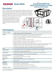
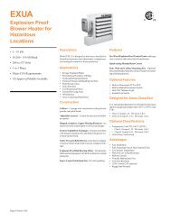
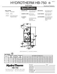
EXUAExplosion Proof Blower Heaterfor Hazardous Locations (cont’d.)Wall Mounting Kits (for models supplied with Disconnect Switch) (Option CK24)RQUTSize Q R T U Weight3 - 1015 - 2025 - 35in.in.in.7 7/813 3/414 7/831 1/1640 15/1646 1/1630 1/835 3/840 1/26 15/168 3/169 5/16LbsLbsLbs262830mmmmmm(200)(349)(378)(789)(1040)(1170)(765)(899)(1029)(176)(208)(237)kgkgkg(11.8)(12.7)(13.6)Optional Controls & DisconnectsBuilt-in Adjustable Thermostat• Temperature range 50°F to 90°F• Adjustable control knob on exterior of explosion-proofenclosure• Mounted and wired to heater control center• Eliminates installation of wall thermostatsand associated explosion-proof conduit.• Factory InstalledBuilt-in Disconnect Switch• 15, 30 or 60 Amp as required by application• Factory installed, eliminating field labor• Meets National Electric Code (NEC)Built-in Fan Switch• Allows fan only operation for coolingPage 12 Form C-EH
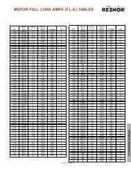
EXUAExplosion ProofBlower Heater forHazardous Locations(cont’d.)Specifications and Ordering InformationAir DeliveryMotor Temp. Horiz. Mtg.Electrical (60 Hz) Control Rise Throw Height WeightSize kW Volts Phase Amps Volts Phase HP RPM CFM FPM °F Ft. Ft. Lbs. (kg)3 208 1 16.7 120 or 24 1 1/4 1,725 700 900 13 28 8 135 (61.2)3 208 3 9.7 120 or 24 3 1/4 1,725 700 900 13 28 8 135 (61.2)3 3 240 1 14.8 120 or 24 1 1/4 1,725 700 900 13 28 8 135 (61.2)3 240 3 8.6 120 or 24 3 1/4 1,725 700 900 13 28 8 135 (61.2)3 480 3 4.3 120 or 24 3 1/4 1,725 700 900 13 28 8 135 (61.2)3 575 3 3.6 120 or 24 3 1/4 1,725 700 900 13 28 8 135 (61.2)5 208 1 26.3 120 or 24 1 1/4 1,725 700 900 22 28 8 135 (61.2)5 208 3 15.3 120 or 24 3 1/4 1,725 700 900 22 28 8 135 (61.2)5 5 240 1 23.1 120 or 24 1 1/4 1,725 700 900 22 28 8 135 (61.2)5 240 3 13.4 120 or 24 3 1/4 1,725 700 900 22 28 8 135 (61.2)5 480 3 6.7 120 or 24 3 1/4 1,725 700 900 22 28 8 135 (61.2)5 575 3 5.6 120 or 24 3 1/4 1,725 700 900 22 28 8 135 (61.2)7.5 208 1 38.4 120 or 24 1 1/4 1,725 840 1,070 27 32 10 135 (61.2)7.5 208 3 22.2 120 or 24 3 1/4 1,725 840 1,070 27 32 10 135 (61.2)7 7.5 240 1 33.6 120 or 24 1 1/4 1,725 840 1,070 27 32 10 135 (61.2)7.5 240 3 19.4 120 or 24 3 1/4 1,725 840 1,070 27 32 10 135 (61.2)7.5 480 3 9.7 120 or 24 3 1/4 1,725 840 1,070 27 32 10 135 (61.2)7.5 575 3 8.1 120 or 24 3 1/4 1,725 840 1,070 27 32 10 135 (61.2)10 208 3 29.2 120 or 24 3 1/4 1,725 840 1,070 36 32 10 140 (63.5)10 240 1 44 120 or 24 1 1/4 1,725 840 1,070 36 32 10 140 (63.5)10 10 240 3 25.5 120 or 24 3 1/4 1,725 840 1,070 36 32 10 140 (63.5)10 480 3 12.7 120 or 24 3 1/4 1,725 840 1,070 36 32 10 140 (63.5)10 575 3 10.6 120 or 24 3 1/4 1,725 840 1,070 36 32 10 140 (63.5)15 208 3 43 120 or 24 3 1/4 1,725 1,450 1,040 31 47 10 160 (72.6)15 15 240 3 37.5 120 or 24 3 1/4 1,725 1,450 1,040 31 47 10 160 (72.6)15 480 3 18.7 120 or 24 3 1/4 1,725 1,450 1,040 31 47 10 160 (72.6)15 575 3 15.7 120 or 24 3 1/4 1,725 1,450 1,040 31 47 10 160 (72.6)18 18 240 3 44.7 120 or 24 3 1/4 1,725 1,400 1,000 39 43 10 171 (77.6)20 20 480 3 24.8 120 or 24 3 1/4 1,725 1,400 1,000 43 43 10 171 (77.6)20 575 3 20.7 120 or 24 3 1/4 1,725 1,400 1,000 43 43 10 171 (77.6)25 25 480 3 31.1 120 or 24 3 1/2 1,725 2,330 1,070 32 54 10 216 (98.0)25 575 3 25.8 120 or 24 3 1/2 1,725 2,330 1,070 32 54 10 216 (98.0)30 30 480 3 37.1 120 or 24 3 1/2 1,725 2,330 1,070 39 54 10 216 (98.0)30 575 3 30.2 120 or 24 3 1/2 1,725 2,330 1,070 39 54 10 216 (98.0)35 35 480 3 43.1 120 or 24 3 1/2 1,725 2,330 1,070 45 54 10 216 (98.0)35 575 3 36 120 or 24 3 1/2 1,725 2,330 1,070 45 54 10 216 (98.0)Form C-EH Page 13