kn series gas boiler installation & operating ... - Agencespl.com
kn series gas boiler installation & operating ... - Agencespl.com
kn series gas boiler installation & operating ... - Agencespl.com

You also want an ePaper? Increase the reach of your titles
YUMPU automatically turns print PDFs into web optimized ePapers that Google loves.
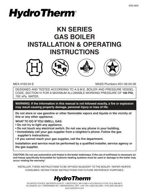
KN2-805KN SERIESGAS BOILERINSTALLATION & OPERATINGINSTRUCTIONSMEA #163-04-EMASS Plumbers #G1-06-04-28DESIGNED AND TESTED ACCORDING TO A.S.M.E. BOILER AND PRESSURE VESSELCODE, SECTION IV FOR A MAXIMUM ALLOWABLE WORKING PRESSURE OF 100 PSI,700 kPa, WATER.WARNING: If the information in this manual is not followed exactly, a fire or explosionmay result causing property damage, personal injury or loss of life.Do not store or use <strong>gas</strong>oline or other flammable vapors and liquids in the vicinity ofthis or any other appliance.WHAT TO DO IF YOU SMELL GAS:• Do not try to light any appliance.• Do not touch any electrical switch. Do not use any phone in your building.• Immediately call your <strong>gas</strong> supplier from a neighbor’s phone. Follow the <strong>gas</strong>supplier’s instructions.• If you cannot reach your <strong>gas</strong> supplier, call the fire department.Installation and service must be performed by a qualified installer, service agency orthe <strong>gas</strong> supplier.CAUTION: Do not use automotive anti-freeze in the <strong>boiler</strong> waterways. If the use of antifreeze is necessary ananti-freeze specifically formulated for hydronic heating systems must be used or damage to the <strong>boiler</strong> mayoccur voiding the warranty!INSTALLER, THESE INSTRUCTIONS TO BE AFFIXED ADJACENT TO THE BOILER / WATER HEATER.CONSUMER, RETAIN THESE INSTRUCTIONS FOR FUTURE REFERENCE PURPOSES.IN UNITED STATES: 260 NORTH ELM ST. • WESTFIELD, MA 01085 • (413) 564-5515 • FAX (413) 568-9613IN CANADA: 5211 CREEKBANK RD. • MISSISSAUGA, ONT. L4W 1R3 • (905) 625-2991 • FAX (905) 625-6610www.hydrotherm.<strong>com</strong>
Page 2KN INSTALLATION AND OPERATION INSTRUCTIONSAVERTISSMENT. Assurez-vous de bien suivre les instructions données dans cettenotice pour réduire au minimum le risque d’incendie ou d’explosion ou pour évitertout dommoge matériel, toute blessure ou la mortNe pas entreposer ni utiliser d’essence ou ni d’autres vapeurs ou liquides inflammablesà proximité de cet appareil ou de tout autre appareil.QUE FAIRE SI VOUS SENTEZ UNE ODEUR DE GAZ:• Ne pas tenter d’allumer d’appareil.• Ne touchez à aucun interrupteur; ne pas vous servir des téléphones se trouvant dansle bâtiment.• Appelez immédiatement votre fournisseur de <strong>gas</strong> depuis un voisin. Suivez lesintructions du fournisseur.• Si vous ne purvez rejoindre le fournisseur, appelez le service des incendies.L’<strong>installation</strong> et l’entretien doivent être assurés par un installateur ou un serviced’entretien qualifié ou par le fournisseur de gaz.CONTENTSBefore Your Start ................................................page 2Ratings & Capacities .......................................... page 3Location..............................................................page 3Combustion Air & Ventilation .............................. page 3Venting Guidelines .............................................page 5Common Vent Systems ....................................page 12General Piping Requirements ..........................page 13Heating System Piping .....................................page 13Domestic Water Supply Piping .........................page 16Condensate Piping ...........................................page 17Gas Supply Piping............................................page 17Electrical Wiring ...............................................page 18Boiler Operation ...............................................page 18Operating Instructions ......................................page 19Sequence of Operation ....................................page 21Checking & Adjustment ....................................page 22Diagnostics.......................................................page 23Maintenance.....................................................page 24Troubleshooting ................................................page 25Repair Parts .....................................................page 26Wiring ........................................................pages 29-32BEFORE YOU STARTThis manual covers the application, <strong>installation</strong>,operation and maintenance of a KN <strong>series</strong> <strong>boiler</strong>.To obtain the safe, dependable, efficient operation andlong life for which this <strong>boiler</strong> was designed, theseinstructions must be read, understood and followed.The KN <strong>boiler</strong> <strong>series</strong> has been design certified by CSAfor use with natural and propane <strong>gas</strong> under the latestrevision of ANSI-Z21.13/CSA 4.9, Gas-Fired LowPressure Steam and Hot Water Boilers and CAN1-3.1,Industrial and Commercial Gas Fired Packaged Boilers.Each unit has been constructed and hydrostaticallytested for a maximum working pressure of 100 psi,700 kPa, in accordance with Section IV of the A.S.M.E.Boiler and Pressure Vessel Code.All aspects of the <strong>boiler</strong> <strong>installation</strong> must conform to therequirements of the authority having jurisdiction, or, inthe absence of such requirements, to the National FuelGas Code, ANSI Z223.1/NFPA 54-latest revision. Whererequired by the authority having jurisdiction, the<strong>installation</strong> must conform to the Standard for Controlsand Safety Devices for Automatically Fired Boilers,ANSI/ASME CSD-1.If installed in the Commonwealth of Massachusetts, youMUST FOLLOW the additional instructions contained inHydroTherm’s instruction sheet MACODE-1. If you don’thave a copy call your HydroTherm distributor orHydroTherm.In Canada, the <strong>installation</strong> must be in accordance withthe requirements of CSA B149.1 or .2, Installation Codefor Gas Burning Appliances and Equipment.The owner should maintain a record of all service workperformed with the date and a description of the workdone. Include the name of the service organization forfuture reference.Direct all questions to your HydroTherm distributor orcontact the HydroTherm Customer Service Departmentat: 260 North Elm Street, Westfield, MA 01085. Alwaysinclude the model and serial numbers from the ratingplate of the <strong>boiler</strong> in question.
KN INSTALLATION AND OPERATION INSTRUCTIONSPage 3RATINGS & CAPACITIESBefore installing the KN <strong>boiler</strong> check the rating plate toensure that the unit has been sized properly for the job.Also ensure that the unit has been set up for the typeof <strong>gas</strong> available at the <strong>installation</strong> site. Other importantconsiderations are the availability of an adequateelectrical supply, fresh air for <strong>com</strong>bustion and a suitablechimney or vent system.BOILER LOCATION1. This <strong>boiler</strong> is suitable for indoor <strong>installation</strong>s only.Locate the <strong>boiler</strong> in an area that provides goodaccess to the unit. Servicing may require theremoval of jacket panels. Allow the minimumclearances between adjacent construction and the<strong>boiler</strong> as listed in Table 1.NOTE: Service clearances are not mandatory, butare re<strong>com</strong>mended to ensure ease of service shouldit be required.Table 1 - ClearancesClearance to ServiceCombustibles Clearancein mm in mmTop 6 153 24 610Back 6 153 24 610Left Side 6 153 24 610Right Side 6 153 24 610Front 6 153 36 914Flue 6 1532. An optimum site will be level, central to the pipingsystem, close to a chimney or outside wall and haveadequate fresh air for <strong>com</strong>bustion. Ensure that theunit is level from front to back and from side to side.Use metal shims if leveling is required. Electrical andelectronic <strong>com</strong>ponents must be protected fromexposure to water during operation and maintenance.DO NOT install this <strong>boiler</strong> in a location that wouldsubject any of the <strong>gas</strong> ignition and other electronic<strong>com</strong>ponents to direct contact with water or excessivemoisture during operation or servicing.3. Ensure that the floor is structurally sound and willsupport the weight of the <strong>boiler</strong>.NOTE: The KN may be installed directly on<strong>com</strong>bustible flooring, but never on carpeting.4. Locate the <strong>boiler</strong> in an area that will prevent waterdamage to adjacent construction should a leakoccur or during routine maintenance.5. DO NOT place this <strong>boiler</strong> in a location that wouldrestrict the introduction of <strong>com</strong>bustion air into theunit or subject it to a negative pressure unless the<strong>com</strong>bustion air is piped from the outside, see theCOMBUSTION AIR & VENTILATION section.6. NEVER place this <strong>boiler</strong> in a location that wouldsubject it to temperatures at or near freezing. Seethe FREEZE PROTECTION SECTION on page 7.WARNING: Never store <strong>com</strong>bustible materials,<strong>gas</strong>oline or any product containing flammablevapors or liquids in the vicinity of the <strong>boiler</strong>.Failure to <strong>com</strong>ply with this warning can resultin an explosion or fire causing extensiveproperty damage, severe personal injury ordeath!COMBUSTION AIR & VENTILATIONWARNING: This <strong>boiler</strong> must be supplied with<strong>com</strong>bustion air in accordance with Section 5.3,Air for Combustion & Ventilation, of the latestrevision of the National Fuel Gas Code, ANSIZ223.1/NFPA 54 and all applicable local buildingcodes. Canadian <strong>installation</strong>s must <strong>com</strong>ply withCSA B149.1 or .2 Installation Code for GasBurning Appliances and Equipment, orapplicable provisions of the local building codes.Failure to provide adequate <strong>com</strong>bustion air forthis <strong>boiler</strong>/water heater can result in excessivelevels of carbon monoxide which can result insevere personal injury or death!To operate properly and safely this <strong>boiler</strong> requires acontinuous supply of air for <strong>com</strong>bustion. NEVER storeobjects on or around the <strong>boiler</strong>!CAUTION: Combustion air contaminated with fluorocarbonsor other halogenated <strong>com</strong>pounds such ascleaning solvents and refrigerants will result in theformation of acids in the <strong>com</strong>bustion chamber.These acids will cause premature failure of the<strong>boiler</strong> voiding the warranty!CAUTION: If the <strong>boiler</strong> is operated while the buildingis under construction it must be protected fromwood, concrete, sheet rock and other types ofdust. Failure to properly protect the unit fromconstruction dust will damage the unit voiding thewarranty!
Page 4KN INSTALLATION AND OPERATION INSTRUCTIONSBuildings will require the <strong>installation</strong> of a fresh air ductor other means of providing make-up air if the intakeair option isn't used. Any building utilizing other <strong>gas</strong>burning appliances, a fireplace, wood stove or any typeof exhaust fan must be checked for adequate<strong>com</strong>bustion air when all of these devices are inoperation at one time. Sizing of an outside air duct mustbe done to meet the requirements of all such devices.WARNING: Never operate the KN-10 in anenvironment subjected to a negative pressureunless it is Direct Vented. Failure to <strong>com</strong>ply withthis warning can result in excessive levels ofcarbon monoxide causing severe personalinjury or death!All Air From Inside The BuildingIf the <strong>boiler</strong> is to be located in a confined space theminimum clearances listed in Table 1 must bemaintained between it and any <strong>com</strong>bustible construction.When installed in a confined space without the intakeair option two permanent openings <strong>com</strong>municating withan additional room(s) are required. The <strong>com</strong>binedvolume of these spaces must have sufficient volume tomeet the criteria for an unconfined space. The total airrequirements of all <strong>gas</strong> utilization equipment, fireplaces,wood stoves or any type of exhaust fan must beconsidered when making this determination. Eachopening must have a minimum free area of 1 in 2 /1000Btu/hr, 2200 mm 2 /kW based on the total input rating ofALL <strong>gas</strong> utilization equipment in the confined area. Eachopening must be no less than 100 in 2 , 64,516 mm 2 insize. The upper opening must be within 12 in, 300 mmof, but not less than 3 in, 80 mm from, the top of theenclosure. The bottom opening must be within 12 in,300 mm of, but not less than 3 in, 80 mm from, thebottom of the enclosure.All Air From Outside The BuildingWhen installed in a confined space without the intakeair option two permanent openings <strong>com</strong>municatingdirectly with, or by ducts to, the outdoors or spaces thatfreely <strong>com</strong>municate with the outdoors must be present.The upper opening must be within 12 in, 300 mm of,but not less than 3 in, 80 mm from, the top of theenclosure. The bottom opening must be within 12 in,300 mm of, but not less than 3 in, 80 mm from, thebottom of the enclosure.Where directly <strong>com</strong>municating with the outdoors or<strong>com</strong>municating with the outdoors through vertical ducts,each opening shall have a minimum free area of 1 in 2 /4000 Btu/hr, 550 mm 2 /kW of the total input rating of allof the equipment in the enclosure.When ducts are used, they must have the same crosssectionalarea as the free area of the opening to whichthey connect.Table 2 - Make-up Air Duct SizingRequired Cross Sectional Duct AreaInput 1/4 in, 6.4 mm Metal Wooden(MBH) Wire Screen Louvers Louversin 2 cm 2 in 2 cm 2 in 2 cm 2600 150 967 200 1292 600 38691000 250 1612 334 2154 1000 64482000 500 3224 668 4308 2000 12,896When calculating the free area necessary to meet themake-up air requirements of the enclosure,consideration must be given to the blockage effects oflouvers, grills and screens.Screens must have a minimum mesh size of 1/4 in,6.4 mm. If the free area through a louver or grill is not<strong>kn</strong>own ducts should be sized per Table 2 above.Direct Intake Air Option - GeneralThis configuration provides <strong>com</strong>bustion air directly to the<strong>boiler</strong>’s air intake using a dedicated pipe when using thedirect vent option. Combustion air can be drawn inhorizontally through an outside wall or vertically throughthe roof, see Figures 1, 2, 3 & 4. It must be sized perTable 3.WARNING: Each <strong>boiler</strong> must have it’s own intakeair system. Common intake air systems are notto be used! Improper <strong>installation</strong> can result inexcessive levels of carbon monoxide which cancause severe personal injury or death!Single wall galvanized smoke pipe, single wall aluminumpipe, flexible aluminum pipe, PVC or CPVC pipe can beused for the intake air pipe.Table 3 - Intake Air Pipe SizingModelPipe DiameterSize in 2 mm 2600 5 1271000 6 1522000 9 229All joints in metal intake air systems must be securedusing corrosion resistant fasteners and sealed using asuitable Silicone caulk. If PVC or CPVC is used, thejoints must be cleaned with a suitable solvent andconnected using a solvent based PVC cement. Theintake air system MUST be supported by the buildingstructure not the <strong>boiler</strong>.Where <strong>com</strong>municating with the outdoors through horizontalducts, each opening shall have a minimum freearea of 1 in 2 /2000 Btu/hr, 1100 mm 2 /kW of the totalinput rating of all of the equipment in the enclosure.
KN INSTALLATION AND OPERATION INSTRUCTIONSPage 5Direct Intake Air Option - VerticalThe maximum equivalent length for the vertical intakeair pipe is 80 ft, 19.7 m. Each 90° mitered elbow andthe intake air cap are equal to 10 ft, 3.3 m of straightpipe. If 90° long sweep elbows are installed use themanufacturers re<strong>com</strong>mended equivalent length.A listed, nonrestrictive intake air cap must be used. Theintake air cap must terminate as shown in Figure 3. Thepenetration point in the roof must be properly flashedand sealed. Approved caps are listed in Table 4.Direct Intake Air Option - HorizontalThe maximum equivalent length for the horizontal intakeair pipe is 80 ft, 19.7 m. Each 90° mitered elbow andthe intake air terminal are equal to 10 ft, 3.3 m ofstraight pipe. If 90° long sweep elbows are installed usethe manufacturers re<strong>com</strong>mended equivalent length.Horizontal runs that exceed 5 ft, 1.5 m must besupported at 3 ft, 0.98 m intervals with overheadhangers. The intake air terminal must terminate asshown in Figures 1, 2 or 4. Approved terminals are listedin Table 5.Table 4 - Vertical Intake & Vent System ComponentsCompany Description Part Number Dia., inFlex-L 5Flex-L 6Flex-L 9Heat Fab Rain Cap 5500CI 5Heat Fab Rain Cap 5600CI 6Heat Fab Rain Cap 51000CI 9Pro Tech Rain Cap FSRC5 5Pro Tech Rain Cap FSRC6 6Pro Tech Rain Cap FSRC10 9Z Flex 5Z Flex 6Z Flex 9GENERAL VENTING GUIDELINESWARNING: The vent <strong>installation</strong> must be inaccordance with Part 7, Venting of Equipment,of the National Fuel Gas Code, ANSI Z223.1/NFPA54-latest revision or applicable provisions ofthe local building codes. Canadian <strong>installation</strong>smust <strong>com</strong>ply with CSA B149.1 or .2 InstallationCode. Improper venting can result in excessivelevels of carbon monoxide which can result insevere personal injury or death!All vent systems must be fully supported by the buildingstructure and not by the <strong>boiler</strong>. Appropriate thimbles andfire-stops must be used where required.Table 5 - Horizontal Intake & Vent SystemComponentsCompany Description Part Number Dia., inFlex-L Vent Adapter 5Flex-L Vent Adapter 6Flex-L Vent Adapter 9Termination TTermination TTermination TTermination ELTermination ELTermination ELHeat Fab Vent Adapter 9501KN10 5Heat Fab Vent Adapter 9601KN10 6Heat Fab Vent Adapter 91001KN10 9Termination T 9590TEE 5Termination T 9690TEE 6Termination T 90990TEE 9Termination EL 7514TERM 5Termination EL 9614TERM 6Termination EL 90914TERM 9Pro Tech Vent Adapter 5Pro Tech Vent Adapter FSA-HFAG 6Pro Tech Vent Adapter 9Termination T 300313 5Termination T 300314 6Termination T 9Termination EL 5Termination EL 6Termination EL 9Z Flex Vent Adapter 5Vent Adapter 6Vent Adapter 9Termination T 02SVSTTX05 5Termination T 6Termination T 9Termination EL 5Termination EL 6Termination EL 9WARNING: Each <strong>boiler</strong> must have it’s own ventsystem. Common positive pressure vent systemsare not to be used! Improper <strong>installation</strong> canresult in excessive levels of carbon monoxidewhich can cause severe personal injury or death!Note: A single acting barometric damper must beinstalled in the vent connector if a vertical ventsystem produces a draft in excess of 0.08 in,2.03 mm W.C at the flue outlet.Note: One of the vent system adapters listed in Table5 must be attached to the flue outlet of the <strong>boiler</strong>before the vent system is connected.
Page 6KN INSTALLATION AND OPERATION INSTRUCTIONSVENT SYSTEM OPTIONSThe KN may be vented the following ways:1) Direct Vent - Positive Pressure, Category IV usesa vent system certified to UL 1738 for <strong>installation</strong>sin the United States, ULS636 for <strong>installation</strong>s inCanada. Combustion air is piped from the outdoorsto the blower inlet.2) Side Wall Vent - Positive Pressure, Category IVuses a stainless steel vent system certified to UL1738 for <strong>installation</strong>s in the United States, ULS636for <strong>installation</strong>s in Canada. Combustion air isobtained from the space in which the unit isinstalled.3) Vertical Vent - Positive Pressure, Category IV usesa stainless steel vent system certified to UL 1738for <strong>installation</strong>s in the United States, ULS636 for<strong>installation</strong>s in Canada. Combustion air is obtainedfrom the space in which the unit is installed.4) Vertical Vent - Negative Pressure, Category II usesan approved metal chimney system. Combustion airis obtained from the space in which the unit isinstalled.DIRECT VENTPOSITIVE PRESSURE, CATEGORY IVIn this configuration the <strong>boiler</strong> blower is used to pushthe flue products to the outdoors while drawing<strong>com</strong>bustion air from the outdoors. The INTAKE AIROPTION instructions under the COMBUSTION AIR &VENTILATION SECTION must be followed! The ventsystem must be sized per Table 6.Table 6 - Direct Vent Pipe Size, Positive PressureModelPipe DiameterSize in 2 mm 2600 5 1271000 6 1522000 9 229Horizontal Direct Vent Systems - Figures 1 & 2The vent materials used in positive pressure vent systemsmust be certified to UL 1738 for <strong>installation</strong>s in the UnitedStates, ULS636 for <strong>installation</strong>s in Canada. The ventterminals listed in Table 5 must also be used. Below is alist of some of the manufactures that have systems thatmeet these requirements. Others manufacturers thathave UL certified systems may be used.Heat-Fab, Inc.38 Hayward StreetGreenfield, MA 01301, (800) 772-0739.Z-Flex U.S., Inc.20 Commerce ParkNorth, Bedford, NH 03110-6911, (800) 654-5600.Protech Systems Inc.26 Gansevoort StreetAlbany, NY 12202 (518) 463-7284Flex-L International Inc.6385 Kennedy RoadMissis-sauga, ON Canada L5T 2W4 (800) 561-1980The maximum equivalent length for the horizontal ventpipe is 80 ft, 19.7 m. Each 90° elbow and the ventterminal are equal to 10 ft, 3.3 m of straight pipe. Tomaximize the performance of single wall sheet metalvent systems locate 90° elbows as far from the <strong>boiler</strong>as possible and from one another. For best results,horizontal vent systems should be as short and straightas possible.The vent system must be both <strong>gas</strong> and water tight.All seams and joints in metal pipes must be joined andsealed in accordance with the vent system manufacturer’sinstructions.When horizontal vent runs exceed 5 ft, 1.5m they mustbe supported at 3 ft, 0.98 m intervals with overheadhangers. The vent system must be pitched down, towardthe vent terminal, 1/4 in/ft, 21mm/m. If any part of asingle wall metal vent system passes through anunheated space it must be insulated with insulationrated for 400°F, 20°C.Horizontal vent systems shall terminate at least 4 ft,1.3 m below, 4 ft, 1.3 m horizontally from or 1 ft,0.23 m above any door, window or gravity air inlet intoany building. It must not terminate less than 4 ft, 1.3 mhorizontally from, and in no case above or below, unlessa 4 ft, 1.3 m horizontal distance is maintained, fromelectric meters, <strong>gas</strong> meters, regulators and reliefequipment and not less than 7 ft, 2.3 m from anyadjacent public walkway. The bottom of the ventterminal(s) shall be located at least 5 ft, 1.5 m abovethe air intake terminal(s) unless there is a 5 ft, 1.5 mdistance between them.Avoid terminal locations likely to be affected by winds,snowdrifts, people and pets. Protect building materialsand vegetation from degradation caused by the flue<strong>gas</strong>es.
KN INSTALLATION AND OPERATION INSTRUCTIONSPage 7Vertical Direct Vent Systems - see Figure 3The vent materials used in positive pressure ventsystems must be certified to UL 1738 for <strong>installation</strong>sin the United States, ULS636 for <strong>installation</strong>s in Canada.The vent terminals listed in Table 4 must also be used.Below is a list of some of the manufactures that havesystems that meet these requirements. Others manufacturersthat have UL certified systems may be used.Heat-Fab, Inc.38 Hayward StreetGreenfield, MA 01301, (800) 772-0739.Z-Flex U.S., Inc.20 Commerce ParkNorth, Bedford, NH 03110-6911, (800) 654-5600.Protech Systems Inc.26 Gansevoort StreetAlbany, NY 12202 (518) 463-7284Flex-L International Inc.6385 Kennedy RoadMissis-sauga, ON Canada L5T 2W4 (800) 561-1980The maximum equivalent length for the vertical vent pipeis 80 ft, 19.7 m. Each 90° elbow and the intake air capare equal to 10 ft, 3.3 m of straight pipe. If any part ofa single wall metal vent system passes through anunheated space it must be insulated with insulationrated for 400°F, 204°C. Structural penetrations must bemade using approved fire-stops.The top of a vertical vent system must extend at least5 1 /2 ft, 1.8 m above the roof surface that it passesthrough, 4 ft, 1.3 m above the intake air cap, see Figure3. In addition the vent system must conform to thedimensions shown in Figure 3. The penetration point inthe roof must be properly flashed and sealed.The vent system must be <strong>gas</strong> tight. All seams and jointsin metal pipes must be joined and sealed in accordancewith the vent system manufacturer's instructions.Combination Direct Vent Systems - see Figure 4The <strong>boiler</strong> can be vented vertically with the intake airpiped horizontally through an outside wall. Follow theinstructions in the INTAKE AIR OPTION - HORIZONTALGUIDELINES on page 4. Also follow the generalinstructions in the COMBUSTION AIR & VENTILATIONand GENERAL VENTING GUIDELINES sections.KN-10 Multiple Boiler Venting Category II Venting (Negative)NOTE:A NEGATIVE PRESSURE OF .02 TO .08 MUST BE PROVIDEDFOR ALL BOILERS CONNECTED TO THE BREECHING WHENALL BOILERS ARE IN OPERATION AT FULL INPUT.
Page 8KN INSTALLATION AND OPERATION INSTRUCTIONSFigure 1 - Horizontal Air Intake and Venting for a Single Direct Vent SystemFigure 2 - Horizontal Air Intake and Venting for Multiple Direct Vent SystemsMBH500 TO 10001001 TO 20002001 TO 40004001 & LARGERkW146 TO 293293 TO 586586 TO 11721172 & LARGERFT m5 1.510 3.115 4.620 6.15 FT 1.5 m2 IN. 5.0 cm1.5 FT 0.5 m
KN INSTALLATION AND OPERATION INSTRUCTIONSPage 9Figure 3 - Vertical Air Intake and Venting for Direct Vent SystemFigure 4 - Combination Direct Vent Systems
Page 10KN INSTALLATION AND OPERATION INSTRUCTIONSSIDE WALL VENTPOSITIVE PRESSURE, CATEGORY IVIn this configuration the <strong>boiler</strong> blower is used to push theflue products horizontally to the outdoors, see Figure 5.The air for <strong>com</strong>bustion is taken from the space in whichthe unit is installed. The applicable instructions underthe COMBUSTION AIR & VENTILATION SECTIONmust be followed! The vent guidelines under theHORIZONTAL DIRECT VENT SYSTEMS section mustalso be followed.Figure 5 - Side Wall VentingVERTICAL VENTPOSITIVE PRESSURE - CATEGORY IVIn this configuration the <strong>boiler</strong> blower is used to pushthe flue products vertically to the outdoors, see Figure6. The air for <strong>com</strong>bustion is taken from the space inwhich the unit is installed. The applicable instructionsunder the COMBUSTION AIR & VENTILATIONSECTION must be followed! The vent guidelines underthe VERTICAL DIRECT VENT SYSTEMS section mustalso be followedFigure 6 - Vertical Positive Pressure Venting
KN INSTALLATION AND OPERATION INSTRUCTIONSPage 11VERTICAL VENTNEGATIVE PRESSURE - CATEGORY IIThe KN is listed as a Category II appliance when ventedvertically into a listed metal chimney system, Figure 7.The chimney system must provide a negative pressureof 0.02 to 0.15 in, 0.51 to 3.81 mm W.C. at the <strong>boiler</strong>flue collar with the unit running.NOTE: When using a listed metal chimney systemthe chimney system manufacturer’s instructionsmust be followed.Multiple KN’s can be vented into a single verticalchimney system. Refer to HydroTherm KN-10 Ventingpage 7. Consult factory for multiple KN-6 and KN-20venting applications.When more than one appliance is connected to thesame chimney system the system must be large enoughto safely vent the <strong>com</strong>bined output of all of theappliances.The vent system should be sloped up toward thechimney at a minimum rate of 1/4 in/ft, 2 cm/m.WARNING: Never install a vent pipe of adiameter different than that specified in Table 7.Failure to <strong>com</strong>ply with this warning can resultin excessive levels of carbon monoxide whichcan cause severe personal injury or death.Always provide a minimum clearance of 6 in, 152 mmbetween single wall vent pipe and any <strong>com</strong>bustiblematerials.WARNING: Failure to maintain minimumclearances between vent connectors and any<strong>com</strong>bustible material can result in a fire causingextensive property damage, severe personalinjury or death!Figure 7 - Vertical Venting with a Metal Chimney SystemTable 7 lists the equivalent breeching and chimneysizes required for a single <strong>boiler</strong> <strong>installation</strong>.WARNING: If an appliance using any type of amechanical draft system <strong>operating</strong> underpositive pressure is connected to a chimneyflue, never connect any other appliances to thisflue. Doing so can result in excessive levels ofcarbon monoxide which can cause severepersonal injury or death!Table 7 - Equivalent Breeching & Chimney Size,Negative Pressure - Single BoilerModel Breech & Flue DiameterSize in 2 mm 2600 8 2041000 12 3052000 18 457NOTE: These sizes are based on a 20 ft, 6.1mchimney height.Vent ConnectionsLocate the <strong>boiler</strong> as close to the chimney system aspossible. Use the shortest, straightest vent connectorpossible for the <strong>installation</strong>. If horizontal runs exceed5 ft, 1.5 m they must be supported at 3 ft, 0.9 mintervals with overhead hangers. Use the appropriatevent connector of the same diameter as the flue collarto connect the <strong>boiler</strong> to a listed metal chimney system.Follow the chimney system manufacturer’s instructionsfor proper assembly.
Page 12KN INSTALLATION AND OPERATION INSTRUCTIONSCOMMON VENT SYSTEMSIf an existing <strong>boiler</strong> is removed from a <strong>com</strong>mon ventingsystem, the <strong>com</strong>mon venting system may then be toolarge for the proper venting of the remaining appliancesconnected to it. At the time of removal of an existing<strong>boiler</strong>, the following steps shall be followed with eachappliance remaining connected to the <strong>com</strong>mon ventingsystem placed in operation, while the other appliancesremaining connected to the <strong>com</strong>mon venting system arenot in operation.Au moment du retrait d'une chaudière existante, lesmesures suivantes doivent être prises pour chaqueappareil toujours raccordé au système d'évacuation<strong>com</strong>mun et qui fonctionne alors que d'autres appareilstoujours raccordés au système d'évacuation ne fonctionnentpas: système d'évacuationa) Seal any unused openings in the <strong>com</strong>mon ventingsystem.Sceller toutes les ouvertures non utilisées du systèmed'évacuation.b) Visually inspect the venting system for proper sizeand horizontal pitch and determine there is noblockage or restriction, leakage, corrosion and otherdeficiencies which could cause an unsafe condition.Inspecter de façon visuelle le système d'évacu-ationpour déterminer la grosser et l'inclinaisonhorizontale qui conviennent et s'assurer que lesystème est exempt d'obstruction, d'étranglementde fruite, de corrosion et autres défaillances quipourraient présenter des risques.c) Insofar as is practical, close all building doors andwindows and all doors between the space in whichthe appliances remaining connected to the <strong>com</strong>monventing system are located and other spaces of thebuilding. Turn on clothes dryers and any appliancenot connected to the <strong>com</strong>mon venting system. Turnon any exhaust fans, such as range hoods andbathroom exhaust, so they will operate at maximumspeed. Do not operate a summer exhaust fan for a<strong>boiler</strong> <strong>installation</strong>. Close fireplace dampers.l'espace où les appareils toujours raccordés dusystème d'évacuation sont installés et les autresespaces du bâtiment. Mettre en marche lessécheuses, tous les appareils non raccordés ausystème d'évacuation <strong>com</strong>mun et tous lesventilateurs d'extraction <strong>com</strong>me les hottes decuisinère et les ventilateurs des salles de bain.S'assurer que ces ventilateurs fonctionnent à lavitesse maximale. Ne pas faire fonctionner lesventilateurs d'été. Fermer les registres descheminées.d) Place in operation the appliance being inspected.Follow the lighting instructions. Adjust thermostat soappliance will operate continuously.Mettre l'appareil inspecté en marche. Suivre lesinstructions d'allumage. Régler le thermostat defaçon que l'appareil fonctionne de façon continue.e) Test for spillage at the draft hood relief opening after5 minutes of main burner operation. Use the flameof a match or candle, or smoke from a cigarette,cigar or pipe.Faire fonctionner le brûleur principal pendant 5 minensuite, déterminer si le coupe-tirage déborde àl'ouverture de décharge. Utiliser la flamme d'uneallunette ou d'une chandelle ou la fumée d'unecigarette, d'un cigare ou d'une pipe.f) After it has been determined that each applianceremaining connected to the <strong>com</strong>mon venting systemproperly vents when tested as outlined above, returndoors, windows, exhaust fans, fireplace dampersand any other <strong>gas</strong>-burning appliance to theirprevious condition of use.Une fois qu'il a été d éterminé, selon la métodeindiquée ci-dessus, que chaque appareil raccordéau système d'évacuation est mis à l'air libre de façoradéquate. Remettre les portes et les fenêtres, lesventilateurs, les registres de cheminées et lesappareils au gaz à leur position originale.Dans la mesure du possible, fermer toutes les porteset les fenêtres du bâtiment et toutes les portes entre
KN INSTALLATION AND OPERATION INSTRUCTIONSPage 13g) Any improper operation of the <strong>com</strong>mon ventingsystem should be corrected so the <strong>installation</strong>conforms with the National Fuel Gas Code, ANSIZ223.1/NFPA 54. When resizing any portion of the<strong>com</strong>mon venting system, the <strong>com</strong>mon ventingsystem should be resized to approach the minimumsize as determined using the appropriate tables inAppendix F in the National Fuel Gas Code, ANSIZ223.1/ NFPA 54 and or CSA B149 InstallationCodes.Figure 8 - Relief Valve PipingTout mauvais fonctionnement du systéme d'évacution<strong>com</strong>mun devrait étré corrigé de façor que l'<strong>installation</strong>soit conforme au National Fuel Gas Code,ANSI Z223.1/NFPA 54 et (ou) aux codes d'<strong>installation</strong>CSA-B149. Si la grosseur d'une section du systèmed' évacuation doit étré modifiée, le système devraitétré modifié pour respecter les valeurs minimales destableaux pertinents de l'appendice F du National FuelGas Code, ANSI Z223.1/NFPA 54 et (ou) des codesd'<strong>installation</strong> CSA-B149.GENERAL PIPING REQUIREMENTSCAUTION: Improper piping of this <strong>boiler</strong> will void themanufacturer’s warranty and can cause <strong>boiler</strong> failureresulting in flooding and extensive property damage!NOTE: Shut off valves and unions should beinstalled at the inlet and outlet connections of the<strong>boiler</strong> to provide for isolation of the unit shouldservicing be necessary.Relief ValvePipe the discharge of the pressure relief valve as shownin Figure 8.WARNING: Never install any type of valvebetween the <strong>boiler</strong> and the relief valve or anexplosion causing extensive property damage,severe personal injury or death may occur!Flow SwitchThe flow switch supplied with the <strong>boiler</strong> is wired toprevent the <strong>boiler</strong> from firing unless there's adequatewater flow through the unit.NOTE: Failure to maintain a minimum flow rate of 30gpm, 1.9 L/s at the <strong>boiler</strong> outlet will prevent the flowswitch from closing. If a minimum flow rate of 30 gpm,1.9 L/s cannot be maintained at the <strong>boiler</strong> outlet theflow switch will have to be relocated in the system.HEATING SYSTEM PIPINGGeneral Piping RequirementsAll heating system piping must be installed by a qualifiedtechnician in accordance with the latest revision of theANSI/ASME Boiler and Pressure Vessel Code, SectionIV.Where required, the piping must <strong>com</strong>ply with ANSI/ASME CSD-1, Standard for Controls and Safety Devicesfor Automatically Fired Boilers.All applicable local codes and ordinances must also befollowed. A minimum clearance of 1in, 25 mm must bemaintained between heating system pipes and all<strong>com</strong>bustible construction. All heating system piping mustbe supported by suitable hangers not the <strong>boiler</strong>. Thethermal expansion of the system must be consideredwhen supporting the system. A minimum systempressure of 12 psig, 84 kPa must be maintained at thehighest point in the system piping.
Page 14KN INSTALLATION AND OPERATION INSTRUCTIONSBoiler Piping ConnectionsThe supply and return connections should be sized tosuit the system, see Table 8.Table 8 - Supply & Return Pipe SizingModel Supply ReturnSize Size Size600 2" NPT 2" NPT1000 3" NPT 3" NPT2000 3" NPT 3" NPTPump RequirementsThis <strong>boiler</strong> requires a continuous minimum water flowfor proper operation. The system pump must be sizedto over<strong>com</strong>e the head loss of the <strong>boiler</strong> and the heatingsystem in order to achieve the required temperature rise.If the system contains hydronic antifreeze this must beconsidered when sizing the pump. The temperature riseacross the <strong>boiler</strong> must never exceed 100°F, 55.6°C.Low Water CutoffEach KN <strong>boiler</strong> <strong>com</strong>es equipped with a factory installedlow water cutoff.Expansion Tank & Air SeparatorAn expansion tank or other means to control thermalexpansion must be installed in the heating system. Anexpansion tank must be installed close to the <strong>boiler</strong> onthe suction side of the pump. An air scoop andautomatic air vent must also be installed to eliminate airtrapped in the system.Primary/Secondary PipingFigure 9 shows a typical primary/secondary pipingsystem. A dedicated pump is used to maintain aconstant water flow through the <strong>boiler</strong>. Systems usingmultiple <strong>boiler</strong>s can be installed using a primary/secondary manifold system, Figure 10.Reverse Return PipingSystems using multiple <strong>boiler</strong>s can also be installedusing a reverse return system, Figure 11.Piping For Use With Cooling UnitsThe <strong>boiler</strong>, when used in connection with a refrigerationsystem, must be installed so the chilled medium is pipedin parallel with the <strong>boiler</strong>. Appropriate valves must beused to prevent the chilled water from entering the<strong>boiler</strong>.When a <strong>boiler</strong> is connected to a heating coil that maybe exposed to refrigerated air from an air handlingdevice, the piping system must be equipped with flowcontrolvalves or some other automatic means ofpreventing gravity circulation of the <strong>boiler</strong> water duringthe cooling cycle.NOTE: Minimum <strong>boiler</strong> flow rate is 15 gpm.Maximum <strong>boiler</strong> flow rate is 150 gpm.Figure 9 - Typical Single Boiler Primary/Secondary PipingNOTE: Not all system valves maybe shown. Consult local codes foradditional system <strong>com</strong>ponentswhich may be necessary.
KN INSTALLATION AND OPERATION INSTRUCTIONSPage 15Figure 10 - Typical Multiple Boiler Primary/Secondary PipingNOTE: Not all system valves maybe shown. Consult local codes foradditional system <strong>com</strong>ponentswhich may be necessary.Figure 11 - Typical Multiple Boiler Reverse Return PipingNOTE: Not all system valves maybe shown. Consult local codes foradditional system <strong>com</strong>ponentswhich may be necessary.
Page 16KN INSTALLATION AND OPERATION INSTRUCTIONSDOMESTIC WATER SUPPLY PIPINGCAUTION: Proper controls must be used to preventwater supplied for domestic use from exceeding130°F, 54°C or a scald injury will occur! When higherwater temperatures are required for appliances suchas a dishwasher, a mixing valve or some othertempering means must be installed. Householdswith small children may require water temperaturesless than 120°F, 49°C. Local codes must be <strong>com</strong>pliedwith!General Piping RequirementsThe KN <strong>boiler</strong> can be use in <strong>com</strong>bination with an indirecttank to provide hot water for domestic use. Piping and<strong>com</strong>ponents must be suitable for use with potable water.The indirect storage tank must be equipped with atemperature and pressure relief valve that <strong>com</strong>plies withANSI Z21.22 or CAN-4.4 and CAN-4.6.NOTE: The storage tank must be located as closeto the <strong>boiler</strong> as possible to prevent excessive headloss which will reduce flow.Expansion TankAn expansion tank or other means to control thermalexpansion must be installed in the water heating systemif back flow prevention devices are installed.Two typical water heating systems are shown in Figures12 & 13.Thermostatic Mixing Valve- Water Above 140°F, 60°CWater can be stored a temperatures above 140°F,60°C provided that a thermostatically controlled mixingvalve is used to temper the hot water to an acceptabletemperature before it's supplied for domestic use. Themixing valve MUST be set to prevent a scald injury fromoccurring, see the caution against scalding above.Storage of water for domestic use above 140°F, 60°Cwill provide an increased quantity of tempered water andhelp prevent the growth of water born bacteria.Figure 12 - Typical Single Boiler with Indirect Storage Tank PipingNOTE: Not all system valves maybe shown. Consult local codes foradditional system <strong>com</strong>ponentswhich may be necessary.
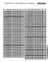
KN INSTALLATION AND OPERATION INSTRUCTIONSPage 17Figure 13 - Typical Multiple Boiler with Indirect Storage Tank PipingNOTE: Not all system valves maybe shown. Consult local codes foradditional system <strong>com</strong>ponentswhich may be necessary.CONDENSATE PIPINGThe condensate trap provided with the <strong>boiler</strong> must beattached to the bottom pan and piped to a suitable floordrain or condensate pump.GAS SUPPLY PIPINGWARNING: Check the <strong>boiler</strong> rating plate to makesure that the <strong>boiler</strong> is for the type of <strong>gas</strong> thatwill be used. If it isn’t, do not connect the <strong>boiler</strong>to the <strong>gas</strong> supply. Failure to <strong>com</strong>ply with thiswarning can result in extensive propertydamage, severe personal injury or death!The KN <strong>com</strong>es from the factory ready to be piped tothe <strong>gas</strong> supply. If for any reason the <strong>boiler</strong> is not for thetype of <strong>gas</strong> available at the <strong>installation</strong> site, call yourHydroTherm representative to resolve the problem.Table 9 should be used to ensure that the <strong>gas</strong> supplypiping is sized properly. If more than one appliance issupplied by the same supply pipe, the piping must besized based on the maximum possible demand. Do notneglect the pressure drop due to pipe fittings. Table 9should be used in conjunction with Table 10 to ensurethat the <strong>gas</strong> supply piping has the capacity to meet thedemand.Figure 14 depicts the proper way to connect the <strong>boiler</strong>to the <strong>gas</strong> supply piping. The manual shut-off valveMUST be installed in the supply piping. It should beinstalled 5 feet above the floor where required by localcodes. Provide a sediment trap at the bottom of thevertical section of the <strong>gas</strong> supply pipe upstream of the<strong>gas</strong> controls.A ground joint union should be installed between the<strong>boiler</strong> <strong>gas</strong> controls and the supply piping. Each of theseitems are needed to ensure long life and ease ofservicing. Always use a pipe sealant that is suitable foruse with LP <strong>gas</strong>.Table 9 - Gas Pipe CapacityMaximum pipe capacity in ft 3 /hr based on 0.60 specific gravity <strong>gas</strong>at a pressure of 0.5 psig or less and a 0.3" WC pressure drop.NominalIron PipeSize, (in)1″1 1 /4″1 1 /2″2″Pipe length in feet10 20 30 40 50 60 80 100 150Maximum <strong>gas</strong> volume of pipe (ft 3 /hr)520 350 285 245 215 195 170 150 1201050 730 590 500 440 400 350 305 2501600 1100 890 760 670 610 530 460 3803050 2100 1650 1450 1270 1150 990 870 710Note: Multiply the <strong>gas</strong> volume by 0.62 for propane flow capacity inft 3 /hr.Multiply the propane flow capacity by 2500 Btu/ft3 to determinethe propane Btu/hr capacity for a given pipe size and length.
Page 18KN INSTALLATION AND OPERATION INSTRUCTIONSTable 10 - Equivalent Pipe Length ChartNominalIron PipeSize, (in)1″1 1 /4″1 1 /2″Type of pipe fitting90° Elbow Tee 1 Gas Valve 2 Gas Cock 22″Notes: 1. For flow through branch.2. For flow at full open.Equivalent pipe length, (ft)2.6 5.2 0.6 1.53.5 6.9 0.8 1.94.0 8.0 0.9 2.35.2 10.3 1.2 3.0Figure 14 - Gas Supply PipingELECTRICAL WIRINGElectrical Power ConnectionsCAUTION: Label all wires prior to disconnectionwhen servicing controls. Wiring errors can causeimproper and dangerous operation! Verify properoperation after servicing.ATTENTION. Au moment de l'entretien des <strong>com</strong>mandes,étiquetez tous les fils avant de lesdébrancher. Des erreurs de câblage peuvententraîner un fonctionnement inadéquat etdangereux. S'assurer que l'appareil fonctionneadéquatement une fois l'entretirn terminé.The electrical connections to this <strong>boiler</strong> must be madein accordance with all applicable local codes and thelatest revision of the National Electrical Code, ANSI /NFPA-70. Installation should also conform with CSAC22.1 Canadian Electrical Code Part I if installed inCanada. Install a separate 120 volt 15 amp circuit forthe <strong>boiler</strong>. A properly rated shut-off switch should belocated at the <strong>boiler</strong>. The <strong>boiler</strong> must be grounded inaccordance with the authority having jurisdiction, or ifnone, the latest revision of the National Electrical Code,ANSI/NFPA-70.NOTE: An inline <strong>gas</strong> regulator must be installed upstream of the <strong>gas</strong> train and set to the lowestexpected service pressure. Choose a regulator thathas no more than 1" pressure drop.CAUTION: Always use a wrench on the <strong>gas</strong> valvebody when making <strong>gas</strong> connections to it. Neverover-tighten the piping entering the <strong>gas</strong> valve bodyor <strong>gas</strong> valve failure may result!Safe lighting and other performance criteria were metwith the <strong>gas</strong> manifold and control assembly provided onthe <strong>boiler</strong>. All <strong>gas</strong> connections MUST be leak testedbefore putting the <strong>boiler</strong> into operation.WARNING: Never use an open flame to test for<strong>gas</strong> leaks. Always use an approved leakdetection method. Failure to <strong>com</strong>ply with thiswarning can cause extensive property damage,severe personal injury or death!Whenever the <strong>gas</strong> supply piping is pressure tested the<strong>boiler</strong> <strong>gas</strong> controls must be protected. If the testpressure is equal to, or less than 1/2 psig, 3.5 kPaisolate the <strong>boiler</strong> by closing its' manual shut off valve,see Figure 14. If the test pressure is greater than, orequal to 1/2 psig, 3.5 kPa, disconnect the <strong>boiler</strong> andits individual shut-off valve.Line voltage field wiring of any controls or other devicesmust use copper conductors with a minimum size of #14awg. Use appropriate wiring materials for units installedoutdoors.Refer to the wiring diagram supplied with the <strong>boiler</strong> forproper wiring connections.BOILER OPERATIONWARNING: Before proceeding read and fullyunderstand the instructions contained in thismanual. Do not attempt to operate this <strong>boiler</strong> ifit has not been installed in accordance with theguidelines set forth in this manual. Failure to<strong>com</strong>ply with this warning can result in extensiveproperty damage, severe personal injury ordeath!Should overheating occur or the <strong>gas</strong> supply fail to shutoff, turn off the manual <strong>gas</strong> control valve to theappliance. Do Not interrupt water flow through the <strong>boiler</strong>.En cas de surchauffe ou si l'alimentation en gaz nes'arrête pas, fermez manuellement le robinet d'arrêt del'admission de gaz.
KN INSTALLATION AND OPERATION INSTRUCTIONSPage 19Hydronic Heating BoilersOpen the make-up water valve and slowly fill the <strong>boiler</strong>and all of the radiation with water. Ensure that all bleedand drain valves are closed.Adjust the make-up water pressure regulator so aminimum 12 psig, 84 kPa system pressure ismaintained at the highest point in the system piping. Ifa make-up water pump is used adjust it as stated above.Open the system bleed and drain valves, one at a time,to purge the air trapped in the heating system piping.With the <strong>boiler</strong> off, run the system pump for at least 30minutes and bleed the system piping using the bleedvalves. If strainers are used in the system piping themake-up water valve should be closed and the strainerschecked and cleaned.The system expansion tank should be checked toensure that tank air pressure equals cold static fillpressure.Start the <strong>boiler</strong> as described in the OPERATINGINSTRUCTIONS below. Run the <strong>boiler</strong> for at least anhour. The system pump(s) and all radiation units mustbe operated during this time. Ensure that the make-upwater valve is open.Shut the <strong>boiler</strong> off and open the bleed valves to purgethe air trapped in the heating system piping. Close themake-up water valve and check and clean the strainersand make-up water pressure reducing valve.Open the make-up water valve and adjust the systempressure if necessary.The system should be checked and bled after three daysof operation.OPERATING INSTRUCTIONSFOR YOUR SAFETY READ BEFORE OPERATINGPOUR VOTRE SÉCURITÉ LISEZ AVANT DE METTREEN MARCHEA. This appliance is equipped with an ignition devicewhich automatically lights the pilot. Do not try to lightthe pilot by hand.Cet appareil est muni d'un dispositif d'allumage quiallume automatiquement la veilleuse. Ne tentez pasd'allumer la veilleuse manuellement.B. BEFORE OPERATING smell all around theappliance area for <strong>gas</strong>. Be sure to smell next to thefloor because some <strong>gas</strong> is heavier than air and willsettle on the floor.WHAT TO DO IF YOU SMELL GAS• Do not try to light any appliance.• Do not tough any electric switch; do not use anyphone in your building.• Immediately call your <strong>gas</strong> supplier from a neighbor’sphone. Follow the <strong>gas</strong> suppliers instructions.• If you cannot reach your <strong>gas</strong> supplier, call the firedepartment.AVANT DE FAIRE FONCTIONNER, reniflez tout autourde l'appareil pour déceler une odeur de gaz. Reniflezprès du plancher, car certains gaz sont plus lourds quel'air et peuvent s'accumuler au niveau du sol.QUE FAIRE SI VOUS SENTEZ UNE ODEUR DE GAZ:• Ne pas tenter d'allumer d'appareil.• Ne touchez à aucun interrupteur; ne pas vous servirdes téléphones se trouvant dans le bâtiment.• Appelez immédiatement votre fournisseur de gazdepuis un voisin. Suives les instructions dufournisseur.• Si vous ne pouvez rejoindre le fournisseur, appelezle service de incendies.C. Do not use this appliance if any part has been underwater. Immediately call a qualified service technicianto inspect the appliance and to replace any part ofthe control system and any <strong>gas</strong> control that hasbeen under water.N'utilisez pas cet appareil s'il a été plongé dans l'eau,même partiellement. Faites inspecter l'appareil par untecnicien qualifié et remplacez toute partie du systèmede contrôle et toute <strong>com</strong>mande qui ont été plongés dansl'eau.Operating Instructions1. STOP! Read the safety information above. If, at anytime, the appliance will not operate properly, followthe instructions “TO TURN OFF GAS TOAPPLIANCE” and call your service technician or <strong>gas</strong>supplier.2. Set the <strong>operating</strong> control to off or its lowest setting.3. Turn off all electric power to the appliance.4. Remove the front plastic cover.5. Close manual main shut-off valves 1 and 2 and thepilot <strong>gas</strong> shut-off valve, Figure 14.
Page 20KN INSTALLATION AND OPERATION INSTRUCTIONS6. Purge the <strong>gas</strong> piping up to the manual valve aheadof the main <strong>gas</strong> control of air. When the bleeding is<strong>com</strong>plete, check all <strong>gas</strong> joints up to the <strong>gas</strong> valvefor leaks.7. Install a fitting at the bleed point and connecta manometer having a minimum range of 20 in,508 mm WC to it, Figure 14.8. Remove the 1/8" pipe plug from the pilot tee andconnect a manometer having a minimum range of6 in, 154 mm WC to it.9. Wait five (5) minutes to clear out any <strong>gas</strong>.10. Open the manual main shut-off valves 1 and 2 andthe pilot <strong>gas</strong> shut-off valve, Figure 14.11. Turn the power switch on the front of the <strong>boiler</strong> to“on”. It will light up when the power is on. If allinterlocks are properly closed, the display will say“Standby KN-10”, Figure 15.12. Move the slide switch below the display to “Min.hold”, Figure 15.13. Create a full input demand be jumping the AAterminals, or applying 20 ma to the current inputterminals, Figure 15.14. The <strong>boiler</strong> will begin the start sequence.Figure 15 - Control Panel15. When the main display reads “PIOLT RUNNING”and the flame current is 5VDC, switch the Honeywell7800 to the “test” position, Figure 15. This willhold the Honeywell 7800 in its ignition state.16. Adjust the pilot pressure per the CHECKING,ADJUSTMENT & OPERATION section below.17. Remove the demand from the 7800 control, allowingthe <strong>boiler</strong> to stop.18. Remove the manometer fitting from the pilot tee andreplace the plug. Close manual main shut-off valve2 and the pilot <strong>gas</strong> shut-off valve, Figure 14.19. Switch the Honeywell 7800 back to “run”.20. Create a full input demand as before. The <strong>boiler</strong> willbegin the start sequence.21. Monitor the flame current on the 7800. No flamecurrent should be detected and the 7800 shouldlock out. If flame current is detected at any time upto the 7800 locking out, the 120V wiring on theignition transformer must be reversed and the testrun again to insure that no flame is detected.WARNING: Improper wiring of the ignitiontransformer can result in an explosion causingextensive property damage, severe personalinjury or death!22. Open both manual main shut-off valves and the pilot<strong>gas</strong> shut-off valve.23. Reset the Honeywell 7800. The <strong>boiler</strong> will start andwill run at minimum input rate.24. Observe the burner to ensure that it is not <strong>operating</strong>in an infrared condition during low fire operation.Take a flue <strong>gas</strong> sample using a calibrated analyzer.Use a 2.5mm, 3/32" allen wrench to adjust the <strong>gas</strong>valve to produce a CO2 the same as high fire 8-9%natural <strong>gas</strong> and 9-10% L.P., Figure 14. Make small10 degree adjustments and wait until the CO2readings settle before making further adjustments.25. Rotate the screw clockwise to increase the rate,counter clockwise to decrease it.26. Move the slide switch to the “auto” position. The<strong>boiler</strong> input will rise to its maximum input.27. Allow the <strong>boiler</strong> to stabilize and adjust the input rateper the CHECKING, ADJUSTMENT & OPERATIONsection below.
KN INSTALLATION AND OPERATION INSTRUCTIONSPage 21Instructions De Mise En Marche1. ARRÊTEZ! Lisez les instructions de sécurité sur laportion supérieure de cette étiquette.2. Réglez le thermostat à la température la plus basse.3. Coupez l'alimentation électrique de l'appareil.4. Cet appareil est muni d'un dispositif d'allumage quiallume automatiquement la veilleuse. Ne tentez pasd'allumer la veilleuse manuellement.5. Fermer la vanne manuelle d'arrêt d'alimintation degaz.6. Attendre cinq (5) minutes pour laisser échapper toutle gaz. Reniflez tout autour de l'appareil, y <strong>com</strong>prisprès du plancher, pour déceler une odeur de gaz.Si vous sentez une odeur de gaz, ARRÊTEZ!Passez à l'étape B des instructions de sécurité surla portion supérieure de cette étiquette. S'il n'y a pasd'odeur de gaz, passez à l'étape suivante.7. Ouver la vanne manuelle d'arrêt d'alimintation degaz.8. Mettez l'appareil sous tension.9. Réglez le thermostat à la température désirée.10. Si l'appareil ne se met pas en marche, suivez lesinstructions intitulées couper l'admission de gaz del'appareil et appelez un technicien qualifié ou lefournisseur de gaz.TO TURN OFF GAS TO APPLIANCE1. Set the <strong>operating</strong> control to its lowest setting.2. Turn off all electric power to the <strong>boiler</strong> if service isto be performed.3. Close the manual main and pilot <strong>gas</strong> shut-off valves.COMMENT COUPER L'ADMISSION DE GAZ DEL'APAREIL1. Réglez le thermostat à la température la plus basse.SEQUENCE OF OPERATIONNO DEMANDStandby1. The <strong>boiler</strong> is idle with no interlocks in the faultcondition.DEMANDPre-Purge1. The blower operates at purge RPM. The water flowinterlock must ‘make’ within 15 seconds after thedemand signal is initiated.2. The Honeywell 7800 starts a 10 second purge delayonce the air prove switch contacts close.Pilot Run - %Input1. The blower operates at minimum % input RPM.2. The ignition transformer is energized. The pilotsolenoid valve opens for the 10 second pilot ignitiontrial.Main Run %Input1. The main <strong>gas</strong> valve opens.2. The ignition transformer is de-energized.3. The pilot solenoid valve closes.4. The blower stays at the minimum input RPM for3 seconds then operates at demand % inputNO DEMANDPost-Purge1. The main <strong>gas</strong> valve closes.2. The blower operates at purge RPM for 10 seconds.3. The <strong>boiler</strong> is idle with no interlocks in the faultcondition.2. Coupez l'alimentation électrique de l'appareil s'il fautprocéder à l'entretien.3. Fermer la vanne manuelle d'arrêt d'alimintation degaz.
Page 22KN INSTALLATION AND OPERATION INSTRUCTIONSCHECKING, ADJUSTMENT & OPERATIONFigure 17 - Pilot FlameSpark GapThe gap has to be measured and adjusted with theigniter removed from the <strong>boiler</strong>. Observe the trial forignition to confirm that the spark is strong andcontinuous. If not check and adjust the spark gap asshown in Figure 16.Figure 16 - Spark GapPilot AdjsutmentThe pilot pressure has been factory set at 1.5" andshouldn't need adjustment. To check the pilot pressureclose the manual main shut-off valve 2 and the pilot <strong>gas</strong>shut-off valve, Figure 14. Remove the 1/8" pipe plugfrom the pilot tee and connect a manometer having aminimum range of 6 in, 154 mm WC to it. the Open thepilot <strong>gas</strong> shut-off valve. With the unit powered generatea call for heat. When the prepurge is <strong>com</strong>plete theignition/pilot trial will begin. At this point put theHoneywell 7895C test switch in the test position. Thecontrol will hold in the ignition/pilot sequence allowingyou to check the pressure.To adjust the pilot the following steps must betaken:1. Remove the pilot <strong>gas</strong> pressure regulator cap.2. Turn the pressure regulator adjustment screw clockwiseto increase the pressure and counterclockwiseto decrease it.3. Replace the pressure regulator adjustment screwcap.CAUTION: Never force the regulator adjustmentscrew beyond the stop limits or damage to theregulator will occur!Pilot flame UV signalBefore you check the pilot signal you need to make surethe polarity of the 120v supply to the ignition transformeris correct. To do this close the manual main shut-offvalve 2 (Figure 14) and the manual pilot shut-off valve.With the unit powered generate a call for heat. The <strong>boiler</strong>will start to go through it start up sequence. During theignition/pilot sequence observe the lights on theHoneywell 7895C. The pilot light should <strong>com</strong>e on but notthe flame light. If the flame light <strong>com</strong>es on along withthe pilot light, interrupt the call for heat and turn off themain power. Reverse the 120v supply leads to theHoneywell 652B ignition transformer and run this testagain. With this done the flame signal should bebetween 3vdc and 5vdc. Check the voltage on the testconnections of the Honeywell 7895C's amplifier with adc voltmeter.Main Burner CombustionThe fuel/mixture on full fire is not adjustable. TheCO 2 was checked at the factory and should beapproximately 8.5% to 8.8%. However if the CO 2 is wellout of this range something is wrong. Check if the endof the <strong>gas</strong> pipe is centered in the 2" x 5" air orifice inthe filter box. The end of the pipe should be centeredin and square to the opening, and it should be insertedby approximately 3/8". Also make sure the entire <strong>gas</strong>train is secured tightly to its support arms.The fuel/air mixture on min or low fire is adjustable. Thismixture was set at the factory to match that of the fullfire. Therefore the CO 2 should be approximately thesame over the entire firing range.
KN INSTALLATION AND OPERATION INSTRUCTIONSPage 23To confirm the input of the unit follow the instructions inthe INPUT RATE section below.1. A flue <strong>gas</strong> sample must be taken at the flue outletusing a calibrated flue <strong>gas</strong> analyzer. Allow the unitto run for 15 minutes before taking the sample.For a natural <strong>gas</strong> unit the CO 2 reading should be8.5% - 8.8%. An LP unit will have CO 2 readingsproportionally higher.2. To test the ignition safety shutoff device, close themanual shutoff valve 1 (Figure 14) in the <strong>gas</strong> supplyline. Within 5 seconds of main burner flameextinction, the main <strong>gas</strong> valve solenoid should close.The control board will lockout and display “LOWGAS PRESSURE”. Open the manual shutoff valvein the <strong>gas</strong> supply line and reset the control boardby toggling the power switch.Input Rate, Natural Gas1. Turn off all other <strong>gas</strong> appliances that use the same<strong>gas</strong> meter as the <strong>boiler</strong>.2. Call your <strong>gas</strong> supplier and ask for the heating valueof the <strong>gas</strong> (Btu per cu/ft).3. Start the <strong>boiler</strong> and let it run for 15 minutes.4. With the <strong>boiler</strong> operation clock the time that it takesto burn 10 cu/ft of <strong>gas</strong> at full fire.5. Insert the heating value and the time, in seconds,into the formula below.6. Input = 10 / seconds (Btu per cu/ft)(3600).7. If the <strong>com</strong>puted rate exceeds the desired input rateor 1,000,000 Btu/hr reduce the input. To do this usethe maximum Btu adjustment pot located on theface of the display, Figure 15.CAUTION: Never increase the input to the <strong>boiler</strong>above that for which it is rated. Doing so can causepremature failure of the <strong>boiler</strong>!Low Water CutoffEnsure that the low water cutoff device(s) functionproperly.Test in accordance with the manufacturer’s instructionsincluded with the device(s).DIAGNOSTICSThe KN has a display that indicates the sequence ofoperation, Figure 15. The display will also list faultsshould the unit fail to operate. An explanation of eachfault is listed below.STANDBY KN-10: Indicates that power is beingsupplied to the unit and there is no call for heat.STANDBY OPERATING LIMIT: Indicates that the<strong>operating</strong> limit if used is open.HONEYWELL ALARM “flashing”: Indicates that thereis a call for heat and the Honeywell 7895C is locked out.STANDBY START DEMAND: Indicates that there is acall for heat and the Honeywell 7895C is not functioningor is locked out.STANDBY WATER LIMIT: Indicates that either the highlimit, low water cut off, or both are open without a callfor heat.LOCKOUT WATER LIMIT: Indicates that either the highlimit, low water cut off, or both are open with a call forheat.STANDBY GAS PRESSURE: Indicates that the low <strong>gas</strong>pressure switch or the high <strong>gas</strong> pressure switch if usedis open without a call for heat.LOCKOUT GAS PRESSURE: Indicates that the low<strong>gas</strong> pressure switch or the high <strong>gas</strong> pressure switch ifused is open with a call for heat.STANDBY FLOW SWITCH: Indicates that the waterflow switch is open without a call for heat.OPTIONAL LOCKOUT FLOW SWITCH: Indicates thatthe water flow switch is open with a call for heat.UV SCANNER SWITCH “flashing”: Indicates that theUV scanner air pump proving switch is open with the<strong>boiler</strong> running.STANDBY TEKTRA ALARM: Indicates a problem withthe Tekmar <strong>operating</strong> control without a call for heat.LOCKOUT TEKTRA ALARM: Indicates a problem withthe Tekmar <strong>operating</strong> control with a call for heat.LWCO LOCKOUT: Indicates low or no water in the<strong>boiler</strong>.
Page 24KN INSTALLATION AND OPERATION INSTRUCTIONSMAINTENANCEWARNING: Disconnect electrical power andclose the manual <strong>gas</strong> shut off valve beforeperforming maintenance or severe personalinjury may result!CAUTION: Servicing, inspection and adjustmentmust be done by a trained technician in accordancewith all applicable local and national codes.Improper servicing or adjustment can damage the<strong>boiler</strong>!The <strong>boiler</strong> must be cleaned and inspected at least oncea year and before each heating season. Make sure thatthe burner and ignition <strong>com</strong>ponents are free from dust,soot, dirt, corrosion or other deposits that would impairthe <strong>boiler</strong>’s performance. Refer to page 26 for<strong>com</strong>ponent identification.CAUTION: Improper burner servicing can result inpremature burner failure voiding the warranty!Burner Removal & InspectionWARNING: The ceramic <strong>com</strong>bustion chamber inthe burner box and its <strong>gas</strong>ket contain crystallinesilica. Wear a tightly fitted dust mask whenservicing the burner and gently handle theburner and its <strong>gas</strong>ket to prevent inhalation ofairborne fibers. Crystalline silica fibers havebeen identified as carcinogenic, or possiblycarcinogenic when inhaled.NOTE: Do not attempt to remove the burner withouthaving a burner <strong>gas</strong>ket kit on hand.1. Close the manual shutoff valves in the <strong>gas</strong> supplyline and turn off electrical power to the <strong>boiler</strong>.2. Disconnect the pilot line. Disconnect the blower/filter box assembly from the blower adapter.3. Loosen the two screws on the filter box supportbracket below the filter box.4. Remove the top casting.5. Remove the burner retaining nuts and springs.6. Remove the flow director.7. Carefully lift the burner out of the unit.8. Inspect the burner for damage or dirt buildup.9. If the burner is dirty use a vacuum to clean it. If theburner has be<strong>com</strong>e extremely dirty it may need tobe replaced.10. DO NOT reinstall a damaged burner. Replace it.11. Replace all old <strong>gas</strong>kets with new ones from theburner <strong>gas</strong>ket kit.12. Reassemble the unit following the removal steps inreverse order.Heat Exchanger CleaningIn the unlikely event that the heat exchanger be<strong>com</strong>esblocked consult the factory for the proper cleaningprocedure.Air Intake & Vent SystemThoroughly inspect the air intake and vent systemsfor any signs of blockage, corrosion or leakage.Immediately replace any unsound vent system piping.Inspect the air filter and wash with warm water and soapif dirty.ControlsUse the BOILER OPERATION and CHECKING ANDADJUSTMENT sections of this manual for reference.1. Check the <strong>operating</strong> controls for proper operation.2. A float type low water cutoff device must be flushedout per the manufacturers' instructions. The probeon a probe low water cut off must be removed,cleaned and inspected at least once a year. Ensurethat the low water cutoffs operate properly. In not,replace them.3. The flow switch contacts must be open when waterflow is not present.4. The relief valve should not weep or discharge waterat normal system pressure. If it does contact aqualified service technician to have it inspected.NEVER try to clean or repair the relief valve! If thevalve fails to operate properly, have it replaced!5. The aquastat high limit controls the maximum watertemperature in the <strong>boiler</strong>. It is adjustable from 130°F,54°C to 215°F, 102°C. If the water temperaturereaches the set temperature before the demand forheat has been met, the aquastat high limit shouldshut the <strong>boiler</strong> off. The water temperature shouldnever exceed the maximum set point of 215°F,102°C.The aquastat high limit cannot be repaired.If it fails to function properly replace it.
KN INSTALLATION AND OPERATION INSTRUCTIONSPage 256. Visually check the pilot and main burner flames toensure proper operation, see Figures 17 & 18.Figure 18 - Main Burner FlameWARNING: If the surface of the burner glowsbright orange it indicates infrared operation. Ayellow, floating flame indicate a lack of<strong>com</strong>bustion air. If either occur do not operatethe <strong>boiler</strong> until the problem is solved or severepersonal injury or death may occur!TROUBLESHOOTINGOPERATIONAL PROBLEMThe "Power On" light doesn't illuminate.Lockout water limit is displayed with a call for heat.Lockout <strong>gas</strong> pressure is displayed with a call for heat.Lockout flow switch is displayed with a call for heat.UV scanner switch is displayed flashing along withthe normal running display.Lockout Tektra alarm is displayed with a call for heatCORRECTIVE ACTIONEnsure that proper voltage is being supplied to the unitInspect the circuit breaker for the <strong>boiler</strong> circuitCheck the lightEnsure that the power switch operates properly and iswired correctlyCheck both the high limit and low water cut off.Ensure that the <strong>boiler</strong> has been <strong>com</strong>pletely purgedof air.Ensure that all system valves are in the correctposition.Ensure that the manual main <strong>gas</strong> valve is open.Ensure that there is sufficient <strong>gas</strong> pressure supplyingthe <strong>boiler</strong>.Check pressure setting on the low <strong>gas</strong> pressureswitch.Ensure that there is sufficient water flow through the<strong>boiler</strong>Ensure the scanner-cooling pump is <strong>operating</strong>.Make sure there are no obstructions in the tubingsupplying the air to the scanner.There is a problem with the Tekmar <strong>operating</strong> control.Refer to the Tekmar literature.
Page 26KN INSTALLATION AND OPERATION INSTRUCTIONSFigure 19 - Exploded ViewHIOM-19
KN INSTALLATION AND OPERATION INSTRUCTIONSPage 27SERVICE AND REPLACEMENT PARTS LISTModel Size with Item Quantities BelowItem Description Part # KN-6 KN-10 KN-201 FILTER BOX WELDMENT 70-1346 1FILTER BOX WELDMENT 70-1280 12 BLOWER TO AIR FILTER GASKET 59-1067 1 13 FILTER 59-1057 1FILTER 59-1069 14 FILTER BOX FRONT COVER 03-1622 15 FILTER BOX SUPPORT BRACKET 03-1651 1FILTER BOX SUPPORT BRACKET 03-1700 16 POTENTIOMETER ADJ. LABEL 42-5213 1 17 BOILER TEMPERATURE CONTROL 02-4250 1 18 PRESS. SW, MPL 9300-25 02-4881 1 19 ELECTRONICS PANEL 60-5602 1 110 CONTROL PCBOARD 02-4249 1 111 ILLUMINATED ROCKER SWITCH 58-1536 1 112 CONTROL PANEL OVERLAY 60-5601 1CONTROL PANEL OVERLAY 60-5612 113 SCANNER COOLING PUMP 09-1518 1 114 BURNER CONTROLLER 02-4012 1 115 30 VA QUICK CONNECT TRANSFOMER 26-3208 1 116 FRONT COMPONENT COVER 60-5600 1 117 ELECTRONICS MOUNT PAD ASSY 70-1330 1 118 STRUT PIPE CLAMP 56-5909 3STRUT PIPE CLAMP 56-5911 319 GAS TRAIN LOWER BRACKET 70-1333 2GAS TRAIN LOWER BRACKET 70-1276 220 GAS VALVE ORIFICE GASKET 59-1068 1 121 MAIN GAS ORIFICE 03-1647 1MAIN GAS ORIFICE 03-1691 122 FREQENCY DRIVE 58-1846 1 123 Strut Pipe Clamp 56-5910 1 124 CONDENSATE DRAIN ASSY 70-1338 1 125 DRAIN MOUNTING BRACKET 03-1650 1 126 GAS VALVE 02-1570 1GAS VALVE 02-1574 127 PLASTIC COVER LOWER MOUNTING BRACKET 03-1645 1 128 RUBBER GROMMET .750 in ID, 1.625 in OD 57-5427 3 329 FRONT JACKET PANEL 03-1603 1FRONT JACKET PANEL 03-1687 130 DRAW ROD NUT, 5/8-11 UNC 57-2616 12 1231 FRONT CASTING SECTION 01-1629 1 132 DRAW ROD 5/8"-11 44-1125 6DRAW ROD 44-1127 633 BASE, BOTTOM TUBING 06-1000 2BASE, BOTTOM TUBING 06-1103 234 INTERMEDIATE CASTING SECTION 01-1628 4INTERMEDIATE CASTING SECTION 01-1628 235 FLUE BAFFLE 59-1062 536 BOTTOM CASTING COVER 01-1631 1BOTTOM CASTING COVER 01-1635 137 PLASTIC COVER UPPER MOUNTING BRACKET 03-1646 1 138 1" CONDUIT END 58-1605 2 239 3" SQUARE SOCKET PLUG 56-4586 1 340 LEFT SIDE LOWER JACKET PANEL 03-1606 1LEFT SIDE LOWER JACKET PANEL 03-1702 141 1" CONDUIT WIREWAY 20' 40-1010 11" CONDUIT WIREWAY 20' 70-1264 1
Page 28KN INSTALLATION AND OPERATION INSTRUCTIONSModel Size with Item Quantities BelowItem Description Part # KN-6 KN-10 KN-2042 PORT SEAL 59-1066 8 1043 PRESSURE/TEMP. GAUGE 20-1020 1 144 LEFT SIDE UPPER JACKET PANEL 03-1605 1LEFT SIDE UPPER JACKET PANEL 03-1701 145 REAR CASTING SECTION 01-1627 1 146 UV PIPE NIPPLE 53-1028 1 147 REAR EXTERNAL WIRE COVER 03-1623 1 148 REAR JACKET PANEL 03-1604 1REAR JACKET PANEL 03-1688 149 SCANNER COOLING PUMP PROVE SW. BRACKET 03-1652 1 150 SCANNER COOLING PUMP PROVE SWITCH 02-5208 1 151 IGNITION TRANSFORMER 26-3207 1 152 BOILER EXT. NIPPLE 70-1347 1 153 FLOW SWITCH (OPTIONAL) 21-2101 1 154 REAR IGNITOR COVER ASSY 70-1336 1 155 VIEW PORT GLASS GASKET 59-1063 2 256 IGNITOR ASSY 70-1345 1 157 CERAMIC FIBER CHAMBER 45-1266 1CERAMIC FIBER CHAMBER 45-1269 158 CERAMIC FIBER CHAMBER LOWER GASKET 59-1065 1CERAMIC FIBER CHAMBER LOWER GASKET 59-1080 159 BURNER MOUNTING PLATE GASKET 59-1064 1BURNER MOUNTING PLATE GASKET 59-1081 160 BURNER MOUNTING PLATE 03-1602 1BURNER MOUNTING PLATE 03-1694 161 HIGH LIMIT AQUASTAT W/MAN. RESET 02-2802 1 162 BURNER GASKET 59-1060 3BURNER GASKET 59-1082 363 BURNER HOLD DOWN ASSY 70-1335 1BURNER HOLD DOWN ASSY 70-1286 164 BURNER SPRING 60-4292 2 265 BURNER SPRING RETAINER 60-4254 2 266 PILOT ELBOW 60-4252 1 167 PILOT ORIFICE NAT. GAS 25-0061 1 168 PILOT TUBE 54-2119 1PILOT TUBE 70-1265 169 PILOT GUIDE 60-4250 1 170 INTAKE PLENIUM 01-1630 1INTAKE PLENIUM 01-1634 171 BLOWER FLANGE REAR GASKET 59-1059 1 172 INTAKE SPOOL ASSY 70-1337 1 173 BLOWER FLANGE FRONT GASKET 59-1058 1 174 BURNER PLAQUE 45-1265 1BURNER PLAQUE 45-1268 175 VIEW PORT GLASS 60-4280 1 176 VIEW PORT GLASS BRACKET 60-4281 1 177 BLOWER ASSY. 58-1848 1 178 GAS TRAIN UPPER BRACKET 70-1332 1GAS TRAIN UPPER BRACKET 70-1287 179 FLUE ADAPTER GASKET 59-2069 1FLUE ADAPTER GASKET 01-5038 1WIRE HARNESS ELECTRICAL KN-101 WIRE HARNESS DUNGS GAS VALVE 70-2024 1 12 WIRE HARNESS FASCO BLOWER 70-2025 1 13 WIRE HARNESS HONEYWELL 70-2026 1 14 WIRE HARNESS ON OFF SWITCH 70-2027 1 15 WIRE HARNESS TEKTRA (TEKMAR) 70-2029 1 16 WIRE HARNESS TRANSFORMER 70-2030 1 1
KN INSTALLATION AND OPERATION INSTRUCTIONSPage 29
Page 30KN INSTALLATION AND OPERATION INSTRUCTIONS
KN INSTALLATION AND OPERATION INSTRUCTIONSPage 31
Page 32KN INSTALLATION AND OPERATION INSTRUCTIONS